JP5253148B2 - Delivery of molecules to the lipid bilayer - Google Patents
Delivery of molecules to the lipid bilayer Download PDFInfo
- Publication number
- JP5253148B2 JP5253148B2 JP2008502471A JP2008502471A JP5253148B2 JP 5253148 B2 JP5253148 B2 JP 5253148B2 JP 2008502471 A JP2008502471 A JP 2008502471A JP 2008502471 A JP2008502471 A JP 2008502471A JP 5253148 B2 JP5253148 B2 JP 5253148B2
- Authority
- JP
- Japan
- Prior art keywords
- probe
- lipid bilayer
- membrane protein
- carrier surface
- planar lipid
- Prior art date
- Legal status (The legal status is an assumption and is not a legal conclusion. Google has not performed a legal analysis and makes no representation as to the accuracy of the status listed.)
- Expired - Fee Related
Links
Images


Classifications
-
- G—PHYSICS
- G01—MEASURING; TESTING
- G01N—INVESTIGATING OR ANALYSING MATERIALS BY DETERMINING THEIR CHEMICAL OR PHYSICAL PROPERTIES
- G01N33/00—Investigating or analysing materials by specific methods not covered by groups G01N1/00 - G01N31/00
- G01N33/48—Biological material, e.g. blood, urine; Haemocytometers
- G01N33/50—Chemical analysis of biological material, e.g. blood, urine; Testing involving biospecific ligand binding methods; Immunological testing
-
- C—CHEMISTRY; METALLURGY
- C12—BIOCHEMISTRY; BEER; SPIRITS; WINE; VINEGAR; MICROBIOLOGY; ENZYMOLOGY; MUTATION OR GENETIC ENGINEERING
- C12M—APPARATUS FOR ENZYMOLOGY OR MICROBIOLOGY; APPARATUS FOR CULTURING MICROORGANISMS FOR PRODUCING BIOMASS, FOR GROWING CELLS OR FOR OBTAINING FERMENTATION OR METABOLIC PRODUCTS, i.e. BIOREACTORS OR FERMENTERS
- C12M35/00—Means for application of stress for stimulating the growth of microorganisms or the generation of fermentation or metabolic products; Means for electroporation or cell fusion
Abstract
Description
本発明は、平面脂質二重層内への挿入のための、膜タンパク質の平面脂質二重層への送達に関する。 The present invention, for insertion into the planar lipid bilayer, to delivery to the planar lipid bilayer membrane proteins.
中に膜タンパク質が挿入された脂質二重層は、特に細胞膜として、生体系のいくつかのタイプにおける膜を構成する。そのような生体膜にインスパイアされ、平面脂質二重層に挿入された膜タンパク質に関連した多数の技術が開発されている。これらの技術においては、膜タンパク質または別の分子を平面脂質二重層へ送達することが必要である。 Lipid bilayers with membrane proteins inserted in them constitute membranes in several types of biological systems, especially as cell membranes. A number of techniques have been developed that relate to membrane proteins that are inspired by such biological membranes and inserted into planar lipid bilayers. In these techniques, it is necessary to deliver a membrane protein or another molecule to the planar lipid bilayer.
そのような技術の1つが確率的センシング(stochastic sensing)であって、その中において、分子または肉体の刺激への膜タンパク質の反応が、その分子または刺激のセンシングの実施に使用される。そうした反応の性質は、膜タンパク質の性質に依存するが、膜タンパク質は、天然のタンパク質であっても、あるいは、多くの有用な適用において人工的に作り出したタンパク質であってもよい。センシングの1つのタイプにおいて、膜タンパク質は、タンパク質ポアまたはタンパク質チャネルであって、それは、脂質二重層全体に電気信号を作用させること、例えば、脂質二重層に流れるイオン電流を変えることによって、検体に反応する。この場合、検体のセンシングは、脂質二重層全体において電気信号を検出することによって行ってもよい。確率的センシングは、例えば、イオン、有機分子、またはペプチドなどのセンシング、DNAの特徴づけ、リガンドとレセプターの相互作用の検査、および多段階の反応経路の検査などの広範囲の生体分子および生体系のセンシングを可能にする。 One such technique is stochastic sensing, in which the response of a membrane protein to a molecule or physical stimulus is used to perform the sensing of that molecule or stimulus. The nature of such a reaction depends on the nature of the membrane protein, but the membrane protein may be a natural protein or an artificially created protein in many useful applications. In one type of sensing, a membrane protein is a protein pore or protein channel that acts on an analyte by applying an electrical signal across the lipid bilayer, for example, by changing the ionic current that flows through the lipid bilayer. react. In this case, the specimen may be sensed by detecting an electrical signal in the entire lipid bilayer. Stochastic sensing can be used for a wide range of biomolecules and systems such as sensing ions, organic molecules, or peptides, characterizing DNA, examining ligand-receptor interactions, and examining multi-step reaction pathways. Enable sensing.
確率的センシングなどの技術の多用途性にもかかわらず、実用的な方法は面倒で費用がかかり、熟練の科学者によって行われる必要がある。大きな困難は、センシング実施のために平面脂質二重層内に膜タンパク質を挿入するために使用される技術にある。最も一般的な技術は、精製された形態の膜タンパク質を溶液に懸濁し、続いて膜タンパク質が平面脂質二重層に拡散し、平面脂質二重層に結合することによって挿入され、機能状態に組み入れられる間、待つというものである。しかし、実施において、単一の膜タンパク質を脂質二重層内に挿入するのは、非常に速度が遅く、信頼できない場合があり得る。確率的センシングの場合、単一のポアを有するのが好ましい。なぜならば、複数のポアの場合、動態解析を妨げるか、あるいは少なくとも複雑にするからである。複数のポアにおける挿入を防ぐために、膜タンパク質の濃度が低い溶液が使用される。膜タンパク質が平面脂質二重層内に挿入されるのにかかる時間は、一般的には数十分である。速度が遅いことと科学者にとってストレスのたまるものであることを別にしても、こうしたことは、上述の技術をどのように商業的に適用するに当たっても不利益である。 Despite the versatility of technologies such as stochastic sensing, practical methods are cumbersome and expensive and need to be performed by skilled scientists. A major difficulty lies in the technology used to insert membrane proteins into the planar lipid bilayer for sensing. The most common technique is to suspend a membrane protein purified form in solution, followed by membrane proteins is diffused in the planar lipid bilayer, it is inserted by binding to planar lipid bilayers, incorporated functional state Wait for a while. However, in practice, the insertion of a single membrane protein into a lipid bilayer can be very slow and unreliable. For stochastic sensing, it is preferable to have a single pore. This is because, in the case of multiple pores, dynamic analysis is hindered or at least complicated. A solution with a low concentration of membrane protein is used to prevent insertion in multiple pores. The time taken for a membrane protein to be inserted into a planar lipid bilayer is generally tens of minutes. Apart from being slow and stressful for scientists, this is detrimental to how the above-described technology is applied commercially.
関連した問題が、新しく人工的に作り出したタンパク質においても起こる。この場合において、活性の不足がある場合、人工的に作り出した膜タンパク質が平面脂質二重層内に挿入されるための機能が働かないためであるのか、それとも、不十分な濃度、異なる吸着特性、または単に十分に時間が経過していないなどの別の要因によるものであるのかが、不明である。 A related problem also occurs in newly engineered proteins. In this case, if there is a lack of activity, it may be because the function of the artificially created membrane protein to be inserted into the planar lipid bilayer does not work, or an insufficient concentration, different adsorption characteristics, Or it is unclear whether it is due to another factor such as simply not enough time.
更に、単一のポアが一旦挿入されてモニタリングが開始されても、続いて別の膜タンパク質が溶液から平面脂質二重層へと挿入されてしまうことによって、実験が台無しになり得る。この問題の一つの可能な解決法は、単一のポアが挿入された後に装置をかん流させて、溶液から余分なタンパク質を除去することである。しかし、これは難儀で信頼できない工程であり、しばしば平面脂質二重層が破裂する結果となる。 Furthermore, once a single pore is inserted and monitoring begins, the experiment can be spoiled by subsequent insertion of another membrane protein from the solution into the planar lipid bilayer. One possible solution to this problem is to perfuse the device after a single pore has been inserted to remove excess protein from the solution. However, this is a difficult and unreliable process, often resulting in the rupture of the planar lipid bilayer.
実施上の問題として、膜タンパク質の挿入に要する時間を最小限にとどめるためには、比較的広い面積の平面脂質二重層を使用する必要がある。しかし、電気的雑音を低くし、安定性を高めるためには、平面脂質二重層の面積を減らすことが望ましいであろう。 As a practical matter, it is necessary to use a relatively large area planar lipid bilayer in order to minimize the time required for the insertion of membrane proteins. However, it may be desirable to reduce the area of the planar lipid bilayer in order to reduce electrical noise and increase stability.
上記のような実践上の問題点はまた、いくつかの適用において望まれているであろう、アレイフォーマットにおける膜タンパク質の適用の可能性を狭めてしまう。 The practical issues as described above also narrow the potential application of membrane proteins in array formats, which may be desired in some applications.
これらの問題のうちの少なくともいくつかを軽減する技術の開発が望まれるであろう。 It would be desirable to develop techniques that alleviate at least some of these problems.
本発明によれば、[請求項1]が提供される。 According to the present invention, [Claim 1] is provided.
膜タンパク質を平面脂質二重層に送達するこの方法は、単に膜タンパク質を溶液に入れて待つという上記の既知の技術を超える多数の利点を生み出す。主要な利点は、この方法が迅速で容易に実施できることである。膜タンパク質をプローブ上に置き、プローブを移動させて、平面脂質二重層に対して固定する工程は、実験的に実施が非常に単純で、多大なスキルや専門知識を必要としない。プローブは巨視的な要素であり、手動で、またはマイクロマニピュレータなどの機械システムによって操作されることが可能である。これらの工程はまた、非常に迅速に実施され得る。 This method of delivering the membrane protein to the planar lipid bilayer creates a number of advantages over the known techniques described above, simply waiting for the membrane protein in solution. The main advantage is that this method is quick and easy to implement. The process of placing the membrane protein on the probe, moving the probe, and immobilizing it against the planar lipid bilayer is very simple to perform experimentally and does not require great skill and expertise. A probe is a macroscopic element that can be operated manually or by a mechanical system such as a micromanipulator. These steps can also be performed very quickly.
プローブを移動させて、平面脂質二重層に対してキャリア表面を固定する工程によって、膜タンパク質が平面脂質二重層に挿入される。実際には、平面脂質二重層に対してキャリア表面を固定させた後、挿入は非常に迅速に起こる。一般的に、挿入は固定から2、3秒以内に起こる。このスピードは実際面において非常に重要である。なぜならば、膜タンパク質を溶液に加えて二重層内に挿入されるのを待つことによって得られ得るよりも何倍も高い率で、実験の実施を反復できるからである。この既知の技術に比べ、本発明は、非常にハイスループットな実験の可能性を提供する。更に、ユーザ側のスキルのレベルがずっと低くとも、スピードが得られ得る。例えば、前記方法は、異なる膜タンパク質および/または検体のハイスループットなスクリーニングを提供するために適用されてもよい。本発明の高速さが特に有用であろう例としては、とりわけ以下のものが含まれる:(1)チャネル、ポア、またはその他の膜タンパク質の機能研究;および(2)検体の存在下での膜タンパク質の機能または活性の測定であって、膜タンパク質および検体のうちのいずれか、または両方の識別を提供し得るもの。 Moving the probe, the step of fixing the carrier surface against the planar lipid bilayer, the membrane protein is inserted into the planar lipid bilayer. In practice, insertion occurs very quickly after immobilizing the carrier surface against a planar lipid bilayer. In general, insertion occurs within a few seconds of fixation. This speed is very important in practice. This is because the experiment can be repeated at a rate many times higher than can be obtained by adding the membrane protein to the solution and waiting to be inserted into the bilayer. Compared to this known technique, the present invention offers the possibility of very high throughput experiments. Furthermore, speed can be achieved even if the skill level on the user side is much lower. For example, the method may be applied to provide high throughput screening of different membrane proteins and / or analytes. Examples where the high speed of the present invention may be particularly useful include, among others: (1) functional studies of channels, pores, or other membrane proteins; and (2) membranes in the presence of analytes. A measurement of protein function or activity that can provide an identification of either or both of a membrane protein and an analyte.
本発明の方法の更なる利点は以下の通りである。 Further advantages of the method of the present invention are as follows.
本方法の実施の容易さおよびスピードは、例えばハイスループットなスクリーニングのためのセンサーアレイとして作用するための、膜タンパク質のアレイの生成を促進する可能性を提供する。これは、別々の脂質二重層内にタンパク質をそれぞれ挿入することによって、または単一の平面脂質二重層内に複数のタンパク質を順次的に挿入することによって達成され得るであろう。タンパク質は、同じタイプでも異なるタイプでもよい。特に、本方法は、このようなアレイを調製する際に使用するために、容易に自動化され得る。このような膜タンパク質、特に異なる構造を有する人工的に作り出したタンパク質のアレイは、今までは実施するのが困難であったが、例えば、目的の特別な検体の認識、あるいは検体の複合混合物の認識を可能にするツールとして非常に有用であるものと期待されている。例えば、様々な化合物がセンサーアレイに添加されて、機能の変化がモニターし得るであろう。 The ease and speed of implementation of the method offers the potential to facilitate the generation of an array of membrane proteins, for example to act as a sensor array for high-throughput screening. This could be achieved by inserting each protein in a separate lipid bilayer or by sequentially inserting multiple proteins in a single planar lipid bilayer. The proteins may be the same type or different types. In particular, the method can be easily automated for use in preparing such arrays. Arrays of such membrane proteins, particularly artificially produced proteins with different structures, have been difficult to implement until now, for example, for the recognition of a specific analyte of interest or for a complex mixture of analytes. It is expected to be very useful as a tool that enables recognition. For example, various compounds could be added to the sensor array to monitor functional changes.
本方法の直接的な性質は、これまで人工平面脂質二重層内での再構成が困難であった膜タンパク質の調査を可能にし得る。 The direct nature of the method may allow for the investigation of membrane proteins that have heretofore been difficult to reconstitute in artificial planar lipid bilayers.
本方法が高速であることは、比較的小さい面積の脂質二重層への適用が可能であること、言い換えれば、電気的雑音の減少および平面脂質二重層の安定性の改善を可能にすることを意味する。 The speed of the method means that it can be applied to lipid bilayers with a relatively small area, in other words, it can reduce electrical noise and improve the stability of planar lipid bilayers. means.
多くの利点は、プローブの使用自体に由来する。利点の1つは、送達されるべき膜タンパク質の調製を簡素化することである。例えば、膜タンパク質は、水溶液以外の媒体から得られ得る。1つの選択肢は、プローブを試料にこすりつけるというものである。試料は、例えば、細胞培養物、細菌コロニー、または菌類系であってよい。これらの場合、試料は未溶解であってよい。また、試料は非細胞の、例えば「合成」リボソーム系であってよい。 Many advantages stem from the use of the probe itself. One advantage is to simplify the preparation of membrane proteins to be delivered. For example, membrane proteins can be obtained from media other than aqueous solutions. One option is to rub the probe against the sample. The sample can be, for example, a cell culture, bacterial colony, or fungal system. In these cases, the sample may be undissolved. The sample may also be non-cellular, for example a “synthetic” ribosome system.
このことは、研究の際に、IVVTなどのタンパク質の複雑な抽出および精製技術やプラスミドの精製、またはDNA増幅やタンパク質のアセンブリおよび精製の必要なしに、タンパク質が容易に脂質二重層へ移送されることを可能にする。更に、細菌コロニーは、タンパク質用の理想的なストレージシステムである。細菌内でのタンパク質の発現と二重層への送達との間に追加する工程がないので、よりデリケートなタンパク質の、潜在的に変性させる条件への露出が最小限に抑えられる。あるいは、別の利点の可能性としては、キャリア表面上への膜タンパク質の堆積の後で、例えば低温および適切な湿度などの適切な条件下で、プローブを貯蔵し得ることである。 This means that proteins can be easily transferred to the lipid bilayer during research without the need for complex extraction and purification techniques for proteins such as IVVT, plasmid purification, or DNA amplification or protein assembly and purification. Make it possible. In addition, bacterial colonies are an ideal storage system for proteins. Since there are no additional steps between protein expression in bacteria and delivery to the bilayer, exposure of more delicate proteins to potentially denatured conditions is minimized. Alternatively, another possible advantage is that the probe can be stored after deposition of the membrane protein on the carrier surface under suitable conditions such as low temperature and suitable humidity.
平面脂質二重層へ膜タンパク質を送達する先行技術では、巨視的な物体への固定を回避する傾向にある。これは、脂質二重層が、固定の際の機械的衝撃に耐えることができないであろうと予期したためと推定される。しかし、実際には、破裂や損傷を引き起こさずに、平面脂質二重層をプローブに固定することが可能であることが、本発明者らによって理解されている。以下により詳細に述べられる実験において、本方法が実際に非常に強固なものであることが実証されている。平面脂質二重層は、適用された力を制御するための特別な測定を何も必要とせずに、プローブを手動で移動させることによる固定が可能であった(このような制御または自動化でさえも実現可能であり、本発明の範囲内であるが)。 Prior art delivering membrane proteins to planar lipid bilayers tends to avoid fixation to macroscopic objects. This is presumed to be due to the expectation that the lipid bilayer would not be able to withstand the mechanical shock during fixation. However, it is understood by the present inventors that in practice it is possible to fix a planar lipid bilayer to a probe without causing rupture or damage. Experiments described in more detail below demonstrate that the method is indeed very robust. Planar lipid bilayers could be fixed by manually moving the probe without requiring any special measurements to control the applied force (even such control or automation). Which is feasible and within the scope of the present invention).
平面脂質二重層に損傷を与えるプローブとは違って、平面脂質二重層の面積よりも大きな面積を有するキャリア表面を有するプローブの場合は、固定されている間、プローブが実際に脂質二重層の機械的安定性を高めることがわかっている。一般的に、平面脂質二重層を流体静力学的に破裂させるのに必要な圧力は非常に少ない。脂質二重層に静水圧を加える実験のタイプがいくつかある。例えば、圧力に駆動される薬物の送達がもっとも重要であるマイクロ流体の適用において、あるいは、平面脂質二重層を通過する流体の流れがあるその他の実験においてなどである。こうしたタイプの実験において、プローブは、平面脂質二重層を支持するため、および破裂の危険を減らすために使用されてよい。 Unlike probes that damage planar lipid bilayers, probes that have a carrier surface that has an area larger than the area of the planar lipid bilayer, the probe actually does It has been found to increase physical stability. Generally, very little pressure is required to hydrostatically rupture a planar lipid bilayer. There are several types of experiments that apply hydrostatic pressure to the lipid bilayer. For example, in microfluidic applications where the delivery of drug driven by pressure is most important, or in other experiments where there is a fluid flow through a planar lipid bilayer. In these types of experiments, the probe may be used to support a planar lipid bilayer and to reduce the risk of rupture.
本方法は、平面脂質二重層内に膜タンパク質を挿入することを提供する。本方法は、確率的センシング技術に適用してもよく、その中において、例えば、膜タンパク質はポアまたはチャネルであり、装置は更に、脂質二重層を流れる電気信号の測定が可能な電気回路を含む。The method provides for inserting a membrane protein into a planar lipid bilayer. The method may be applied to stochastic sensing techniques, in which, for example, the membrane protein is a pore or channel, and the device further includes an electrical circuit capable of measuring an electrical signal flowing through the lipid bilayer. .
本方法は、いかなるタイプの膜タンパク質にも適用可能である。このことは、内在性膜タンパク質については実証されているが、表在性膜タンパク質についても同様であると期待される。本方法は、β−バレル型またはα−ヘリックス型という2つの主なクラスを含む任意の膜タンパク質に適用される。重要な適用は、ポアまたはチャネルである膜タンパク質である。ポアまたはチャネルであるタンパク質に加え、可能な膜タンパク質としては、レセプター、トランスポーター、あるいは、細胞認識または細胞から細胞への相互作用を達成するタンパク質が更に含まれるが、これらに限定されない。既に述べたように、本発明の方法に従って膜タンパク質が中に挿入された平面脂質二重層は、確率的センシング技術において使用されてよい。脂質二重層はまた、その中に挿入される膜タンパク質の特性の研究のためにも使用されてよい。例えば、膜タンパク質の特性の電圧依存が測定され得る。脂質二重層内の膜タンパク質を研究するための技術は、当該技術分野において周知である。チャネルまたはポアの機能は、確率的センシング技術と同様の方法により、例えば、平面脂質二重層全体を流れるイオン電流を測定することによって決定され得る。トランスポーターの機能は、例えば、質量分析計またはELIZAによって、あるいは、蛍光的または放射能的に標識された基質を使用することによって、脂質二重層内を移動した分子の量を測定することによって決定され得る。 The method is applicable to any type of membrane protein. This has been demonstrated for integral membrane proteins but is expected to be similar for superficial membrane proteins. The method applies to any membrane protein that comprises two main classes, β-barrel or α-helix. An important application is membrane proteins that are pores or channels. In addition to proteins that are pores or channels, possible membrane proteins further include, but are not limited to, receptors, transporters, or proteins that achieve cell recognition or cell-to-cell interaction. As already mentioned, planar lipid bilayers with membrane proteins inserted according to the method of the invention may be used in stochastic sensing techniques. Lipid bilayers may also be used for the study of the properties of membrane proteins inserted therein. For example, voltage dependence of membrane protein properties can be measured. Techniques for studying membrane proteins within lipid bilayers are well known in the art. Channel or pore function can be determined by methods similar to stochastic sensing techniques, for example, by measuring ionic current flowing through a planar lipid bilayer. The function of the transporter is determined, for example, by measuring the amount of molecules that have migrated through the lipid bilayer by means of a mass spectrometer or ELIZA or by using a fluorescently or radioactively labeled substrate. Can be done.
平面脂質二重層は、任意の膜脂質の二重層であってよく、リン脂質、糖脂質、またはコレステロール、および混合物を含む。例えば、チャンバを定義するチャンバ本体と、中に脂質二重層が形成される開口を有するチャンバの壁とを含み、前記チャンバが水溶液を含有する装置内などによって、平面脂質二重層が形成されるてもよい。 A planar lipid bilayer may be any membrane lipid bilayer, including phospholipids, glycolipids, or cholesterol, and mixtures. For example, a planar lipid bilayer is formed , such as by a chamber body defining a chamber and a chamber wall having an opening in which a lipid bilayer is formed , such that the chamber contains an aqueous solution. Also good .
キャリア表面は、膜タンパク質を保持することが可能である。膜タンパク質が表面上に保持されているために、脂質二重層内に挿入されることが可能となる。一般的に、キャリア表面は、平面脂質二重層への送達のために問題の膜タンパク質の保持を可能とする任意のタイプの表面であってよい。いくつかの例を以下に挙げる。 The carrier surface can hold membrane proteins . Because the membrane protein is retained on the surface, it can be inserted into the lipid bilayer. In general, the carrier surface can be any type of surface that allows retention of the membrane protein in question for delivery to a planar lipid bilayer. Some examples are given below.
好ましくは、プローブは、膜タンパク質をキャリア表面上に吸着することによって膜タンパク質を保持することが可能である。吸着が起こるのを可能とする1つの選択肢は、プローブが、ヒドロゲルなどのゲルの滴を有する本体を含み、ゲルが本体から突き出しており、ゲルは突出した表面上に膜タンパク質を保持することが可能で、その突出した表面がキャリア表面を構成するものである。しかし、ゲルの使用は必須ではない。例えば代わりに、キャリア表面が、膜タンパク質を吸着する流体または固体の表面であってもよい。適切な固体には、ポリマーまたはガラスが含まれ、そのいずれもが、膜タンパク質の吸着を助けるような適切な特性を有するように選択されてよい。 Preferably, the probe is capable of retaining the membrane protein by adsorbing the membrane protein onto the carrier surface. One option that allows adsorption to occur is that the probe includes a body with a drop of gel, such as a hydrogel, the gel protruding from the body, and the gel retains membrane proteins on the protruding surface. It is possible that the protruding surface constitutes the carrier surface. However, the use of a gel is not essential. For example, the carrier surface may alternatively be a fluid or solid surface that adsorbs membrane proteins. Suitable solids include polymers or glasses, any of which may be selected to have suitable properties to aid in the adsorption of membrane proteins.
更に、膜タンパク質は、他のタイプの物理的または化学的結合によって保持されてよい。例えば、キャリア表面は、問題の膜タンパク質に特異的に結合するように選択されてよい。 Furthermore, membrane proteins may be retained by other types of physical or chemical bonds. For example, the carrier surface may be selected to specifically bind to the membrane protein in question.
キャリア表面はまた、適切な表面特性が得られるように、例えばコーティングや化学修飾によって処理されてよい。キャリア表面に化学作用を適用できる点は、固体でできたキャリア表面の特別な利点である。適用が可能なコーティングの1つのタイプには、ポリエチレンイミン、あるいは、膜タンパク質への親和性を増加または減少させる任意の高分子電解質がある。適用が可能な化学修飾の1つのタイプには、シラン修飾がある。 The carrier surface may also be treated, for example by coating or chemical modification, so as to obtain suitable surface properties. The ability to apply chemistry to the carrier surface is a special advantage of a solid carrier surface. One type of coating that can be applied is polyethyleneimine, or any polyelectrolyte that increases or decreases the affinity for membrane proteins . One type of chemical modification that can be applied is silane modification.
1つのタイプの方法において、キャリア表面は平面脂質二重層よりも強くない力で膜タンパク質を保持でき、前記方法は更に、プローブを移動させて、平面脂質二重層に対してプローブのキャリア表面を固定する工程の後に、プローブを移動させて、脂質二重層からプローブのキャリア表面を離脱させ、それによって、挿入された膜タンパク質を平面脂質二重層内に残す工程を含む。このタイプの方法によって、膜タンパク質は、プローブのキャリア表面から放出される。この場合、手順を妨げることなくプローブを除去することが可能となるので、いくつかの実践的な状況において望ましいかも知れない。 In one type of method, the carrier surface can hold the membrane protein with less force than the planar lipid bilayer, which further moves the probe to immobilize the probe carrier surface against the planar lipid bilayer. After the step, the probe is moved to disengage the probe carrier surface from the lipid bilayer, thereby leaving the inserted membrane protein in the planar lipid bilayer. By this type of method, membrane proteins are released from the probe carrier surface. In this case, it may be desirable in some practical situations as it allows the probe to be removed without interfering with the procedure.
しかし、こうしたプローブの除去は必須ではない。代わりに、実験技術の実施の間、プローブを平面脂質二重層に固定させたままにしておいてよい。プローブが実験を妨げることがなければ、このやり方は受け入れられる。例えば、確率的センシングの場合は、キャリア表面が、ヒドロゲルなどの水溶液が通過して拡散できる材料の表面であるプローブを使用することによって、これを達成できる。これにより、膜タンパク質がプローブ上に保持されたままである間でも、膜タンパク質にイオン電流を流すことが可能となる。 However, removal of such probes is not essential. Alternatively, the probe may remain immobilized on the planar lipid bilayer during the performance of the experimental technique. This approach is acceptable if the probe does not interfere with the experiment. For example, in the case of stochastic sensing, this can be achieved by using a probe where the carrier surface is the surface of a material through which an aqueous solution such as a hydrogel can diffuse. This allows an ionic current to flow through the membrane protein even while the membrane protein remains retained on the probe.
1つの実施形態において、キャリア表面は、平面脂質二重層よりも広い面積を有し、少なくとも1桁異なると有利である。この場合、プローブは、好ましくは、キャリア表面としてゲルの滴の表面を使用する。この場合、適用された力がキャリア表面の面積全体に広がるので、平面脂質二重層への圧力を減少させるという利点がある。この場合、脂質二重層を保持する要素によって動きが阻止されるまで、プローブは平面脂質二重層に対して容易に移動させることができるので、プローブの平面脂質二重層への容易な固定を提供する。圧力の減少は、プローブが平面脂質二重層を損傷することを防ぐ一助ともなる。加えて、比較的大きなプローブの使用は、プローブを移動させる間、平面脂質二重層へ向けて照準を定めることや、上述のように、平面脂質二重層の機械的安定性を高めることができるための一助となる。 In one embodiment, the carrier surface advantageously has a larger area than the planar lipid bilayer and differs by at least an order of magnitude. In this case, the probe preferably uses the surface of a gel drop as the carrier surface. In this case, the applied force spreads over the entire area of the carrier surface, which has the advantage of reducing the pressure on the planar lipid bilayer. In this case, the probe can be easily moved relative to the planar lipid bilayer until movement is blocked by the element that holds the lipid bilayer, thus providing easy immobilization of the probe to the planar lipid bilayer . The decrease in pressure also helps prevent the probe from damaging the planar lipid bilayer. In addition, the use of a relatively large probe can be aimed at the planar lipid bilayer while moving the probe and, as described above, can increase the mechanical stability of the planar lipid bilayer. Will help.
別の実施形態において、キャリア表面は平面脂質二重層よりも小さい。この場合、キャリア表面は一般的に固体の表面である。上記のようにプローブが膜タンパク質を保持できるのであれば、固体の性質は重大ではない。可能な固体の1つはガラスであるが、サボテンの針を使用しても実験は成功している。このタイプのプローブは、以下のような多数の利点を提供する。キャリア表面が平面脂質二重層より小さい結果、平面脂質二重層との接触が保障され得る。ただし、これに対応して、広い面積のキャリア表面を有するプローブと比べて不利な点があり、平面脂質二重層に固定させるために正しい位置にプローブをもっていくために、プローブの移動を注意深く制御する必要がある。小さなプローブはまた、より少ない量の問題の膜タンパク質を平面脂質二重層に送達せしめる。これは例えば、より少ない量の膜タンパク質を必要とする場合など、多くの場合において利点を有する。 In another embodiment, the carrier surface is smaller than the planar lipid bilayer. In this case, the carrier surface is generally a solid surface. If the probe can retain membrane proteins as described above, the nature of the solid is not critical. One possible solid is glass, but experiments have been successful using cactus needles. This type of probe offers a number of advantages: Result carrier surface is smaller than the planar lipid bilayer may be guaranteed contact with the planar lipid bilayer. However, correspondingly, there are disadvantages compared to probes with a large area carrier surface, and the movement of the probe is carefully controlled to bring the probe in the correct position for immobilization on the planar lipid bilayer. There is a need. Small probes also deliver smaller amounts of the membrane protein of interest to the planar lipid bilayer. This has advantages in many cases, for example when a smaller amount of membrane protein is required.
より良く理解できるように、添付の図面を参照しつつ、例として本発明の1つの実施形態を以下に述べるが、これに限定されることはない。 For better understanding, one embodiment of the invention will now be described by way of example and not limitation with reference to the accompanying drawings.
本方法の実施に使用され得る第1装置30が、図1に示される。第1装置30は、従来型の電気生理学セル1と、平面脂質二重層内に挿入される膜タンパク質を使用した確率的センシング(stochastic sensing)を実施するための構造と、を含む。
A
電気生理学セル1は、互いが鏡像となっている構造を有する2つのチャンバ本体部2を含む。チャンバ本体部2は、デルリン(Delrin、登録商標)から作られてよい。チャンバ本体部2は、各々が、そのそれぞれの上面4に開口部を有するチャンバ部3を定義する。チャンバ部3は、各々が、例えば1.5mlなど、数mlの容積を有する。チャンバ部3は、チャンバ本体部2それぞれの側面5には壁を有さない。チャンバ本体を形成するために、2つのチャンバ本体部2は、チャンバ部3それぞれが一列に並んで共にチャンバを形成するように、互いに向かい合う側面5のところで組み合わされる。チャンバ本体部2は、任意の適切な手段で接着されてよく、その典型的な手段としては、クランプまたは接着剤がある。
The
電気生理学セル1は更に、ポリカーボネートまたは任意のその他の適切なポリマーで作成された隔壁6を含む。隔壁6の各面は、例えばペンタン内における10%(V/V)ヘキサデカンでなど、従来の方法でコーティングされている。隔壁6は、例えば両方のチャンバ本体部2を隔壁6に接着するなどして、2つのチャンバ本体部2の向かい合う側面5の間に配置される。従って、隔壁6は、2つのチャンバ部3によって形成されたチャンバを分割する壁を形成する。
The
隔壁6は開口7を有し、これは、電気生理学セル1が組み立てられると、チャンバ部3と一列にならぶ。使用の際、図3に示されるように、平面脂質二重層である脂質二重層9が、開口7全体にわたって形成される。隔壁6は、例えば25μmなど、脂質二重層9の形成を容易にするのに十分な薄さである。開口7は、一般的に、脂質二重層9を支持することが可能である任意の形状およびサイズであってよいが、好ましくは約100μmの直径を有する円形である。
The septum 6 has an opening 7, which is aligned with the
電気生理学セル1は更に、チャンバ本体部2各々のチャンバ部3各々に提供される電極8を含む。電極8は、Ag/AgCl電極であってよい。電極8は、脂質二重層9を流れる電気信号を測定することが可能な電気回路20の一部を形成する。電気回路20は、図2に図式的に示され、脂質二重層9を流れる電流を検出することによって確率的センシングを実施する従来型のものである。
The
電極8は、パッチクランプ増幅器(例えばアキソンインスツリューメント(Axon Instruments)社が供給するAxopatch 200B)などの増幅器21に接続される。増幅器21は、電極8から出力される電流信号を増幅する。
The
増幅器21によって出力された電流信号は、ベッセルフィルター(例えばコーナー周波数2kHzで80デシベル(dB)/桁(decade)といった特性で)などの低域通過フィルター22を通じて供給される。
The current signal output by the
低域通過フィルター22によって出力された電流信号は、例えばアキソンインスツリューメント社が供給するDigitata 1320 A/D変換器などのA/D変換器23に供給される。A/D変換器23は、一般的にサンプリング周波数5kHzで作動する。A/D変換器23は電流信号をデジタル信号に変換し、次に、このデジタル信号は分析のためにコンピュータ24に供給される。コンピュータ24は、適切なプログラムを実行して電流信号を記憶しそれをディスプレイ機器に表示する従来型のパーソナルコンピュータであってよい。
The current signal output by the low-
電気生理学セル1は、従来の方法で脂質二重層9を形成するために使用される。脂質二重層9を形成するための典型的な実験的手法は以下の通りである。
The
電気生理学セル1の組み立て後、2つのチャンバ部3は、脂質二重層9内に挿入されている膜タンパク質を考慮して選択される適切な緩衝液で満たされる。
After assembly of the
その後、所望の膜脂質の溶液が、各チャンバ部3内の緩衝液に添加される。一般的に、リン脂質、糖脂質、またはコレステロールを含む任意の膜脂質も使用してよい。以下に報告する実験において使用されるものの典型的な例としては、ジフィタノイルホスホコリンがあり、これはペンタンに溶解でき、典型的な量は、溶液8μlにおいて、10mg/mlの濃度であろう。続いて、例えばペンタンなどの溶媒を蒸発させて、緩衝液の表面上に膜脂質の単一層を形成する。
Thereafter, a desired membrane lipid solution is added to the buffer in each
脂質二重層9を形成するために、各チャンバ部3における液面は開口7よりも低くしておき、その後開口7より高い位置に上げる。このような脂質二重層9の形成は、新しい実験を実施することを繰り返すことができる。
In order to form the
脂質二重層9中に膜タンパク質を挿入後(以下に詳細に述べる手法を使用して)、脂質二重層9全体に展開した電気信号が、従来の方法で電気回路20によってモニターされる。
After inserting the membrane protein into the lipid bilayer 9 (using the technique described in detail below), the electrical signal developed across the
次に、本方法の実施を可能にする、従来型の電気生理学セル1の変更について述べる。
Next, a modification of the
図1の第1装置30は更に、電気生理学セル1上に取り付けてよく、巨視的な要素であるプローブ10を含む。これにより、プローブ10を手動で操作することが可能となる。
The
プローブ10は、図3の断面図に示されるキャリア本体11を有する。キャリア本体11は、その遠心端に凹部13を形成するカップ状部12を有する。ゲル14の滴が、凹部13内に堆積される。ゲルは、例えばアガロースゲル、あるいはポリアクリルアミドなどの合成ゲル等のヒドロゲルである。例えば、以下に報告する実験において、ゲル14は低融点の5%アガロースゲルであった。ゲル14は、キャリア本体11から突出し、ゲル14の突出面15が緩やかなカーブを描くようになっている。この実施形態においては、カップ状部12は円形であるが、一般的に任意の形状を有してよい。
The
ゲル14の突出面15の面積は、カップ状部12内の凹部13の開口部の面積によって原則的に制御されるが、好ましくは少なくとも1mm2であり、より好ましくは少なくとも10mm2である。例えば、カップ状部12は、一般的に約3mmの直径を有する。このように、ゲル14の突出面15の面積は、開口7の面積よりも大きく、少なくとも1桁、より好ましくは少なくとも2桁大きい。
The area of the protruding
キャリア本体11は、チャンバ本体部2の一方のチャンバ部3において支持され、ゲル14の突出面15が、その全体に脂質二重層9が形成される開口7に面する。このような支持を提供するために、プローブ10はブーム16を含む。スタブ車軸17がブーム16から突き出している。スタブ車軸17は、チャンバ本体部2の一方の上面4に形成された穴18に嵌入される。スタブ車軸17と穴18は、ブーム16がチャンバ本体部2の上面4上を回転することが可能なように枢着されて機能する。キャリア本体11は、ブーム16から支持され、ゲル14の突出面15がアーム19によって開口7と一列に並び、アーム19は、キャリア本体11から、上面4の開口部を貫通するチャンバ部3の外のブーム16へと伸張する。従って、スタブ車軸17と穴18によって形成されたピボットの周りで、ブーム16を手動で操作することにより、キャリア本体11を、開口7および脂質二重層9に近づけたり遠ざけたりする動きがもたらされる。
The
以下、第1装置30を使用する方法について述べる。
Hereinafter, a method of using the
ゲル14の突出面15が、分子を運んで脂質二重層9に送達するためのキャリア表面として使用される。はじめに、分子が、脂質二重層9に送達されて中に挿入される膜タンパク質である場合について述べる。
The protruding
予備的段階として、ゲル14の突出面15は、窒素気流下で短い時間保持することにより、表面乾燥および一部脱水させる。次に膜タンパク質を、ゲル14の突出面15上に堆積させる。これは、ピペットを使用して、膜タンパク質の溶液を単に垂らすことによって達成される。溶液は、インビトロ転写/翻訳の混合物であってよい。同様に、堆積は任意のほかの方法によって実施されてよく、例えば、細胞培養物や細菌コロニーなどの試料にゲル14をこすりつける。このような場合、精製の工程を完全に省くことにより、実行可能な膜タンパク質を抽出する工程が有意に短縮および簡素化される。
As a preliminary step, the protruding
膜タンパク質が溶液内で堆積されると、溶媒はゲル14内に吸収される。膜タンパク質を堆積させることによって、膜タンパク質は、ゲル14の突出面15上に吸着される。このように、膜タンパク質は、膜タンパク質用のキャリア表面として作用する突出面15上に保持される。
As the membrane protein is deposited in solution, the solvent is absorbed into the
膜タンパク質の堆積後、プローブ10が、電気生理学セル1上に取り付けられる。次に、脂質二重層9が、上述の従来技術を使用して開口7全体に形成される。
After deposition of the membrane protein, the
次に、プローブ10を移動させ、図3の矢印に示されるように開口7全体に伸張する脂質二重層9に対して、ゲル14の突出面15を固定する。このプローブ10の動きは、ブーム16を手動で操作することによって容易に実行される。
Next, the
開口7内の脂質二重層9に対してゲル14の突出面15を固定させることにより、突出面15上に支持された膜タンパク質が、脂質二重層9内に挿入される。このような挿入は、一般的に2〜3秒で起こる。挿入は、電気回路20によって測定される電気信号を観察することによりモニターしてよく、例えば、コンピュータ24のディスプレイ上に示される電流信号のモニターによって観察される。膜タンパク質がタンパク質チャネルである場合、検出される電流における特徴的な増加が観察される。
By fixing the protruding
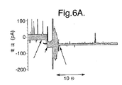
例えば、図6A〜6Dは、脂質二重層9内にポアである膜タンパク質を挿入する間の典型的な電流信号の出力のグラフである。図6A〜6Dの各グラフにおいて、第1矢印は、脂質二重層9に対するゲル14の突出面15の固定が起こった時点を示す。各場合において、この後2〜3秒以内に、電流の急増が起こり、マイナス50mVの電圧の適用下、電流の大きさは0pAから50pAへと増加している。これらのグラフは、環境雑音を減じるために、電気生理学セル1を金属の箱(図示せず)に入れて作成された。しかし、プローブ10を移動させる間、箱が開けられるので、最初の電流信号には非常に雑音が混じる。脂質二重層9内に膜タンパク質が挿入された後、箱が閉じられ、雑音の大きなパルスが引き起こされる。しかしその後は、図6A〜6Dのそれぞれのグラフにおける第2矢印に示されるように、雑音は典型的な量まで急減する。
For example, FIGS. 6A-6D are graphs of typical current signal outputs during the insertion of a pore membrane protein into the
脂質二重層9内に膜タンパク質が挿入された後、プローブ10は、脂質二重層9に固定されたゲル14の突出面15と共に適正な位置に維持される。これは、プローブ10が実施されるべき実験を妨げることがなければ、十分に受け入れられる。この場合、プローブ10のキャリア表面を提供するためのゲル14の使用は特に利点を有する。なぜならば、ゲル14は多孔性であるので、チャンバ部3内の水溶液がゲル14を通過して拡散することを可能にするからである。これは、イオン電流が、ゲル14を通過して膜タンパク質に流れることを可能にする。プローブ10を脂質二重層9に固定させたままにしておくことで、一般的に膜タンパク質が繰り返し挿入されるようになり、過渡的に開くKcsAカリウムチャネルなどのチャネル等のゲーティングにとって利点がある。
After the membrane protein is inserted into the
あるいは、プローブ10を移動させて開口7から遠ざけ、ゲル14の突出面15を脂質二重層9から離脱させてもよい。この場合、膜タンパク質は脂質二重層9内に挿入されたままになっているので、プローブ10のキャリア表面は、脂質二重層9よりも強くない力で、膜タンパク質を保持しなければならない。この要件は、プローブ10のキャリア表面を提供するためにゲル14を使用することによって満たされる。
Alternatively, the
脂質二重層9内に膜タンパク質が挿入された後、問題の膜タンパク質にとって適切な実験工程が、従来の方法で実施されてよい。例えば、確率的センシングを実施するために、電気回路20によって検出される電気信号がモニターされる。
After the membrane protein is inserted into the
ゲル14の突出面15は脂質二重層9に固定されるが、突出面15と脂質二重層9との間の相互作用の明確な性質については、現在知られていない。ゲル14の突出面15が脂質二重層9に非常に近い位置にあることは明確であるが、それらの間に実際の物理的接触があるのかどうか、あるいは、例えば、それらの間に水溶液の薄膜が残っているのかどうかは、明確ではない。とは言え、固定される間、ゲル14が隔壁6に接触することは明白である。従って、ゲル14が柔軟性を有しているので、開口7に適合してその中にわずかに突き出し、脂質二重層9を若干変形させるのではないかと考えられる。
Although the protruding
機械的プロービングの物理的性質が完全には理解されていないという事実はあるものの、脂質二重層9内への膜タンパク質の挿入という観点から見て、この方法は高度に再生産可能であり、信頼性がある。これについては実験的に実証されている。上述の方法全体は、非常に迅速に実施される。この方法は、例えば脂質二重層9を壊して再形成することによって繰り返し実施されてよい。プローブ10上に新しい量の膜タンパク質を堆積させる必要なしに、新しい膜タンパク質が繰り返し挿入され得る。更に注目すべきは、チャンバ部3内の溶液にプローブ10をただ浸したままにしておいて、たとえプローブ10が数時間放置されていたとしても、それによって脂質二重層9内にポアが挿入されてしまうことがないことである。このように、プローブ10を移動して、脂質二重層9に対してキャリア表面を固定させた時のみ、膜タンパク質の挿入が起こる。
In spite of the fact that the physical properties of mechanical probing are not fully understood, this method is highly reproducible and reliable in terms of membrane protein insertion into the
この方法はまた、実施が非常に容易である。プローブ10の単純な手動操作によって、プローブ10が移動され得る。プローブ10の動きを制御するのに、特別な測定の必要はない。実際、この技術的方法は非常に強固であり、脂質二重層9の破裂はめったに起こらない。特に、動作に自動化の必要はないが、もちろんそのような自動化は可能であろう。
This method is also very easy to implement. The
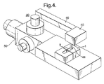
本方法の実施に使用され得る第2装置40が、図4に図示されている。第2装置40は、第1装置30との根本的な相違点を有しており、図5に示されるように、異なる形状のプローブ41が使用される。
A
第2装置40は、第1装置30において使用される電気生理学セル1と実質的に同一の電気生理学セル1を含み、簡潔にするために、その記述は繰り返さない。
The
加えて、第2装置40はプローブ41を含み、プローブ41は、固体材料からなるロッドの形状を有し、緩やかに丸く、プローブ41の側面47と接する端面42を有する。端面42と、側面47の一部は、おそらく分子が脂質二重層9に送達されるようにキャリア表面として作用する。端面42におけるプローブ41の断面は、脂質二重層9よりも小さい。この断面は、好ましくは脂質二重層9の面積の70%を超えず、より好ましくは50%を超えない。なぜならば、隔壁6に隣接する脂質二重層9の外側部は、一般的には、完全に形成されていないからである。従って、プローブ41の端面42が小さいサイズであることにより、膜タンパク質の挿入にとって最良の特性を有する脂質二重層9の中央部と、プローブが一列に配置されることが可能となる。一般的に、プローブ41の端面42の直径は、5μmから50μmの範囲である。
In addition, the
プローブ41は、固体のロッドまたは毛細管であってよいロッド43の先端として形成される。これは、例えば(株)成茂科学器械研究所から容易に入手できる市販の毛細管プーラーを使用して、プローブ41を引っ張ることにより、製造が容易になる。このプーラーの工程を使用するとき、プーラーの設定の制御を通して、プローブ41の形状および鋭さを制御することができる。ロッド43の先端を引っ張ってプローブ41を形成した後、端面42が加熱されて、端面42の粗さが平らにならされる。ロッド43を通過する導管は、引っ張る工程によって閉じられ、本方法においてプローブ41を使用する際に影響はない。
The probe 41 is formed as the tip of a
この製造工程は便利ではあるが、この製造工程およびこれにより得られるプローブ41の性質は必須ではない。一般的に、プローブ41は、脂質二重層9よりも小さい端面を有する任意の形態のプローブと取り替えることが可能である。プローブ41を、たまたま妥当なサイズであることがわかったサボテンの針と取り替えることによって成功した実験の結果も得られている。
This manufacturing process is convenient, but the manufacturing process and the nature of the probe 41 obtained thereby are not essential. In general, the probe 41 can be replaced with any form of probe having an end face smaller than the
プローブ41の端面42は、脂質二重層9に送達される膜タンパク質またはその他の分子に対するプローブ41の材料の親和性を高めるために処理され得る。
The end face 42 of the probe 41 can be treated to increase the affinity of the probe 41 material for membrane proteins or other molecules delivered to the
一つの選択肢は、端面42をコーティングすることによる処理である。一つの可能なコーティングは、ポリエチレンイミン(PEI)の吸着層である。例えばこれは、端面42上にPEI溶液(例えば濃度50%w/w)を適用し、続いて綿棒を使用して、余分なPEIを除去することによって達成され得る。PEIは、αHLなどの負に帯電した膜タンパク質に対する親和性を有利に増加させる。その他の高分子電解質およびその他の材料も同様に適している。
One option is treatment by coating the
別の可能な処理としては、端面42の化学修飾がある。適切な修飾の例としては、アルキルシラン修飾などのシラン修飾が挙げられる。このようなシラン修飾の例は、以下に開示されている:“Silane-modified surfaces for biomaterial immobilization(生体材料の固定化のためのシランで修飾された表面)”、Shriver-Lake、Lisa C.、Naval Research Laboratory、Center for Bio/Molecular Science and Engineering、米国ワシントンDC、Cass,TonlyおよびLigler,Frances S.編、Immobilized Biomolecules in Analysis(1998)、1−14.、Oxford University Press。
Another possible process is chemical modification of the
従って、プローブ41は、機械システムによって操作されることが可能な巨視的な要素である。特に、プローブ41は、以下に述べるようにマイクロマニピュレータ50によって操作される。ロッド43が、ブロック45からぶら下げられたカラム44上に取り付けられ、ブロック45自体がマイクロマニピュレータ50のリンクアーム46に取り付けられる。電気生理学セル1のチャンバ部3内でプローブ41が見えるように、ブロック45は透明である。マイクロマニピュレータ50は、例えば(株)成茂科学器械研究所が供給するもののような、従来型のものである。マイクロマニピュレータ50は、プローブ41の三次元的に制御された動きを提供する。
Accordingly, the probe 41 is a macroscopic element that can be operated by the mechanical system. In particular, the probe 41 is operated by the
以下、第2装置40を使用する方法について述べる。
Hereinafter, a method of using the
留意すべきは、第2装置40のプローブ41のサイズが小さいので、第1装置30のプローブ10に必要とされるよりも、プローブ41の動きに対してより優れた制御が必要とされることである。マイクロマニピュレータ50は、このような制御を提供する。実際、2つのタイプの制御が必要である。
It should be noted that because the size of the probe 41 of the
第1のタイプの制御は、プローブ41を脂質二重層9に平行に動かすことによって、プローブ41を脂質二重層9と一列に整列させるものである。この整列は、例えば電気生理学セル1を明るい光で照らしながらステレオ顕微鏡を使用して、プローブ41が脂質二重層9に向かって動くように見えることで達成することができる。この整列が一度実行された後、この整列を維持するように、マイクロマニピュレータ50の位置の設定が固定される。
The first type of control is to align the probe 41 with the
第2のタイプの制御は、プローブ41が脂質二重層19へ向かう動きの制御である。小さいサイズのプローブ41は、脂質二重層9を有意な量だけ引き伸ばすこと、そしておそらくは、破裂を引き起こすことなく脂質二重層9を貫通することさえも可能にする(ただしこれは現時点では不明である)。
The second type of control is control of the movement of the probe 41 toward the lipid bilayer 19. The small size probe 41 makes it possible to stretch the
端面42が脂質二重層9に固定された際に、動きを止める必要がある。このプローブ41の動きの制御は、初期キャリブレーション工程の実施によって行われ、この工程の間、脂質二重層9の電気容量がモニターされる。電気容量をモニターするために、電極8全域に、従って脂質二重層9全域に、一定の規模の勾配を有するがサインが交互になる振動ランプの形状の電圧波形が適用される。次に出力電流がモニターされる。出力電流の大きさは、電圧信号のランプの勾配(一定である)に比例し、脂質二重層9の電気容量にも比例する。電流は、ランプ電圧のサインが変わるにつれて正電流と負電流の間で変化する。結果として、出力電流信号は、脂質二重層9の電気容量に比例する振幅を有する方形波となる。このようにして、脂質二重層9の電気容量をモニターするために、出力電流信号がモニターされる。
It is necessary to stop the movement when the
キャリブレーション工程の間、プローブ41は、脂質二重層9に向かってゆっくりした速度で動かされる。プローブ41が脂質二重層9に固定されるに至ったとき、これにより、モニターされる電気容量が変化する。これが出力電流信号から検出されると、プローブ41の動きが停止される。この固定の時点において、端面42の少なくとも一部が脂質二重層9に固定される。端面42のより広い面積および側面47の一部までもが脂質二重層9に固定されるように、プローブ41は脂質二重層9を局所的に変形させてよい。
During the calibration process, the probe 41 is moved at a slow speed towards the
プローブ41の位置が留意される。続いて、再び電気容量をモニターする必要なしに、このキャリブレーション工程の間に決定された位置と同じ位置にプローブ41を戻すために、マイクロマニピュレータ50が使用され得る。
The position of the probe 41 is noted. Subsequently, the
マイクロマニピュレータ50は、必要な程度の制御を提供するのに有効ではあるが、このような制御は、その他の方法によって達成してもよい。その他の方法としては、例えば機械的停止装置を使用して、あるいは適切なプログラムを実行するマイクロプロセッサによって制御されたロボットを使用してプローブ41の動きを駆動することなどがある。
Although the
プローブ41を脂質二重層9と一列に整列させ、キャリブレーション工程を実施した後、プローブ41は、膜タンパク質(またはその他のタイプの分子)を脂質二重層9に送達するために、以下のように使用される。
After aligning the probe 41 with the
はじめに、膜タンパク質がプローブ41の端面42上に堆積される。これは、単純にプローブ41の端面42を膜タンパク質の溶液の滴に押し付けることによって達成され得る。これによって、膜タンパク質は端面42上に吸着され、必要なのは少量の溶液のみであるという利点がある。あるいは、例えば第1装置30に関連して上に述べたように、堆積は、任意のその他の方法によって実施され得る。
First, a membrane protein is deposited on the
膜タンパク質の堆積後、プローブ41は、第2装置40内の適切な位置に取り付けられる。次に、上述の従来技術を使用して、脂質二重層9が開口7全体にわたって形成される。
After deposition of the membrane protein, the probe 41 is attached to an appropriate position in the
次に、プローブ42が動かされて脂質二重層9に対してプローブ41の端面42を固定する。このとき、正しい整列を得るために、また、キャリブレーション工程で決定された、0あるいはステレオ顕微鏡で見た正しい位置にプローブ41を移動させるために、マイクロマニピュレータ50を使用する。
Next, the
脂質二重層9に対して端面42を固定させることによって、端面42上に支持された膜タンパク質の脂質二重層9内への挿入が引き起こされる。一般的に、このような挿入は数秒で起こり、第1装置30に関連して上に述べたようにモニターされる。
By immobilizing the
脂質二重層9内に膜タンパク質が挿入された後、プローブ41は、適正な位置に維持されても、第1装置30に関連して上に述べたように脂質二重層9から離脱させてもよい。続いて、問題の膜タンパク質にとって適切な実験工程が、従来の方法で実施されてよい。
After the membrane protein is inserted into the
例として、脂質二重層9内に多数の異なる膜タンパク質を挿入するために、上述の方法が実施されている。以下、図7〜10を参照しつつ、これらの実験の結果を述べる。図7〜10は、それぞれが脂質二重層9内に挿入された異なる膜タンパク質についての電流信号出力のグラフである。
As an example, the above-described method has been implemented to insert a number of different membrane proteins into the
以下の方法を、図1の第1装置30を使用して実施した。
The following method was implemented using the
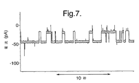
溶液からプローブ10上に堆積されたWT(野生型)αHLタンパク質ポアを挿入するために、前記方法を実施した。検出された電流信号が図7に示されている。マイナス50mVの電流が適用されている。このとき、チャンバ部3において使用された緩衝液は、1M KCl、10mM MOPSでpHは7.00であった。検出された電流信号の形状および信号に係る電流と電圧との関係は、単純に溶液内にタンパク質ポアを配置して挿入を待つという従来技術によって挿入されたものと同じタンパク質ポアを使用して得られたものと区別ができなかった。このタイプのタンパク質ポアは、γ−シクロデキストリンを結合する。結合キネティクスおよびγ−シクロデキストリンの結合における電流の減衰(15μM)については、本方法を使用して挿入されたタンパク質ポアについてものと、従来の方法で挿入されたポアについてのものが同じであった。これらの結果に基づくと、プローブ10の使用により、脂質二重層9または膜タンパク質自体の特性を変えることなしに、膜タンパク質の適切な挿入が達成されることがわかる。
The above method was performed to insert WT (wild type) αHL protein pores deposited on
また、本方法を野生型αHLタンパク質ポアを挿入するために実施し、野生型αHLタンパク質ポアは、第1にrRNA、tRNA、DNA、緩衝液、アミノ酸、リボソームおよび脂質を含有するインビトロ転写/翻訳の混合物内から得られた野生型αHLタンパク質ポアからであり、第2にプローブ10を細菌コロニーにこすりつけることによってプローブ10上に堆積される。後者の場合、界面活性剤および細胞膜を壊すためのその他の成分を含む0.5μLの溶解緩衝液を適用することによって、寒天プレート上に大腸菌の細菌コロニーを溶解させた。どちらの場合においても、図7に示されるものと同様の結果が得られ、それによって、インビトロ転写/翻訳の混合物や細菌コロニーにおけるその他の成分やよりも、野生型αHLタンパク質ポアが挿入されたことの方がより明らかに実証される。
The method is also performed to insert a wild-type αHL protein pore, which is first of all in vitro transcription / translation containing rRNA, tRNA, DNA, buffer, amino acids, ribosomes and lipids. From the wild-type αHL protein pore obtained from within the mixture and secondly deposited on the
また、本方法を野生型KcsAチャネル(ストレプトミセス リビダンス由来のK+チャネル)を挿入するために実施した。このとき、チャンバ部3内の溶液は、100mMのフタル酸カリウムで緩衝化された150mM KClで、pHは4.0であった。図8は、マイナス150mVの電位の適用下でのチャネルゲーティングについての、検出された電流信号を示す。これらチャネルのオープニングのイベントはめったにないので、脂質二重層9内に挿入されるチャネルの数が最大になるように、電気的記録を行う間ずっとプローブ10をそのままにして、ゲル14の突出面15を脂質二重層9に固定させておいた。図8を見ればわかるように、検出された電流信号は、チャネルのオープニングの特性である事象を示す。
This method was also performed to insert a wild type KcsA channel (K + channel derived from Streptomyces lividans). At this time, the solution in the
続いて、プローブ10を移動させて、ゲル14の突出面15を脂質二重層9から離脱させた。このとき、検出された電流信号において、同じ事象が観察された。このことに基づくと、ゲル14の突出面15を脂質二重層9に固定させても、実験工程を妨げなかったことがわかる。
Subsequently, the
また、本方法を、pHが7.00の緩衝液1M KCl、10mM MOPSを使用してロイコシジンのポアを挿入するために実施した。プローブ10を離脱させた後に検出された電流信号が図9に示されている。適用された電位はマイナス40mVであった。検出された電流信号のレベルは、ポアが開いていることを示している。
The method was also performed to insert a pore of leucocidin using buffer 1M KCl, 10 mM MOPS, pH 7.00. The current signal detected after the
以下の方法は、図4の第2装置40を使用して実施され、ハイスループットなスクリーニングに適用された際の前記方法の有効性を実証する。
The following method is performed using the
前記方法を、寒天プレート上に堆積されたαHLを発現する細菌コロニー由来のαHLタンパク質ポアを挿入するために実施した。毎回、プレートには100個のコロニーを配置し、そのうちの約95〜99個のコロニーが野生型αHLを発現し、残りのものがαHLの変異体、M113F/K 147Nを発現した。異なるタイプのコロニーの数および位置は、プレートスクリーナーでは明らかにされなかった。前記方法は、各コロニーについて実施した。αHLタンパク質ポアを、プローブをコロニーにこすりつけることによってプローブ上に堆積した。
The method was performed to insert an αHL protein pore from a bacterial colony expressing αHL deposited on an agar plate. Each
タンパク質は細菌の細胞質内で発現されたが、コロニーを溶解または化学的に処理する必要はなかった。自然に溶解したコロニー内の細菌の画分によって、十分なタンパク質が供給されたようであった。プローブの先端は、コロニーをスクリーニングした後で、新しい寒天内を引っ張って通過させることによりクリーニングすることが可能であった。また、クリーニングされた先端は、ポアを産生しなかった。 Although the protein was expressed in the bacterial cytoplasm, it was not necessary to lyse or chemically treat the colonies. Sufficient protein appeared to be supplied by the bacterial fraction within the naturally lysed colonies. The tip of the probe could be cleaned by pulling through a fresh agar after screening the colonies. Also, the cleaned tip did not produce pores.
タンパク質ポアを脂質二重層9内に挿入し、検出された電流信号をモニターした。ポアからの記録後、次の試料に移る前にセル1をクリーニングする必要はなかった。その代わりに、脂質二重層9を壊して再形成することによってシステムをリセットした。これらの操作は、スクリーニングのスピードを改善した。
A protein pore was inserted into the
プローブ41は、マイクロマニピュレータ50に固定し、セル1のシス(cis)側チャンバ部3内に沈め、脂質二重層9に固定した。プローブ41は、記録する間、脂質二重層9に固定させることが可能であった。単一のポア、または複数のポアを挿入するために必要な時間は変化した。異なるコロニーからのタンパク質の入手可能度は一貫していなかった。概して、αHLコロニー(野生型または変異体)は強力であった。つまり、プローブ41の脂質二重層9への固定がたとえ短い時間であっても(〜0.5秒)、複数のポアの挿入が引き起こされた。これらのコロニー由来の単一のポアを記録するために、脂質二重層9を電気パルスで壊し、再形成し、プローブ41を再度固定した。プローブ41上のポア形成タンパク質の量が、単一のポアの挿入が可能になるのに十分な程度減少するまで、この工程を繰り返した。プローブ41の固定/離脱および脂質二重層9の再形成は、1分当たり少なくとも5回繰り返すことができた。しかし、一般的に、単一の機能的なポアを得るために必要な繰り返し回数は、2〜4回のみである。
The probe 41 was fixed to the
検出された電流信号によって、2つのタイプのαHLタンパク質ポアの区別が可能となった。両方のタイプのαHLが、類似のイオン伝導度を有するポアを形成する。しかし、変異体αHLのみが、シス(cis)側由来の分子アダプターβCDを結合する。プレートはプローブ法によってスクリーニングされた。シス(cis)側およびトランス(trans)側のチャンバ部3の両方が、10mM MOPS、1M KClを含有し、pHは7.0であった。脂質二重層9は−50mVで保持された。記録は、シス(cis)側のチャンバ部3内において、90μMのβCDで行われた。βCDは変異体のポアに結合したが、野生型のポアには結合しなかった。
The detected current signal made it possible to distinguish between the two types of αHL protein pores. Both types of αHL form pores with similar ionic conductivity. However, only mutant αHL binds the molecular adapter βCD from the cis side. Plates were screened by the probe method. Both the cis side and trans
野生型のαHLは、二重層内に挿入された各ポアについて、電流の段階的な増加を示した。4つのポアの場合の例が図10Aに示される。しかし、M113F/K147N変異体がβCDを結合し、電流の特性の減衰を与えている。2つのポアの場合の例が図10Bに示される。100個のコロニー全てをスクリーニングした後、プレートの作製者がその後明らかにした位置に厳密に対応する位置において、変異体を発現するコロニーが発見された。 Wild-type αHL showed a gradual increase in current for each pore inserted in the bilayer. An example with four pores is shown in FIG. 10A. However, the M113F / K147N mutant binds βCD, giving an attenuation of the current characteristic. An example with two pores is shown in FIG. 10B. After screening all 100 colonies, a colony expressing the mutant was found at a position that exactly corresponds to the position subsequently revealed by the plate creator.
この実験は、野生型ポアのバックグラウンドにおける新しい機能のまれな場合の迅速なスクリーニングを実証している。 This experiment demonstrates a rare and rapid screening of new functions in the background of wild-type pores.
次に、活性なタンパク質ポア、特に、2つの異なるモノマーから構成され、4つのLuk Fサブユニットおよび4つのLuk Sサブユニットが中心軸の周囲に交互に配置されて八量体のポアを与えるロイコシジンを産生するために組み合わされる2つのタンパク質のサブユニットを堆積するために、前記方法を実施した。 Next, an active protein pore, in particular leukocidin composed of two different monomers, with four Luk F subunits and four Luk S subunits arranged alternately around the central axis to give an octameric pore The method was performed to deposit two protein subunits that were combined to produce.
野生型Luk Fおよび野生型Luk Sを発現する別々の大腸菌コロニーを寒天プレートからこすり取り、新鮮な寒天の表面上に共に配置し、外科用メスの刀で完全に混合したが、溶解はしなかった。注目すべきことに、プローブ41を細菌の混合物の中に浸して脂質二重層9に固定し、野生型ロイコシジンのポアを産生することが可能であることが発見された。このように、精製することなく、別々の成分由来の完全に機能的な2成分の膜のポアを組み立てることが可能であった。単一のロイコシジンのポアの挿入には、通常、αHLコロニーの場合よりもより長い時間のプローブの固定を必要とした。ロイコシジンは、溶血アッセイにおいてαHLよりも活性がはるかに低いので、このことは予期されるであろう。一般的に、新たに混合されたコロニーを使用すると、プローブ41は、単一のポアが挿入される前に数秒間、脂質二重層9に固定しておいた。しかし、混合されたコロニーは、時間の経過によりしばしばより強力になり、1秒当たりにαHLコロニーと同等の量のポアを産生するものもあった。ロイコシジンのコロニーの混合物は、寒天プレート上で少なくとも1ヶ月間、4℃で保存でき、依然としてプローブ法によってタンパク質ポアを生産することができた。
Separate E. coli colonies expressing wild-type Luk F and wild-type Luk S were scraped from the agar plate and placed together on a fresh agar surface and mixed thoroughly with a scalpel with a scalpel but did not lyse It was. Of note, it has been discovered that the probe 41 can be immersed in a mixture of bacteria and immobilized on the
これまでに、αHLのβ−バレル型におけるあるアミノ酸が、βCDの結合を強化するために変異可能なことが示されている(αHLとβCDの両方が7回折り畳み軸対称を有する)。 To date, it has been shown that certain amino acids in the β-barrel form of αHL can be mutated to enhance βCD binding (both αHL and βCD have 7-fold axial symmetry).
例えば、αHLのM113残基がフェニルアラニンに変異された場合、βCDの結合の持続時間は、野生型のαHLと比較すると最大で3×10⁴倍長い。βCDの過メチル化形態であるTRIMEBは、βCDよりも最大で4倍長い時間、M113F αHLに結合する。これらの知見に基づくと、変異タンパク質が過メチル化されたγCDであるTRIMEGと結合するように(ロイコシジンとTRIMEGの両方が8倍の軸対称を有する)、ロイコシジンのβ−バレル型において同様の変異を行い得ると仮定した。 For example, when the MHL residue of αHL is mutated to phenylalanine, the duration of βCD binding is up to 3 × 10 4 times longer than wild type αHL. TRIMEB, a hypermethylated form of βCD, binds to M113F αHL for up to 4 times longer than βCD. Based on these findings, similar mutations in the β-barrel form of leukocidin so that the mutant protein binds to TRIMEG, which is a hypermethylated γCD (both leukocidin and TRIMEG have eightfold axial symmetry). Was assumed to be possible.
配列相同性、αHL7量体の結晶構造、そしてLuk F(HlgB)、Luk F(PV)およびLuk S(PV)モノマーそれぞれの結晶構造に基づいて、バレルのβ鎖内のアミノ酸の配列を、3つのモノマーすべてについてモデル化した。変異を行い、Luk FおよびLuk Sのβ鎖に沿った多様な位置における天然のアミノ酸を、フェニルアラニンで置換した。β−バレル型の内部では、変異された残基が整列して、8個のフェニルアラニンの環が1つ、または4個のフェニルアラニンの環が別々に2つ、形成することができた。αHL M113Fから類推して、整列したフェニルアラニン残基が、TRIMEGを結合するロイコシジンの形態を作り出すと仮定された。 Based on the sequence homology, the crystal structure of the αHL heptamer, and the crystal structure of each of the Luk F (HlgB), Luk F (PV) and Luk S (PV) monomers, the sequence of amino acids in the β chain of the barrel Modeled for all two monomers. Mutations were performed to replace the natural amino acid at various positions along the Luk F and Luk S β chains with phenylalanine. Within the β-barrel form, the mutated residues were aligned to form one 8 phenylalanine ring or two separate 4 phenylalanine rings. By analogy with αHL M113F, it was hypothesized that aligned phenylalanine residues create a form of leukocidin that binds TRIMEG.
以前は、IVTTによって、Luk FおよびLuk Sの個々のモノマーを発現させることにより、変異ロイコシジンを作製した。モノマーがウサギの赤血球膜上で組み立てて8量体を得た。続いて8量体をゲル精製にかけた。 Previously, mutant leukocidin was generated by expressing individual monomers of Luk F and Luk S by IVTT. Monomers were assembled on rabbit erythrocyte membranes to give octamers. Subsequently, the octamer was subjected to gel purification.
一方、本発明の方法においては、変異サブユニットから機能的なロイコシジンのポアを得るために、はるかに迅速なプローブの手順を使用した。2つのサブユニットの35通りの新しい組合せそれぞれについて、3つの個々のポアが試験され、動的データが平均化された。Luk F Q112F/Luk S S108 Fの組合せが、他の組合せよりも少なくとも2桁分長い時間、TRIMEGと結合した一方で、野生型のロイコシジンがTRIMEGと結合した時間は最も短かった。これらのデータは、M113、Q112およびS108におけるアミノ酸が、αHL、Luk FおよびLuk S内それぞれにおいて、同じ位置および配向を共有することを示唆する。 On the other hand, in the method of the present invention, a much faster probe procedure was used to obtain a functional leukocidin pore from the mutant subunit. For each of the 35 new combinations of two subunits, three individual pores were tested and the dynamic data was averaged. The Luk F Q112F / Luk S S108 F combination bound to TRIMEG for at least two orders of magnitude longer than the other combinations, while the wild-type leukocidin bound to TRIMEG was the shortest. These data suggest that the amino acids in M113, Q112 and S108 share the same position and orientation within αHL, Luk F and Luk S, respectively.
この実験は、コロニー由来のβPFTが単量体であるという考えを支持する。この場合、水溶性モノマーは、混合後に組み立てなければならない。これらの実験において使用される細菌株は、内因性膜のチャネルおよびポアを有していなければならない。しかし、これらによる妨げは、電気的記録においては観察されなかった。過剰発現したタンパク質の細菌コロニーから平面二十層への移送は非効率的であり、当然、内因性タンパク質の挿入が起きる頻度が低いであろうと予測される。非効率的な移送は、バルクアッセイにおいては望ましくないであろうが、その一方で、単一のチャネルの記録によるスクリーニングには理想的に適合する。 This experiment supports the idea that colony-derived βPFT is a monomer. In this case, the water-soluble monomer must be assembled after mixing. The bacterial strain used in these experiments must have intrinsic membrane channels and pores. However, these disturbances were not observed in electrical recording. Transfer of overexpressed proteins from the bacterial colony to the planar twentieth layer is inefficient, and of course, it is expected that the frequency of endogenous protein insertion will be low. Inefficient transfer would not be desirable in a bulk assay, while ideally suited for screening with single channel recording.
大量のデータ収集は、別のアプローチでは多くの時間と労力を要したであろうが、複数のLukコロニーを混合してガラス製プローブに適用したことにより、効率的なスクリーニングが可能となった。このことは、本発明の有効性がハイスループットなスクリーニングを可能にすることをはっきりと実証している。 Large amounts of data collection would have taken a lot of time and effort in another approach, but mixing multiple Luk colonies and applying them to glass probes enabled efficient screening. This clearly demonstrates that the effectiveness of the present invention enables high throughput screening.
上述の報告された実験結果は、膜タンパク質の主要な2つのクラスの例に関する挿入を実証する。すなわちβ−バレル型(例えばαHLのポアおよびロイコシジンのポア)およびα−ヘリックス型(例えばK+チャネル)は、本発明の方法を使用して挿入することができる。このことに基づいて、任意の膜タンパク質が、平面脂質二重層9内に同様に挿入できることがわかる。前記方法により、不溶性の膜タンパク質を含有する、細胞溶解物または画分を含む任意の材料を、天然環境から脂質二重層9へと直接送達することができると予想される。
The reported experimental results described above demonstrate insertion for two major classes of examples of membrane proteins. That is, β-barrel types (eg, αHL pores and leukocidin pores) and α-helix types (eg, K + channels) can be inserted using the methods of the present invention. Based on this, it can be seen that any membrane protein can be similarly inserted into the
Claims (29)
手動または機械システムによって移動可能に配置された巨視的な要素であり、かつ前記膜タンパク質の保持が可能なキャリア表面を有する、プローブを提供する工程と、
膜タンパク質がキャリア表面上に保持されるように前記プローブのキャリア表面上に前記膜タンパク質を堆積させる工程と、
手動または機械システムによって前記プローブを移動させ前記平面脂質二重層に対して前記キャリア表面を固定し、前記膜タンパク質を前記脂質二重層へ挿入させ前記電気回路によって測定される電気信号に基づき前記挿入が検出される工程と、
を含む方法。 A method for inserting a membrane protein into a planar lipid bilayer using an apparatus having an electrical circuit capable of measuring an electrical signal in the planar lipid bilayer,
Providing a probe having a carrier surface that is a macroscopic element arranged movably by a manual or mechanical system and capable of retaining the membrane protein;
Depositing the membrane protein on the carrier surface of the probe such that the membrane protein is retained on the carrier surface;
The probe is moved manually or by a mechanical system to immobilize the carrier surface relative to the planar lipid bilayer, the membrane protein is inserted into the lipid bilayer, and the insertion is performed based on an electrical signal measured by the electrical circuit. Detected steps;
Including methods.
前記方法は更に、前記プローブを移動させ、平面脂質二重層に対してプローブのキャリア表面を固定する工程の後に、前記プローブを移動させて、平面脂質二重層からプローブのキャリア表面を離脱させ、それによって、挿入された膜タンパク質を平面脂質二重層内に残す工程を含む請求項1記載の方法。 The carrier surface may be the planar lipid bilayer holding the membrane protein less strong force than the force holding the membrane protein,
The method further includes moving the probe and immobilizing the probe carrier surface relative to the planar lipid bilayer, and then moving the probe to disengage the probe carrier surface from the planar lipid bilayer; 2. The method of claim 1 comprising the step of leaving the inserted membrane protein in the planar lipid bilayer.
前記プローブが、
前記キャリア表面を有する本体と、
前記チャンバ内の本体を支持し、前記開口部を通して前記チャンバの外に伸張し前記プローブの操作を可能にするアームとを含む請求項24〜26のいずれかに記載の方法。 The chamber has an opening on an upper surface of the chamber, and the wall has an opening formed on a side surface of the chamber;
The probe is
A body having the carrier surface;
The method according to any one of claims 24-26, wherein the main body and the support of the chamber, extends out of the chamber through the opening includes an arm that allows the manipulation of the probe.
Applications Claiming Priority (3)
| Application Number | Priority Date | Filing Date | Title |
|---|---|---|---|
| GB0505971.2 | 2005-03-23 | ||
| GBGB0505971.2A GB0505971D0 (en) | 2005-03-23 | 2005-03-23 | Delivery of molecules to a lipid bilayer |
| PCT/GB2006/001057 WO2006100484A2 (en) | 2005-03-23 | 2006-03-22 | Deliver of molecules to a li id bila |
Publications (3)
| Publication Number | Publication Date |
|---|---|
| JP2008537106A JP2008537106A (en) | 2008-09-11 |
| JP2008537106A5 JP2008537106A5 (en) | 2009-10-15 |
| JP5253148B2 true JP5253148B2 (en) | 2013-07-31 |
Family
ID=34531741
Family Applications (1)
| Application Number | Title | Priority Date | Filing Date |
|---|---|---|---|
| JP2008502471A Expired - Fee Related JP5253148B2 (en) | 2005-03-23 | 2006-03-22 | Delivery of molecules to the lipid bilayer |
Country Status (7)
| Country | Link |
|---|---|
| US (1) | US7939270B2 (en) |
| EP (1) | EP1861071B1 (en) |
| JP (1) | JP5253148B2 (en) |
| AT (1) | ATE473438T1 (en) |
| DE (1) | DE602006015292D1 (en) |
| GB (1) | GB0505971D0 (en) |
| WO (1) | WO2006100484A2 (en) |
Cited By (1)
| Publication number | Priority date | Publication date | Assignee | Title |
|---|---|---|---|---|
| US8627531B2 (en) | 2001-09-04 | 2014-01-14 | Sharp Kabushiki Kaisha | Vacuum cleaner and device having ion generator |
Families Citing this family (145)
| Publication number | Priority date | Publication date | Assignee | Title |
|---|---|---|---|---|
| US9233846B2 (en) | 2005-10-14 | 2016-01-12 | The Regents Of The University Of California | Formation and encapsulation of molecular bilayer and monolayer membranes |
| GB0523282D0 (en) | 2005-11-15 | 2005-12-21 | Isis Innovation | Methods using pores |
| US9415422B2 (en) | 2006-03-10 | 2016-08-16 | Siemens Industry, Inc. | Mail sorting system |
| WO2007146158A1 (en) * | 2006-06-07 | 2007-12-21 | The Trustees Of Columbia University In The City Of New York | Dna sequencing by nanopore using modified nucleotides |
| US20100196203A1 (en) * | 2007-02-20 | 2010-08-05 | Gurdial Singh Sanghera | Formation of Lipid Bilayers |
| GB2447043A (en) * | 2007-02-20 | 2008-09-03 | Oxford Nanolabs Ltd | Lipid bilayer sensor system |
| GB2446823A (en) * | 2007-02-20 | 2008-08-27 | Oxford Nanolabs Ltd | Formulation of lipid bilayers |
| US20110005918A1 (en) | 2007-04-04 | 2011-01-13 | Akeson Mark A | Compositions, devices, systems, and methods for using a nanopore |
| GB0716264D0 (en) | 2007-08-21 | 2007-09-26 | Isis Innovation | Bilayers |
| GB2453377A (en) | 2007-10-05 | 2009-04-08 | Isis Innovation | Transmembrane protein pores and molecular adapters therefore. |
| US8124191B2 (en) * | 2007-11-30 | 2012-02-28 | Electronic Bio Sciences, Llc | Method and apparatus for single side bilayer formation |
| GB0724736D0 (en) | 2007-12-19 | 2008-01-30 | Oxford Nanolabs Ltd | Formation of layers of amphiphilic molecules |
| WO2009143425A1 (en) * | 2008-05-22 | 2009-11-26 | The Regents Of The University Of California | Membrane precursors and membranes formed therefrom |
| US20110229877A1 (en) | 2008-07-07 | 2011-09-22 | Oxford Nanopore Technologies Limited | Enzyme-pore constructs |
| GB0820927D0 (en) | 2008-11-14 | 2008-12-24 | Isis Innovation | Method |
| EP2391655B1 (en) | 2009-01-30 | 2017-10-11 | Oxford Nanopore Technologies Limited | Hybridization linkers |
| CA2750879C (en) | 2009-01-30 | 2018-05-22 | Oxford Nanopore Technologies Limited | Adaptors for nucleic acid constructs in transmembrane sequencing |
| GB0905140D0 (en) | 2009-03-25 | 2009-05-06 | Isis Innovation | Method |
| US9678055B2 (en) | 2010-02-08 | 2017-06-13 | Genia Technologies, Inc. | Methods for forming a nanopore in a lipid bilayer |
| US8324914B2 (en) | 2010-02-08 | 2012-12-04 | Genia Technologies, Inc. | Systems and methods for characterizing a molecule |
| US9605307B2 (en) | 2010-02-08 | 2017-03-28 | Genia Technologies, Inc. | Systems and methods for forming a nanopore in a lipid bilayer |
| US20140051068A1 (en) | 2010-09-07 | 2014-02-20 | The Regents Of The University Of California | Control of dna movement in a nanopore at one nucleotide precision by a processive enzyme |
| CN103282518B (en) | 2010-12-17 | 2016-11-16 | 纽约哥伦比亚大学理事会 | Use synthesis limit, the DNA limit order-checking of modified nucleotide and nano-pore detection |
| US8845880B2 (en) | 2010-12-22 | 2014-09-30 | Genia Technologies, Inc. | Nanopore-based single DNA molecule characterization, identification and isolation using speed bumps |
| GB201100516D0 (en) | 2011-01-12 | 2011-02-23 | Isis Innovation | Method using fluorinated amphiphiles |
| US8962242B2 (en) | 2011-01-24 | 2015-02-24 | Genia Technologies, Inc. | System for detecting electrical properties of a molecular complex |
| US9110478B2 (en) | 2011-01-27 | 2015-08-18 | Genia Technologies, Inc. | Temperature regulation of measurement arrays |
| CN103460040B (en) | 2011-02-11 | 2016-08-17 | 牛津纳米孔技术有限公司 | Saltant type hole |
| US8968539B2 (en) | 2011-03-08 | 2015-03-03 | Electronic Biosciences, Inc. | Methods for voltage-induced protein incorporation into planar lipid bilayers |
| EP3633370A1 (en) | 2011-05-27 | 2020-04-08 | Oxford Nanopore Technologies Limited | Coupling method |
| CN103827320B (en) | 2011-07-25 | 2017-04-26 | 牛津纳米孔技术有限公司 | Hairpin loop method for double strand polynucleotide sequencing using transmembrane pores |
| US9150598B2 (en) * | 2011-10-05 | 2015-10-06 | The Regents Of The University Of California | Masking apertures enabling automation and solution exchange in sessile bilayers |
| BR112014009579B1 (en) | 2011-10-21 | 2021-06-22 | Oxford Nanopore Technologies Limited | METHODS FOR CHARACTERIZING A TARGET POLYNUCLEOTIDE, AND FOR FORMING A SENSOR, USE OF A HELICASE, KIT, AND, ANALYSIS APPARATUS |
| GB201119032D0 (en) | 2011-11-03 | 2011-12-14 | Isis Innovation | Multisomes: encapsulated droplet networks |
| WO2013098562A2 (en) | 2011-12-29 | 2013-07-04 | Oxford Nanopore Technologies Limited | Enzyme method |
| EP2798083B1 (en) | 2011-12-29 | 2017-08-09 | Oxford Nanopore Technologies Limited | Method for characterising a polynucelotide by using a xpd helicase |
| GB201202519D0 (en) | 2012-02-13 | 2012-03-28 | Oxford Nanopore Tech Ltd | Apparatus for supporting an array of layers of amphiphilic molecules and method of forming an array of layers of amphiphilic molecules |
| JP6275052B2 (en) | 2012-02-15 | 2018-02-07 | オックスフォード ナノポール テクノロジーズ リミテッド | Aptamer method |
| BR112014020211A2 (en) | 2012-02-16 | 2017-07-04 | Oxford Nanopore Tech Ltd | methods for analyzing a time-ordered series of polymer measurements, for estimating the presence, absence, or amount of a target polymer, and for determining a change in a polymer, computer program, and diagnostic and diagnostic devices. |
| US8986629B2 (en) | 2012-02-27 | 2015-03-24 | Genia Technologies, Inc. | Sensor circuit for controlling, detecting, and measuring a molecular complex |
| EP2836604B1 (en) | 2012-04-09 | 2021-09-15 | The Trustees of Columbia University in the City of New York | Method of preparation of nanopore and uses thereof |
| WO2013153359A1 (en) | 2012-04-10 | 2013-10-17 | Oxford Nanopore Technologies Limited | Mutant lysenin pores |
| EP2861768A4 (en) | 2012-06-15 | 2016-03-02 | Genia Technologies Inc | Chip set-up and high-accuracy nucleic acid sequencing |
| EP3674412A1 (en) | 2012-06-20 | 2020-07-01 | The Trustees of Columbia University in the City of New York | Nucleic acid sequencing by nanopore detection of tag molecules |
| EP2875154B1 (en) | 2012-07-19 | 2017-08-23 | Oxford Nanopore Technologies Limited | SSB method for characterising a nucleic acid |
| AU2013291765C1 (en) | 2012-07-19 | 2019-08-08 | Oxford Nanopore Technologies Limited | Enzyme construct |
| AU2013291763B2 (en) | 2012-07-19 | 2019-06-20 | Oxford Nanopore Technologies Limited | Modified helicases |
| WO2014041337A1 (en) | 2012-09-14 | 2014-03-20 | Oxford Nanopore Technologies Limited | Sample preparation method |
| GB201219201D0 (en) | 2012-10-25 | 2012-12-12 | Isis Innovation | Hydrogel network |
| GB201219196D0 (en) | 2012-10-25 | 2012-12-12 | Isis Innovation | Droplet assembly method |
| GB201313121D0 (en) | 2013-07-23 | 2013-09-04 | Oxford Nanopore Tech Ltd | Array of volumes of polar medium |
| US9823235B2 (en) | 2012-10-26 | 2017-11-21 | Oxford Nanopre Technologies Ltd. | Droplet interfaces |
| WO2014072703A1 (en) | 2012-11-06 | 2014-05-15 | Oxford Nanopore Technologies Limited | Quadruplex method |
| US9605309B2 (en) | 2012-11-09 | 2017-03-28 | Genia Technologies, Inc. | Nucleic acid sequencing using tags |
| JP6416772B2 (en) * | 2012-12-07 | 2018-10-31 | オックスフォード ユニヴァーシティ イノヴェーション リミテッド | Droplet collection by 3D printing |
| GB201222928D0 (en) | 2012-12-19 | 2013-01-30 | Oxford Nanopore Tech Ltd | Analysis of a polynucleotide |
| EP2746772B1 (en) | 2012-12-20 | 2016-03-23 | AIT Austrian Institute of Technology GmbH | Lipid membrane enveloped particles with membrane proteins |
| US9759711B2 (en) | 2013-02-05 | 2017-09-12 | Genia Technologies, Inc. | Nanopore arrays |
| GB201314695D0 (en) | 2013-08-16 | 2013-10-02 | Oxford Nanopore Tech Ltd | Method |
| GB201318465D0 (en) | 2013-10-18 | 2013-12-04 | Oxford Nanopore Tech Ltd | Method |
| JP6408494B2 (en) | 2013-03-08 | 2018-10-17 | オックスフォード ナノポール テクノロジーズ リミテッド | Enzyme stop method |
| CN105102627B (en) | 2013-03-15 | 2018-10-19 | 纽约哥伦比亚大学理事会 | Method for detecting a variety of predetermined compounds in sample |
| GB201313477D0 (en) | 2013-07-29 | 2013-09-11 | Univ Leuven Kath | Nanopore biosensors for detection of proteins and nucleic acids |
| GB201316849D0 (en) | 2013-09-23 | 2013-11-06 | Isis Innovation | Method |
| US9551697B2 (en) | 2013-10-17 | 2017-01-24 | Genia Technologies, Inc. | Non-faradaic, capacitively coupled measurement in a nanopore cell array |
| EP3575410A3 (en) | 2013-10-18 | 2020-03-04 | Oxford Nanopore Technologies Limited | Modified enzymes |
| GB201406151D0 (en) | 2014-04-04 | 2014-05-21 | Oxford Nanopore Tech Ltd | Method |
| US9322062B2 (en) | 2013-10-23 | 2016-04-26 | Genia Technologies, Inc. | Process for biosensor well formation |
| EP3640349A3 (en) | 2013-10-23 | 2020-07-29 | Roche Sequencing Solutions, Inc. | High speed molecular sensing with nanopores |
| ES2958715T3 (en) | 2013-11-26 | 2024-02-13 | Illumina Inc | Compositions and methods for polynucleotide sequencing |
| EP2886663A1 (en) | 2013-12-19 | 2015-06-24 | Centre National de la Recherche Scientifique (CNRS) | Nanopore sequencing using replicative polymerases and helicases |
| GB201406155D0 (en) | 2014-04-04 | 2014-05-21 | Oxford Nanopore Tech Ltd | Method |
| WO2015110813A1 (en) | 2014-01-22 | 2015-07-30 | Oxford Nanopore Technologies Limited | Method for attaching one or more polynucleotide binding proteins to a target polynucleotide |
| GB201403096D0 (en) | 2014-02-21 | 2014-04-09 | Oxford Nanopore Tech Ltd | Sample preparation method |
| CA2943952A1 (en) | 2014-03-24 | 2015-10-01 | The Trustees Of Columbia University In The City Of New York | Chemical methods for producing tagged nucleotides |
| WO2015150786A1 (en) | 2014-04-04 | 2015-10-08 | Oxford Nanopore Technologies Limited | Method for characterising a double stranded nucleic acid using a nano-pore and anchor molecules at both ends of said nucleic acid |
| GB201417712D0 (en) | 2014-10-07 | 2014-11-19 | Oxford Nanopore Tech Ltd | Method |
| EP3137627A1 (en) | 2014-05-02 | 2017-03-08 | Oxford Nanopore Technologies Limited | Method of improving the movement of a target polynucleotide with respect to a transmembrane pore |
| WO2016019030A1 (en) | 2014-07-31 | 2016-02-04 | Illumina, Inc. | Hybrid nanopore sensors |
| WO2016034591A2 (en) | 2014-09-01 | 2016-03-10 | Vib Vzw | Mutant pores |
| WO2016055778A1 (en) | 2014-10-07 | 2016-04-14 | Oxford Nanopore Technologies Limited | Mutant pores |
| GB201418159D0 (en) | 2014-10-14 | 2014-11-26 | Oxford Nanopore Tech Ltd | Method |
| CN107109490B (en) | 2014-10-16 | 2022-12-02 | 牛津楠路珀尔科技股份有限公司 | Analysis of polymers |
| GB201418469D0 (en) | 2014-10-17 | 2014-12-03 | Oxford Nanopore Tech Ltd | Method |
| GB201418512D0 (en) | 2014-10-17 | 2014-12-03 | Oxford Nanopore Tech Ltd | Electrical device with detachable components |
| RU2732925C2 (en) | 2015-01-26 | 2020-09-24 | Селлектис | Mat-directed chimeric antigen receptor systems for sorting/depleting the engineered immune cells |
| GB201502810D0 (en) | 2015-02-19 | 2015-04-08 | Oxford Nanopore Tech Ltd | Method |
| GB201502809D0 (en) | 2015-02-19 | 2015-04-08 | Oxford Nanopore Tech Ltd | Mutant pore |
| WO2016166232A1 (en) | 2015-04-14 | 2016-10-20 | Katholieke Universiteit Leuven | Nanopores with internal protein adaptors |
| KR20180089499A (en) | 2015-12-08 | 2018-08-08 | 카트호리이케 유니버시타이트 로이펜 | Modified nanopores, compositions comprising same, and uses thereof |
| KR102222191B1 (en) | 2016-03-02 | 2021-03-02 | 옥스포드 나노포어 테크놀로지즈 리미티드 | Mutant pore |
| JP7364333B2 (en) | 2016-04-06 | 2023-10-18 | オックスフォード ナノポール テクノロジーズ ピーエルシー | mutant pore |
| GB201609221D0 (en) | 2016-05-25 | 2016-07-06 | Oxford Nanopore Tech Ltd | Method |
| EP3464616B1 (en) | 2016-05-25 | 2022-05-04 | Oxford Nanopore Technologies plc | Method |
| GB201609220D0 (en) | 2016-05-25 | 2016-07-06 | Oxford Nanopore Tech Ltd | Method |
| GB201611770D0 (en) | 2016-07-06 | 2016-08-17 | Oxford Nanopore Tech | Microfluidic device |
| GB201616590D0 (en) | 2016-09-29 | 2016-11-16 | Oxford Nanopore Technologies Limited | Method |
| JP2018059786A (en) * | 2016-10-04 | 2018-04-12 | 住友化学株式会社 | Device and method for detecting target material using olfactory receptor complex and method for manufacturing the detector |
| GB201617886D0 (en) | 2016-10-21 | 2016-12-07 | Oxford Nanopore Technologies Limited | Method |
| GB201620450D0 (en) | 2016-12-01 | 2017-01-18 | Oxford Nanopore Tech Ltd | Method |
| CN110267974A (en) | 2017-02-10 | 2019-09-20 | 牛津纳米孔技术公司 | The nano-pore of modification includes its composition and application thereof |
| GB201707122D0 (en) | 2017-05-04 | 2017-06-21 | Oxford Nanopore Tech Ltd | Pore |
| GB201707140D0 (en) | 2017-05-04 | 2017-06-21 | Oxford Nanopore Tech Ltd | Method |
| CN110914290A (en) | 2017-06-30 | 2020-03-24 | 弗拉芒区生物技术研究所 | Novel protein pores |
| EP4303317A2 (en) * | 2017-10-23 | 2024-01-10 | F. Hoffmann-La Roche AG | Removing and reinserting protein nanopores in a membrane using osmotic imbalance |
| GB201807793D0 (en) | 2018-05-14 | 2018-06-27 | Oxford Nanopore Tech Ltd | Method |
| GB201808556D0 (en) | 2018-05-24 | 2018-07-11 | Oxford Nanopore Tech Ltd | Method |
| GB201809323D0 (en) | 2018-06-06 | 2018-07-25 | Oxford Nanopore Tech Ltd | Method |
| GB201811623D0 (en) | 2018-07-16 | 2018-08-29 | Univ Oxford Innovation Ltd | Molecular hopper |
| WO2020025909A1 (en) | 2018-07-30 | 2020-02-06 | Oxford University Innovation Limited | Assemblies |
| GB201818216D0 (en) | 2018-11-08 | 2018-12-26 | Oxford Nanopore Tech Ltd | Pore |
| WO2020095052A1 (en) | 2018-11-08 | 2020-05-14 | Oxford Nanopore Technologies Limited | Pore |
| GB201821155D0 (en) | 2018-12-21 | 2019-02-06 | Oxford Nanopore Tech Ltd | Method |
| EP3938779A1 (en) | 2019-03-12 | 2022-01-19 | Oxford Nanopore Technologies Limited | Nanopore sensing device and methods of operation and of forming it |
| GB2580988B (en) | 2019-03-19 | 2022-04-13 | Oxford Nanopore Tech Ltd | Current measurement apparatus, molecular entity sensing apparatus, method of measuring a current, method of sensing a molecular entity |
| CN113677693A (en) | 2019-04-09 | 2021-11-19 | 牛津纳米孔科技公司 | Hole(s) |
| GB201907244D0 (en) | 2019-05-22 | 2019-07-03 | Oxford Nanopore Tech Ltd | Method |
| GB201907246D0 (en) | 2019-05-22 | 2019-07-03 | Oxford Nanopore Tech Ltd | Method |
| GB201913997D0 (en) | 2019-09-27 | 2019-11-13 | Oxford Nanopore Tech Ltd | Method |
| GB201915480D0 (en) | 2019-10-25 | 2019-12-11 | Oxford Nanopore Tech Ltd | Improved nanopore sensing device, components and method of manufacture |
| GB201917060D0 (en) | 2019-11-22 | 2020-01-08 | Oxford Nanopore Tech Ltd | Method |
| EP4270008A3 (en) | 2019-12-02 | 2024-01-10 | Oxford Nanopore Technologies PLC | Method of characterising a target polypeptide using a nanopore |
| GB201917742D0 (en) | 2019-12-04 | 2020-01-15 | Oxford Nanopore Tech Ltd | Method |
| GB202004944D0 (en) | 2020-04-03 | 2020-05-20 | King S College London | Method |
| GB202016874D0 (en) | 2020-10-23 | 2020-12-09 | Oxford Nanopore Tech Ltd | Nanopore support structure and manufacture thereof |
| US20230295712A1 (en) | 2020-06-18 | 2023-09-21 | Oxford Nanopore Technologies Plc | A method of selectively characterising a polynucleotide using a detector |
| WO2021255476A2 (en) | 2020-06-18 | 2021-12-23 | Oxford Nanopore Technologies Limited | Method |
| GB202009349D0 (en) | 2020-06-18 | 2020-08-05 | Oxford Nanopore Tech Ltd | Method |
| KR20230038566A (en) | 2020-07-17 | 2023-03-20 | 옥스포드 나노포어 테크놀로지즈 피엘씨 | Nanopore sensing device |
| GB202015993D0 (en) | 2020-10-08 | 2020-11-25 | Oxford Nanopore Tech Ltd | Method |
| CN117337333A (en) | 2021-05-19 | 2024-01-02 | 牛津纳米孔科技公开有限公司 | Methods for complement chain sequencing |
| GB202107192D0 (en) | 2021-05-19 | 2021-06-30 | Oxford Nanopore Tech Ltd | Method |
| GB202107354D0 (en) | 2021-05-24 | 2021-07-07 | Oxford Nanopore Tech Ltd | Method |
| GB202112235D0 (en) | 2021-08-26 | 2021-10-13 | Oxford Nanopore Tech Ltd | Nanopore |
| GB202118908D0 (en) | 2021-12-23 | 2022-02-09 | Oxford Nanopore Tech Ltd | Method |
| GB202118906D0 (en) | 2021-12-23 | 2022-02-09 | Oxford Nanopore Tech Ltd | Method |
| GB202118939D0 (en) | 2021-12-23 | 2022-02-09 | Oxford Nanopore Tech Plc | Pore |
| GB202204919D0 (en) | 2022-04-04 | 2022-05-18 | Oxford Nanopore Tech Plc | Method |
| GB202205617D0 (en) | 2022-04-14 | 2022-06-01 | Oxford Nanopore Tech Plc | Novel modified protein pores and enzymes |
| WO2023222657A1 (en) | 2022-05-17 | 2023-11-23 | Oxford Nanopore Technologies Plc | Method and adaptors |
| WO2024033447A1 (en) | 2022-08-09 | 2024-02-15 | Oxford Nanopore Technologies Plc | De novo pores |
| WO2024033443A1 (en) | 2022-08-09 | 2024-02-15 | Oxford Nanopore Technologies Plc | Novel pore monomers and pores |
| GB202211602D0 (en) | 2022-08-09 | 2022-09-21 | Oxford Nanopore Tech Plc | Novel pore monomers and pores |
| GB202211607D0 (en) | 2022-08-09 | 2022-09-21 | Oxford Nanopore Tech Plc | Novel pore monomers and pores |
| GB202307486D0 (en) | 2023-05-18 | 2023-07-05 | Oxford Nanopore Tech Plc | Method |
Family Cites Families (10)
| Publication number | Priority date | Publication date | Assignee | Title |
|---|---|---|---|---|
| US3799743A (en) | 1971-11-22 | 1974-03-26 | Alexander James | Stable lysis responsive lipid bilayer |
| US6327410B1 (en) * | 1997-03-14 | 2001-12-04 | The Trustees Of Tufts College | Target analyte sensors utilizing Microspheres |
| GB9712386D0 (en) * | 1997-06-14 | 1997-08-13 | Univ Coventry | Biosensor |
| DE69924975T2 (en) * | 1998-02-17 | 2005-10-06 | University College Cardiff Consultants Ltd., Cardiff | PROCESS AND KIT TO INTRODUCE BIOLOGICAL SUBSTANCES IN PLASMA MEMBRANE AND / OR CYTOSOL |
| KR20010085743A (en) * | 1998-08-31 | 2001-09-07 | 추후제출 | Lipid matrix-assisted chemical ligation and synthesis of membrane polypeptides |
| JP3665720B2 (en) * | 1999-09-24 | 2005-06-29 | 株式会社東芝 | Sensor device |
| JP4313039B2 (en) * | 2001-01-18 | 2009-08-12 | ニューキャッスル ユニバーシティ ベンチャーズ リミティド | Biosensor with covalently bound transmembrane protein |
| EP1504114B1 (en) | 2002-05-10 | 2017-07-12 | The Texas A & M University System | Stochastic sensing through covalent interactions |
| JP4394916B2 (en) * | 2003-09-19 | 2010-01-06 | 独立行政法人科学技術振興機構 | Artificial lipid bilayer membrane formation apparatus, artificial lipid bilayer membrane formation method, and use thereof |
| US8039247B2 (en) * | 2004-01-21 | 2011-10-18 | Japan Science And Technology Agency | Method of forming planar lipid double membrane for membrane protein analysis and apparatus therefor |
-
2005
- 2005-03-23 GB GBGB0505971.2A patent/GB0505971D0/en not_active Ceased
-
2006
- 2006-03-22 WO PCT/GB2006/001057 patent/WO2006100484A2/en active Application Filing
- 2006-03-22 AT AT06726479T patent/ATE473438T1/en not_active IP Right Cessation
- 2006-03-22 EP EP06726479A patent/EP1861071B1/en active Active
- 2006-03-22 US US11/884,927 patent/US7939270B2/en active Active
- 2006-03-22 JP JP2008502471A patent/JP5253148B2/en not_active Expired - Fee Related
- 2006-03-22 DE DE602006015292T patent/DE602006015292D1/en active Active
Cited By (1)
| Publication number | Priority date | Publication date | Assignee | Title |
|---|---|---|---|---|
| US8627531B2 (en) | 2001-09-04 | 2014-01-14 | Sharp Kabushiki Kaisha | Vacuum cleaner and device having ion generator |
Also Published As
| Publication number | Publication date |
|---|---|
| WO2006100484A3 (en) | 2008-05-29 |
| EP1861071A2 (en) | 2007-12-05 |
| ATE473438T1 (en) | 2010-07-15 |
| DE602006015292D1 (en) | 2010-08-19 |
| US20080153150A1 (en) | 2008-06-26 |
| WO2006100484A2 (en) | 2006-09-28 |
| JP2008537106A (en) | 2008-09-11 |
| EP1861071B1 (en) | 2010-07-07 |
| US7939270B2 (en) | 2011-05-10 |
| GB0505971D0 (en) | 2005-04-27 |
Similar Documents
| Publication | Publication Date | Title |
|---|---|---|
| JP5253148B2 (en) | Delivery of molecules to the lipid bilayer | |
| Treccani et al. | Functionalized ceramics for biomedical, biotechnological and environmental applications | |
| Fertig et al. | Activity of single ion channel proteins detected with a planar microstructure | |
| Gao et al. | Method of creating a nanopore-terminated probe for single-molecule enantiomer discrimination | |
| US7259019B2 (en) | Multiple sampling device and method for investigating biological systems | |
| Choi et al. | Cell immobilization using self-assembled synthetic oligopeptide and its application to biological toxicity detection using surface plasmon resonance | |
| JP5235879B2 (en) | Formation of bilayers of amphiphilic molecules | |
| Kaji et al. | Microelectrochemical approach to induce local cell adhesion and growth on substrates | |
| JP3784074B2 (en) | Detection of ligands that interact with polymer materials | |
| US20150204763A1 (en) | System for analyzing biological sample material | |
| De Leo et al. | Towards a better understanding of gold electroless deposition in track-etched templates | |
| Pompe et al. | Immobilization of growth factors on solid supports for the modulation of stem cell fate | |
| JP2007529203A (en) | Integrated cell manipulation and measurement method and apparatus | |
| JP2014513924A (en) | Nanopipette device for cell manipulation | |
| Wang et al. | Determination of glucose in human stomach cancer cell extracts and single cells by capillary electrophoresis with a micro-biosensor | |
| Stine et al. | Formation of primary amines on silicon nitride surfaces: a direct, plasma-based pathway to functionalization | |
| Biais et al. | Techniques to measure pilus retraction forces | |
| WO2005029054A1 (en) | Electric current measuring instrument having artificial lipid double-membrane | |
| JP2011080842A (en) | Sample separation and adsorbing instrument | |
| KR100728152B1 (en) | Method for detecting or assaying target material, and electrode substrate, device, and kit used for the same | |
| Lin et al. | Selective fabrication of nanowires with high aspect ratios using a diffusion mixing reaction system for applications in temperature sensing | |
| JP5740660B2 (en) | Cell analyzer | |
| US20040142341A1 (en) | System for measuring membrane permeation | |
| US11073508B2 (en) | Rapid conductance based ion channel analysis | |
| Qiao et al. | Phosphorylation of oligopeptides: design of ultra-hydrophilic zwitterionic peptides for anti-fouling detection of nucleic acids in saliva |
Legal Events
| Date | Code | Title | Description |
|---|---|---|---|
| A621 | Written request for application examination |
Free format text: JAPANESE INTERMEDIATE CODE: A621 Effective date: 20090203 |
|
| A521 | Request for written amendment filed |
Free format text: JAPANESE INTERMEDIATE CODE: A523 Effective date: 20090828 |
|
| A977 | Report on retrieval |
Free format text: JAPANESE INTERMEDIATE CODE: A971007 Effective date: 20110208 |
|
| A131 | Notification of reasons for refusal |
Free format text: JAPANESE INTERMEDIATE CODE: A131 Effective date: 20111122 |
|
| A601 | Written request for extension of time |
Free format text: JAPANESE INTERMEDIATE CODE: A601 Effective date: 20120221 |
|
| A602 | Written permission of extension of time |
Free format text: JAPANESE INTERMEDIATE CODE: A602 Effective date: 20120228 |
|
| A521 | Request for written amendment filed |
Free format text: JAPANESE INTERMEDIATE CODE: A523 Effective date: 20120521 |
|
| A131 | Notification of reasons for refusal |
Free format text: JAPANESE INTERMEDIATE CODE: A131 Effective date: 20120828 |
|
| A601 | Written request for extension of time |
Free format text: JAPANESE INTERMEDIATE CODE: A601 Effective date: 20121127 |
|
| A602 | Written permission of extension of time |
Free format text: JAPANESE INTERMEDIATE CODE: A602 Effective date: 20121204 |
|
| RD03 | Notification of appointment of power of attorney |
Free format text: JAPANESE INTERMEDIATE CODE: A7423 Effective date: 20121214 |
|
| A521 | Request for written amendment filed |
Free format text: JAPANESE INTERMEDIATE CODE: A821 Effective date: 20121214 |
|
| TRDD | Decision of grant or rejection written | ||
| A01 | Written decision to grant a patent or to grant a registration (utility model) |
Free format text: JAPANESE INTERMEDIATE CODE: A01 Effective date: 20130326 |
|
| A61 | First payment of annual fees (during grant procedure) |
Free format text: JAPANESE INTERMEDIATE CODE: A61 Effective date: 20130416 |
|
| R150 | Certificate of patent or registration of utility model |
Free format text: JAPANESE INTERMEDIATE CODE: R150 |
|
| FPAY | Renewal fee payment (event date is renewal date of database) |
Free format text: PAYMENT UNTIL: 20160426 Year of fee payment: 3 |
|
| R250 | Receipt of annual fees |
Free format text: JAPANESE INTERMEDIATE CODE: R250 |
|
| LAPS | Cancellation because of no payment of annual fees |