JP5253016B2 - Circuit board - Google Patents
Circuit board Download PDFInfo
- Publication number
- JP5253016B2 JP5253016B2 JP2008171067A JP2008171067A JP5253016B2 JP 5253016 B2 JP5253016 B2 JP 5253016B2 JP 2008171067 A JP2008171067 A JP 2008171067A JP 2008171067 A JP2008171067 A JP 2008171067A JP 5253016 B2 JP5253016 B2 JP 5253016B2
- Authority
- JP
- Japan
- Prior art keywords
- electrode
- card edge
- contact
- recess
- substrate
- Prior art date
- Legal status (The legal status is an assumption and is not a legal conclusion. Google has not performed a legal analysis and makes no representation as to the accuracy of the status listed.)
- Expired - Fee Related
Links
Images


Description
端部近傍に電極を配列した回路基板の端部をコネクタに挿入する回路基板、詳しくは、コネクタ側のコンタクト電極と回路基板側の電極との間の装着状態における異物挟み込みを減らす構造に関する。 The present invention relates to a circuit board in which an end of a circuit board in which electrodes are arranged in the vicinity of the end is inserted into a connector, and more particularly, to a structure that reduces foreign object pinching in a mounted state between a contact electrode on a connector side and an electrode on a circuit board side.
回路基板の端部(カードエッジ)をコネクタに挿入して、各種プリント基板、タイマーユニット、電源回路ユニット、画像表示装置等を着脱可能に取り付けるカードエッジコネクタ方式が広く用いられている。例えば、パソコンでは、ISAバスやPCIバスと呼ばれる平行配線の高速バスが使用され、マザーボードに固定されたコネクタに子ボードの端部を挿入して、高速バスが電気的に接続される。 A card edge connector system in which various printed boards, timer units, power supply circuit units, image display devices and the like are detachably inserted by inserting an end portion (card edge) of a circuit board into a connector is widely used. For example, in a personal computer, a high-speed bus of parallel wiring called an ISA bus or a PCI bus is used, and an end portion of a child board is inserted into a connector fixed to a motherboard, and the high-speed bus is electrically connected.
カードエッジコネクタ方式では、装着を容易にするためにテーパ形状に面取りされた基板の端部に沿って複数の電極が配列される。コネクタ側のコンタクト電極は、基板の端部をコネクタに挿入する過程で、基板の端部側から電極に沿って移動して電極面を摺擦し、停止位置へ停止して電気的な接続を達成する。 In the card edge connector system, a plurality of electrodes are arranged along the end portion of the substrate chamfered in a tapered shape for easy mounting. In the process of inserting the end of the board into the connector, the contact electrode on the connector side moves along the electrode from the end side of the board, rubs the electrode surface, and stops at the stop position for electrical connection. Achieve.
特許文献1には、プリント基板のコネクタに挿入される端部に沿って配置される複数の電極の製造方法が示される。
特許文献2には、電極パターンをシート状の絶縁層に形成し、電極パターン及び絶縁層を貫通してスルーホールが形成されたフレキシブルプリント基板が示される。
近年、電子回路の高密度実装、機器の小型化に伴って、プリント基板のコネクタに挿入される端部に配列される電極のピッチが短くなって電極幅も狭くなっている。上述したマザーボードと子ボードの例では、カードエッジ電極の数が184極にも達して、1つの電極面に対して2本のコンタクト電極を接触させるダブルコンタクト方式の採用が困難になっている。 In recent years, with the high-density mounting of electronic circuits and the miniaturization of equipment, the pitch of electrodes arranged at the end portion inserted into the connector of the printed circuit board is shortened, and the electrode width is also narrowed. In the example of the mother board and the slave board described above, the number of card edge electrodes reaches 184 poles, and it is difficult to adopt a double contact method in which two contact electrodes are brought into contact with one electrode surface.
このため、コネクタ側のコンタクト電極と回路基板側の電極との間に異物を挟み込んで接触不良を引き起す可能性が高くなっており、回路基板の端部の電極上に、異物を摺擦清掃する部材を配置することが提案されている。 For this reason, there is a high possibility that a foreign object may be caught between the contact electrode on the connector side and the electrode on the circuit board side to cause contact failure, and the foreign object is rubbed and cleaned on the electrode at the end of the circuit board. It has been proposed to arrange a member to be used.
特許文献3には、コネクタへの挿入に伴うコンタクト電極の停止位置とカードエッジとの間に、コンタクト電極に対する摺擦清掃機能を有する凸部を形成したプリント基板が示される。 Patent Document 3 discloses a printed circuit board in which a convex portion having a sliding cleaning function for a contact electrode is formed between a stop position of the contact electrode accompanying insertion into a connector and a card edge.
回路基板側の電極に沿ったコンタクト電極の摺擦経路に凸部を形成すると、コンタクト電極が凸部を乗り越える際の抵抗がプリント基板の着脱抵抗となって、プリント基板やコンタクト電極に大きなストレスを発生する。1つ1つのコンタクト電極に付加される抵抗は小さくても、コネクタ電極の接続数が100を越えると、大きな負荷となって着脱作業それ自体を困難にする。 If a convex part is formed on the sliding path of the contact electrode along the electrode on the circuit board side, the resistance when the contact electrode goes over the convex part becomes the attachment / detachment resistance of the printed circuit board, and a large stress is applied to the printed circuit board and the contact electrode. Occur. Even if the resistance added to each contact electrode is small, if the number of connection of the connector electrode exceeds 100, it becomes a heavy load and makes the attaching / detaching work itself difficult.
また、特許文献3に示されるコンタクト電極上の凸部は、回路基板の端部の挿入抵抗を軽減すべく、凸部の挿入方向に対向する面にゆるやかなテーパを形成しているので、コンタクト電極に付着した異物を有効に掻き落とすことができない。粘着性の異物がコンタクト電極に引き摺られてテーパの傾斜面を上ってしまうと、回路基板の電極上をそのままコンタクト電極の停止位置まで引き摺られて接触不良を阻止できない可能性がある。 Moreover, since the convex part on the contact electrode shown in Patent Document 3 forms a gentle taper on the surface facing the insertion direction of the convex part in order to reduce the insertion resistance of the end part of the circuit board, The foreign matter adhering to the electrode cannot be effectively scraped off. If the adhesive foreign material is dragged by the contact electrode and goes up the tapered inclined surface, it may be dragged on the electrode of the circuit board as it is to the stop position of the contact electrode and the contact failure may not be prevented.
本発明は、回路基板の挿入端部の挿入抵抗を小さく保ちつつ、コンタクト電極に引き摺られる異物を有効に除去して、回路基板側の電極との間の接触不良を確実に減らせる回路基板を提供することを目的としている。 The present invention provides a circuit board that can effectively reduce foreign matter dragged by a contact electrode while keeping the insertion resistance of the insertion end of the circuit board small, and reliably reduce poor contact with the electrode on the circuit board side. It is intended to provide.
本発明の回路基板は、基板の端部近傍に電極を有し、前記電極が設けられた端部がコネクタに挿入されることで、前記電極が前記コネクタに設けられたコンタクト電極と接触して電気的な接続が行われるものである。そして、前記基板の前記コネクタへの挿入に伴う前記コンタクト電極の停止位置と前記基板の端部との間に、前記電極の電極面よりも低く形成された凹部を備え、前記凹部は、前記電極と同時にエッチングにより形成され、前記凹部の深さは、前記基板の絶縁層上に配置された前記電極の厚みに等しく、最大異物の厚みの1/2以上であって、前記基板の挿入方向における前記凹部の長さは、前記最大異物の長さよりも長い。 The circuit board of the present invention has an electrode near the end of the board, and the end provided with the electrode is inserted into the connector so that the electrode comes into contact with the contact electrode provided on the connector. An electrical connection is made. And a recess formed lower than the electrode surface of the electrode between the stop position of the contact electrode accompanying the insertion of the substrate into the connector and the end of the substrate, and the recess includes the electrode At the same time, it is formed by etching, and the depth of the recess is equal to the thickness of the electrode disposed on the insulating layer of the substrate and is ½ or more of the thickness of the maximum foreign matter, and in the insertion direction of the substrate. The length of the recess is longer than the length of the maximum foreign matter .
本発明の回路基板では、コンタクト電極の摺擦経路を横断して挿入方向に対向する起立面がコンタクト電極から異物を掻き落とし、掻き落とされた異物は、凹部に拘束されて起立面を越えにくい。 In the circuit board of the present invention, the standing surface that faces the insertion direction across the rubbing path of the contact electrode scrapes off the foreign matter from the contact electrode, and the scraped foreign matter is restrained by the concave portion and hardly exceeds the standing surface. .
また、コンタクト電極は、凸部を越える場合のように、ばね力に逆らって持ち上げられて摩擦力を高めることが無い。 Further, the contact electrode is lifted against the spring force and does not increase the frictional force as in the case of exceeding the convex portion.
従って、回路基板の挿入端部の挿入抵抗を小さく保ちつつ、コンタクト電極に引き摺られる異物を有効に除去して、カードエッジ電極との間の接触不良を確実に減らせる。 Therefore, while keeping the insertion resistance of the insertion end portion of the circuit board small, the foreign matter dragged by the contact electrode can be effectively removed, and the contact failure with the card edge electrode can be surely reduced.
以下、本発明のいくつかの実施形態を、図面を参照して詳細に説明する。本発明は、回路基側の電極の挿入先端部側に開口部または溝が形成される限りにおいて、実施形態の構成の一部又は全部を、その代替的な構成で置き換えた別の実施形態でも実施できる。 Hereinafter, some embodiments of the present invention will be described in detail with reference to the drawings. The present invention can be applied to another embodiment in which a part or all of the configuration of the embodiment is replaced with the alternative configuration as long as an opening or a groove is formed on the insertion tip portion side of the electrode on the circuit base side. Can be implemented.
本実施形態では、電子回路基板における実施形態を説明するが、回路基板の挿入端部をコネクタに挿入して着脱可能に取り付けられるタイマー、液晶パネル等の電気回路装置でも実施できる。 In the present embodiment, an embodiment of an electronic circuit board will be described, but the present invention can also be implemented with an electric circuit device such as a timer or a liquid crystal panel that is detachably attached by inserting an insertion end of the circuit board into a connector.
なお、特許文献1〜3に示される回路基板の挿入端部(カードエッジ)、挿入端部の電極、コネクタ(カードコネクタ)、コンタクト電極の構成、加工方法、規格等の一般的な事項については、図示を省略して重複する説明を省略する。また、請求項で用いた構成名に括弧を付して示した参照記号は、発明の理解を助けるための例示であって、実施形態中の該当する部材等に構成を限定する趣旨のものではない。 In addition, about general matters, such as the structure of an insertion end part (card edge) of a circuit board shown in patent documents 1-3, an electrode of an insertion end part, a connector (card connector), a contact electrode, a processing method, and a standard , Illustration is omitted and overlapping explanation is omitted. In addition, the reference symbols in parentheses shown in the configuration names used in the claims are examples for assisting understanding of the invention, and are not intended to limit the configuration to the corresponding members in the embodiments. Absent.
<回路基板>
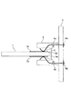
図1は子ボードの接続構造の説明図、図2はカードエッジ及びカードコネクタの規格の説明図である。
<Circuit board>
FIG. 1 is an explanatory diagram of a connection structure of a slave board, and FIG. 2 is an explanatory diagram of card edge and card connector standards.
図1に示すように、フルカラー複写機の制御部に搭載されたマザーボード5には、複数の子ボード(回路基板)1が装着されて、高い汎用性と広い拡張性とを実現している。マザーボード5にはISAバスやPCIバスと呼ばれる平行配線の高速バス5bが形成され、マザーボード5の高速バス5bは、カードコネクタ4からカードエッジ2を通じて子ボード1の高速バスに接続されている。マザーボード5には各種ソフト処理を行うプロセッサやメモリが実装され、子ボード1(回路基板)には、画像処理等の拡張機能用プロセッサや、通信回路等の拡張インターフェース機能が実装されている。カードエッジ2とカードコネクタ4との間で接続される電極数は、最大184極までの範囲で、用途・機能に応じて選択される。
As shown in FIG. 1, a plurality of child boards (circuit boards) 1 are mounted on a mother board 5 mounted on a control unit of a full-color copying machine, thereby realizing high versatility and wide expandability. A high-
図2に示すように、マザーボード5にカードコネクタ4を実装して、用途・機能に応じた子ボード1のみが組み込まれ、子ボード1のカードエッジ(基板の端部)2を介して電気的な接続を行う。カードコネクタ4に、子ボード1のカードエッジ2が挿入されることで、コンタクト電極4a、4bがカードエッジ2のカードエッジ電極2a、2bに接触してマザーボード5の回路パターン6a、6bと子ボード1とが電気的に接続される。これらの電極は、基板の端部近傍に設けられている。
As shown in FIG. 2, a
カードコネクタ(プリント基板コネクタ)4のコンタクト電極4a、4bの配置、仕様等は、電子部品の標準化を推進する業界団体で標準化され、これらの指針に基づいて、接触子が設定されている。カードエッジ2に沿って多数配置されたカードエッジ電極2a、2bの配置、仕様等も、同じ業界団体で標準化され、これらの指針に基づいて、カードコネクタ4のメーカから推奨の電極パターンが提示されている。業界団体としては、JEDEC(Joint Electron Device Engineering Council)、PCI−SIG等がある。
The arrangement and specifications of the
ここでは、例えば、カードエッジ2の長さL1=10mm、厚さt1=1.6mm、カードエッジ電極2a、2bのピッチ2.54mm、幅1.6mm、テーパ角度θ=30〜45度、テーパ深さtm=0.5mmのように規格が定められている。
Here, for example, the length L1 of the
また、カードエッジ2が突き当たる挿入深さL3=7.62mm、コンタクト電極4a、4bの接触位置からカードエッジ2の突き当たり位置までの距離L2=3.62mm、カードコネクタ4の高さL4=15.49mmのように規格が定められている。
Further, the insertion depth L3 at which the
<比較例>
図3は比較例の子ボードの装着状態の説明図、図4は比較例のカードエッジの斜視図である。
<Comparative example>
FIG. 3 is an explanatory view of the mounting state of the child board of the comparative example, and FIG. 4 is a perspective view of the card edge of the comparative example.
図3に示すように、比較例の子ボード1Hは、カードエッジ2の先端がカードスロット4eの底に突き当たるまで挿入される。電気的な接合は、子ボード1の表裏表面のカードエッジ電極2a、2bに対して、カードコネクタ4のコンタクト電極4a、4bが接触して行われる。
As shown in FIG. 3, the
コンタクト電極4a、4bは、それぞれバネ性を有し、カードエッジ2をカードスロット4eに挿入する過程で、カードエッジ2がコンタクト電極4a、4bの間隔を押し広げる。そして、カードエッジ2の挿入抵抗を軽減して子ボード1の挿入が容易になるように、コンタクト電極4a、4bのバネ力は弱く設定されているので、コンタクト電極4a、4bがカードエッジ電極2a、2bを押す接触圧は低い。
Each of the
図4に示すように、コンタクト電極4aの接触圧が低いため、カードエッジ2のテーパ面2pで付着した異物Dをカードエッジ電極2aの表面で摺擦除去する機能を期待できない。この結果、コンタクト電極4aに付着したままカードエッジ電極2a上を引き摺られた異物Dがコンタクト電極4aとカードエッジ電極2aとの接触を妨げて、接触不良が発生する。
As shown in FIG. 4, since the contact pressure of the
すなわち、カードコネクタ4は、コンタクト電極4a、4bがたくさんあるため、1つ当たりの接続信頼性が一定だとしても、少ない場合に比較してトータルの接続信頼性が低くなる。これに加えて、コンタクト電極4a、4bの接触圧が低いため、比較例1の子ボード1Hは、カードエッジ電極2a、2bとコンタクト電極4a、4bとの接続信頼性が相当に低い。
That is, since the
特に、ガラスエポキシ材料は、ガラス繊維の織布にエポキシ樹脂を含浸固化しているため、繊維束に直角なテーパ面の切断面に繊維端が密集して突出し、大量のエポキシ粉を拘束している。このため、コンタクト電極4aがテーパ面をこすり上げると、拘束されたエポキシ粉や繊維屑が押し出されてカードエッジ電極2aに引き摺り上げられる。
In particular, glass epoxy materials are made by impregnating and solidifying a glass fiber woven fabric with an epoxy resin, so that the fiber ends protrude densely on the cut surface of the taper surface perpendicular to the fiber bundle and restrain a large amount of epoxy powder. Yes. For this reason, when the
このため、従来は、コンタクト電極4a、4bの接触不良を無くすために、カードエッジ2のアルコール清掃や準クリーンルームでの組み立て作業などを通して、異物Dがカードエッジ2に付着しないようにしている。しかし、大きな繊維屑等の排除はできても、樹脂粉等の微小粒子の異物Dはできず、コンタクト電極4a、4bの接触不良を十分に低減することができない。
For this reason, conventionally, in order to eliminate contact failure between the
<実施例1>
図5は実施例1の子ボードのカードエッジの説明図、図6は実施例1の子ボードをカードコネクタに挿入した状態の説明図、図7は実施例1の子ボードの装着状態の説明図、図8は実施例1のカードエッジの斜視図、図9はカードエッジの挿入過程の説明図である。図5中、(a)は平面図、(b)は側断面図である。図6はカードエッジの側断面図、図7は凹部の形成方法の説明図である。
<Example 1>
5 is an explanatory diagram of the card edge of the slave board of the first embodiment, FIG. 6 is an explanatory diagram of a state in which the slave board of the first embodiment is inserted into the card connector, and FIG. 7 is an explanatory diagram of the mounted state of the slave board of the first embodiment. FIG. 8 is a perspective view of the card edge according to the first embodiment, and FIG. 9 is an explanatory diagram of the card edge insertion process. 5A is a plan view and FIG. 5B is a side sectional view. FIG. 6 is a side sectional view of the card edge, and FIG.
図5の(a)に示すように、実施例1では、カードエッジ2に配置されたカードエッジ電極2aにおけるコンタクト電極4bの停止位置とカードエッジ2の先端との間に長方形の凹部20を形成した。凹部20は、コンタクト電極4bの摺擦経路を横断して挿入方向に対向する起立面21を有する。なお、裏面側に配置されたカードエッジ電極(2b:図7)にも同様に凹部20が形成されている。
As shown in FIG. 5A, in the first embodiment, a
カードエッジ電極2aの先端に連続したメッキ電極35は、メッキ電極36と連続して、カードエッジ電極2aの表面に金メッキを電解メッキ処理した際の導線部分の残りである。電解メッキ処理後、カードエッジ2のテーパ面2pを切削加工する際に、メッキ電極36はプリント基板材料とともに除去されている。
The plating
図5の(b)に示すように、絶縁層上に銅板を貼付した基板材料をエッチングして、カードエッジ電極2a、メッキ電極35、メッキ電極36、子ボード(1:図1)の必要な回路パターンが同時に形成される。このとき、カードエッジ電極2aを覆ったレジスト層に凹部20に対応する開口を形成しておくことで、凹部20を設けたカードエッジ電極2aが形成される。カードエッジ電極2aの厚みは、(ベース)銅+(下地)ニッケルメッキ+(表面)金メッキを含んで47μm程度である。
As shown in FIG. 5B, the substrate material having a copper plate affixed on the insulating layer is etched, and the
このため、起立面21に対向する起立面22は、カードエッジ電極2aと同一に形成される。そして、凹部20の底面は、基板材料の絶縁層が露出しており、凹部20の深さは基板材料の絶縁層上に配置されたカードエッジ電極2aの厚みに等しい。
For this reason, the standing
図5の(a)に示すように、カードエッジ2の挿入方向に直角な凹部20の幅L7は、コンタクト電極4aの摺擦幅よりも長い。カードエッジ2の挿入方向に沿った凹部20の長さL6は、カードエッジ2のテーパ面2pで発生する異物の最大長さよりも長い。凹部20の深さは、カードエッジ2のテーパ面2pで発生する異物の最大厚みの1/2よりも深い。起立面21は、カードエッジ2のテーパ面2pよりも挿入方向に対する傾き角度が大きい。
As shown in FIG. 5A, the width L7 of the
図5の(b)に示すように、実施例1の子ボード1は、エッチングによる回路パターンの形成後、カードエッジ電極2aに厚さ2μmの金メッキを電解メッキ処理により形成している。
子ボード1の材料:厚さ45μmの銅板を貼付したガラスエポキシ基板
子ボード1の厚さ:1.6mm
テーパ面2pの傾き:基板面に対して表裏30度
カードエッジ電極2aの材質:(ベース)銅+(下地)ニッケルメッキ+(表面)金メッキ
カードエッジ電極2aの幅:1mm
カードエッジ電極2aの長さ:4.4mm
カードエッジ電極2aの厚み:47μm
カードエッジ電極2aの間隔:0.27mm
メッキ電極35の幅:0.2mm〜0.6mm
コンタクト電極4aの幅:0.4mm
凹部20の長さL6:0.2mm
凹部20の幅L7:0.6mm
凹部20の深さ:47μm
カードエッジ20の先端から凹部20までの長さL8:1.6mm
As shown in FIG. 5B, in the
Sub-board 1 material: Glass epoxy board with a 45 μm thick copper plate pasted Thickness of sub-board 1: 1.6 mm
Inclination of
Spacing between
The width of the plating electrode 35: 0.2 mm to 0.6 mm
Depth 20: 47 μm
Length L8 from the tip of the
図6に示すように、子ボード1は、カードエッジ2の先端がカードスロット4eに突き当たるまで、カードコネクタ4に挿入される。カードエッジ2の先端がカードスロット4eに突き当たった状態が子ボード1の装着状態であって、マザーボード5上の電子回路と子ボード1上の電子回路とが電気的に接続されて機能する状態である。
As shown in FIG. 6, the
図7に示すように、カードコネクタ4に対するカードエッジ2の嵌合状態が達成される。子ボード1は、コンタクト電極4a、4bに挟まれて嵌合する。このとき、コンタクト電極4a、4bは、凹部20を越えた位置へ達して、カードエッジ電極2a、2bにそれぞれ接触導通している。
As shown in FIG. 7, the fitting state of the
図8に示すように、コンタクト電極4a、4bがテーパ面2pをカードエッジ電極2a、2bに向かってこすり上げる過程で異物Dが発生する。異物Dは、コンタクト電極4a、4bに引き摺られて、破線で示すコンタクト電極4a、4bの摺擦経路を移動し続けると、コンタクト電極4a、4bとカードエッジ電極2a、2bとの間に挟み込まれて接触不良を発生する。テーパ面2pに存在した異物Dがカードエッジ電極2aの表面を引き摺られる過程で、凹部20のエッジで掻き取るように除去される。
As shown in FIG. 8, foreign matter D is generated in the process in which the
図9の(a)に示すように、子ボード1をカードコネクタ4に挿入すると、コンタクト電極4a、4bがテーパ面2pに突き当たって、テーパ面2pをカードエッジ電極2a、2bに向かってこすり上げる。このとき、テーパ面2pに露出したガラス繊維の隙間から大量のエポキシ粉が排出される。テーパ面2pの切削加工で発生したガラス繊維の切れ端やガラス粉もコンタクト電極4a、4bによってテーパ面2pからこすり出される。
As shown in FIG. 9A, when the
図9の(b)に示すように、更に子ボード1を挿入することにより、テーパ面2pで発生してコンタクト電極4aに付着した異物Dに対して、カードエッジ電極2aの先端のメッキ電極35の段差が、1回目の掻き取り除去を行う。しかし、メッキ電極35の段差は、テーパ面2pと同じ傾きで起立しているため、異物Dの多くは、そのままコンタクト電極2aに乗り上げてコンタクト電極2aの表面を引き摺られる。メッキ電極35の幅は、コンタクト電極4a、4bの幅よりも狭いため、メッキ電極35の両側にはみ出した部分に対しても掻き取り機能を発揮できない。
As shown in FIG. 9B, by inserting the
図9の(c)に示すように、更に子ボード1を挿入することにより、カードエッジ電極2a、2bに配置した凹部20の段差が、2回目の掻き取り除去を行う。凹部20の段差は、カードエッジ電極2a、2bの表面から垂直に立ち下がっており、想定する最大の異物Dの厚みより大きい47μmの高さがある。コンタクト電極4a、4bに引き摺られる異物Dは、凹部20に落ち込み、凹部20の起立面のエッジが異物Dを剥がすようにコンタクト電極4a、4bを摺擦する過程で、コンタクト電極4a、4bから分離される。異物Dは、カードコネクタ4にカードエッジ2が嵌合するにしたがって凹部20で除去される。
As shown in FIG. 9 (c), when the
図9の(d)に示すように、子ボード1を最後まで挿入することにより、通常使用される位置まで子ボード1のカードエッジ2がカードコネクタ4に挿入嵌合される。異物Dを分離されたコンタクト電極4a、4bは、カードエッジ電極2a、2bの所定位置に達して電気的な接続を達成する。このように、カードエッジ電極2a、2bに凹部20を設けたことにより、比較例に比べて、更なる異物排除機能が働き、より完全な接触性を実現できた。
As shown in FIG. 9D, by inserting the
図7に示すように、実施例1では、凹部20をカードエッジ電極2a、2bのエッチングにより形成したので、凹部20を形成するための追加工程が不要である。電極材料を溶かすエッチング処理で凹部20を形成するので、穿孔することなく、容易にかつ経済的に異物排除機能を実現できる。電極材料を析出させるメッキ処理で凹部20の縁を覆うことにより、穿孔することなく、容易にかつ経済的に異物排除機能を実現できる。
As shown in FIG. 7, in Example 1, since the recessed
実施例1では、凹部20の深さを想定する最大厚さの異物の1/2以上としたため、起立面21を乗り越えて凹部20から異物が転がり出すことができない。最大厚さの異物の厚みは20μmであるが、80μm程度の大きなものでも起立面21でせき止めて除去可能である。
In Example 1, since the depth of the
厚さ45μのカードエッジ電極2aをエッチングして凹部20を構成したため、凹部20の深さは、想定する20μmの最大異物より大きい45μmとなっている。凹部20の深さを想定する最大の異物の厚みよりも大きくすることで、異物の厚みに邪魔されることなく、起立面21と電極面のエッジがコンタクト電極4a、4bの表面を摺擦させ得る。これにより、起立面21と電極面のエッジがコンタクト電極4a、4bの表面から異物を切り分けるように進行して、効率的な異物除去が達成される。
Since the
さらに、凹部20の長さL6を想定する20μmの最大異物よりも長い0.2mmとしたので、凹部20に最大異物を落とし込んで、コンタクト電極4aの表面が起立面21とカードエッジ電極2aの表面とのエッジに摺擦する。
Further, since the length L6 of the
起立面21とカードエッジ電極2aの表面とのエッジが、コンタクト電極4aと異物の界面をせん断するように切り分けるので、粘着状態の異物、液体、表面で凝固した物質等でもコンタクト電極4aから分離される。想定する最大異物よりもはるかに大きな200μmの異物でも同様に効率的に除去できる。
Since the edge between the rising
さらに、凹部20の幅L7をコンタクト電極4aの幅0.4mmよりも大きな0.6mmとしたため、コンタクト電極4aのどこに付着した異物でも漏らすことなく起立面21にて掻き落とすことができる。
Furthermore, since the width L7 of the
実施例1によれば、カードエッジ電極2a、2b上のコンタクト電極4a、4bの停止位置から離れた位置に凹部20を設けたので、凹部20に影響されない従来どおりのカードエッジ電極2a、2bとコンタクト電極4a、4bとの電気接続が達成される。そして、コンタクト電極4a、4bに付着した異物を凹部20に取り込んで保持できるため、カードエッジ電極2a、2bとコンタクト電極4a、4bとの間に異物を挟み込んで接触不良となる頻度が大幅に低下し、従来にはない高い信頼性を実現できた。
According to the first embodiment, since the
さらに、該平面電極先端部分の電極材料を溶かすエッチング手段で凹部を形成することで安価、且つ大量にプリント基板コネクタを供給することが可能となった。 Furthermore, it has become possible to supply a large number of printed circuit board connectors at low cost by forming the recesses with an etching means that dissolves the electrode material at the tip of the planar electrode.
<実施例2>
図10は実施例2の子ボードのカードエッジの説明図である。実施例2は、カードエッジ電極2aの先端と、破線で示すコンタクト電極4aの停止位置との間に2つの凹部20A、20Bを形成している。それ以外の構成及び機能は実施例1と同一であるので、共通する構成には図5と共通の符号を付して重複する説明を省略する。
<Example 2>
FIG. 10 is an explanatory diagram of the card edge of the slave board according to the second embodiment. In the second embodiment, two
カードエッジ2を挿入することにより、テーパ面2pで発生してコンタクト電極4aに付着した異物Dに対して、メッキ電極35の先端の段差が、1回目の掻き取り除去を行う。
By inserting the
カードエッジ2を更に挿入することにより、カードエッジ電極2aに配置した凹部20Aの起立面21Aが、2回目の掻き取り除去を行う。
By further inserting the
カードエッジ2を更に挿入することにより、カードエッジ電極2aに配置した凹部20Bの起立面21Bが、3回目の掻き取り除去を行う。凹部20Bの段差は、カードエッジ電極2aの表面から垂直に立ち下がっており、想定する最大の異物Dの厚みより大きい47μmの高さがある。コンタクト電極4aに引き摺られる異物Dは、凹部20に落ち込み、凹部20Bの起立面21Bのエッジが異物Dを剥がすようにコンタクト電極4a、4bを摺擦する過程で、コンタクト電極4a、4bから分離される。
By further inserting the
実施例2では、実施例1よりも掻き取り回数が1回多いため、更なる異物排除機能が働き、カードエッジ電極2a、2bに対するコンタクト電極4a、4bのより完全な接触性を実現できる。カードエッジ電極2aに凹部20A、20Bを複数設けたことにより、より高い接続信頼性を確保できた。
In the second embodiment, since the number of scrapes is one more than that in the first embodiment, a further foreign substance removing function works, and a more complete contact of the
<実施例3>
図11は実施例3の子ボードのカードエッジの説明図である。実施例3は、カードエッジ電極2aを先端側へ拡張して凹部20Cを形成している。それ以外の構成及び機能は実施例1と同一であるので、共通する構成には図5と共通の符号を付して重複する説明を省略する。
<Example 3>
FIG. 11 is an explanatory diagram of the card edge of the slave board according to the third embodiment. In Example 3, the
実施例3の子ボードは、電子部品の標準化を推進する業界団体であるJEDEC(Joint Electron Device Engineering Council)で標準化されている。この指針に基づいて、プリント基板コネクタのメーカ(ヒロセ電機株式会社)から推奨のカードエッジの仕様、電極配置等が提示されている。 The child board of Example 3 is standardized by JEDEC (Joint Electron Engineering Engineering Council), which is an industry group that promotes standardization of electronic components. Based on this guideline, a recommended card edge specification, electrode arrangement, etc. are presented by a manufacturer of printed circuit board connectors (Hirose Electric Co., Ltd.).
図11に示すように、プリント基板コネクタのメーカから推奨されたカードエッジ電極2aの位置(図5の(a)参照)からカードエッジ2側へ電極領域を拡張して、拡張した電極領域に凹部20Cを形成した。凹部20Cの大きさ、深さ、製造方法等は実施例1と同様である。
As shown in FIG. 11, the electrode area is extended from the position of the
実施例3では、メーカから推奨された電極領域を損なうことなく、凹部20Cを形成しているので、推奨の接触領域と、推奨の標準化機能を確保しながら、2回目の異物排除機能を実現できる。 In the third embodiment, since the recess 20C is formed without damaging the electrode area recommended by the manufacturer, the second foreign substance removal function can be realized while ensuring the recommended contact area and the recommended standardization function. .
同様に、メーカーから推奨されていないカードコネクタまたは、新規のカードコネクタでも、メーカ仕様で指定されたカードエッジ電極2aの外に凹部20Cを設けることで、メーカ仕様機能を完全に確保しながら、2回目の異物排除機能を実現できる。
Similarly, even with a card connector not recommended by the manufacturer or a new card connector, the concave portion 20C is provided outside the
実施例3によれば、凹部20Cを、標準化仕様・メーカ仕様で指定された電極領域外に設けることで、従来からの接触領域と、標準化・メーカ仕様の機能を確保することができた。 According to the third embodiment, by providing the recess 20C outside the electrode region specified by the standardization specification / manufacturer specification, the conventional contact region and the standardization / manufacturer specification function can be secured.
<実施例4>
図12は実施例4の子ボードのカードエッジの説明図である。図12中、(a)は平面図、(b)は側断面図である。実施例4は、実施例1における凹所20の幅L7がカードエッジ電極2aの幅以上の場合である。それ以外の構成及び実質的な機能は実施例1と同一であるので、共通する構成には図5と共通の符号を付して重複する説明を省略する。
<Example 4>
FIG. 12 is an explanatory diagram of the card edge of the slave board according to the fourth embodiment. In FIG. 12, (a) is a plan view and (b) is a side sectional view. Example 4 is a case where the width L7 of the
図12の(a)に示すように、カードエッジ電極2aの先端から距離L6離して、異物分離用のフロート電極2cを形成してある。カードエッジ電極2a及びフロート電極2cは、実施例1と同様なプリント基板材料を用いた同様なエッチング処理によって同時に形成される。なお、実施例4では、カードエッジ電極2a及びフロート電極2cにメッキ電極は設けず、無電解メッキ処理によって表面に金メッキを施した。
As shown in FIG. 12A, a float electrode 2c for separating foreign substances is formed at a distance L6 from the tip of the
実施例4では、カードエッジ電極2aとフロート電極2cとの間にカードエッジ電極2a面から見た凹部20Dが形成されている。そして、凹部20Dの起立面21Dを用いて、従来からの接触領域と、標準化機能を確保しながら、2回目の異物排除機能を実現できる。
In Example 4, a recess 20D as viewed from the
<実施例5>
図13は実施例5の積層基板の説明図である。実施例5は、カードエッジ電極をシート状の絶縁層に形成したシート基板層を有し、凹部の深さはシート基板層の厚みに等しい。
<Example 5>
FIG. 13 is an explanatory diagram of the multilayer substrate of Example 5. Example 5 has a sheet substrate layer in which a card edge electrode is formed in a sheet-like insulating layer, and the depth of the recess is equal to the thickness of the sheet substrate layer.
図13に示すように、実施例5の積層基板は、プリント基板1Aにフレキシブル基板1Bを貼付して組み立てられている。フレキシブル基板1Bは、柔軟性ある樹脂シート1fの表面に厚さ20μmの銅箔1gを貼付して形成されており、銅箔1gをエッチング処理してカードエッジ電極2aが形成されている。回路配線が形成されたプリント基板1Aに回路配線が形成されたフレキシブル基板1Bを積層することで、立体的な回路配線を行っており、プリント基板1Aの回路配線は、フレキシブル基板1Bに形成された不図示のスルーホールによって電気的に接続されている。
As shown in FIG. 13, the laminated substrate of Example 5 is assembled by attaching a
フレキシブル基板1Bは、カードエッジ電極2aを含む回路パターンをエッチング処理により形成した後に、凹所20Eを打ち抜いて、樹脂シート1fの厚みに銅箔1gの厚みを加えた高さの起立面21Eを形成している。凹部20Eの段差は、カードエッジ電極2aの表面から垂直に立ち下がって異物を落とし込み、コンタクト電極4aから分離させる。
After forming a circuit pattern including the
実施例5では、柔軟性ある絶縁性の樹脂シートにも凹部形成を適用することで、より高い段差を形成して接続信頼性を確保できた。 In Example 5, the formation of a recess was also applied to a flexible insulating resin sheet, thereby forming a higher step and ensuring connection reliability.
1 子ボード
2 カードエッジ
2a、2b カードエッジ電極
2p テーパ面
4 カードコネクタ
4a、4b コンタクト電極
4e カードスロット
5 マザーボード
20、20A、20B、20C、20D、20E 凹部
21、21A、21B、21C、21D、21E 起立面
D 異物
1
Claims (3)
前記基板の前記コネクタへの挿入に伴う前記コンタクト電極の停止位置と前記基板の端部との間に、前記電極の電極面よりも低く形成された凹部を備え、
前記凹部は、前記電極と同時にエッチングにより形成され、
前記凹部の深さは、前記基板の絶縁層上に配置された前記電極の厚みに等しく、最大異物の厚みの1/2以上であって、
前記基板の挿入方向における前記凹部の長さは、前記最大異物の長さよりも長いことを特徴とする回路基板。 An electrode is provided in the vicinity of the end of the substrate, and the end provided with the electrode is inserted into the connector so that the electrode comes into contact with the contact electrode provided on the connector to be electrically connected. In the circuit board,
Between the stop position of the contact electrode accompanying the insertion of the substrate into the connector and the end of the substrate, a recess formed lower than the electrode surface of the electrode ,
The recess is formed by etching simultaneously with the electrode,
The depth of the recess is equal to the thickness of the electrode disposed on the insulating layer of the substrate, and is 1/2 or more of the thickness of the maximum foreign matter,
The circuit board according to claim 1, wherein a length of the recess in the insertion direction of the board is longer than a length of the maximum foreign matter .
基板の挿入方向に直角な方向の前記凹部の幅は、前記コンタクト電極の摺擦幅よりも長く、
基板の挿入方向とは反対方向に向いた前記凹部の起立面は、前記テーパ面よりも基板の挿入方向に対する傾き角度が大きいことを特徴とする請求項1記載の回路基板。 A tapered surface at an end of the substrate;
The width of the recess in the direction perpendicular to the substrate insertion direction is longer than the rubbing width of the contact electrode,
Rising surface of the recess facing the opposite direction to the insertion direction of the substrate, the circuit board according to claim 1, wherein the large inclination angle with respect to the insertion direction of the substrate than the tapered surface.
前記最大異物の厚みは20μmであることを特徴とする請求項1又は2に記載の回路基板。The circuit board according to claim 1, wherein a thickness of the maximum foreign matter is 20 μm.
Priority Applications (1)
| Application Number | Priority Date | Filing Date | Title |
|---|---|---|---|
| JP2008171067A JP5253016B2 (en) | 2008-06-30 | 2008-06-30 | Circuit board |
Applications Claiming Priority (1)
| Application Number | Priority Date | Filing Date | Title |
|---|---|---|---|
| JP2008171067A JP5253016B2 (en) | 2008-06-30 | 2008-06-30 | Circuit board |
Publications (3)
| Publication Number | Publication Date |
|---|---|
| JP2010010600A JP2010010600A (en) | 2010-01-14 |
| JP2010010600A5 JP2010010600A5 (en) | 2011-08-25 |
| JP5253016B2 true JP5253016B2 (en) | 2013-07-31 |
Family
ID=41590695
Family Applications (1)
| Application Number | Title | Priority Date | Filing Date |
|---|---|---|---|
| JP2008171067A Expired - Fee Related JP5253016B2 (en) | 2008-06-30 | 2008-06-30 | Circuit board |
Country Status (1)
| Country | Link |
|---|---|
| JP (1) | JP5253016B2 (en) |
Cited By (2)
| Publication number | Priority date | Publication date | Assignee | Title |
|---|---|---|---|---|
| CN104701657A (en) * | 2013-11-01 | 2015-06-10 | 森萨塔科技麻省公司 | Connector |
| US10517186B2 (en) | 2017-08-23 | 2019-12-24 | Sensata Technologies, Inc. | Socket |
Families Citing this family (3)
| Publication number | Priority date | Publication date | Assignee | Title |
|---|---|---|---|---|
| KR101719699B1 (en) * | 2010-10-05 | 2017-03-27 | 삼성전자주식회사 | Memory module and method of manufacturing the memory module |
| CN108075276B (en) * | 2016-11-11 | 2020-01-07 | 泰科电子(上海)有限公司 | Connector and connector assembly |
| JP2023069689A (en) * | 2021-11-08 | 2023-05-18 | 日本端子株式会社 | Card edge type printed wiring board |
Family Cites Families (4)
| Publication number | Priority date | Publication date | Assignee | Title |
|---|---|---|---|---|
| JPH07302975A (en) * | 1994-03-09 | 1995-11-14 | Yazaki Corp | Treatment method of terminal of circuit board |
| JP3904321B2 (en) * | 1998-03-13 | 2007-04-11 | タイコエレクトロニクスアンプ株式会社 | Printed board |
| JP2000113920A (en) * | 1998-10-01 | 2000-04-21 | Mitsubishi Electric Corp | Module |
| JP2007266618A (en) * | 2001-07-30 | 2007-10-11 | Seiko Epson Corp | Circuit substrate, ink cartridge using same, connection device therefor, and ink-jet type recorder using same |
-
2008
- 2008-06-30 JP JP2008171067A patent/JP5253016B2/en not_active Expired - Fee Related
Cited By (3)
| Publication number | Priority date | Publication date | Assignee | Title |
|---|---|---|---|---|
| CN104701657A (en) * | 2013-11-01 | 2015-06-10 | 森萨塔科技麻省公司 | Connector |
| CN104701657B (en) * | 2013-11-01 | 2019-01-01 | 森萨塔科技公司 | Connector |
| US10517186B2 (en) | 2017-08-23 | 2019-12-24 | Sensata Technologies, Inc. | Socket |
Also Published As
| Publication number | Publication date |
|---|---|
| JP2010010600A (en) | 2010-01-14 |
Similar Documents
| Publication | Publication Date | Title |
|---|---|---|
| JP5253016B2 (en) | Circuit board | |
| US20070199194A1 (en) | Method of electroplating a plurality of conductive fingers | |
| US7285729B2 (en) | Printed circuit board | |
| JP2004335548A (en) | Connection structure of multilayer printed wiring board | |
| EP2529605B1 (en) | Contact piece of golden finger, golden finger and connector comprising the golden finger | |
| JP5600428B2 (en) | Female connector block and connector | |
| EP2077702A2 (en) | Wiring board and manufacturing method thereof and wiring board assembly | |
| WO2008094390A1 (en) | Disk drive interposer | |
| TW201526729A (en) | Printed wiring board and connector connected to said wiring board | |
| US20100134995A1 (en) | Electrical Interconnection System | |
| JP5110346B2 (en) | Substrate and substrate manufacturing method | |
| JP5142386B2 (en) | connector | |
| KR20070084174A (en) | Two piece mid-plane | |
| CN101002366A (en) | Design and method for plating PCI express (PCIE) edge connector | |
| JP2008192993A (en) | Method of manufacturing printed board | |
| JP2007273655A (en) | Flexible flat circuit board and manufacturing method therefor | |
| JP2007317981A (en) | Flexible printed wiring board, and backlighting device of liquid crystal module | |
| JPS599993A (en) | Method of connecting electric circuit of printed board | |
| JP7247557B2 (en) | CIRCUIT BOARD, CIRCUIT BOARD MANUFACTURING METHOD, IMAGING DEVICE | |
| JP6597810B2 (en) | Mounting structure, structural component, and manufacturing method of mounting structure | |
| US20070202713A1 (en) | Connector Employing Flexible Printed Board | |
| JP2005056605A (en) | Connector, cable or wiring board joined to connector | |
| JP3463539B2 (en) | Flexible circuit board with anisotropic conductive adhesive and manufacturing method | |
| JPH10335020A (en) | Structure for connecting printed wiring board to connector | |
| CN214481805U (en) | Wiring structure |
Legal Events
| Date | Code | Title | Description |
|---|---|---|---|
| A521 | Written amendment |
Free format text: JAPANESE INTERMEDIATE CODE: A523 Effective date: 20110630 |
|
| A621 | Written request for application examination |
Free format text: JAPANESE INTERMEDIATE CODE: A621 Effective date: 20110630 |
|
| RD05 | Notification of revocation of power of attorney |
Free format text: JAPANESE INTERMEDIATE CODE: A7425 Effective date: 20120125 |
|
| RD03 | Notification of appointment of power of attorney |
Free format text: JAPANESE INTERMEDIATE CODE: A7423 Effective date: 20120203 |
|
| A977 | Report on retrieval |
Free format text: JAPANESE INTERMEDIATE CODE: A971007 Effective date: 20120816 |
|
| A131 | Notification of reasons for refusal |
Free format text: JAPANESE INTERMEDIATE CODE: A131 Effective date: 20120821 |
|
| A521 | Written amendment |
Free format text: JAPANESE INTERMEDIATE CODE: A523 Effective date: 20121022 |
|
| RD04 | Notification of resignation of power of attorney |
Free format text: JAPANESE INTERMEDIATE CODE: A7424 Effective date: 20130228 |
|
| TRDD | Decision of grant or rejection written | ||
| A01 | Written decision to grant a patent or to grant a registration (utility model) |
Free format text: JAPANESE INTERMEDIATE CODE: A01 Effective date: 20130319 |
|
| A61 | First payment of annual fees (during grant procedure) |
Free format text: JAPANESE INTERMEDIATE CODE: A61 Effective date: 20130416 |
|
| R151 | Written notification of patent or utility model registration |
Ref document number: 5253016 Country of ref document: JP Free format text: JAPANESE INTERMEDIATE CODE: R151 |
|
| FPAY | Renewal fee payment (event date is renewal date of database) |
Free format text: PAYMENT UNTIL: 20160426 Year of fee payment: 3 |
|
| LAPS | Cancellation because of no payment of annual fees |