JP5250170B2 - Hydrogen storage powder and its preparation process - Google Patents
Hydrogen storage powder and its preparation process Download PDFInfo
- Publication number
- JP5250170B2 JP5250170B2 JP2001587503A JP2001587503A JP5250170B2 JP 5250170 B2 JP5250170 B2 JP 5250170B2 JP 2001587503 A JP2001587503 A JP 2001587503A JP 2001587503 A JP2001587503 A JP 2001587503A JP 5250170 B2 JP5250170 B2 JP 5250170B2
- Authority
- JP
- Japan
- Prior art keywords
- hydrogen storage
- powder
- hydrogen
- reactor
- temperature
- Prior art date
- Legal status (The legal status is an assumption and is not a legal conclusion. Google has not performed a legal analysis and makes no representation as to the accuracy of the status listed.)
- Expired - Fee Related
Links
Images


Classifications
-
- H—ELECTRICITY
- H01—ELECTRIC ELEMENTS
- H01M—PROCESSES OR MEANS, e.g. BATTERIES, FOR THE DIRECT CONVERSION OF CHEMICAL ENERGY INTO ELECTRICAL ENERGY
- H01M4/00—Electrodes
- H01M4/02—Electrodes composed of, or comprising, active material
- H01M4/24—Electrodes for alkaline accumulators
- H01M4/242—Hydrogen storage electrodes
-
- B—PERFORMING OPERATIONS; TRANSPORTING
- B22—CASTING; POWDER METALLURGY
- B22F—WORKING METALLIC POWDER; MANUFACTURE OF ARTICLES FROM METALLIC POWDER; MAKING METALLIC POWDER; APPARATUS OR DEVICES SPECIALLY ADAPTED FOR METALLIC POWDER
- B22F1/00—Metallic powder; Treatment of metallic powder, e.g. to facilitate working or to improve properties
- B22F1/14—Treatment of metallic powder
- B22F1/145—Chemical treatment, e.g. passivation or decarburisation
-
- B—PERFORMING OPERATIONS; TRANSPORTING
- B22—CASTING; POWDER METALLURGY
- B22F—WORKING METALLIC POWDER; MANUFACTURE OF ARTICLES FROM METALLIC POWDER; MAKING METALLIC POWDER; APPARATUS OR DEVICES SPECIALLY ADAPTED FOR METALLIC POWDER
- B22F9/00—Making metallic powder or suspensions thereof
- B22F9/02—Making metallic powder or suspensions thereof using physical processes
- B22F9/023—Hydrogen absorption
-
- C—CHEMISTRY; METALLURGY
- C01—INORGANIC CHEMISTRY
- C01B—NON-METALLIC ELEMENTS; COMPOUNDS THEREOF; METALLOIDS OR COMPOUNDS THEREOF NOT COVERED BY SUBCLASS C01C
- C01B3/00—Hydrogen; Gaseous mixtures containing hydrogen; Separation of hydrogen from mixtures containing it; Purification of hydrogen
- C01B3/0005—Reversible uptake of hydrogen by an appropriate medium, i.e. based on physical or chemical sorption phenomena or on reversible chemical reactions, e.g. for hydrogen storage purposes ; Reversible gettering of hydrogen; Reversible uptake of hydrogen by electrodes
- C01B3/001—Reversible uptake of hydrogen by an appropriate medium, i.e. based on physical or chemical sorption phenomena or on reversible chemical reactions, e.g. for hydrogen storage purposes ; Reversible gettering of hydrogen; Reversible uptake of hydrogen by electrodes characterised by the uptaking medium; Treatment thereof
- C01B3/0031—Intermetallic compounds; Metal alloys; Treatment thereof
-
- C—CHEMISTRY; METALLURGY
- C01—INORGANIC CHEMISTRY
- C01B—NON-METALLIC ELEMENTS; COMPOUNDS THEREOF; METALLOIDS OR COMPOUNDS THEREOF NOT COVERED BY SUBCLASS C01C
- C01B3/00—Hydrogen; Gaseous mixtures containing hydrogen; Separation of hydrogen from mixtures containing it; Purification of hydrogen
- C01B3/0005—Reversible uptake of hydrogen by an appropriate medium, i.e. based on physical or chemical sorption phenomena or on reversible chemical reactions, e.g. for hydrogen storage purposes ; Reversible gettering of hydrogen; Reversible uptake of hydrogen by electrodes
- C01B3/001—Reversible uptake of hydrogen by an appropriate medium, i.e. based on physical or chemical sorption phenomena or on reversible chemical reactions, e.g. for hydrogen storage purposes ; Reversible gettering of hydrogen; Reversible uptake of hydrogen by electrodes characterised by the uptaking medium; Treatment thereof
- C01B3/0084—Solid storage mediums characterised by their shape, e.g. pellets, sintered shaped bodies, sheets, porous compacts, spongy metals, hollow particles, solids with cavities, layered solids
-
- H—ELECTRICITY
- H01—ELECTRIC ELEMENTS
- H01M—PROCESSES OR MEANS, e.g. BATTERIES, FOR THE DIRECT CONVERSION OF CHEMICAL ENERGY INTO ELECTRICAL ENERGY
- H01M4/00—Electrodes
- H01M4/02—Electrodes composed of, or comprising, active material
- H01M4/04—Processes of manufacture in general
-
- H—ELECTRICITY
- H01—ELECTRIC ELEMENTS
- H01M—PROCESSES OR MEANS, e.g. BATTERIES, FOR THE DIRECT CONVERSION OF CHEMICAL ENERGY INTO ELECTRICAL ENERGY
- H01M4/00—Electrodes
- H01M4/02—Electrodes composed of, or comprising, active material
- H01M4/36—Selection of substances as active materials, active masses, active liquids
- H01M4/38—Selection of substances as active materials, active masses, active liquids of elements or alloys
- H01M4/383—Hydrogen absorbing alloys
-
- B—PERFORMING OPERATIONS; TRANSPORTING
- B22—CASTING; POWDER METALLURGY
- B22F—WORKING METALLIC POWDER; MANUFACTURE OF ARTICLES FROM METALLIC POWDER; MAKING METALLIC POWDER; APPARATUS OR DEVICES SPECIALLY ADAPTED FOR METALLIC POWDER
- B22F2998/00—Supplementary information concerning processes or compositions relating to powder metallurgy
-
- Y—GENERAL TAGGING OF NEW TECHNOLOGICAL DEVELOPMENTS; GENERAL TAGGING OF CROSS-SECTIONAL TECHNOLOGIES SPANNING OVER SEVERAL SECTIONS OF THE IPC; TECHNICAL SUBJECTS COVERED BY FORMER USPC CROSS-REFERENCE ART COLLECTIONS [XRACs] AND DIGESTS
- Y02—TECHNOLOGIES OR APPLICATIONS FOR MITIGATION OR ADAPTATION AGAINST CLIMATE CHANGE
- Y02E—REDUCTION OF GREENHOUSE GAS [GHG] EMISSIONS, RELATED TO ENERGY GENERATION, TRANSMISSION OR DISTRIBUTION
- Y02E60/00—Enabling technologies; Technologies with a potential or indirect contribution to GHG emissions mitigation
- Y02E60/10—Energy storage using batteries
-
- Y—GENERAL TAGGING OF NEW TECHNOLOGICAL DEVELOPMENTS; GENERAL TAGGING OF CROSS-SECTIONAL TECHNOLOGIES SPANNING OVER SEVERAL SECTIONS OF THE IPC; TECHNICAL SUBJECTS COVERED BY FORMER USPC CROSS-REFERENCE ART COLLECTIONS [XRACs] AND DIGESTS
- Y02—TECHNOLOGIES OR APPLICATIONS FOR MITIGATION OR ADAPTATION AGAINST CLIMATE CHANGE
- Y02E—REDUCTION OF GREENHOUSE GAS [GHG] EMISSIONS, RELATED TO ENERGY GENERATION, TRANSMISSION OR DISTRIBUTION
- Y02E60/00—Enabling technologies; Technologies with a potential or indirect contribution to GHG emissions mitigation
- Y02E60/30—Hydrogen technology
- Y02E60/32—Hydrogen storage
-
- Y—GENERAL TAGGING OF NEW TECHNOLOGICAL DEVELOPMENTS; GENERAL TAGGING OF CROSS-SECTIONAL TECHNOLOGIES SPANNING OVER SEVERAL SECTIONS OF THE IPC; TECHNICAL SUBJECTS COVERED BY FORMER USPC CROSS-REFERENCE ART COLLECTIONS [XRACs] AND DIGESTS
- Y02—TECHNOLOGIES OR APPLICATIONS FOR MITIGATION OR ADAPTATION AGAINST CLIMATE CHANGE
- Y02P—CLIMATE CHANGE MITIGATION TECHNOLOGIES IN THE PRODUCTION OR PROCESSING OF GOODS
- Y02P20/00—Technologies relating to chemical industry
- Y02P20/10—Process efficiency
- Y02P20/129—Energy recovery, e.g. by cogeneration, H2recovery or pressure recovery turbines
Landscapes
- Chemical & Material Sciences (AREA)
- Chemical Kinetics & Catalysis (AREA)
- General Chemical & Material Sciences (AREA)
- Organic Chemistry (AREA)
- Electrochemistry (AREA)
- Engineering & Computer Science (AREA)
- Combustion & Propulsion (AREA)
- Inorganic Chemistry (AREA)
- Manufacturing & Machinery (AREA)
- Battery Electrode And Active Subsutance (AREA)
- Powder Metallurgy (AREA)
- Hydrogen, Water And Hydrids (AREA)
Description
(関連出願についての説明)
本発明は、1998年8月27日に出願された「A Method For Powder Of A Hydrogen Storage Alloy」と題する同時係属米国特許出願第09/141,668号、及び、1999年12日に出願された「Modified Electrochemical Hydrogen Storage Alloy Having Increased Capacity, Rate Capability and Catalytic Activity」と題する同時係属米国特許出願第09/290,633号(これらの同時係属出願の開示内容は、参照により本明細書に組み入れられる)の一部継続出願である。
(Description of related applications)
The present invention was filed on August 27, 1998, co-pending US patent application Ser. No. 09 / 141,668 entitled “A Method For Powder Of A Hydrogen Storage Alloy” and filed on Dec. 12, 1999. Co-pending US patent application Ser. No. 09 / 290,633, which is hereby incorporated by reference, the contents of co-pending U.S. patent application Ser. No. 09 / 290,633, entitled “Modified Electrochemical Hydrologic Storage Alloy, Having Increased Capacity, Rate Capability and Catalytic Activity”. Is a continuation-in-part application.
(発明の背景)
I.発明の分野
本発明は、水素貯蔵粉末、及び、それを製造するための方法に関するものである。より詳細には、本発明は、その粉末が燃えだすのを防ぎ、且つ、より容易な活性化をもたらすための加工表面酸化物を有する電気化学的な水素貯蔵粉末を製造するための方法に関するものである。
(Background of the Invention)
I. The present invention relates to a hydrogen storage powder and a method for producing the same. More particularly, the invention relates to a method for producing an electrochemical hydrogen storage powder having a processed surface oxide to prevent the powder from burning out and to provide easier activation. It is.
II.関連技術の説明
水素貯蔵材料は、バッテリーの電極材料、燃料電池、ゲッター、ヒートポンプ、及び水素ガスの貯蔵等を含む様々なテクノロジーにおいて用途が見出されている。水素貯蔵材料とは、水素をそれぞれ吸収も脱着もできる材料を意味している。幾つかの水素貯蔵材料の例は以下のものを含む:Mg、Ti、V、Nb、Pd、及びLa等の金属元素、並びに、TiFe、Mg2Ni、MgNi、ミッシュメタルをベースとしたAB5型、及びラーベス相をベースとしたAB2型等の幾つかの金属間合金。一般的に、水素貯蔵材料を製造するときには、大きな反応表面積が得られるという利点を得るため、水素貯蔵材料を多孔質下部構造の形態に形成する方法が執られている。多孔質下部構造は、典型的には、水素貯蔵材料を粉末化し、その粉末化された材料を適当な基材と共に複合体の形態に形成し、得られた複合体を1つもしくはそれ以上の前処理ステップ即ち「活性化」処理にかけることにより形成される。粉末化された材料の形成と、それに続く前処理は、この水素貯蔵材料の他の数ある特性の中でもとりわけ、表面積、活性部位、及び多孔度を高める効果がある。
II. 2. Description of Related Art Hydrogen storage materials have found use in a variety of technologies including battery electrode materials, fuel cells, getters, heat pumps, hydrogen gas storage, and the like. The hydrogen storage material means a material that can absorb and desorb hydrogen, respectively. Some examples of hydrogen storage materials include: metal elements such as Mg, Ti, V, Nb, Pd, and La, and AB 5 based on TiFe, Mg 2 Ni, MgNi, Misch metal And several intermetallic alloys such as AB 2 type based on Laves phase. In general, when producing a hydrogen storage material, a method of forming the hydrogen storage material in the form of a porous substructure has been carried out in order to obtain the advantage of obtaining a large reaction surface area. The porous substructure typically pulverizes the hydrogen storage material, forms the powdered material with a suitable substrate in the form of a composite, and converts the resulting composite into one or more composites. Formed by subjecting it to a pre-processing step or "activation" process. The formation of powdered material and subsequent pretreatment has the effect of increasing surface area, active site, and porosity, among other properties of this hydrogen storage material.
粉末化された水素貯蔵材料は、バッテリー電極の形成に特に有用である。粉末化された水素貯蔵材料を製造する方法及びその粉末材料からバッテリー電極を製造する方法は、一般的に既知であり、例えば米国特許第4,716,088号;第4,670,214号;第4,765,598号;第4,820,481号;及び第4,915,898号(これらの特許の開示内容は、参照により本明細書に組み入れられる)を含む数多くの特許に記載されている。金属水素化物バッテリー電極を製造する方法は、典型的には、微粉化された水素貯蔵材料を導電性基材に適用して固定するステップを含む。また、導電性基材への付着度を高め、且つ、バッテリーの性能を改善するため、この粉末に数多くの添加剤を加えることもできる。そのような添加剤は、結合剤や導電性充填剤を含み得る。
Powdered hydrogen storage materials are particularly useful for forming battery electrodes. Methods for producing powdered hydrogen storage materials and methods for producing battery electrodes from the powder materials are generally known, for example, U.S. Pat. Nos. 4,716,088; 4,670,214; No. 4,765,598; 4,820,481; and 4,915,898 (the disclosures of these patents are incorporated herein by reference). ing. A method of manufacturing a metal hydride battery electrode typically includes applying and securing a micronized hydrogen storage material to a conductive substrate. A number of additives can also be added to this powder in order to increase the degree of adhesion to the conductive substrate and to improve battery performance. Such additives can include binders and conductive fillers.
水素貯蔵材料は、数多くの方法で粉末化することができる。使用すべき特定の方法は、材料の組成、硬さ、表面酸化物を形成する性向、及び望まれる最終用途に依存する。既知の粉末化技法は、機械加工法、摩砕法、爆破法、造粒法、噴霧法、凝縮法、サイズ低減法、化学的沈殿法、または電着法を含めた機械的微粉化法及び化学的微粉化法、並びにそれらを組み合わせた方法を含む。また、摩耗法、剪断法、ボールミリング法、ハンマーミリング法、シュレッダー法、流体エネルギー法、及び摩擦円板法を含む他の通常用いられるサイズ低減法を付加的もしくは代替的に使用することもできる。有用な粒径分布または粒径分類を得るため、普通には、微粉化の後に篩い分けが行われる。微粉化を必ずしも必要としない他の技術は、噴射鋳造法及び気体噴霧法等の急速焼き入れ法を含む。
The hydrogen storage material can be pulverized in a number of ways. The particular method to be used depends on the material composition, hardness, propensity to form surface oxides, and the desired end use. Known pulverization techniques include mechanical pulverization and chemical methods, including machining, grinding, blasting, granulation, spraying, condensation, size reduction, chemical precipitation, or electrodeposition. Micronization method as well as a combination thereof. In addition, other commonly used size reduction methods including wear, shear, ball milling, hammer milling, shredder, fluid energy, and friction disk methods can be used additionally or alternatively. . To obtain a useful particle size distribution or particle size classification, sieving is usually performed after micronization. Other techniques that do not necessarily require pulverization include rapid quenching methods such as injection casting and gas spraying.
幾種類かの材料に対しては特定のサイズ低減技術がうまく機能するが、すべての材料に対してうまく機能する単一の技術はない。例えば、幾種類かの材料は、機械的破砕法のみを用いて破砕するのに充分な柔らかさを有している。また、幾種類かの材料に対しては、機械的微粉化法と化学的微粉化法の組み合わせが最も適している。また他の合金は、機械的に破砕するには硬すぎるため、化学的な方法で微粉化しなければならない。多くの機械的な粒径調整技術は、それ自体では、非常に硬い材料、特にロックウェル硬度が45より大きな材料を微粉化するのに有効でない。
Certain size reduction techniques work well for some materials, but no single technique works well for all materials. For example, some materials are soft enough to be crushed using only mechanical crushing methods. Also, for some types of materials, a combination of mechanical and chemical atomization methods is most suitable. Other alloys are too hard to be mechanically crushed and must be pulverized by chemical methods. Many mechanical particle size adjustment techniques are in themselves not effective for micronizing very hard materials, especially those with Rockwell hardness greater than 45.
バルク水素貯蔵材料は、通常は、種々の金属を一緒に溶融し、それらをボタンまたはインゴットの形態に鋳込むことにより形成される。バルク水素貯蔵材料は、組成的または構造的に規則的な状態であってもよいし、無秩序な状態であってもよく、あるいは、それらのどこか中間的な状態であってもよい。S.R.Ovshinsky、M.A.Fetcenko、及びJ.Rossによる「A Nickel Metal Hydride Battery for Electric Vehicles」(Science、Vol.260、1993年4月9日)で報じられているように:無秩序状態の電極材料における合金形成で利用できるようになった元素は、とりわけ、Li、C、Mg、Al、Si、Ca、Ti、V、Cr、Mn、Fe、Co、Ni、Cu、Y、Zr、Nb、Mo、Sn、La、W、及びReである。このリストは、金属原子1個当たりの貯蔵水素原子数を増大させることができる元素を含んでいる(Mg、Ti、V、Zr、Nb、及びLa)。その他の元素は、金属−水素結合強度の調節を可能にする(V、Mn、及びZr)か、あるいは、触媒特性をもたらして、充分な充電及び放電反応速度と気体の再結合を確実化し(Al、Mn、Co、Fe、及びNi);もしくは、酸化及び腐食抵抗性、改善された多孔度、及びイオン伝導度等の望ましい表面特性を付与することができる(Cr、Mo、及びW)。これらの合金にもたらされ得る広範囲の物理的特性により、MHバッテリーの性能を最適化することが可能になる。
Bulk hydrogen storage materials are usually formed by melting various metals together and casting them in the form of buttons or ingots. The bulk hydrogen storage material may be in a compositionally or structurally regular state, in a disordered state, or somewhere in between. S. R. Ovshinsky, M.M. A. Fetcenko, and J.M. As reported by Ross “A Nickel Metallic Battery for Electric Vehicles” (Science, Vol. 260, Apr. 9, 1993): Elements made available for alloy formation in disordered electrode materials Are, among others, Li, C, Mg, Al, Si, Ca, Ti, V, Cr, Mn, Fe, Co, Ni, Cu, Y, Zr, Nb, Mo, Sn, La, W, and Re. . This list includes elements that can increase the number of stored hydrogen atoms per metal atom (Mg, Ti, V, Zr, Nb, and La). Other elements allow adjustment of metal-hydrogen bond strength (V, Mn, and Zr) or provide catalytic properties to ensure sufficient charge and discharge kinetics and gas recombination ( Al, Mn, Co, Fe, and Ni); or can impart desirable surface properties such as oxidation and corrosion resistance, improved porosity, and ionic conductivity (Cr, Mo, and W). The wide range of physical properties that can be provided to these alloys allows the performance of MH batteries to be optimized.
規則度と無秩序度の間には広い領域があるということを利用して、上述の特性及び他の特性を改善すべく加工して水素貯蔵材料を作ることができる。この構造的及び組成的な規則度の値は、材料とプロセスの両者に依存することがあり得る。例えば、より高度に規則的な材料は、従来の溶融−鋳造法により形成され得る。ゆっくりとした冷却プロセスにより、化学的組成によっては、結晶成長と相当な構造上の規則的状態を作ることが出来る。逆に、高度に無秩序な材料は、通常は、溶融後に急速に焼き入れする高速冷却法により形成される。急速な冷却は、より高度に無秩序な材料をもたらすが、これも化学的な構成成分に依存する。
Utilizing the fact that there is a wide range between the degree of order and the degree of disorder, the hydrogen storage material can be made by processing to improve the above-mentioned properties and other properties. This structural and compositional order value can depend on both the material and the process. For example, more highly regular materials can be formed by conventional melt-casting methods. A slow cooling process can produce crystal growth and considerable structural regularity, depending on the chemical composition. Conversely, highly disordered materials are usually formed by a fast cooling method that rapidly quenches after melting. Rapid cooling results in a more highly disordered material, which also depends on the chemical constituents.
水素微粉化法を用いて水素貯蔵合金を微粉化する一つの成功する方法がOvonic Battery,Inc.で開発され、この方法は、1990年1月16にFetcenkoらに発行された「Hydride Reactor Apparatus for Hydrogen Comminution of Metal Hydride Hydrogen Storage Material」という名称の米国特許第4,893,756号(この特許の開示内容は、参照により本明細書に組み入れられる)に開示されている。継続的なたゆまぬ研究努力を通じ、Ovonic Battery,Inc.は、バッテリーの陰極において使用する硬い水素貯蔵材料を微粉化するための最初の水素貯蔵リアクターを開発した。この方法は、バッテリー電極を形成する上での特性が改善された新たな材料を開発する道を切り開いた。
One successful method of micronizing a hydrogen storage alloy using the hydrogen micronization method is described in Ovonic Battery, Inc. This method was developed in the United States Patent No. 75, entitled "Hydrogen Reactor Apparatus for Hydrology of Metal Hydrologic Storage Material 89," issued in January 16, 1990 to Fetcenko et al. The disclosure of which is incorporated herein by reference). Through continuous research efforts, Ovonic Battery, Inc. Has developed the first hydrogen storage reactor to micronize hard hydrogen storage materials for use in battery cathodes. This method paved the way for the development of new materials with improved properties in forming battery electrodes.
Fetcenkoらによれば、水素貯蔵粉末は、水素化物化/脱水素化物化サイクル処理による粉砕法により、金属インゴットまたは合金等のバルク材料から製造することができる。この水素化物化/脱水素化物化プロセスは、金属水素化物または水素貯蔵材料を、大きなインゴットまたはバルクのサイズから粒子の形態へサイズを低減する。上述の粉砕を果たすため、バルク材料が固定式の水素リアクターに入れられる。このリアクターは、真空下に置かれ、あらゆる残留空気を排除するため、アルゴンでパージされる。その後、圧力が少なくとも25psiになるまで、反応室に水素が戻し充填される。水素は、水素貯蔵材料に吸収され、これにより、金属格子の体積が膨張し、その水素貯蔵材料の粉砕がもたらされる。水素化には数時間を要することがあり、温度の上昇を招き得る。反応容器の温度を約100℃未満に維持するため、冷却が行われる。水素化後、水素貯蔵材料から水素を取り除くため、この粉砕された材料が脱水素化される。その後の段階で行われるバッテリー電極への形成に備え、酸素を含まない雰囲気下においてこの材料を包装することができる。
According to Fetcenko et al., Hydrogen storage powders can be produced from bulk materials such as metal ingots or alloys by a pulverization process by a hydride / dehydride cycle process. This hydride / dehydride process reduces the size of a metal hydride or hydrogen storage material from a large ingot or bulk size to a particulate form. To accomplish the above grinding, bulk material is placed in a stationary hydrogen reactor. The reactor is placed under vacuum and purged with argon to eliminate any residual air. The reaction chamber is then backfilled with hydrogen until the pressure is at least 25 psi. Hydrogen is absorbed into the hydrogen storage material, which causes the volume of the metal lattice to expand, resulting in comminution of the hydrogen storage material. Hydrogenation can take several hours and can lead to an increase in temperature. Cooling is performed to maintain the temperature of the reaction vessel below about 100 ° C. After hydrogenation, the ground material is dehydrogenated to remove hydrogen from the hydrogen storage material. This material can be packaged in an oxygen-free atmosphere in preparation for subsequent battery electrode formation.
Fetcenkoの特許及びそれの後継特許は、水素化ステップが圧力制御下で行われる水素微粉化法を教示している。残念ながら、圧力制御下における反応は、水素貯蔵材料の過剰な加熱をもたらし得る。過剰な加熱は、水素貯蔵材料の組成的及び構造的な規則性または無秩序性に予測不能な変化をもたらし得るため、望ましくない。更に、過剰な加熱は、長い冷却時間を必要とし、製造に要する時間の延長を招く。
The Fetcenko patent and its successor teach a hydrogen atomization process in which the hydrogenation step is performed under pressure control. Unfortunately, the reaction under pressure control can result in excessive heating of the hydrogen storage material. Excessive heating is undesirable because it can lead to unpredictable changes in the compositional and structural regularity or disorder of the hydrogen storage material. Furthermore, excessive heating requires a long cooling time and causes an increase in the time required for production.
水素貯蔵材料を空気に晒すと、それらの粒子の相当な部分に予測不能で一定しない酸化物形成が起こり得る。水素貯蔵材料の無制御な酸化または不均等な酸化は、通常その材料の表面に、好ましくないほどの厚さと密度と不均一性を持つ酸化物形成をもたらして活性化を困難にする。結果として生じるこのような表面状態のため、その表面は、バッテリー用の陰極材料としてそのままでは使用できなくなる。例えば、厚い酸化物層は、それが絶縁障壁として作用することにより、電極の初期活性化を遅らせる。絶縁障壁は、金属表面/電解質界面で起こる電気化学的反応速度及び電気化学的輸送プロセスを妨害し得る。それ故、酸素を含まない雰囲気下でそのような粉末を包装する方法等、酸化物形成を僅かしか伴わないか、あるいは酸化物形成を全く伴わずに水素貯蔵粉末を生成するための製造技術が使用されてきた。しかし、酸化物表面層を伴わない場合、La、Ce、Ti、V、Zr、Al等の金属と酸素との反応生成熱が高いため、そのような水素貯蔵材料は極めて自然発火性が高くなる。発火性粉末は、空気に晒されると激しく反応することがある。従って、発火性材料は、安全な作業条件が必須である大規模製造プラントに重大な火災の危険性をもたらす。 水素貯蔵材料の表面における酸化物形成に関わる上述の問題の幾つかを克服するために数多くの方法が導入されてきた。これらの方法は、殆ど例外なく、前処理ステップ即ち「活性化」を用いることによる粉末形成後に焦点を当てている。本明細書では、活性化という用語は、粉末形成後に電気化学的水素貯蔵材料の水素移動速度を改善するために使用される処理方法のみを特に指している。例えば、1987年12月29日にReichmanらに発行された米国特許第4,716,088号を参照すると、そこには、再充電式の水素貯蔵陰極を活性化するための方法が教示されている(この特許の開示内容は、参照により本明細書に組み入れられる)。
Exposure of the hydrogen storage material to air can result in unpredictable and inconsistent oxide formation in a significant portion of the particles. Uncontrolled or uneven oxidation of the hydrogen storage material usually results in oxide formation on the surface of the material with undesirable thickness, density and non-uniformity, making activation difficult. Because of the resulting surface condition, the surface cannot be used as it is as a cathode material for a battery. For example, a thick oxide layer delays the initial activation of the electrode by acting as an insulating barrier. Insulating barriers can interfere with the electrochemical kinetics and electrochemical transport processes that occur at the metal surface / electrolyte interface. Therefore, there is a manufacturing technique for producing hydrogen storage powder with little or no oxide formation, such as a method of packaging such powder in an oxygen-free atmosphere. Have been used. However, in the absence of an oxide surface layer, the reaction product heat of metals such as La, Ce, Ti, V, Zr, and Al and oxygen is high, and such a hydrogen storage material is extremely pyrophoric. . Ignitable powders can react violently when exposed to air. Thus, ignitable materials pose a significant fire risk for large manufacturing plants where safe working conditions are essential. Numerous methods have been introduced to overcome some of the above-mentioned problems associated with oxide formation at the surface of hydrogen storage materials. These methods are almost exclusively focused after powder formation by using a pre-treatment step or “activation”. As used herein, the term activation specifically refers only to the processing method used to improve the hydrogen transfer rate of the electrochemical hydrogen storage material after powder formation. See, for example, US Pat. No. 4,716,088 issued December 29, 1987 to Reichman et al., Which teaches a method for activating a rechargeable hydrogen storage cathode. (The disclosure of this patent is incorporated herein by reference).
前処理方法とは、例えば表面積、多孔度、及び触媒活性を改善することにより、水素貯蔵材料を活性化するために行われるものである。前処理方法は、主として、電気的形成とエッチングを含む。電気的形成は、バッテリーに挿入されたときにバッテリー電極を最適な性能にまで高めるのに必要な充電/放電サイクル処理として定義される。数多くの合金の場合、高い放電率と低い放電率の両方で最大のバッテリー性能を得るためには、電気的形成が必須である。例えば、特定の先行開発VZrNiCrMn合金の場合、電池を充分に活性化するためには、様々な充放電率による32サイクルもの充電・放電サイクルが必要である。この電気的形成は、水素が交互に貯蔵及び放出されるので陰極合金材料の膨張と収縮をもたらす、と報じられている。この膨張と収縮は、応力を誘起し、合金材料内のそのままの状態でクラックを形成する。このクラッキングは、合金材料の表面積、格子欠陥、及び多孔度を増大させる。これまで、NiMHバッテリー電極は、この電気的形成ステップが必要であった。
The pretreatment method is performed to activate the hydrogen storage material, for example, by improving the surface area, porosity, and catalytic activity. The pretreatment method mainly includes electrical formation and etching. Electrical formation is defined as the charge / discharge cycle process required to enhance the battery electrode to optimal performance when inserted into the battery. For many alloys, electrical formation is essential to obtain maximum battery performance at both high and low discharge rates. For example, in the case of a specific prior-developed VZrNiCrMn alloy, in order to sufficiently activate the battery, as many as 32 charge / discharge cycles with various charge / discharge rates are required. This electrical formation is reported to cause expansion and contraction of the cathode alloy material as hydrogen is alternately stored and released. This expansion and contraction induces stress and forms cracks as they are in the alloy material. This cracking increases the surface area, lattice defects, and porosity of the alloy material. To date, NiMH battery electrodes have required this electrical forming step.
種類の異なる活性水素貯蔵材料は、異なる条件下において様々な方法で調製され、且つ、異なる前処理ステップを必要とする幾つかの方法で電極の形態に形成されるため、電気的形成は材料に依存する。従って、すべての電極に適した詳細な電気的形成法を記述することはできないが、一般的に、電気的形成は、調製されたバッテリーに様々な速度で、且つ、様々な深度に及ぶ数多くの充電/放電サイクルを行うという反復処理をする比較的複雑な手順を含む。
Different types of active hydrogen storage materials are prepared in various ways under different conditions and are formed in the form of electrodes in several ways that require different pretreatment steps, so electrical formation is Dependent. Thus, detailed electrical forming methods suitable for all electrodes cannot be described, but in general, electrical forming can be applied to a prepared battery at a number of speeds and at a variety of depths. It involves a relatively complex procedure that is iterative in performing a charge / discharge cycle.
エッチングもバッテリー電極を前処理するために使用されるが、これも材料に依存する。エッチングとは、本明細書で定義される場合、エッチング液で処理される際のバッテリー電極材料の化学的/熱的活性化を意味している。通常には、エッチングは、濃縮されたアルカリ性溶液または酸性溶液に電極を浸漬する比較的長い処理時間を包含する。エッチングの程度とエッチングのし易さは、エッチングされる材料の化学式または組成、及び、表面酸化物の安定性に大いに依存する。例えば、バッテリー電極材料をエッチングするために使用されるアルカリ性溶液は、濃縮された水酸化カリウム、水酸化ナトリウム等を含む。多くのエッチング方法は、浸漬が高温で行われることを必要とする。更に、エッチングは、長い滞留時間を必要とすることが多い。滞留時間は温度と濃度に依存するが、通常は、数時間から数日間のオーダーである。
Etching is also used to pretreat the battery electrode, which also depends on the material. Etching, as defined herein, means chemical / thermal activation of the battery electrode material when treated with an etchant. Typically, etching involves a relatively long processing time in which the electrode is immersed in a concentrated alkaline or acidic solution. The degree of etching and the ease of etching are highly dependent on the chemical formula or composition of the material being etched and the stability of the surface oxide. For example, alkaline solutions used to etch battery electrode materials include concentrated potassium hydroxide, sodium hydroxide, and the like. Many etching methods require that the immersion be performed at high temperatures. Furthermore, etching often requires a long residence time. The residence time depends on temperature and concentration, but is usually on the order of several hours to several days.
現在のところ、活性化には極端な条件が必要であるため、バッテリーにおける組み立て後の活性化は実行不可能である。例えば、組み立て後の活性化の一つの問題は、バッテリー内で使用されるセパレーターが、活性化で通常使用される60℃以上の高温に影響されやすいことである。別の問題は、通常のエッチングは、典型的には、高濃度のKOHを必要とするが、バッテリーとしては、それよりずっと低い濃度のKOHを用いる傾向があるという事実である。従って、今日では、組み立て後の活性化は実施されていない。
At present, since activation requires extreme conditions, activation after assembly in a battery is not feasible. For example, one problem with activation after assembly is that separators used in batteries are susceptible to high temperatures of 60 ° C. and higher, which are commonly used for activation. Another problem is the fact that normal etching typically requires high concentrations of KOH, but batteries tend to use much lower concentrations of KOH. Therefore, today, post-assembly activation is not performed.
前処理または活性化が製造上の決定に及ぼすインパクトは、特に、一般的に使用されている2つのバッテリー電極材料であるラーベス相をベースとしたAB2型材料とミッシュメタルをベースとしたAB5型材料の商業上の利点間に見ることができる。AB2型及びAB5型の水素貯蔵合金は、一般に広く知られている。AB2型材料は、ラーベス相の金属間化合物に属し、一般的には、六方晶系のC14対称構造と立方晶系のC15対称構造を有する様々なTi、V、Ni、Cr、Mg、及びZr合金を含む。AB5型合金は、化学的性質、微細構造、及び電気化学がAB2型合金とは異なっている。AB5型材料は、例えば、Aが希土類元素からなるグループから選択され、そして、BがNi、Cu、Co、Fe、Al、Si、及びMnからなるグループから選択される合金を含む。
The impact of pre-treatment or activation on manufacturing decisions is particularly the two battery electrode materials commonly used, the AB 2 type material based on the Laves phase and the AB 5 based on Misch metal. Can be seen among the commercial advantages of mold materials. AB 2 and AB 5 type hydrogen storage alloys are generally well known. AB type 2 materials belong to Laves phase intermetallic compounds and generally have a variety of Ti, V, Ni, Cr, Mg, and hexagonal C14 and cubic C15 symmetric structures. Includes Zr alloy. AB 5 type alloys are different from AB 2 type alloys in chemical properties, microstructure, and electrochemistry. The AB type 5 material includes, for example, an alloy in which A is selected from the group consisting of rare earth elements and B is selected from the group consisting of Ni, Cu, Co, Fe, Al, Si, and Mn.
AB2型とAB5型の水素貯蔵材料間には、AB2型合金をより好ましいバッテリー電極材料とする数多くの相違点が存在する。AB2型合金のA原子(Ti、Zr)は、AB5型合金の重い希土類A原子に比べ、低い原子量を有している。低い原子量は、AB2型合金が、AB5型合金よりも高い重量エネルギー密度を有する結果をもたらす。また、AB2型合金とAB5型合金との間には構造上の相違点もある。例えば、AB2型合金は2つの基本構造(C14及びC15)を有しているのに対し、一方のAB5型材料は1つの基本構造(CaCu5)しか有していない。AB2型合金の多重構造は、AB5型合金に比べ、より高度の無秩序度を得ることを可能にする。より高い能力、より高いエネルギー密度、より高い充放電率、及びより長い電池寿命の観点から比べると、AB5型合金を上回るAB2型合金の利点により、AB2型材料はAB5型材料よりも格段に良好なバッテリー電極材料となる。
There are a number of differences between AB 2 and AB 5 hydrogen storage materials that make AB 2 type alloys a more preferred battery electrode material. A atoms AB 2 type alloy (Ti, Zr) is compared with the heavier rare earth A atom of AB 5 type alloy, it has a low atomic weight. The low atomic weight results in the AB 2 type alloy having a higher weight energy density than the AB 5 type alloy. There are also structural differences between AB 2 type alloys and AB 5 type alloys. For example, an AB 2 type alloy has two basic structures (C14 and C15), whereas one AB 5 type material has only one basic structure (CaCu 5 ). Multiple structure of AB 2 type alloys, compared to AB 5 type alloys makes it possible to obtain a higher degree of disorder degree. Higher capacity, higher energy density, higher charge and discharge rates, and when more than from the viewpoint of long battery life, by virtue of the AB 2 type alloy over the AB 5 type alloys, AB 2 type material than AB 5 type material Is a much better battery electrode material.
AB2型合金がより優れたバッテリー電極材料を提供するという事実にも関わらず、AB5型材料は、活性化が少なくて済むという傾向がある。活性化は、商業的なバッテリー製造業者にとって、長年の持続的な問題であった。特に、活性化は、製造業者に、バッテリー充電器と言う形での特殊化された主要機器への投資と、それに伴う付加的な処理ステップのための労働力並びに、ユーティリティーコストを課することとなる。これらのコストはかなりの額に及び、通常、バッテリーコストの増大という形態で消費者に課される。その一方で、ある製造業者は、活性化が少なくて済むAB5型合金等のバッテリー材料を好む傾向がある。残念ながら、そのような材料は、上で説明されているように、水素貯蔵能力、サイクル寿命、及びパワーの増大という観点から見て、電気化学的な水素貯蔵材料として劣る傾向がある。そのため、製造業者によっては、活性化要件を低減することによって製造サイクル回数を高めるためにAB5型合金を使用する方を選ぶことにより、AB2型合金でもたらされる性能を犠牲にするものもある。どちらのケースにおいても、より頻繁な交換を必要とする質の劣った製品というかたち、あるいは、活性化に関わるより高い製造コストというかたちのいずれかで、より高いコストが消費者に課される。
Despite the fact that AB 2 type alloys provide better battery electrode materials, AB 5 type materials tend to require less activation. Activation has been a persistent problem for many years for commercial battery manufacturers. In particular, activation imposes manufacturers on the investment in specialized key equipment in the form of battery chargers and the labor and utility costs associated with the additional processing steps involved. Become. These costs are substantial and are usually imposed on consumers in the form of increased battery costs. On the other hand, some manufacturers tend to prefer battery materials AB 5 type alloys require less activation. Unfortunately, such materials tend to be inferior as electrochemical hydrogen storage materials in terms of increased hydrogen storage capacity, cycle life, and power, as explained above. Therefore, some manufacturers sacrifice the performance provided by AB type 2 alloys by choosing to use AB type 5 alloys to increase the number of manufacturing cycles by reducing activation requirements. . In either case, higher costs are imposed on the consumer, either in the form of inferior products that require more frequent replacement or higher manufacturing costs associated with activation.
より安価でより良質なバッテリーの需要が絶えないかぎり、製造業者は、彼らの運転の安全性を低減することなく、製造サイクル回数を低減させても製品の質を改善しようと努めるであろう。それ故、高い電荷容量、高いエネルギー密度、高い充放電率、及び長い電池寿命を有する電気化学的な水素貯蔵合金と、大規模で安全に製造することができ、しかも最小限度の活性化で済む水素貯蔵合金の製造法とが現在必要とされている。
Unless demand for cheaper and better quality batteries continues, manufacturers will strive to improve product quality by reducing the number of manufacturing cycles without reducing their operational safety. Therefore, electrochemical hydrogen storage alloys with high charge capacity, high energy density, high charge / discharge rate and long battery life can be manufactured safely on a large scale with minimal activation There is a current need for a method for producing hydrogen storage alloys.
(発明の要約)
上述の欠陥及びその他の欠陥に対処するために、本発明は、高められた初期活性化を有する粒状化(particalized)された抗発火性の水素貯蔵材料、及び、そのような材料を製造するための方法を提供する。本方法は、上述の粒状化された材料上に、電気化学的水素貯蔵電極に形成されたときに、低減された活性化で済む独特な表面または表面層をもたらす。
(Summary of the Invention)
To address defects and other defects mentioned above, the present invention is granulated with enhanced initial activation (particalized) anti ignite of hydrogen storage materials, and to produce such materials Providing a method for The method results in a unique surface or surface layer that requires reduced activation when formed into an electrochemical hydrogen storage electrode on the granulated material described above.
一つの好ましい態様では、本発明は、初期活性化が高められた独特な酸化表面層を有する、AB2型に属する抗発火性の電気化学的水素貯蔵粉末を製造するためのプロセスを提供する。
In one preferred embodiment, the present invention provides a process for having a unique oxidation surface layer initial activation is increased, the production of anti-ignite of electrochemical hydrogen storage powder belonging to type 2 AB .
また、本発明は、機械的に微粉化する必要性を伴うことなく、高硬度のバルク水素貯蔵材料から、平均粒径が100μmかそれ未満の、粉砕された水素貯蔵合金を製造するための方法も提供する。
The present invention also provides a method for producing a crushed hydrogen storage alloy having a mean particle size of 100 μm or less from a high hardness bulk hydrogen storage material without the need for mechanical pulverization. Also provide.
一般的に、本発明の方法は、粒状化された水素貯蔵合金を供給するステップ、及び、その粒状化された合金を制御下酸化反応で酸化するステップを含む。好ましくは、本方法は、上述の酸化ステップ中に、その粒状化された合金を攪拌するステップを含む。本方法は、バルク水素貯蔵材料を供給することから始めることが出来、次いで、そのバルク水素貯蔵材料を水素微粉化法で粉砕し、粉砕されたその材料を脱水素化し、そして、その粉砕された材料を制御下酸化反応で酸化して、機械的に微粉化する必要性を伴うことなく、平均粒径が100μmかそれ未満の、抗発火性の電気化学的な水素貯蔵合金を形成するものである。
In general, the method of the present invention includes supplying a granulated hydrogen storage alloy and oxidizing the granulated alloy in a controlled oxidation reaction. Preferably, the method includes agitating the granulated alloy during the oxidation step described above. The method can begin by supplying a bulk hydrogen storage material, then the bulk hydrogen storage material is pulverized with a hydrogen pulverization method, the pulverized material is dehydrogenated, and the pulverized which material is oxidized under the control oxidation reactions, without mechanical need for micronized to form a mean particle size of 100μm or less of its anti-ignite of electrochemical hydrogen storage alloys It is.
別の態様では、本方法は、その粒状化された合金に不動態化材料を加える更なるステップを含み、その後、その混合物が制御下酸化反応で酸化処理される。好ましくは、この不動態化材料は、表面酸化を低減して初期活性化を高める保護表面層を形成するため、上述の酸化された粒子の表面に分散される。
In another aspect, the method includes the further step of adding a passivating material to the granulated alloy, after which the mixture is oxidized in a controlled oxidation reaction. Preferably, the passivating material is dispersed on the surface of the oxidized particles described above to form a protective surface layer that reduces surface oxidation and increases initial activation.
本発明の更に別の態様では、本方法は、水素貯蔵材料を粉末化する前に、Al、Sn、またはCo、もしくはそれらの組み合わせ等の犠牲変性剤と共に水素貯蔵材料を形成するステップを含む。この犠牲変性剤は、初期活性化度の高い水素貯蔵粉末をもたらす。
In yet another aspect of the invention, the method includes forming a hydrogen storage material with a sacrificial modifier such as Al, Sn, or Co, or combinations thereof, before powdering the hydrogen storage material. This sacrificial modifier results in a hydrogen storage powder with a high degree of initial activation.
本発明のより完全な理解を得るため、以下の詳細な説明及び添付図面への参照が行われる。
For a more complete understanding of the present invention, reference is made to the following detailed description and accompanying drawings.
(好ましい実施形態の詳細な説明)
図3を参照しながらより詳細に説明すると、機械的に微粉化する必要性を伴うことなく、改善された初期活性化を有する水素貯蔵粉末を製造するための方法が、全体的に10に示されている。本方法は、一般的に、粒状化された水素貯蔵合金を提供するステップと、その粒状化された合金を制御下酸化反応で酸化するステップとを含む。一つの好ましい態様では、この粒状化された合金は、バルク水素貯蔵材料を水素微粉化法で粉砕することにより提供される。
Detailed Description of Preferred Embodiments
In more detail with reference to FIG. 3, a method for producing a hydrogen storage powder with improved initial activation without the need for mechanical micronization is shown generally at 10. Has been. The method generally includes providing a granulated hydrogen storage alloy and oxidizing the granulated alloy in a controlled oxidation reaction. In one preferred embodiment, the granulated alloy is provided by grinding a bulk hydrogen storage material with a hydrogen atomization process.
本方法は、粒状化された水素貯蔵材料または水素貯蔵粉末を提供するステップを含む。本方法はバルク材料から形成される微粉化水素貯蔵合金に関して説明されているが、本方法は、バルク材料から微粉化される水素貯蔵合金にのみ限定されるものではなく、噴射鋳造法や気体噴霧法等の溶融/鋳造粒状化法または高速溶融/鋳造法を含む他の方法により粒状化された合金への適用も可能である。好ましくは、上述の粒状化された水素貯蔵材料は、最初がバルク状態である水素貯蔵材料からもたらされる。このバルク水素貯蔵材料は、予め定められた組成上及び構造上の仕様を有するどんな適切な合金であってもよい。組成上及び構造上の仕様は、所望の最終用途に応じて決定することができる。本発明に適用可能な水素貯蔵材料の例は、米国特許第4,431,561号;第4,832,913号;第5,506,069号;第5,616,432号;第5,616,432号;第5,554,456号;第5,840,440号;第5,536,591号;及び、従前に出願された同時係属の米国特許出願第09/290,633号(これらの公報の開示内容は、参照により本明細書に組み入れられる)に記載されている材料を含む。本発明の方法は、機械的微粉化技術単独では高硬度の材料を充分に微粒化するのに適さないような高硬度の電気化学的な水素貯蔵合金に特に有用である。本明細書全体を通じて定義されているように、高硬度の材料とは、45より大きなロックウェル硬度を有する材料を指している。好ましくは、上述のバルク材料は、Ti、V、Ni、Cr、Mg、及びZrからなるグループから選択される1つもしくはそれ以上の元素を含む、AB2型に属する高硬度の電気化学的な水素貯蔵材料である。また、このバルク材料は、変性VZrNiCrCoMn合金であってもよい。
The method includes providing a granulated hydrogen storage material or hydrogen storage powder. Although the method is described with respect to a pulverized hydrogen storage alloy formed from a bulk material, the method is not limited to hydrogen storage alloys that are pulverized from a bulk material. It can also be applied to alloys granulated by other methods including melt / cast granulation methods such as high speed methods or high speed melt / cast methods. Preferably, the granulated hydrogen storage material described above is derived from a hydrogen storage material that is initially in bulk. The bulk hydrogen storage material may be any suitable alloy having predetermined compositional and structural specifications. Compositional and structural specifications can be determined depending on the desired end use. Examples of hydrogen storage materials applicable to the present invention are US Pat. Nos. 4,431,561; 4,832,913; 5,506,069; 5,616,432; 616,432; 5,554,456; 5,840,440; 5,536,591; and previously filed copending US patent application Ser. No. 09 / 290,633 ( The disclosures of these publications include the materials described in (incorporated herein by reference). The method of the present invention is particularly useful for high hardness electrochemical hydrogen storage alloys where mechanical micronization techniques alone are not suitable for sufficiently atomizing high hardness materials. As defined throughout this specification, a hard material refers to a material having a Rockwell hardness greater than 45. Preferably, the bulk material of the above, Ti, V, Ni, Cr, Mg, and one or more elements selected from the group consisting of Zr, high hardness electrochemical of belonging to type 2 AB It is a hydrogen storage material. The bulk material may be a modified VZrNiCrCoMn alloy.
バルク水素貯蔵材料は、組成及び純度が既知の金属を混合して合金を調製することも出来る。それらの金属は、溶融法、電熱溶融法、誘導加熱溶融法、及びアーク溶融法等を含むどんな適切な技術で融合してもよい。この溶融された材料を併合させて、非晶質、結晶質、多結晶質、微晶質、及びそれらの組み合わせ等を含む、種種な規則性及び無秩序度を持つ合金を形成することができる。また、この溶融された材料は、冷却されて、好ましくは取り扱いに便利な適当なサイズを有する、固体のバルク材料の形態となる。例えば、Fetcenkoらに発行された米国特許第4,948,423号、及び、米国特許第5,002,730号を参照のこと。これらの特許は、水素貯蔵材料の合金調製法について開示しており、それらの開示内容は、参照により本明細書に組み入れられる。
The bulk hydrogen storage material can also be prepared by mixing an alloy having a known composition and purity. The metals may be fused by any suitable technique including melting, electrothermal melting, induction heating melting, arc melting, and the like. The molten materials can be combined to form alloys with various regularities and degrees of disorder, including amorphous, crystalline, polycrystalline, microcrystalline, and combinations thereof. Also, the molten material is cooled and is in the form of a solid bulk material, preferably of an appropriate size convenient for handling. See, for example, US Pat. No. 4,948,423 issued to Fetcenko et al. And US Pat. No. 5,002,730. These patents disclose methods for preparing alloys of hydrogen storage materials, the disclosures of which are incorporated herein by reference.
例えば、バルク材料またはバルク合金は、市販の原料を用いて、アルゴン雰囲気下で誘導加熱溶融することにより作ることが出来る。この溶融物の量は、使用する坩堝のサイズに応じて1kgから2000kgまでの範囲にわたってよい。温度が1600℃に達した後、溶融物を均質化するため、その溶融物は、その温度に20分間維持される。その後、この液体を1300℃にまで冷却し、炭素鋼鋳型に傾注する。次いで、この固体材料の冷却後、水素微粉化用の水素化物または水素リアクターに挿入するのに適したサイズ及び重量のインゴット、ボタン、その他の形状のバルク材料となる。
For example, a bulk material or a bulk alloy can be made by induction heating and melting in an argon atmosphere using commercially available raw materials. The amount of the melt may range from 1 kg to 2000 kg depending on the size of the crucible used. After the temperature reaches 1600 ° C., the melt is maintained at that temperature for 20 minutes in order to homogenize the melt. The liquid is then cooled to 1300 ° C. and poured into a carbon steel mold. The solid material is then cooled to a hydrogen pulverized hydride or bulk material of an ingot, button, or other shape suitable for insertion into a hydrogen reactor or hydrogen reactor.
バルク材料の水素微粉化は、図1または図2に示されているような多室型または単室型の水素化物リアクター容器内へバルク材料を挿入することにより果たされる。好ましくは、水素化物リアクターは、冷却、加熱、ガス補給、ガス抜き、及び真空形成が可能な気密的に密封可能な容器である。バルク材料を水素化物リアクターに挿入する前に、反応性表面または新鮮な表面がそのバルク材料上に形成される。この反応性表面は、バルク材料の一部を彫り取るか掻き傷をつけて清浄な反応性表面を露出すことにより形成することが出来る。そのような反応性表面は、水素吸収及び粉砕が始まるのに適した部位をもたらす。バルク材料が水素化物リアクターに挿入されて、リアクターが閉められると、リアクターは、かなり良い真空状態になるまでガス抜きされる。また、残留するあらゆる水分または酸素を取り除くため、リアクターをアルゴンでパージしてもよい。
Hydrogen atomization of the bulk material is accomplished by inserting the bulk material into a multi-chamber or single-chamber hydride reactor vessel as shown in FIG. 1 or FIG. Preferably, the hydride reactor is a hermetically sealable vessel capable of cooling, heating, degassing, venting, and forming a vacuum. Prior to inserting the bulk material into the hydride reactor, a reactive or fresh surface is formed on the bulk material. This reactive surface can be formed by carving or scratching a portion of the bulk material to expose a clean reactive surface. Such a reactive surface provides a suitable site for hydrogen absorption and grinding to begin. When bulk material is inserted into the hydride reactor and the reactor is closed, the reactor is vented until a fairly good vacuum is achieved. The reactor may also be purged with argon to remove any residual moisture or oxygen.
粉砕を開始させるため、制御した速度で水素ガスがリアクター内に注入される。水素ガスは、予め定められた圧力になるまで、一定の速度か可変式の速度かのいずれかでリアクター容器内に注入され、この方式を、以後、圧力制御方式と呼ぶ。他の方法として、より好ましくは、水素貯蔵材料を水素化物化する温度に応じて、リアクター内に供給される水素ガスの量、及び、水素ガスをリアクター内へ供給する速度が決定され、この方式を、以後、温度制御方式と呼ぶ。温度制御方式の水素化物化プロセスは、圧力制御方式のプロセスを上回る幾つかの利点を提示し、そのような利点は、プロセスサイクル時間が改善されることや、不必要な加熱を回避できること、及び、水素化物化反応速度と冷却速度を最大化できることを含む。従って、温度制御方式のプロセスでは、水素貯蔵材料の温度が予め定められた温度にまで初めに上昇するように、ある速度で水素ガスがリアクター内に注入される。好ましくは、上述の予め定められた温度は、過剰な温度上昇を伴うことなく微粉化を最大化する温度である。例えば、AB 2 型合金の微粉化プロセスでは、好ましい水素化物化温度は、75℃かそれ未満である。水素貯蔵材料またはリアクターの温度が所望の水素化物化温度に達すると、水素化プロセスがおさまり始めるまで、もしくは、その材料が冷えて、上述の温度よりも低い第二の予め定められた温度に達するまで、水素の供給が休止される。水素化物化反応がおさまり始めるか、あるいは、上述の低い方の温度に達すると、リアクターへの水素の付加が再開され、リアクターの温度が第一の予め定められた温度にまで再び高められる。この水素化物化と潜伏期間とによりもたらされる加熱・冷却サイクルは、そしてサイクル中の温度差は、好ましくは、約1℃に設定される。1℃の温度揺らぎに基づくバルク材料の水素化物化は、水素貯蔵材料に組成上及び構造上の変化が生じる危険性を殆ど伴わずに、粉砕を加速する効果をもたらす。
To start grinding, hydrogen gas is injected into the reactor at a controlled rate. Hydrogen gas is injected into the reactor vessel at either a constant rate or a variable rate until a predetermined pressure is reached, and this method is hereinafter referred to as a pressure control method. As another method, more preferably, depending on the temperature at which the hydrogen storage material is hydrided, the amount of hydrogen gas supplied into the reactor and the rate at which hydrogen gas is supplied into the reactor are determined. Is hereinafter referred to as a temperature control system. The temperature controlled hydride process presents several advantages over the pressure controlled process, such as improved process cycle time, avoiding unnecessary heating, and Including the ability to maximize the hydride reaction rate and cooling rate. Thus, in a temperature controlled process, hydrogen gas is injected into the reactor at a rate so that the temperature of the hydrogen storage material initially rises to a predetermined temperature. Preferably, the predetermined temperature is a temperature that maximizes pulverization without excessive temperature rise. For example, in the AB 2 type alloy pulverization process, the preferred hydride temperature is 75 ° C. or less. When the temperature of the hydrogen storage material or reactor reaches the desired hydride temperature, the hydrogenation process begins to subside or the material cools and reaches a second predetermined temperature that is lower than the aforementioned temperature Until the hydrogen supply is stopped. When the hydride reaction begins to subside or when the lower temperature described above is reached, the addition of hydrogen to the reactor is resumed and the reactor temperature is again raised to the first predetermined temperature. The heating / cooling cycle brought about by this hydride and incubation period, and the temperature difference during the cycle is preferably set at about 1 ° C. Hydration of bulk materials based on temperature fluctuations of 1 ° C. has the effect of accelerating grinding with little risk of compositional and structural changes in the hydrogen storage material.
水素化物化は、水素の吸収によって格子構造を膨張させることにより、バルク材料が粉砕される結果をもたらす。水素は、反応容器内の水素の圧力が約2.5気圧または35psiに達するまで上述のプロセスに従ってリアクター内に注入され、水素が加えられても、バルク材料の温度の上昇は約1℃以内の範囲を超えない。上述の手順による水素化物化は、機械的に微粉化する必要性を伴うことなく、100μmかそれ未満の平均粒径を有する水素貯蔵粉末をもたらす。
Hydrideation results in the bulk material being crushed by expanding the lattice structure by absorbing hydrogen. Hydrogen to a pressure of the hydrogen in the reaction vessel to reach the approximately 2.5 atm or 35psi injected into the reactor according to the process described above, even if hydrogen is added, increase in the temperature of the bulk material is about 1 ℃ within The range of is not exceeded . Hydration by the above procedure results in a hydrogen storage powder having an average particle size of 100 μm or less without the need for mechanical micronization.
水素化物化プロセスが終了すると、次に、その粉砕された材料即ち粉末は、脱水素化物化処理にかけられる。この粉末の脱水素化物化は、材料を安全に取り扱えるように、吸収された水素を取り除く。また、この材料の脱水素化物化は、その粉末を制御下酸化反応または酸化段階に準備するためにも必要である。水素貯蔵粉末を脱水素化物化するには、好ましくは、リアクターは、すべてもしくは殆どすべての過剰で脱着可能な水素を除去できるように、真空排気される。好ましくは、反応容器は、約1トル未満の圧力になるまで真空排気される。また、水素脱着プロセスの速度を高めるため、残留するあらゆる水素を駆出するのに適した高温にまで上述の材料を加熱してもよい。好ましくは、そのような高温は、材料の組成的及び構造的な特徴に悪影響を及ぼし得る温度以下の温度を含む。これらの高温は、好ましくは、約200−400℃の範囲に収まるが、脱水素化物化される水素貯蔵材料の組成に応じて変わる。
When the hydride process is complete, the ground material or powder is then subjected to a dehydride process. This dehydration of the powder removes absorbed hydrogen so that the material can be handled safely. Dehydration of this material is also necessary to prepare the powder for a controlled oxidation reaction or oxidation stage. In order to dehydride the hydrogen storage powder, the reactor is preferably evacuated so that all or almost all excess desorbable hydrogen can be removed. Preferably, the reaction vessel is evacuated to a pressure of less than about 1 Torr. Also, to increase the rate of the hydrogen desorption process, the above materials may be heated to a high temperature suitable for driving out any remaining hydrogen. Preferably, such elevated temperatures include temperatures below that which can adversely affect the compositional and structural characteristics of the material. These elevated temperatures are preferably in the range of about 200-400 ° C., but will vary depending on the composition of the hydrogen storage material to be dehydride.
脱水素化物化された粉末は、制御下酸化反応または酸化ステップで処理される。制御下酸化反応は、初期活性化が高められ、且つ、前処理の必要性が低減された加工表面を有する抗発火性材料をもたらす。好ましくは、この制御下酸化反応は、水素貯蔵粉末の各粒子のまわりに形成される殆ど一様な酸化物または酸化物層をもたらす。
The dehydrogenated powder is treated in a controlled oxidation reaction or oxidation step. Under control oxidation reaction, initial activation is enhanced, and results in the anti-ignite materials need for pretreatment with reduced working surface. Preferably, this controlled oxidation reaction results in an almost uniform oxide or oxide layer formed around each particle of the hydrogen storage powder.
上述の制御下酸化反応は、水素貯蔵粉末を酸化剤に晒すステップを含む。酸化剤は、好ましくは、酸化性の雰囲気である。この酸化性の雰囲気は、好ましくは、酸素、二酸化炭素、一酸化炭素、一酸化二窒素等の少なくとも1種類の酸化性のガスを含む。酸化剤はどんな適当な形態で供給されてもよいが、好ましくは、例えば20%酸素で残りがアルゴンというように少なくとも1種類の非酸化性ガスを有する酸化性ガス混合物として供給される。非酸化性ガスの役割は、ガスの対流により熱伝導を高め、酸化プロセスを減速し、そして、より安全な作業環境を提供することである。適当な非酸化性ガスは、窒素、アルゴン、ヘリウム、他の不活性ガス、もしくはそれらの組み合わせを含む。好ましくは、酸化剤は、酸化性ガス混合物中に、重量で1パーセント又はそれ以上の濃度、より好ましくは5%かそれ以上の濃度で存在し、その濃度は、重量で30%にも及ぶ高濃度であってもよい。好ましい酸化性ガス混合物は、重量で20−30%の酸素と、重量で70%かそれ以上のアルゴンを含んでいる。制御下酸化反応は、好ましくは、溶媒を含まない環境下で行われる。
The controlled oxidation reaction described above includes exposing the hydrogen storage powder to an oxidant. The oxidizing agent is preferably an oxidizing atmosphere. This oxidizing atmosphere preferably contains at least one oxidizing gas such as oxygen, carbon dioxide, carbon monoxide, dinitrogen monoxide and the like. The oxidant may be supplied in any suitable form, but is preferably supplied as an oxidizing gas mixture having at least one non-oxidizing gas, such as 20% oxygen with the balance being argon. The role of the non-oxidizing gas is to increase heat conduction by gas convection, slow down the oxidation process, and provide a safer working environment. Suitable non-oxidizing gases include nitrogen, argon, helium, other inert gases, or combinations thereof. Preferably, the oxidizing agent is present in the oxidizing gas mixture at a concentration of 1 percent or more by weight, more preferably at a concentration of 5% or more, the concentration being as high as 30% by weight. It may be a concentration. A preferred oxidizing gas mixture contains 20-30% oxygen by weight and 70% or more argon by weight. The controlled oxidation reaction is preferably performed in a solvent-free environment.
上述の酸化性ガスは、微粉化された材料の表面を例えば制御下酸化反応等の制御下操作で酸化するのに充分な速度及び方法で、リアクター内に注入される。好ましくは、この酸化速度は、圧力制御方式とは反対に、温度制御方式である(上述の温度制御方式の定義を参照のこと)。例えば、脱水素化物化された粉末の温度が26℃等の予め定められた上限温度に達するまで、上述の酸化性ガスを徐々に反応容器内に注入することができる。この粉末が予め定められた上限温度に達すると、その材料が冷却し始めるまで、あるいは、25℃等の予め定められた下限温度にまで冷却するまで、酸化性ガスの付加が停止される。好ましくは、この冷却または温度降下は、0℃より大きく5℃までであり、好ましくは0℃より大きく3℃までであり、より好ましくは1℃かそれ未満である。容器内のガスの圧力が約1気圧かそれ以上に達し、そして、材料の温度が約1℃以上上昇しなくなる(そのような状態は、水素貯蔵粉末の表面が、優先的に酸化されていることを指示している)まで、温度の上昇と下降の予め定められた温度サイクルに従って、酸化剤の付加と冷却のプロセスが繰り返される。
The oxidizing gas described above is injected into the reactor at a rate and method sufficient to oxidize the surface of the micronized material in a controlled operation, such as a controlled oxidation reaction. Preferably, this oxidation rate is a temperature control scheme as opposed to a pressure control scheme (see definition of temperature control scheme above). For example, the oxidizing gas described above can be gradually injected into the reaction vessel until the temperature of the dehydrogenated powder reaches a predetermined upper limit temperature such as 26 ° C. When the powder reaches a predetermined upper limit temperature, the addition of oxidizing gas is stopped until the material begins to cool or until it cools to a predetermined lower temperature such as 25 ° C. Preferably, this cooling or temperature drop is greater than 0 ° C. to 5 ° C., preferably greater than 0 ° C. to 3 ° C., more preferably 1 ° C. or less. The pressure of the gas in the container reaches about 1 atm or higher, and the temperature of the material does not rise above about 1 ° C. (Such conditions preferentially oxidize the surface of the hydrogen storage powder. The oxidant addition and cooling process is repeated according to a predetermined temperature cycle of temperature rise and fall.
一つの好ましい態様では、粉末のより良好な熱管理を行って、独特な加工表面層を得るため、水素貯蔵粒子の表面をより一様に酸化すべく、制御下の酸化ステップ中に、水素貯蔵材料が攪拌される。攪拌とは、各粒子のすべてもしくは殆どすべての表面を制御下の酸化反応に晒すあらゆるタイプの活発な運動のことである。そのような攪拌は、混合羽根、かき混ぜ、オーガー、ピッチング、チャーニング、タンブリング等を含むどんな適当な方法でも達成出来る。好ましくは、攪拌は、制御下の酸化反応中に粉末をタンブリングするようにつくられた回転可能な内側部分を有する水素化物反応容器によりもたらされる(図1参照)。
In one preferred embodiment, hydrogen storage during a controlled oxidation step is performed to more uniformly oxidize the surface of the hydrogen storage particles in order to provide better thermal management of the powder and to obtain a unique processed surface layer. The material is agitated. Agitation is any type of active movement that exposes all or almost all surfaces of each particle to a controlled oxidation reaction. Such agitation can be accomplished by any suitable method including mixing blades, agitation, auger, pitching, cherning, tumbling, and the like. Preferably, the agitation is provided by a hydride reactor having a rotatable inner portion that is configured to tumbl the powder during a controlled oxidation reaction (see FIG. 1).
実際には、酸化性ガスがリアクター内に注入されるときに、リアクターが回転して、その内部に収容されている粉末をタンブリングまたはチャーニングし、これにより、水素貯蔵粉末の表面がより一様に酸化されることとなる。リアクターは、単室型容器(例えば図2に示されているような容器)、2室型回転式容器(図1に示されているような容器)、インライン型の連続的な回転式容器、または他の多室型容器であってよい。好ましくは、リアクターは、低温室と高温室とを有する2室型回転式容器であって、その高温室は、オーガーまたは逆転式内部ネジ(reverse internal thread)で低温室に連結されている。材料を酸化した後、その材料は、篩い分け等を含むあらゆる適当な粒径分類方法で分類することが出来る。
In practice, when oxidizing gas is injected into the reactor, the reactor rotates and tumbles or churns the powder contained therein, thereby making the surface of the hydrogen storage powder more uniform. It will be oxidized. The reactor can be a single-chamber container (eg, a container as shown in FIG. 2), a two-chamber rotary container (a container as shown in FIG. 1), an in-line continuous rotary container, Or other multi-chamber containers may be used. Preferably, the reactor is a two-chamber rotary container having a cold chamber and a hot chamber, the hot chamber being connected to the cold chamber by an auger or a reverse internal thread. After oxidizing the material, the material can be classified by any suitable particle size classification method including sieving and the like.
本発明の一つの好ましい実施形態では、脱水素化物化ステップの後であって、且つ、酸化ステップの前に、不動態化材料が、粒状化された水素貯蔵材料に加えられる。不動態化材料は、初期活性化が改善され、且つ、前処理の必要性が低減された水素貯蔵材料をもたらす。この不動態化材料は、水素貯蔵合金の電気化学的な機能性に有害な影響を及ぼさないどんな不活性材料であってもよい。好ましくは、不動態化材料は、脱水素化物化された粉末に湿性材料または乾性材料のいずれかとして加えることができる微細な粉末材料またはゲルである。好ましくは、そのような不動態化材料は、表面の酸化を低減し、且つ、初期活性化を改善するため、酸化ステップに先立って、水素貯蔵粒子の表面の一部に付着するか、あるいは、水素貯蔵粒子の表面の一部を覆う。不動態化材料は、合金、金属の微細な粉末、または無機性の層状化合物であってよい。またその替わりに、不動態化材料は、ポリマー、PTFE、ポリエステル等の有機性材料であってもよい。不動態化材料が有機化合物である場合、その化合物は、好ましくは、疎水性である。不動態化材料が、合金、金属の微細な粉末、または無機化合物である場合、その不動態化材料は、好ましくは、Cr、Fe、Co、Ni、Cu、Zn、Mo、Ta、及びWからなるグループから選択される少なくとも1つの元素を有している。不動態化材料が無機性の層状化合物である場合、その無機性の層状化合物は、好ましくは、Nb、Mo、Ta、及びWからなるグループから選択される少なくとも1つの元素を有する例えばMoS2、WS2等の硫化物である。水素貯蔵粉末に不動態化材料を加えた後、それらの粒子は、上で説明されているように、制御下酸化反応で酸化される。
In one preferred embodiment of the invention, a passivating material is added to the granulated hydrogen storage material after the dehydride step and before the oxidation step. The passivating material results in a hydrogen storage material with improved initial activation and reduced pretreatment requirements. The passivating material can be any inert material that does not deleteriously affect the electrochemical functionality of the hydrogen storage alloy. Preferably, the passivating material is a fine powder material or gel that can be added to the dehydrogenated powder as either a wet or dry material. Preferably, such a passivating material adheres to a portion of the surface of the hydrogen storage particle prior to the oxidation step to reduce surface oxidation and improve initial activation, or Cover part of the surface of the hydrogen storage particles. The passivating material may be an alloy, a fine metal powder, or an inorganic layered compound. Alternatively, the passivating material may be an organic material such as a polymer, PTFE, or polyester. When the passivating material is an organic compound, the compound is preferably hydrophobic. When the passivating material is an alloy, a fine metal powder, or an inorganic compound, the passivating material is preferably from Cr, Fe, Co, Ni, Cu, Zn, Mo, Ta, and W. At least one element selected from the group consisting of: When the passivating material is an inorganic layered compound, the inorganic layered compound preferably has at least one element selected from the group consisting of Nb, Mo, Ta, and W, for example MoS 2 , a sulfide such as WS 2. After adding the passivating material to the hydrogen storage powder, the particles are oxidized in a controlled oxidation reaction, as described above.
本発明の別の好ましい実施形態では、粒状化された水素貯蔵材料は、1種類もしくはそれ以上の犠牲変性剤を含むことができる。犠牲変性剤とは、適度に低いアルカリ性溶液または適度に高い酸性溶液中に置かれたときに容易に溶解する部分を有する表面をもたらす変性剤を指している。適当な犠牲変性剤は、Al、Co、Sn、Fe、Li、K、Na、Sc、Y、及びMgが独立して、或いは相互の組み合わせとして含くまれる。犠牲変性剤は、好ましくは、0.1原子パーセントから5.0原子パーセントまでの濃度か、あるいは、それ以外の有効な量で、水素貯蔵材料中に存在する。好ましくは、犠牲変性剤は、0.5原子パーセントから3.0原子パーセントまでの濃度で存在するAl、Sn、またはCoである。好ましくは、犠牲変性剤は、例えば鋳造する前の溶融水素貯蔵材料にこの変性剤を加える等、粒状化ステップに先立って水素貯蔵材料に加えられる。犠牲変性剤は、前処理の必要性を低減すると共に、初期活性化の増大をもたらす。また、犠牲変性剤により、AB2型水素貯蔵合金の組み立て後の活性化、または、VTiZrNiCrMn変性合金の組み立て後の活性化も可能になり得る。
In another preferred embodiment of the present invention, the granulated hydrogen storage material can include one or more sacrificial modifiers. A sacrificial modifier refers to a modifier that results in a surface having a portion that dissolves readily when placed in a moderately low alkaline or moderately high acid solution. Suitable sacrificial modifiers include Al, Co, Sn, Fe, Li, K, Na, Sc, Y, and Mg independently or in combination with each other. The sacrificial modifier is preferably present in the hydrogen storage material at a concentration from 0.1 atomic percent to 5.0 atomic percent, or any other effective amount. Preferably, the sacrificial modifier is Al, Sn, or Co present at a concentration of 0.5 atomic percent to 3.0 atomic percent. Preferably, the sacrificial modifier is added to the hydrogen storage material prior to the granulation step, such as adding the modifier to the molten hydrogen storage material prior to casting. Sacrificial modifiers reduce the need for pretreatment and provide increased initial activation. The sacrificial modifier may also allow activation after assembly of the AB type 2 hydrogen storage alloy or activation after assembly of the VTiZrNiCrMn modified alloy.
実施例
(対照例1)
Zr 26.2Ti9V5Ni38Co1.5Cr3.5Mn15.6Sn0.8Al0.4(すべて原子パーセント表示)の目標組成と99%より高い純度を有する20キログラムの原料を混合して真空誘導電気炉に入れ、溶融した後、鋼製の鋳型に注いで本研究のインゴットを形成した。犠牲変性剤としてCo、Sn、及びAlを選んだ。インゴットのうちの2キログラムを水素リアクター(図2参照)に入れた。このリアクターを機械式ポンプに接続して50ミクロンまで真空ポンプで排気した後、1気圧までアルゴンガスで戻し充填した。望ましくないガスの充分な除去を確実化するため、この真空排気と戻し充填を3回繰り返した。最後の戻し充填後、リアクターを10ミクロンの真空度までポンプで排気し、35psiの水素ガス(研究用グレード)を供給した。熱電対温度計を通じてリアクター内の温度を測定管理した。水素吸収反応は発熱性であるため、水素化の最初の1時間の間、インゴットの温度が上昇した。リアクターの温度が室温にまで降下したときに、水素化プロセスが終結した。この時、インゴットは、平均粒径が100ミクロンかそれ未満の粉末に微粉化されていた。次いで、この金属水素化物粉末から水素を取り除くため、リアクターの温度を外部ヒーターで350℃まで上昇させた。リアクター内の圧力が1トル未満になったときに、この脱水素化プロセスは終了した。そして、ヒーターのスイッチを切り、リアクターを1気圧のアルゴンガスで戻し充填した。リアクターを室温にまで冷却し、容器から粉末を取り出した。
Example (Control 1)
Zr 26.2 Ti 9 V 5 Ni 38 Co 1.5 Cr 3.5 Mn 15.6 Sn 0.8 A 10.4 (all expressed in atomic percent) and 20 kilograms with a purity greater than 99% The raw materials were mixed, put into a vacuum induction electric furnace, melted, and poured into a steel mold to form the ingot of this study. Co, Sn, and Al were selected as sacrificial modifiers. Two kilograms of the ingot were placed in a hydrogen reactor (see Figure 2). The reactor was connected to a mechanical pump and evacuated to 50 microns with a vacuum pump and backfilled with argon gas to 1 atmosphere. This evacuation and backfilling was repeated three times to ensure sufficient removal of undesirable gases. After the last backfill, the reactor was pumped to a vacuum of 10 microns and fed with 35 psi hydrogen gas (research grade). The temperature in the reactor was measured and controlled through a thermocouple thermometer. Since the hydrogen absorption reaction is exothermic, the temperature of the ingot increased during the first hour of hydrogenation. The hydrogenation process was terminated when the reactor temperature dropped to room temperature. At this time, the ingot was micronized into a powder having an average particle size of 100 microns or less. Subsequently, in order to remove hydrogen from the metal hydride powder, the temperature of the reactor was increased to 350 ° C. with an external heater. The dehydrogenation process was terminated when the pressure in the reactor was less than 1 torr. The heater was then turned off and the reactor was backfilled with 1 atmosphere of argon gas. The reactor was cooled to room temperature and the powder was removed from the vessel.
そのようにして得られた粉末を、中央部に小さな窪みを有する銅製ブロックに載せた。温度を測定管理するため、そのブロックに1組の熱電対導線を接続した。上述の粉末を載せたまま、そのブロックを卓上ヒーターに載せ、約10℃/分の速度で加熱した。ブロックの温度が約100℃になると、粉末が燃えだした。上述の試験は、そのようにして調製された粉末は、酸化プロセスを伴はなければ非常に発火性が高く、バッテリー製造中の安全性を害する重大な危険を帯びていることを示している。
The powder thus obtained was placed on a copper block having a small depression in the center. In order to measure and manage the temperature, a set of thermocouple wires was connected to the block. The block was placed on a desktop heater while the above powder was placed, and heated at a rate of about 10 ° C./min. When the block temperature reached about 100 ° C, the powder started to burn. The tests described above show that the powders thus prepared are very ignitable without an oxidation process and pose a serious risk of safety during battery manufacture.
(対照例2)
実施例1に記述されているのと同じインゴットから2キログラムのサンプルを採取した。そのサンプルを、実施例1と同一の水素リアクター(図2)内に入れ、そして、実施例1と同じ真空排気プロセス、水素化物化プロセス、及び脱水素化物化プロセスにかけた。このサンプルを室温にまで冷却した後、そのサンプルを直ちに空気に晒す代わりに、リアクター内へ少量の乾燥空気を段階的に導入した。各導入段階は15分の間隔をあけ、そして、圧力増加を各回1psiまでに制限した。リアクターの圧力が1気圧に達したら、機械ポンプを用いて50ミクロンの真空度までリアクターを排気した。この段階的な酸化を更に2回繰り返した。酸化された粉末をリアクターから取り出し、対照例1の場合と同じブロックに載せた。今度は、ブロックの温度が約380℃に達するまで粉末は燃えださなかった。これは、粉末の表面を自然酸化物で不動態化することにより、その粉末の発火性の性質を除去し得ることを示す成功例であった。
(Control 2)
A 2 kilogram sample was taken from the same ingot as described in Example 1. The sample was placed in the same hydrogen reactor as in Example 1 (FIG. 2) and subjected to the same evacuation process, hydride process, and dehydride process as in Example 1. After cooling the sample to room temperature, instead of immediately exposing the sample to air, a small amount of dry air was gradually introduced into the reactor. Each introduction phase was 15 minutes apart and the pressure increase was limited to 1 psi each time. When the reactor pressure reached 1 atmosphere, the reactor was evacuated to a vacuum of 50 microns using a mechanical pump. This stepwise oxidation was repeated two more times. The oxidized powder was removed from the reactor and placed on the same block as in Control Example 1. This time, the powder did not burn out until the block temperature reached about 380 ° C. This was a successful example showing that the ignitable nature of the powder can be eliminated by passivating the surface of the powder with native oxide.
約100mgのこの抗発火性粉末を、1cm×1cmに伸延されたNi基材と共に、鋼製押型の内部に入れ、30トンの水平プレス下においてプレス電極を形成した。この電極を、部分的に予備充電されたNi(OH)2対向電極及び30%KOH電解液と共に、電気化学的な満液した本式の電池構成で試験した。そのNiMH電気化学的電池を以下の条件下においてサイクル運転した:50mA/gの充電率で12時間の充電の後、50mA/gの放電率で放電し0.9ボルトの電池電圧で中止する。そのようにして得られた放電電荷容量が、表1に記載されており、また、図4に描かれている。
The anti-ignite powder in about 100mg, with Ni substrate which is extended in 1 cm × 1 cm, placed in the interior of the steel embossing die to form a pressed electrode in a horizontal press under 30 tons. The electrode was tested in an electrochemically full battery configuration with a partially precharged Ni (OH) 2 counter electrode and a 30% KOH electrolyte. The NiMH electrochemical cell was cycled under the following conditions: After charging for 12 hours at a charge rate of 50 mA / g, it was discharged at a discharge rate of 50 mA / g and stopped at a battery voltage of 0.9 volts. The discharge charge capacities so obtained are listed in Table 1 and depicted in FIG.
(実施例1)
対照例1で調製したのと同じインゴットから2キログラムのサンプルを採取した。そのサンプルを、対照例1と同一の水素リアクター(図2)内に入れ、そして、対照例1と同じ真空排気プロセス、水素化物化プロセス、及び脱水素化物化プロセスにかけた。このサンプルを室温にまで冷却した後、1気圧に達するまで乾燥空気を5ccm/sの一定流量でリアクターに導入し、その後、ポンプで直ちに真空排気した。この低速酸化をもう一度繰り返した。このようにして酸化された粉末をリアクターから取り出した後、対照例2で説明されているのと同じ仕方で電極の形態に作成し、そして、対照例2で説明されているのと同一の満液で本式の電池条件下において試験した。実施例1は、対照例2を上回る、改善された活性化をもたらした。
Example 1
A 2 kilogram sample was taken from the same ingot prepared in Control Example 1. The sample was placed in the same hydrogen reactor (FIG. 2) as
(実施例2)
対照例1で調製したのと同じインゴットの2キログラムのサンプルを、対照例2と同一の水素リアクター(図2)内に入れ、そして、対照例2と同じ真空排気プロセス、水素化物化プロセス、及び脱水素化物化プロセスにかけた。このサンプルを室温にまで冷却した後、リアクターの温度上昇を約1℃かそれ未満に保つ速度でリアクター内に導入される乾燥空気の流れを用いて、そのサンプルを制御下の酸化反応にかけた。リアクターの圧力が1気圧に達したら、ポンプで直ちに真空排気した。この制御下の酸化をもう一度繰り返した。このようにして制御下酸化された粉末を、対照例2で説明されているのと同じ仕方で電極の形態に作成し、そして、対照例2で説明されているのと同一の満液で本式の電池条件下において試験した。実施例2は、対照例2を上回る活性化し易さの改善をもたらした。
(Example 2)
A 2 kilogram sample of the same ingot prepared in Control Example 1 is placed in the same hydrogen reactor (FIG. 2) as Control Example 2, and the same evacuation process, hydride process, and Subjected to dehydration process. After cooling the sample to room temperature, the sample was subjected to a controlled oxidation reaction using a flow of dry air introduced into the reactor at a rate that kept the reactor temperature rise at or below about 1 ° C. When the reactor pressure reached 1 atmosphere, it was immediately evacuated with a pump. This controlled oxidation was repeated once more. The powder thus controlled and oxidized is made in the form of an electrode in the same way as described in Control Example 2 and is filled with the same full liquid as described in Control Example 2. Tested under formula battery conditions. Example 2 resulted in an improved ease of activation over Control Example 2.
(実施例3)
実施例3は、乾燥空気のかわりに80%アルゴン/20%酸素の混合物を用いた点を除き、実施例1の場合と同様な仕方で調製された。その粉末を、対照例2に記述されているのと同じ仕方で電極の形態に作成した。また、この電極を、対照例2の場合と同一の本式の満液電池条件下において試験した。制御下酸化反応によりもたらされる活性化の改善度の比較を示すため、その試験の結果が表Iに記載されており、また、図4にプロットされている。
(Example 3)
Example 3 was prepared in the same manner as Example 1 except that an 80% argon / 20% oxygen mixture was used instead of dry air. The powder was made in the form of an electrode in the same manner as described in Control Example 2. The electrode was also tested under the same full battery conditions as in Control Example 2. The results of that test are listed in Table I and plotted in FIG. 4 to show a comparison of the improvement in activation caused by the controlled oxidation reaction.
【表1】

それらの結果が図4にグラフ化されており、そして、それらの結果は、制御下酸化反応を用いて本発明により調製された加工表面酸化物を有するサンプルが、改善された活性化を有していることを示している。
The results are graphed in FIG. 4, and the results show that samples with processed surface oxides prepared according to the present invention using a controlled oxidation reaction have improved activation. It shows that.
(対照例3)
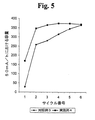
Zr26.6Ti9V5Ni38Cr5Mn16Sn0.4(すべて原子パーセント表示)の目標組成と99%より高い純度を有する200キログラムの原料を混合して真空誘導電気炉に入れ、溶融した後、鋼製の鋳型に注いで本研究のインゴットを形成した。そのインゴットのうちの20キログラムを、図2に表示のスケールアップ水素リアクターに入れた。水素化物化/脱水素化物化プロセスは、対照例2と同じであった。それらの放電電荷容量が表IIに記載されており、また、図5にプロットされている。この合金は、Al及びCo添加物を含んでおらず、また、制御下酸化反応で処理されなかった。試験したとき、この材料は、活性化するのが非常に遅かった。
(Control 3)
200 kg of raw material having a target composition of Zr 26.6 Ti 9 V 5 Ni 38 Cr 5 Mn 16 Sn 0.4 (all expressed in atomic percent) and a purity higher than 99% was mixed and placed in a vacuum induction electric furnace, After melting, it was poured into a steel mold to form the ingot for this study. 20 kilograms of the ingot were placed in the scale-up hydrogen reactor indicated in FIG. The hydride / dehydride process was the same as
(実施例4)
制御下酸化をスケールアップするため、冷却室、加熱室、及び、前述の冷却室を前述の加熱室に操作可能に接続する逆転式のネジまたはスクリューを有する2室型回転式水素リアクターを設計した(この2室型回転式水素リアクターの概略図については、図1を参照のこと)。固定式の水素リアクターも使用することもできるが、固定式の20kg用水素リアクターは、上述の微細な金属粉末の熱伝導度が悪いため、この微細な金属粉末を室温にまで冷却するのに15時間かそれ以上の長時間を要し得る。本発明の新規な2室型リアクターは、プロセス時間及び冷却時間を劇的に短縮する。
Example 4
To scale up controlled oxidation, a two-chamber rotary hydrogen reactor with a cooling chamber, a heating chamber, and a reversing screw or screw that operably connects the aforementioned cooling chamber to the aforementioned heating chamber was designed. (See FIG. 1 for a schematic diagram of this two-chamber rotary hydrogen reactor). A fixed hydrogen reactor can also be used, but the fixed 20 kg hydrogen reactor has a low thermal conductivity of the fine metal powder described above, so that the fine metal powder is cooled to room temperature by 15%. It can take hours or more. The novel two-chamber reactor of the present invention dramatically reduces process time and cooling time.
対照例3と同じバッチのインゴットから採取した20キログラムを、上述の回転式水素リアクターに入れた。図1から分かるように、スクリューに沿った粉末の輸送方向は、それらのリアクター・チャンバーの回転方向に依存している。水素化物化プロセス中には、粉末が冷却室に3時間滞留するような仕方で冷却用リアクターを回転させた。また、脱水素化プロセス中には、スクリューに沿って粉末を高温室に輸送するため、そのリアクターを別の向きに回転させた。粉末は、約3時間脱水素化物化された。脱水素化が終了すると、粉末を冷却室へ戻して1.5時間冷却するため、加熱室を逆方向に回転させた。粉末が冷却されると、温度上昇を約1℃に制限した状態で、その粉末を、80%Ar/20%O2を用いる3回の制御下酸化サイクルにかけた。試料装填を含む全体のプロセス時間は、約10.5時間を要した。そのようにして得られた粉末を電極の形態に作成し、対照例3の場合と同じ本式の満液電池構成下において試験した。比較のため、それらの試験結果が表IIに記載されており、また、図5にプロットされている。それらの試験結果は、多室型回転式水素リアクターを用いて制御下酸化反応で調製された水素貯蔵粉末を有する電極が、改善された初期活性化を有していることを示している。
Twenty kilograms taken from the same batch of ingot as in
(実施例5)
インゴットの別の20kgを、サンプル2の場合と同じ2室型回転式水素リアクターに入れた。この実験では、水素化物化時間を2時間から1.1時間に短縮し、そして、脱水素化物化時間を3時間から1.6時間に短縮した。冷却と制御下酸化を合わせたサイクルは、2.7時間に短縮され、そして、比較的大きな酸化剤流量を含んだ。そのようにして得られた粉末を電極の形態に作成し、前記の場合と同じ条件下で試験した。それらの試験結果は、制御下酸化反応を受けた材料の活性化し易さが、対照サンプルに比べ、著しく改善されていることを示した。
(Example 5)
Another 20 kg of ingot was placed in the same two-chamber rotary hydrogen reactor as in
【表2】
本発明に従って使用するのに適した特に好ましい水素貯蔵粉末は、1999年4月12日に出願された同時係属の米国特許出願第09/290,633号(この公報の開示内容は、参照により本明細書に組み入れられる)に開示されている、新たな、改善された一連の合金である。その出願公報には、ベース合金と少なくとも1種類の変性元素とを含む新規な一連の電気化学的水素貯蔵合金が開示されており、そのベース合金は、おおよそ、0.1%から60%までのTi、0.1%から40%までのZr、0%から60%までのV、0.1%から57%までのNi、5%から22%までのMn、及び0%から56%までのCrを含んでいる。変性剤合金は、ベース合金Ti−V−Zr−Ni−Mn−Crの電気化学的水素貯蔵合金を上回る高い充電/放電率能力により特徴付けられる。そのTi−V−Zr−Ni−Mn−Crの電気化学的水素貯蔵合金は、好ましくは、1種類もしくはそれ以上の種類の以下の元素を含んでいる:0.1%から10.0%までのAl、0.1%から10%までのCo、0%から3.5%までのFe、及び0.1%から3.0%までのSn。また、このTi−V−Zr−Ni−Mn−Crは、金属触媒粒子も含んでいてよい。
A particularly preferred hydrogen storage powder suitable for use in accordance with the present invention is copending US patent application Ser. No. 09 / 290,633 filed Apr. 12, 1999 (the disclosure of this publication is incorporated herein by reference). A new and improved series of alloys disclosed in the specification. The application publication discloses a novel series of electrochemical hydrogen storage alloys comprising a base alloy and at least one modifying element, the base alloy comprising approximately 0.1% to 60% Ti, 0.1% to 40% Zr, 0% to 60% V, 0.1% to 57% Ni, 5% to 22% Mn, and 0% to 56% Contains Cr. The modifier alloy is characterized by a high charge / discharge rate capability over the base alloy Ti-V-Zr-Ni-Mn-Cr electrochemical hydrogen storage alloy. The Ti-V-Zr-Ni-Mn-Cr electrochemical hydrogen storage alloy preferably contains one or more of the following elements: 0.1% to 10.0% Al, 0.1% to 10% Co, 0% to 3.5% Fe, and 0.1% to 3.0% Sn. Moreover, this Ti-V-Zr-Ni-Mn-Cr may also contain metal catalyst particles.
添付図面及び上記の記載において本発明を詳細に説明してきたが、それは、限定的なものではなく、例証的な性質ものと考えるべきであって、好ましいその実施形態のみが充分に示され説明されたのみであって、そして、本発明の精神の範囲内にあるすべての変更及び修正が保護されるべく意図されていることを理解すべきである。
【図面の簡単な説明】
【図1】図1は、本発明に従って制御下酸化反応を提供するための回転式水素リアクターの概略図であり;
【図2】図2は、固定式水素リアクターの概略図であり;
【図3】図3は、本発明に従って水素貯蔵材料を製造するための方法に関する流れ図であり;
【図4】図4は、本発明に従って調製された水素貯蔵材料を有する電極と対照サンプルの初期電極活性化を比較するグラフであり;そして
【図5】図5は、本発明に従って調製された水素貯蔵材料を用いた電極と対照サンプルの初期電極活性化を比較するグラフである。
While the invention has been described in detail in the accompanying drawings and foregoing description, it is to be considered as illustrative and not restrictive and only the preferred embodiments thereof have been fully shown and described. It should be understood that all changes and modifications within the spirit of the invention are intended to be protected.
[Brief description of the drawings]
FIG. 1 is a schematic diagram of a rotary hydrogen reactor for providing a controlled oxidation reaction according to the present invention;
FIG. 2 is a schematic diagram of a stationary hydrogen reactor;
FIG. 3 is a flow diagram for a method for producing a hydrogen storage material according to the present invention;
FIG. 4 is a graph comparing the initial electrode activation of an electrode having a hydrogen storage material prepared in accordance with the present invention and a control sample; and FIG. 5 is prepared in accordance with the present invention. Figure 2 is a graph comparing the initial electrode activation of an electrode using a hydrogen storage material and a control sample.
Claims (18)
水素貯蔵粉末を初期温度で提供するステップと
前記水素貯蔵粉末が前記水素貯蔵粉末の前記初期温度よりも5℃以内で高い予め定められた温度に達するまで前記粉末に酸化性雰囲気を付加し、酸化を制御するために前記酸化性雰囲気の付加を前記粉末が冷却されるまで停止し、そして、前記粉末の粒子に酸化物層が形成されるまでこの付加と停止を繰り返すことにより、前記水素貯蔵粉末を酸化性雰囲気に晒すステップと
を含む、水素貯蔵材料粒子の製造方法。
A method for producing hydrogen storage material particles comprising:
The hydrogen storage powder is added an oxidizing atmosphere to said powder to said hydrogen storage powder and the step of providing an initial temperature reaches the initial temperature a predetermined temperature higher within 5 ° C. than the hydrogen storage powder, oxide The hydrogen storage powder is controlled by stopping the addition of the oxidizing atmosphere until the powder is cooled, and repeating the addition and stop until an oxide layer is formed on the powder particles. Exposing the material to an oxidizing atmosphere. A method for producing hydrogen storage material particles.
The method of claim 1, wherein the powder is provided at an initial temperature just prior to oxidation, and the predetermined temperature is a temperature within 1 ° C. higher than the initial temperature.
The method of claim 1, wherein the hydrogen storage powder is provided by a process comprising grinding by hydridation of bulk material at a temperature of 75 ° C. or less.
The method of claim 1, wherein the hydrogen storage powder is agitated during the step of exposing the hydrogen storage powder to an oxidizing atmosphere.
The method of claim 1, further comprising adding a passivating material to the hydrogen storage powder prior to exposing the hydrogen storage powder to an oxidizing atmosphere.
The method of claim 1, wherein the hydrogen storage powder is an AB type 2 hydrogen storage alloy.
The method of claim 4 , wherein stirring in the step of exposing the hydrogen storage powder to an oxidizing atmosphere comprises stirring the powder to provide an anti-ignitable oxide surface layer for each particle of the hydrogen storage powder. .
The method of claim 1, wherein the hydrogen storage powder is an electrochemical hydrogen storage material.
The method of claim 1, wherein the hydrogen storage powder is a gas phase hydrogen storage material.
The method of claim 1, wherein the oxidizing atmosphere includes at least one oxidizing gas and at least one non-oxidizing gas.
The method of claim 10 , wherein the oxidizing gas comprises O 2 .
The method of claim 1, wherein the oxidizing atmosphere comprises greater than 70% non-oxidizing agent by weight and 20% to 30% oxidizing agent by weight.
6. The method of claim 5 , wherein the passivating material comprises at least one element selected from the group consisting of Cr, Fe, Co, Ni, Cu, Zn, Mo, Ta, and W.
6. The method of claim 5 , wherein the passivating material is a hydrophobic organic compound.
The method according to claim 5 , wherein the passivating material is a layered sulfide compound having at least one element selected from the group consisting of Nb, Mo, Ta, and W.
The method of claim 1, wherein the hydrogen storage material comprises at least one sacrificial modifier.
The method according to claim 16 , wherein the sacrificial modifier comprises at least one element selected from the group consisting of Co, Al, Fe, Li, K, Na, Sc, Y, and Mg.
請求項1から17のいずれか1項に記載の水素貯蔵材料粒子を提供するステップと、
前記水素貯蔵材料粒子を陰極の形態に形成するステップと、
前記水素貯蔵材料粒子を活性化するステップと
を含む、電気化学的電池用陰極の製造方法。 A method for producing a cathode for an electrochemical battery comprising:
Providing the hydrogen storage material particles of any one of claims 1 to 17 ;
Forming the hydrogen storage material particles in the form of a cathode;
Activating the hydrogen storage material particles. A method for producing a cathode for an electrochemical cell.
Applications Claiming Priority (3)
| Application Number | Priority Date | Filing Date | Title |
|---|---|---|---|
| US09/575,313 US6461766B1 (en) | 1998-08-27 | 2000-05-19 | Hydrogen storage powder and process for preparing the same |
| US09/575,313 | 2000-05-19 | ||
| PCT/US2001/016344 WO2001091210A1 (en) | 2000-05-19 | 2001-05-18 | Hydrogen storage powder and process for preparing the same |
Publications (3)
| Publication Number | Publication Date |
|---|---|
| JP2003534637A JP2003534637A (en) | 2003-11-18 |
| JP2003534637A5 JP2003534637A5 (en) | 2012-03-22 |
| JP5250170B2 true JP5250170B2 (en) | 2013-07-31 |
Family
ID=24299803
Family Applications (1)
| Application Number | Title | Priority Date | Filing Date |
|---|---|---|---|
| JP2001587503A Expired - Fee Related JP5250170B2 (en) | 2000-05-19 | 2001-05-18 | Hydrogen storage powder and its preparation process |
Country Status (10)
| Country | Link |
|---|---|
| US (3) | US6461766B1 (en) |
| EP (1) | EP1293003A4 (en) |
| JP (1) | JP5250170B2 (en) |
| CN (2) | CN101066559A (en) |
| AU (1) | AU2001264737A1 (en) |
| BR (1) | BR0110983A (en) |
| CA (1) | CA2409218A1 (en) |
| MX (1) | MXPA02011364A (en) |
| TW (1) | TW531919B (en) |
| WO (1) | WO2001091210A1 (en) |
Families Citing this family (34)
| Publication number | Priority date | Publication date | Assignee | Title |
|---|---|---|---|---|
| US6461766B1 (en) * | 1998-08-27 | 2002-10-08 | Ovonic Battery Company, Inc. | Hydrogen storage powder and process for preparing the same |
| US6270719B1 (en) * | 1999-04-12 | 2001-08-07 | Ovonic Battery Company, Inc. | Modified electrochemical hydrogen storage alloy having increased capacity, rate capability and catalytic activity |
| US6841512B1 (en) * | 1999-04-12 | 2005-01-11 | Ovonic Battery Company, Inc. | Finely divided metal catalyst and method for making same |
| US6589686B2 (en) * | 2001-02-28 | 2003-07-08 | Ovonic Battery Company, Inc. | Method of fuel cell activation |
| US6864002B1 (en) * | 2001-10-19 | 2005-03-08 | Christopher K. Dyer | Fuel cell system and method for producing electrical energy |
| US7169489B2 (en) | 2002-03-15 | 2007-01-30 | Fuelsell Technologies, Inc. | Hydrogen storage, distribution, and recovery system |
| US7399325B1 (en) | 2002-03-15 | 2008-07-15 | Fuelsell Technologies, Inc. | Method and apparatus for a hydrogen fuel cassette distribution and recovery system |
| US20040016769A1 (en) * | 2002-03-15 | 2004-01-29 | Redmond Scott D. | Hydrogen storage, distribution, and recovery system |
| JP4183959B2 (en) * | 2002-03-22 | 2008-11-19 | 株式会社日本製鋼所 | Method for producing hydrogen storage alloy |
| WO2004061981A1 (en) * | 2003-01-06 | 2004-07-22 | Showa Denko K. K. | Boron phosphide-based semiconductor light-emitting device and production method thereof |
| US6830725B2 (en) * | 2003-04-01 | 2004-12-14 | Texaco Ovonic Battery Systems, Llc | Hydrogen storage alloys having a high porosity surface layer |
| US7250386B2 (en) * | 2003-07-18 | 2007-07-31 | Energy Conversion Devices, Inc. | Quantum limit catalysts and hydrogen storage materials |
| US7175826B2 (en) * | 2003-12-29 | 2007-02-13 | General Electric Company | Compositions and methods for hydrogen storage and recovery |
| NO325620B1 (en) * | 2003-10-21 | 2008-06-30 | Revolt Technology Ltd | Electrode, Method of Preparation thereof, Metal / Air Fuel Cell and Metal Hydride Battery Cell |
| JP4908778B2 (en) * | 2004-06-30 | 2012-04-04 | キヤノン株式会社 | Method for producing catalyst layer of polymer electrolyte fuel cell and method for producing polymer electrolyte fuel cell |
| US20060057019A1 (en) | 2004-09-16 | 2006-03-16 | Kwo Young | Hydrogen storage alloys having reduced PCT hysteresis |
| US20070141464A1 (en) * | 2005-12-21 | 2007-06-21 | Qunjian Huang | Porous metal hydride electrode |
| JP5685533B2 (en) * | 2008-08-08 | 2015-03-18 | ヘンケル アイピー アンド ホールディング ゲゼルシャフト ミット ベシュレンクテル ハフツング | Low temperature curing composition |
| US8246903B2 (en) * | 2008-09-09 | 2012-08-21 | H.C. Starck Inc. | Dynamic dehydriding of refractory metal powders |
| DE102009018874A1 (en) * | 2009-04-24 | 2010-11-04 | Systec System- Und Anlagentechnik Gmbh & Co.Kg | Powdery electrode material consists of nickel, oxygen and/or hydrogen, or tetravalent nickel oxide, alkali metal, transition metals such as cobalt, vanadium, tungsten, iridium, tantalum and/or chromium and impurities |
| FR2950876B1 (en) * | 2009-10-07 | 2012-02-10 | Commissariat Energie Atomique | METHOD FOR TREATING A GETTER MATERIAL AND METHOD FOR ENCAPSULATING SUCH A GETTER MATERIAL |
| WO2012166808A2 (en) * | 2011-06-01 | 2012-12-06 | Target Technology International, Ltd. | Nickel alloys for hydrogen storage and the generation of energy therefrom |
| CN103894602B (en) * | 2012-12-27 | 2017-02-08 | 北京有色金属研究总院 | Surface treatment method for improving cycle life of rare earth magnesium based hydrogen storage alloy |
| EP2941490B1 (en) * | 2013-01-07 | 2024-08-21 | Ovonic Battery Company, Inc. | Metal hydride alloy |
| US8877378B2 (en) | 2013-01-07 | 2014-11-04 | Ovonic Battery Company, Inc. | Metal hydride alloy with catalyst particles and channels |
| US9350014B2 (en) * | 2013-01-07 | 2016-05-24 | Ovonic Battery Company, Inc. | Nanoscale nickel-based catalytic material |
| US20140194282A1 (en) * | 2013-01-07 | 2014-07-10 | Ovonic Battery Company, Inc. | Metal hydride alloy with catalytic particles |
| CN110820031A (en) * | 2019-11-19 | 2020-02-21 | 有研工程技术研究院有限公司 | Preparation method of miniature getter |
| US11266965B1 (en) | 2021-01-14 | 2022-03-08 | Shandong University | Ultra-low-speed rotating low-strain high-filling-rate hydrogen storage alloy reaction device and technology |
| WO2023004016A1 (en) | 2021-07-23 | 2023-01-26 | Harnyss Ip, Llc | 3d printed hydrogen storage systems using non-pyrophoric hydrogen storage alloys |
| CN113735057A (en) * | 2021-08-31 | 2021-12-03 | 苏州睿分电子科技有限公司 | Activation-free hydrogen storage material and preparation method and device thereof |
| CN114381644B (en) * | 2021-12-10 | 2022-10-21 | 厚普清洁能源(集团)股份有限公司 | Vanadium-titanium-based hydrogen storage alloy powder and preparation method thereof |
| CN114619026B (en) * | 2022-03-15 | 2024-01-12 | 厦门厦钨氢能科技有限公司 | Composite solid hydrogen storage material and preparation method thereof |
| CN115519119A (en) * | 2022-09-23 | 2022-12-27 | 江苏智仁景行新材料研究院有限公司 | Aluminum alloy powder containing endogenous hydride and preparation method thereof |
Family Cites Families (33)
| Publication number | Priority date | Publication date | Assignee | Title |
|---|---|---|---|---|
| US4457136A (en) * | 1981-03-23 | 1984-07-03 | Sekisui Kagaku Kogyo Kabushiki Kaisha | Metal hydride reactor |
| US4402915A (en) * | 1981-05-06 | 1983-09-06 | Sekisui Kagaku Kogyo Kabushiki Kaisha | Metal hydride reactor |
| US4623597A (en) * | 1982-04-28 | 1986-11-18 | Energy Conversion Devices, Inc. | Rechargeable battery and electrode used therein |
| US4551400A (en) * | 1984-04-18 | 1985-11-05 | Energy Conversion Devices, Inc. | Hydrogen storage materials and methods of sizing and preparing the same for electrochemical applications |
| US4923770A (en) * | 1985-03-29 | 1990-05-08 | The Standard Oil Company | Amorphous metal alloy compositions for reversible hydrogen storage and electrodes made therefrom |
| JPS62167201A (en) * | 1986-01-17 | 1987-07-23 | Daido Steel Co Ltd | Method for activating hydrogen storage alloy |
| US4716088A (en) * | 1986-12-29 | 1987-12-29 | Energy Conversion Devices, Inc. | Activated rechargeable hydrogen storage electrode and method |
| US4728586A (en) * | 1986-12-29 | 1988-03-01 | Energy Conversion Devices, Inc. | Enhanced charge retention electrochemical hydrogen storage alloys and an enhanced charge retention electrochemical cell |
| US4893756A (en) | 1988-09-22 | 1990-01-16 | Energy Conversion Devices, Inc. | Hydride reactor apparatus for hydrogen comminution of metal hydride hydrogen storage material |
| US5536591A (en) * | 1990-04-26 | 1996-07-16 | Ovonic Battery Company, Inc. | Electrochemical hydrogen storage alloys for nickel metal hydride batteries |
| US5185221A (en) * | 1992-02-06 | 1993-02-09 | Gates Energy Products, Inc. | Metal hydride electrode and electrochemical cell |
| US5248510A (en) * | 1992-02-18 | 1993-09-28 | Hughes Aircraft Company | Cobalt oxide passivation of nickel battery electrode substrates |
| DE4343321A1 (en) * | 1993-12-18 | 1995-06-22 | Varta Batterie | Electric accumulator |
| US5695530A (en) * | 1994-03-14 | 1997-12-09 | Hong; Kuochih | Method for making high charging efficiency and fast oxygen recombination rechargeable hydride batteries |
| WO1995027315A1 (en) * | 1994-03-31 | 1995-10-12 | Motorola, Inc. | Improved metal hydride hydrogen storage electrodes |
| CN1145694A (en) * | 1994-03-31 | 1997-03-19 | 摩托罗拉公司 | Improved metal hydride hydrogen storage electrodes |
| US5451474A (en) * | 1994-04-04 | 1995-09-19 | Motorola, Inc. | Metal hydride hydrogen storage electrodes |
| US5616432A (en) * | 1994-06-14 | 1997-04-01 | Ovonic Battery Company, Inc. | Electrochemical hydrogen storage alloys and batteries fabricated from Mg containing base alloys |
| CA2206252A1 (en) * | 1994-12-22 | 1996-06-27 | Lu Ming | Magnesium mechanical alloys for thermal hydrogen storage |
| JP3016064B2 (en) * | 1995-09-27 | 2000-03-06 | 古河電池株式会社 | Method for producing hydrogen storage alloy powder for battery |
| US5840440A (en) * | 1995-11-20 | 1998-11-24 | Ovonic Battery Company, Inc. | Hydrogen storage materials having a high density of non-conventional useable hydrogen storing sites |
| US5682592A (en) * | 1996-07-16 | 1997-10-28 | Korea Institute Of Science And Technology | Fabrication method for paste-type metal hydride electrode |
| JP3223858B2 (en) * | 1996-12-24 | 2001-10-29 | 松下電器産業株式会社 | Alkaline storage battery, its positive electrode active material, and method for producing the same |
| EP0851515A3 (en) * | 1996-12-27 | 2004-10-27 | Canon Kabushiki Kaisha | Powdery material, electrode member, method for manufacturing same and secondary cell |
| US5932372A (en) * | 1997-01-02 | 1999-08-03 | Lightyear Technologies Inc. | Composite materials, processes for manufacturing the composites, composite electrode, hydrogen occluding composite, and electrochemical cell utilizing the composite |
| JPH10195575A (en) * | 1997-01-10 | 1998-07-28 | Mitsubishi Materials Corp | Hydrogen storage alloy excellent in initial activity |
| JPH11130401A (en) * | 1997-10-29 | 1999-05-18 | Toyota Central Res & Dev Lab Inc | High activation treatment of hydrogen storage alloy |
| EP0940865A3 (en) * | 1998-03-05 | 2004-11-03 | Matsushita Electric Industrial Co., Ltd | Active materials for the positive electrode in alkaline storage battery and the manufacturing method of them |
| JPH11339789A (en) * | 1998-05-26 | 1999-12-10 | Toshiba Battery Co Ltd | Metal-oxide/hydrogen storage battery |
| US6461766B1 (en) * | 1998-08-27 | 2002-10-08 | Ovonic Battery Company, Inc. | Hydrogen storage powder and process for preparing the same |
| US6120936A (en) * | 1998-08-27 | 2000-09-19 | Ovonic Battery Company, Inc. | Method for powder formation of a hydrogen storage alloy |
| JP2000073101A (en) * | 1998-08-27 | 2000-03-07 | Daido Steel Co Ltd | Production of hydrogen storage alloy powder |
| US6270719B1 (en) * | 1999-04-12 | 2001-08-07 | Ovonic Battery Company, Inc. | Modified electrochemical hydrogen storage alloy having increased capacity, rate capability and catalytic activity |
-
2000
- 2000-05-19 US US09/575,313 patent/US6461766B1/en not_active Expired - Lifetime
-
2001
- 2001-05-16 US US09/859,164 patent/US6740448B2/en not_active Expired - Lifetime
- 2001-05-18 BR BR0110983-9A patent/BR0110983A/en not_active Application Discontinuation
- 2001-05-18 CN CNA2007101051710A patent/CN101066559A/en active Pending
- 2001-05-18 EP EP01939193A patent/EP1293003A4/en not_active Withdrawn
- 2001-05-18 CN CNB018130720A patent/CN1327549C/en not_active Expired - Fee Related
- 2001-05-18 MX MXPA02011364A patent/MXPA02011364A/en not_active Application Discontinuation
- 2001-05-18 TW TW090111880A patent/TW531919B/en not_active IP Right Cessation
- 2001-05-18 CA CA002409218A patent/CA2409218A1/en not_active Abandoned
- 2001-05-18 WO PCT/US2001/016344 patent/WO2001091210A1/en active Application Filing
- 2001-05-18 JP JP2001587503A patent/JP5250170B2/en not_active Expired - Fee Related
- 2001-05-18 AU AU2001264737A patent/AU2001264737A1/en not_active Abandoned
-
2002
- 2002-10-07 US US10/266,193 patent/US6789757B2/en not_active Expired - Fee Related
Also Published As
| Publication number | Publication date |
|---|---|
| US20030148180A1 (en) | 2003-08-07 |
| WO2001091210A1 (en) | 2001-11-29 |
| CN1327549C (en) | 2007-07-18 |
| BR0110983A (en) | 2003-12-30 |
| US6461766B1 (en) | 2002-10-08 |
| EP1293003A1 (en) | 2003-03-19 |
| JP2003534637A (en) | 2003-11-18 |
| AU2001264737A1 (en) | 2001-12-03 |
| CN101066559A (en) | 2007-11-07 |
| MXPA02011364A (en) | 2004-01-26 |
| EP1293003A4 (en) | 2006-10-25 |
| US6789757B2 (en) | 2004-09-14 |
| TW531919B (en) | 2003-05-11 |
| CN1443377A (en) | 2003-09-17 |
| US6740448B2 (en) | 2004-05-25 |
| CA2409218A1 (en) | 2001-11-29 |
| US20030038197A1 (en) | 2003-02-27 |
Similar Documents
| Publication | Publication Date | Title |
|---|---|---|
| JP5250170B2 (en) | Hydrogen storage powder and its preparation process | |
| JP2003534637A5 (en) | ||
| JP2951331B2 (en) | Active material for hydrogen storage electrode, method for forming the same, and electrochemical application | |
| EP0783040B1 (en) | Rare earth metal-nickel hydrogen storage alloy, process for producing the same, and anode for nickel-hydrogen rechargeable battery | |
| MXPA00012015A (en) | Modified electrochemical hydrogen storage alloy having increased capacity, rate capability and catalytic activity. | |
| JP3034915B2 (en) | Manufacturing method of hydrogen storage alloy | |
| JP2008513605A (en) | Hydrogen storage alloy with reduced PCT hysteresis | |
| US5985054A (en) | Age precipitation-containing rare earth metal-nickel alloy | |
| KR101904499B1 (en) | PROCESS FOR PRODUCTION OF (RARE EARTH)-Mg-Ni-BASED HYDROGEN STORAGE ALLOY | |
| US6120936A (en) | Method for powder formation of a hydrogen storage alloy | |
| Yu et al. | A Ti-V-based bcc phase alloy for use as metal hydride electrode with high discharge capacity | |
| CN108588521A (en) | A kind of high capacity Mg-Cu-Ni ternary hydrogen-storage alloys and preparation method thereof | |
| Yuexiang et al. | Characteristics of a low-cobalt AB5-type hydrogen storage alloy obtained by a gas-atomization processing | |
| Lenain et al. | Electrochemical properties of AB5-type hydride-forming compounds prepared by mechanical alloying | |
| CN117821829B (en) | Ti-Fe-based electrode alloy for Ni-MH battery and preparation method thereof | |
| JPH0763007B2 (en) | Manufacturing method of hydrogen storage electrode | |
| JPH09302436A (en) | Magnesium type hydrogen storage material and its production | |
| CA1269083A (en) | Hydrogen storage materials and methods of sizing and preparing the same for electrochemical applications | |
| JP2002540575A (en) | Metal-containing electrode material and its manufacturing method | |
| CN116053491A (en) | High-capacity easy-activation RE-Ti-Fe-Mn-based hydrogen storage alloy for fuel cell and preparation method thereof | |
| JPH09302431A (en) | Production of hydrogen storage alloy powder | |
| JPH08143986A (en) | Production of hydrogen storage alloy | |
| JPH07157801A (en) | Hydrogen storage alloy, its production and enclosed secondary battery using the same |
Legal Events
| Date | Code | Title | Description |
|---|---|---|---|
| A621 | Written request for application examination |
Free format text: JAPANESE INTERMEDIATE CODE: A621 Effective date: 20080312 |
|
| A131 | Notification of reasons for refusal |
Free format text: JAPANESE INTERMEDIATE CODE: A131 Effective date: 20111101 |
|
| A524 | Written submission of copy of amendment under article 19 pct |
Free format text: JAPANESE INTERMEDIATE CODE: A524 Effective date: 20120131 |
|
| A131 | Notification of reasons for refusal |
Free format text: JAPANESE INTERMEDIATE CODE: A131 Effective date: 20121009 |
|
| A521 | Request for written amendment filed |
Free format text: JAPANESE INTERMEDIATE CODE: A523 Effective date: 20121107 |
|
| TRDD | Decision of grant or rejection written | ||
| A01 | Written decision to grant a patent or to grant a registration (utility model) |
Free format text: JAPANESE INTERMEDIATE CODE: A01 Effective date: 20130326 |
|
| A61 | First payment of annual fees (during grant procedure) |
Free format text: JAPANESE INTERMEDIATE CODE: A61 Effective date: 20130415 |
|
| R150 | Certificate of patent or registration of utility model |
Free format text: JAPANESE INTERMEDIATE CODE: R150 Ref document number: 5250170 Country of ref document: JP Free format text: JAPANESE INTERMEDIATE CODE: R150 |
|
| FPAY | Renewal fee payment (event date is renewal date of database) |
Free format text: PAYMENT UNTIL: 20160419 Year of fee payment: 3 |
|
| R250 | Receipt of annual fees |
Free format text: JAPANESE INTERMEDIATE CODE: R250 |
|
| R250 | Receipt of annual fees |
Free format text: JAPANESE INTERMEDIATE CODE: R250 |
|
| R250 | Receipt of annual fees |
Free format text: JAPANESE INTERMEDIATE CODE: R250 |
|
| LAPS | Cancellation because of no payment of annual fees |