JP5249471B2 - Ultrasonic probe - Google Patents

Ultrasonic probe Download PDF

Info

Publication number
JP5249471B2
JP5249471B2 JP2012549578A JP2012549578A JP5249471B2 JP 5249471 B2 JP5249471 B2 JP 5249471B2 JP 2012549578 A JP2012549578 A JP 2012549578A JP 2012549578 A JP2012549578 A JP 2012549578A JP 5249471 B2 JP5249471 B2 JP 5249471B2
Authority
JP
Japan
Prior art keywords
ultrasonic
longitudinal axis
probe
ultrasonic probe
main body
Prior art date
Legal status (The legal status is an assumption and is not a legal conclusion. Google has not performed a legal analysis and makes no representation as to the accuracy of the status listed.)
Active
Application number
JP2012549578A
Other languages
Japanese (ja)
Other versions
JPWO2012118018A1 (en
Inventor
庸高 銅
Current Assignee (The listed assignees may be inaccurate. Google has not performed a legal analysis and makes no representation or warranty as to the accuracy of the list.)
Olympus Medical Systems Corp
Original Assignee
Olympus Medical Systems Corp
Priority date (The priority date is an assumption and is not a legal conclusion. Google has not performed a legal analysis and makes no representation as to the accuracy of the date listed.)
Filing date
Publication date
Application filed by Olympus Medical Systems Corp filed Critical Olympus Medical Systems Corp
Application granted granted Critical
Publication of JP5249471B2 publication Critical patent/JP5249471B2/en
Publication of JPWO2012118018A1 publication Critical patent/JPWO2012118018A1/en
Active legal-status Critical Current
Anticipated expiration legal-status Critical

Links

Images

Classifications

    • AHUMAN NECESSITIES
    • A61MEDICAL OR VETERINARY SCIENCE; HYGIENE
    • A61BDIAGNOSIS; SURGERY; IDENTIFICATION
    • A61B17/00Surgical instruments, devices or methods, e.g. tourniquets
    • A61B17/32Surgical cutting instruments
    • A61B17/320068Surgical cutting instruments using mechanical vibrations, e.g. ultrasonic
    • AHUMAN NECESSITIES
    • A61MEDICAL OR VETERINARY SCIENCE; HYGIENE
    • A61NELECTROTHERAPY; MAGNETOTHERAPY; RADIATION THERAPY; ULTRASOUND THERAPY
    • A61N7/00Ultrasound therapy
    • AHUMAN NECESSITIES
    • A61MEDICAL OR VETERINARY SCIENCE; HYGIENE
    • A61BDIAGNOSIS; SURGERY; IDENTIFICATION
    • A61B18/00Surgical instruments, devices or methods for transferring non-mechanical forms of energy to or from the body
    • A61B18/04Surgical instruments, devices or methods for transferring non-mechanical forms of energy to or from the body by heating
    • A61B18/12Surgical instruments, devices or methods for transferring non-mechanical forms of energy to or from the body by heating by passing a current through the tissue to be heated, e.g. high-frequency current
    • A61B18/14Probes or electrodes therefor
    • A61B18/1442Probes having pivoting end effectors, e.g. forceps
    • A61B18/1445Probes having pivoting end effectors, e.g. forceps at the distal end of a shaft, e.g. forceps or scissors at the end of a rigid rod
    • AHUMAN NECESSITIES
    • A61MEDICAL OR VETERINARY SCIENCE; HYGIENE
    • A61BDIAGNOSIS; SURGERY; IDENTIFICATION
    • A61B17/00Surgical instruments, devices or methods, e.g. tourniquets
    • A61B2017/00526Methods of manufacturing
    • AHUMAN NECESSITIES
    • A61MEDICAL OR VETERINARY SCIENCE; HYGIENE
    • A61BDIAGNOSIS; SURGERY; IDENTIFICATION
    • A61B17/00Surgical instruments, devices or methods, e.g. tourniquets
    • A61B17/22Implements for squeezing-off ulcers or the like on the inside of inner organs of the body; Implements for scraping-out cavities of body organs, e.g. bones; Calculus removers; Calculus smashing apparatus; Apparatus for removing obstructions in blood vessels, not otherwise provided for
    • A61B17/22004Implements for squeezing-off ulcers or the like on the inside of inner organs of the body; Implements for scraping-out cavities of body organs, e.g. bones; Calculus removers; Calculus smashing apparatus; Apparatus for removing obstructions in blood vessels, not otherwise provided for using mechanical vibrations, e.g. ultrasonic shock waves
    • A61B17/22012Implements for squeezing-off ulcers or the like on the inside of inner organs of the body; Implements for scraping-out cavities of body organs, e.g. bones; Calculus removers; Calculus smashing apparatus; Apparatus for removing obstructions in blood vessels, not otherwise provided for using mechanical vibrations, e.g. ultrasonic shock waves in direct contact with, or very close to, the obstruction or concrement
    • A61B2017/22014Implements for squeezing-off ulcers or the like on the inside of inner organs of the body; Implements for scraping-out cavities of body organs, e.g. bones; Calculus removers; Calculus smashing apparatus; Apparatus for removing obstructions in blood vessels, not otherwise provided for using mechanical vibrations, e.g. ultrasonic shock waves in direct contact with, or very close to, the obstruction or concrement the ultrasound transducer being outside patient's body; with an ultrasound transmission member; with a wave guide; with a vibrated guide wire
    • A61B2017/22015Implements for squeezing-off ulcers or the like on the inside of inner organs of the body; Implements for scraping-out cavities of body organs, e.g. bones; Calculus removers; Calculus smashing apparatus; Apparatus for removing obstructions in blood vessels, not otherwise provided for using mechanical vibrations, e.g. ultrasonic shock waves in direct contact with, or very close to, the obstruction or concrement the ultrasound transducer being outside patient's body; with an ultrasound transmission member; with a wave guide; with a vibrated guide wire with details of the transmission member
    • AHUMAN NECESSITIES
    • A61MEDICAL OR VETERINARY SCIENCE; HYGIENE
    • A61BDIAGNOSIS; SURGERY; IDENTIFICATION
    • A61B17/00Surgical instruments, devices or methods, e.g. tourniquets
    • A61B17/32Surgical cutting instruments
    • A61B17/320068Surgical cutting instruments using mechanical vibrations, e.g. ultrasonic
    • A61B2017/320069Surgical cutting instruments using mechanical vibrations, e.g. ultrasonic for ablating tissue
    • AHUMAN NECESSITIES
    • A61MEDICAL OR VETERINARY SCIENCE; HYGIENE
    • A61BDIAGNOSIS; SURGERY; IDENTIFICATION
    • A61B17/00Surgical instruments, devices or methods, e.g. tourniquets
    • A61B17/32Surgical cutting instruments
    • A61B17/320068Surgical cutting instruments using mechanical vibrations, e.g. ultrasonic
    • A61B2017/320071Surgical cutting instruments using mechanical vibrations, e.g. ultrasonic with articulating means for working tip
    • AHUMAN NECESSITIES
    • A61MEDICAL OR VETERINARY SCIENCE; HYGIENE
    • A61BDIAGNOSIS; SURGERY; IDENTIFICATION
    • A61B17/00Surgical instruments, devices or methods, e.g. tourniquets
    • A61B17/32Surgical cutting instruments
    • A61B17/320068Surgical cutting instruments using mechanical vibrations, e.g. ultrasonic
    • A61B2017/320089Surgical cutting instruments using mechanical vibrations, e.g. ultrasonic node location
    • AHUMAN NECESSITIES
    • A61MEDICAL OR VETERINARY SCIENCE; HYGIENE
    • A61BDIAGNOSIS; SURGERY; IDENTIFICATION
    • A61B17/00Surgical instruments, devices or methods, e.g. tourniquets
    • A61B17/32Surgical cutting instruments
    • A61B17/320068Surgical cutting instruments using mechanical vibrations, e.g. ultrasonic
    • A61B17/320092Surgical cutting instruments using mechanical vibrations, e.g. ultrasonic with additional movable means for clamping or cutting tissue, e.g. with a pivoting jaw
    • A61B2017/320094Surgical cutting instruments using mechanical vibrations, e.g. ultrasonic with additional movable means for clamping or cutting tissue, e.g. with a pivoting jaw additional movable means performing clamping operation
    • AHUMAN NECESSITIES
    • A61MEDICAL OR VETERINARY SCIENCE; HYGIENE
    • A61BDIAGNOSIS; SURGERY; IDENTIFICATION
    • A61B18/00Surgical instruments, devices or methods for transferring non-mechanical forms of energy to or from the body
    • A61B2018/00315Surgical instruments, devices or methods for transferring non-mechanical forms of energy to or from the body for treatment of particular body parts
    • A61B2018/00345Vascular system
    • A61B2018/00404Blood vessels other than those in or around the heart
    • A61B2018/00428Severing
    • AHUMAN NECESSITIES
    • A61MEDICAL OR VETERINARY SCIENCE; HYGIENE
    • A61BDIAGNOSIS; SURGERY; IDENTIFICATION
    • A61B18/00Surgical instruments, devices or methods for transferring non-mechanical forms of energy to or from the body
    • A61B2018/00571Surgical instruments, devices or methods for transferring non-mechanical forms of energy to or from the body for achieving a particular surgical effect
    • A61B2018/00589Coagulation
    • AHUMAN NECESSITIES
    • A61MEDICAL OR VETERINARY SCIENCE; HYGIENE
    • A61BDIAGNOSIS; SURGERY; IDENTIFICATION
    • A61B18/00Surgical instruments, devices or methods for transferring non-mechanical forms of energy to or from the body
    • A61B2018/00994Surgical instruments, devices or methods for transferring non-mechanical forms of energy to or from the body combining two or more different kinds of non-mechanical energy or combining one or more non-mechanical energies with ultrasound
    • AHUMAN NECESSITIES
    • A61MEDICAL OR VETERINARY SCIENCE; HYGIENE
    • A61BDIAGNOSIS; SURGERY; IDENTIFICATION
    • A61B2217/00General characteristics of surgical instruments
    • A61B2217/002Auxiliary appliance
    • A61B2217/005Auxiliary appliance with suction drainage system

Abstract

An ultrasonic probe, which transmits ultrasonic vibrations from a proximal end to a distal end, includes a probe body including an outer peripheral portion provided along a longitudinal axis, and a void defining surface defining a void, which extends from a first perpendicular direction perpendicular to the longitudinal axis toward a second perpendicular direction opposite to the first perpendicular direction, in the probe body. The void is defined along the longitudinal axis from a first anti-node position of the ultrasonic vibrations to a second anti-node position of the ultrasonic vibrations different from the first anti-node position. At least a first-perpendicular-direction-side end of the void defining surface being continuous with the outer peripheral portion of the probe body.

Description

本発明は、超音波吸引装置等の超音波処置装置に用いられる超音波プローブに関する。   The present invention relates to an ultrasonic probe used in an ultrasonic treatment apparatus such as an ultrasonic suction apparatus.

特許文献1には、超音波吸引という処置と超音波凝固切開という処置を行う超音波処置装置が開示されている。この超音波処置装置は、基端から先端へ超音波振動を伝達する超音波プローブを備える。超音波吸引は、超音波振動している超音波プローブの先端面を用いて行われ、キャビテーションという物理現象を利用して行われる。具体的に説明すると、超音波振動により超音波プローブは毎秒数万回の高速振動を繰り返しているため、超音波プローブの先端面近傍では、周期的に圧力が変動する。圧力変動により微小時間だけ飽和蒸気圧より先端面近傍の圧力が低くなった際には、体腔内の液体あるいは超音波処置装置から生体組織の処置位置の近傍に送られた液体に微小な気泡(キャビティー)が生じる。そして、先端面近傍の圧力が大きくなる(圧縮する)際に作用する力により、発生した気泡が消滅する。以上のような物理現象を、キャビテーション現象という。気泡が消滅するときの衝撃エネルギーにより、肝細胞等の弾力性を有さない生体組織は破砕(shattered)、乳化される(emulsified)。超音波プローブの内部には、基端から先端まで吸引通路が貫通している。破砕、乳化された生体組織は、超音波プローブの先端の吸引口から吸引通路を通って、吸引回収される。以上のような作用が継続されることにより、生体組織が切除される。この際、血管等の弾力性の高い生体組織は衝撃が吸収されるため破砕され難く、生体組織が選択的に破砕される。ただし、キャビテーションにより生体組織が選択的に破砕されるが、超音波プローブの先端を生態組織の処置位置(患部)に留めた状態でキャビテーションによる処置を続けた場合、血管等の弾力性の高い生体組織も損傷する(damaged)可能性がある。このため、処置位置(患部)の表面に沿って超音波プローブが移動する状態で、キャビテーションによる処置が行われる。なお、超音波プローブでは基端から先端まで吸引通路が貫通しているため、超音波プローブは筒状に形成されている。   Patent Document 1 discloses an ultrasonic treatment apparatus that performs a treatment called ultrasonic suction and a treatment called ultrasonic coagulation and incision. This ultrasonic treatment apparatus includes an ultrasonic probe that transmits ultrasonic vibrations from the proximal end to the distal end. The ultrasonic suction is performed using the tip surface of the ultrasonic probe that is ultrasonically vibrated, and is performed using a physical phenomenon called cavitation. Specifically, since the ultrasonic probe repeats tens of thousands of high-speed vibrations per second due to the ultrasonic vibration, the pressure periodically fluctuates in the vicinity of the tip surface of the ultrasonic probe. When the pressure in the vicinity of the tip surface becomes lower than the saturated vapor pressure for a minute time due to the pressure fluctuation, a minute bubble (in the liquid in the body cavity or the liquid sent from the ultrasonic treatment device to the vicinity of the treatment position of the living tissue) Cavity) occurs. The generated bubbles disappear due to the force acting when the pressure in the vicinity of the front end surface increases (compresses). Such a physical phenomenon is called a cavitation phenomenon. Due to the impact energy when the bubbles disappear, biological tissues such as hepatocytes that do not have elasticity are shattered and emulsified. Inside the ultrasonic probe, a suction passage extends from the proximal end to the distal end. The crushed and emulsified living tissue is sucked and collected from the suction port at the tip of the ultrasonic probe through the suction passage. A living tissue is excised by continuing the above actions. At this time, a highly elastic living tissue such as a blood vessel is hardly crushed because the impact is absorbed, and the living tissue is selectively crushed. However, although the biological tissue is selectively crushed by cavitation, if the treatment by cavitation is continued with the tip of the ultrasonic probe held at the treatment position (affected part) of the ecological tissue, a highly elastic living body such as a blood vessel Tissues can also be damaged. For this reason, the treatment by cavitation is performed in a state where the ultrasonic probe moves along the surface of the treatment position (affected part). In the ultrasonic probe, since the suction passage penetrates from the proximal end to the distal end, the ultrasonic probe is formed in a cylindrical shape.

特開2005−27809号公報JP 2005-27809 A

前記特許文献1の超音波処置装置で用いられる筒状の超音波プローブは、柱状部材を孔開け加工することにより形成される。ここで、超音波プローブの材料となる柱状部材は、長手軸に沿った寸法が長く、長手軸に垂直な方向の寸法は小さい。このような細長い柱状部材の孔開け加工は、専用のドリルを用いて長時間要して行われる。したがって、超音波プローブの製造時の作業効率が低下し、超音波プローブの製造コストも高くなる。   The cylindrical ultrasonic probe used in the ultrasonic treatment apparatus of Patent Document 1 is formed by drilling a columnar member. Here, the columnar member that is the material of the ultrasonic probe has a long dimension along the longitudinal axis and a small dimension in a direction perpendicular to the longitudinal axis. Such a long and narrow columnar member is drilled for a long time using a dedicated drill. Therefore, the work efficiency at the time of manufacturing the ultrasonic probe is reduced, and the manufacturing cost of the ultrasonic probe is increased.

本発明は前記課題に着目してなされたものであり、その目的とするところは、効率よく、低コストで製造可能な超音波プローブを提供することにある。   The present invention has been made paying attention to the above problems, and an object of the present invention is to provide an ultrasonic probe that can be manufactured efficiently and at low cost.

前記目的を達成するため、本発明のある態様では、超音波振動を伝達する超音波プローブであって、基端から先端まで長手軸に沿って外周部が設けられるプローブ本体と、前記超音波振動の第1の腹位置から前記第1の腹位置とは異なる前記超音波振動の第2の腹位置まで前記長手軸に沿って全長に亘って、前記プローブ本体の前記外周部において開口する空洞部を、前記長手軸に沿って規定する空洞規定面と、を備える超音波プローブを提供する。 To achieve the above object, in one aspect of the present invention, an ultrasonic probe for transmitting ultrasonic vibration, a probe body outer peripheral portion along the longitudinal axis is provided from the proximal end to the distal end, the ultrasonic vibrations A cavity that opens in the outer peripheral portion of the probe body over the entire length from the first antinode position to the second antinode position of the ultrasonic vibration different from the first antinode position along the longitudinal axis. An ultrasonic probe comprising: a cavity defining surface that defines a longitudinal axis along the longitudinal axis.

本発明によれば、効率よく、低コストで製造可能な超音波プローブを提供することができる。   ADVANTAGE OF THE INVENTION According to this invention, the ultrasonic probe which can be manufactured efficiently and at low cost can be provided.

本発明の第1の実施形態に係る超音波処置装置を示す概略図。Schematic which shows the ultrasonic treatment apparatus which concerns on the 1st Embodiment of this invention. 第1の実施形態に係る振動子ユニットの構成を概略的に示す断面図。FIG. 3 is a cross-sectional view schematically showing the configuration of the vibrator unit according to the first embodiment. 第1の実施形態に係る超音波プローブを概略的に示す斜視図。1 is a perspective view schematically showing an ultrasonic probe according to a first embodiment. 第1の実施形態に係る超音波プローブを部材ごとに分解して概略的に示す斜視図。The perspective view which decomposes | disassembles and shows the ultrasonic probe which concerns on 1st Embodiment for every member roughly. 第1の実施形態に係る超音波プローブのプローブ本体の長手軸に垂直な断面を示す断面図。Sectional drawing which shows a cross section perpendicular | vertical to the longitudinal axis of the probe main body of the ultrasonic probe which concerns on 1st Embodiment. 第1の実施形態に係る超音波プローブとホーンとの間の構成を概略的に示す断面図。Sectional drawing which shows schematically the structure between the ultrasonic probe which concerns on 1st Embodiment, and a horn. 第1の実施形態に係る超音波プローブのプローブ本体と筒状部との間の構成を示す断面図。Sectional drawing which shows the structure between the probe main body and cylindrical part of the ultrasonic probe which concerns on 1st Embodiment. 第1の実施形態に係る超音波プローブのプローブ本体の製造方法を示す概略図。Schematic which shows the manufacturing method of the probe main body of the ultrasonic probe which concerns on 1st Embodiment. 第1の実施形態に係る超音波プローブのプローブ本体の図8とは別の製造方法を示す概略図。Schematic which shows the manufacturing method different from FIG. 8 of the probe main body of the ultrasonic probe which concerns on 1st Embodiment. 第1の実施形態に係る超音波プローブの図9Aの製造方法により形成されたプローブ本体の、長手軸に垂直な断面を示す断面図。Sectional drawing which shows a cross section perpendicular | vertical to a longitudinal axis of the probe main body formed by the manufacturing method of FIG. 9A of the ultrasonic probe which concerns on 1st Embodiment. 第1の実施形態の比較例に係る超音波プローブを概略的に示す斜視図。The perspective view which shows roughly the ultrasonic probe which concerns on the comparative example of 1st Embodiment. 第1の実施形態に係るシースに超音波プローブが挿通された状態を概略的に示す断面図。Sectional drawing which shows schematically the state by which the ultrasonic probe was penetrated by the sheath which concerns on 1st Embodiment. 第1の実施形態に係るシースと振動子ケースとの連結部の構成を概略的に示す断面図。Sectional drawing which shows schematically the structure of the connection part of the sheath and vibrator | oscillator case which concern on 1st Embodiment. 第1の実施形態の第1の変形例に係る超音波処置装置を示す概略図。Schematic which shows the ultrasonic treatment apparatus which concerns on the 1st modification of 1st Embodiment. 第1の実施形態の第2の変形例に係るシースに超音波プローブが挿通された状態を概略的に示す断面図。Sectional drawing which shows schematically the state by which the ultrasonic probe was penetrated by the sheath which concerns on the 2nd modification of 1st Embodiment. 第1の実施形態の第3の変形例に係る超音波プローブのプローブ本体を概略的に示す斜視図。The perspective view which shows schematically the probe main body of the ultrasonic probe which concerns on the 3rd modification of 1st Embodiment. 第1の実施形態の第4の変形例に係る超音波プローブのプローブ本体を概略的に示す斜視図。The perspective view which shows schematically the probe main body of the ultrasonic probe which concerns on the 4th modification of 1st Embodiment. 第1の実施形態の第4の変形例に係る超音波プローブのプローブ本体の長手軸に垂直な断面を示す断面図。Sectional drawing which shows a cross section perpendicular | vertical to the longitudinal axis of the probe main body of the ultrasonic probe which concerns on the 4th modification of 1st Embodiment. 第1の実施形態の第5の変形例に係る超音波プローブの先端部の構成を概略的に示す断面図。Sectional drawing which shows schematically the structure of the front-end | tip part of the ultrasonic probe which concerns on the 5th modification of 1st Embodiment. 第1の実施形態の第5の変形例に係る超音波プローブの先端面への液体の付着状態を示す断面図。Sectional drawing which shows the adhesion state of the liquid to the front end surface of the ultrasonic probe which concerns on the 5th modification of 1st Embodiment. 本発明の第2の実施形態に係る超音波プローブを概略的に示す斜視図。The perspective view which shows roughly the ultrasonic probe which concerns on the 2nd Embodiment of this invention. 第2の実施形態に係る超音波プローブのプローブ本体を概略的に示す斜視図。The perspective view which shows schematically the probe main body of the ultrasonic probe which concerns on 2nd Embodiment. 第2の実施形態の第1の変形例に係る超音波プローブのプローブ本体を概略的に示す斜視図。The perspective view which shows schematically the probe main body of the ultrasonic probe which concerns on the 1st modification of 2nd Embodiment. 第2の実施形態の第2の変形例に係る超音波プローブのプローブ本体を概略的に示す斜視図。The perspective view which shows schematically the probe main body of the ultrasonic probe which concerns on the 2nd modification of 2nd Embodiment.

(第1の実施形態)
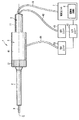
本発明の第1の実施形態について図1乃至図12を参照して説明する。図1は、本実施形態の超音波処置装置1を示す図である。なお、本実施形態の超音波処置装置1は、超音波振動によって発生したキャビテーションにより、生体組織を選択的に破砕及び切除し、切除された生体組織を吸引する超音波吸引装置である。
(First embodiment)
A first embodiment of the present invention will be described with reference to FIGS. FIG. 1 is a diagram showing an ultrasonic treatment apparatus 1 of the present embodiment. In addition, the ultrasonic treatment apparatus 1 of this embodiment is an ultrasonic suction apparatus that selectively crushes and excises living tissue by cavitation generated by ultrasonic vibration and sucks the excised living tissue.

図1に示すように、超音波処置装置1は、振動子ユニット2と、超音波プローブ(プローブユニット)3と、シース(シースユニット)4と、ハンドルユニット5とを備える。   As shown in FIG. 1, the ultrasonic treatment apparatus 1 includes a transducer unit 2, an ultrasonic probe (probe unit) 3, a sheath (sheath unit) 4, and a handle unit 5.

振動子ユニット2は、振動子ケース11を備える。振動子ケース11の基端には、ケーブル6の一端が接続されている。ケーブル6の他端は、電源ユニット7に接続されている。電源ユニット7は、超音波制御部8を備える。電源ユニット7には、フットスイッチ等の入力ユニット10が接続されている。   The vibrator unit 2 includes a vibrator case 11. One end of the cable 6 is connected to the base end of the vibrator case 11. The other end of the cable 6 is connected to the power supply unit 7. The power supply unit 7 includes an ultrasonic control unit 8. An input unit 10 such as a foot switch is connected to the power supply unit 7.

図2は、振動子ユニット2の構成を示す図である。図2に示すように、振動子ケース11の内部には、電流を超音波振動に変換する圧電素子を備える超音波振動子12が設けられている。超音波振動子12には、電気信号線13A,13Bの一端が接続されている。電気信号線13A,13Bは、ケーブル6の内部を通って、他端が電源ユニット7の超音波制御部8に接続されている。超音波制御部8から電気信号線13A,13Bを介して超音波振動子12に電流を供給することにより、超音波振動子12で超音波振動が発生する。超音波振動子12の先端方向側には、超音波振動の振幅を拡大するホーン15が連結されている。ホーン15は、振動子ケース11に取付けられている。超音波振動子12及びホーン15には、長手軸Cを中心に空間部19が形成されている。また、ホーン15の内周面の先端部には、雌ネジ部16が形成されている。   FIG. 2 is a diagram illustrating a configuration of the vibrator unit 2. As shown in FIG. 2, an ultrasonic transducer 12 including a piezoelectric element that converts current into ultrasonic vibration is provided inside the transducer case 11. One end of electric signal lines 13A and 13B is connected to the ultrasonic transducer 12. The electric signal lines 13 </ b> A and 13 </ b> B pass through the inside of the cable 6 and the other end is connected to the ultrasonic control unit 8 of the power supply unit 7. By supplying a current from the ultrasonic control unit 8 to the ultrasonic vibrator 12 via the electric signal lines 13A and 13B, ultrasonic vibration is generated in the ultrasonic vibrator 12. A horn 15 that expands the amplitude of the ultrasonic vibration is connected to the tip side of the ultrasonic vibrator 12. The horn 15 is attached to the vibrator case 11. A space portion 19 is formed around the longitudinal axis C in the ultrasonic vibrator 12 and the horn 15. A female screw portion 16 is formed at the tip of the inner peripheral surface of the horn 15.

図3及び図4は、超音波プローブ3の構成を示す図である。図3及び図4に示すように、超音波プローブ3は、プローブ本体21と、筒状部31と、チューブ41とを備える。   3 and 4 are diagrams showing the configuration of the ultrasonic probe 3. As shown in FIGS. 3 and 4, the ultrasonic probe 3 includes a probe main body 21, a cylindrical portion 31, and a tube 41.

プローブ本体21は、長手軸Cに沿って延設されている。プローブ本体21は、長手軸Cに沿って設けられる外周部30を備える。プローブ本体21の基端方向側の部位には、基端側接続部22がプローブ本体21と一体に設けられている。また、プローブ本体21の先端方向側の部位には、先端側接続部23がプローブ本体21と一体に設けられている。   The probe body 21 extends along the longitudinal axis C. The probe main body 21 includes an outer peripheral portion 30 provided along the longitudinal axis C. A proximal end side connecting portion 22 is provided integrally with the probe main body 21 at a proximal end side portion of the probe main body 21. In addition, a distal end side connection portion 23 is provided integrally with the probe main body 21 at a position on the distal end side of the probe main body 21.

図5は、プローブ本体21の長手軸Cに垂直な断面を示す図である。図4及び図5に示すように、プローブ本体21は、溝状部24を長手軸Cに沿って規定する溝規定面25を備える。溝状部24は、プローブ本体21の基端から先端まで延設されている。溝状部24は、長手軸Cに垂直な第1の垂直方向(図5の矢印X1の方向)から第1の垂直方向とは反対方向である第2の垂直方向(図5の矢印X2の方向)に向かって凹んでいる。溝状部24は、長手軸Cより第2の垂直方向側の部位まで第2の垂直方向に向かって凹んでいる。   FIG. 5 is a view showing a cross section perpendicular to the longitudinal axis C of the probe main body 21. As shown in FIGS. 4 and 5, the probe main body 21 includes a groove defining surface 25 that defines the groove-like portion 24 along the longitudinal axis C. The groove portion 24 extends from the proximal end to the distal end of the probe main body 21. The groove-like portion 24 has a second vertical direction (indicated by an arrow X2 in FIG. 5) that is opposite to the first vertical direction from a first vertical direction (in the direction indicated by the arrow X1 in FIG. 5) perpendicular to the longitudinal axis C. Dent). The groove-like portion 24 is recessed in the second vertical direction from the longitudinal axis C to a portion on the second vertical direction side.

すなわち、垂直な第1の垂直方向から第2の垂直方向に向かって空洞部である溝状部24が延設されている。そして、空洞規定面である溝規定面25の第1の垂直方向側の端部は、プローブ本体21の外周部30に連続している。また、溝規定面25は、長手軸Cに垂直な断面において円弧状に形成される曲面である。   That is, the groove-like portion 24 that is a hollow portion extends from the vertical first vertical direction to the second vertical direction. The end portion on the first vertical direction side of the groove defining surface 25 that is the cavity defining surface is continuous with the outer peripheral portion 30 of the probe main body 21. The groove defining surface 25 is a curved surface formed in an arc shape in a cross section perpendicular to the longitudinal axis C.

図4に示すように、基端側接続部22の外周部30には、雄ネジ部26が設けられている。雄ネジ部26がホーン15の雌ネジ部16と螺合することにより、ホーン15の先端方向側に超音波プローブ3のプローブ本体21が取付けられる。また、基端側接続部22には、溝状部24の基端と連通する基端側溝部27が設けられている。基端側溝部27は、溝状部24と同様に、第1の垂直方向から第2の垂直方向に向かって凹んでいる。   As shown in FIG. 4, a male screw portion 26 is provided on the outer peripheral portion 30 of the proximal end side connection portion 22. When the male screw portion 26 is screwed with the female screw portion 16 of the horn 15, the probe main body 21 of the ultrasonic probe 3 is attached to the distal direction side of the horn 15. In addition, the base end side connecting portion 22 is provided with a base end side groove portion 27 communicating with the base end of the groove-like portion 24. Similar to the groove-shaped portion 24, the proximal-side groove portion 27 is recessed from the first vertical direction toward the second vertical direction.

図6は、ホーン15と超音波プローブ3との間の構成を示す図である。図3及び図6に示すように、ホーン15にプローブ本体21を取付けた状態では、基端側接続部22はホーン15の内周側に位置している。このため、長手軸Cに平行な方向について、ホーン15の先端の位置と溝規定面25の基端の位置とは、略一致している。したがって、ホーン15にプローブ本体21を取付けた状態では、ホーン15の先端(溝規定面25の基端)から、溝状部24が長手軸Cに沿って延設される。   FIG. 6 is a diagram showing a configuration between the horn 15 and the ultrasonic probe 3. As shown in FIGS. 3 and 6, in a state where the probe main body 21 is attached to the horn 15, the proximal end side connecting portion 22 is located on the inner peripheral side of the horn 15. For this reason, in the direction parallel to the longitudinal axis C, the position of the tip of the horn 15 and the position of the base end of the groove defining surface 25 are substantially the same. Therefore, in a state where the probe main body 21 is attached to the horn 15, the groove-like portion 24 extends along the longitudinal axis C from the tip of the horn 15 (the base end of the groove defining surface 25).

図4に示すように、先端側接続部23には、溝状部24の先端と連通する先端側溝部28が設けられている。先端側溝部28は、溝状部24と同様に、第1の垂直方向から第2の垂直方向に向かって凹んでいる。また、先端側接続部23の内周部には、雌ネジ部29が設けられている。   As shown in FIG. 4, the distal end side connecting portion 23 is provided with a distal end side groove portion 28 that communicates with the distal end of the groove-shaped portion 24. Similar to the groove-shaped portion 24, the distal-end-side groove 28 is recessed from the first vertical direction to the second vertical direction. A female screw portion 29 is provided on the inner peripheral portion of the distal end side connection portion 23.

図3及び図4に示すように、筒状部31は、プローブ本体21の先端方向側に連結される。筒状部31の外周部の基端部には、雄ネジ部32が設けられている。雄ネジ部32が先端側接続部23の雌ネジ部29と螺合することにより、筒状部31がプローブ本体21に連結される。   As shown in FIGS. 3 and 4, the cylindrical portion 31 is connected to the distal direction side of the probe main body 21. A male screw portion 32 is provided at the proximal end portion of the outer peripheral portion of the cylindrical portion 31. The cylindrical portion 31 is coupled to the probe main body 21 by the male screw portion 32 being screwed with the female screw portion 29 of the distal end side connection portion 23.

図7は、プローブ本体21の筒状部31との間の構成を示す図である。図3及び図7に示すように、プローブ本体21に筒状部31を連結した状態では、先端側接続部23は、筒状部31の外周側に位置している。このため、長手軸Cに平行な方向について、筒状部31の基端の位置と溝規定面25の先端の位置とは、略一致している。したがって、プローブ本体21に筒状部31を連結した状態では、筒状部31の基端(溝規定面25の先端)まで、溝状部24が長手軸Cに沿って延設される。また、プローブ本体21に筒状部31を連結した状態では、筒状部31の内部が溝状部24と連通している。   FIG. 7 is a diagram illustrating a configuration between the probe main body 21 and the cylindrical portion 31. As shown in FIGS. 3 and 7, in a state where the tubular portion 31 is coupled to the probe main body 21, the distal end side connecting portion 23 is located on the outer peripheral side of the tubular portion 31. For this reason, in the direction parallel to the longitudinal axis C, the position of the proximal end of the cylindrical portion 31 and the position of the distal end of the groove defining surface 25 are substantially the same. Therefore, in a state where the cylindrical portion 31 is connected to the probe main body 21, the groove-like portion 24 extends along the longitudinal axis C up to the proximal end of the cylindrical portion 31 (the tip of the groove defining surface 25). Further, in the state where the tubular portion 31 is connected to the probe main body 21, the inside of the tubular portion 31 communicates with the groove-shaped portion 24.

以上のように、ホーン15にプローブ本体21が取付けられ、かつ、プローブ本体21に筒状部31が連結されることにより、超音波振動子12で発生した超音波振動が、ホーン15、プローブ本体21を介して、筒状部31の先端まで伝達される。すなわち、超音波プローブ3の基端から先端へ超音波振動が伝達される。この際、ホーン15、プローブ本体21、筒状部31により超音波振動を伝達する振動伝達部20が形成されている。なお、超音波振動は、振動の伝達方向と振動方向が一致する縦振動である。   As described above, when the probe main body 21 is attached to the horn 15 and the cylindrical portion 31 is connected to the probe main body 21, the ultrasonic vibration generated in the ultrasonic vibrator 12 is generated by the horn 15, the probe main body. It is transmitted to the tip of the cylindrical part 31 via 21. That is, ultrasonic vibration is transmitted from the proximal end to the distal end of the ultrasonic probe 3. At this time, the horn 15, the probe main body 21, and the cylindrical portion 31 form a vibration transmitting portion 20 that transmits ultrasonic vibration. The ultrasonic vibration is longitudinal vibration in which the vibration transmission direction and the vibration direction coincide with each other.

ホーン15にプローブ本体21が取付けられ、かつ、プローブ本体21に筒状部31が連結された状態では、ホーン15の先端(溝規定面25の基端)が、超音波振動の第1の腹位置A1となる。また、筒状部31の基端(溝規定面25の先端)が、第1の腹位置A1とは異なる超音波振動の第2の腹位置A2となる。ホーン15にプローブ本体21が取付けられ、かつ、プローブ本体21に筒状部31が連結された状態で、溝状部24は、ホーン15の先端から筒状部31の基端まで延設されている。したがって、ホーン15にプローブ本体21が取付けられ、かつ、プローブ本体21に筒状部31が連結された状態では、第1の腹位置A1から第2の腹位置A2まで長手軸Cに沿って溝状部24が、溝規定面25により規定されている。   In a state in which the probe main body 21 is attached to the horn 15 and the cylindrical portion 31 is connected to the probe main body 21, the tip of the horn 15 (the base end of the groove defining surface 25) is the first antinode of the ultrasonic vibration. Position A1. Moreover, the base end (tip of the groove defining surface 25) of the cylindrical portion 31 is a second antinode vibration A2 that is different from the first antinode position A1. In a state where the probe main body 21 is attached to the horn 15 and the cylindrical portion 31 is connected to the probe main body 21, the groove-shaped portion 24 extends from the distal end of the horn 15 to the proximal end of the cylindrical portion 31. Yes. Therefore, in a state where the probe main body 21 is attached to the horn 15 and the cylindrical portion 31 is connected to the probe main body 21, a groove is formed along the longitudinal axis C from the first antinode position A1 to the second antinode position A2. The shaped portion 24 is defined by the groove defining surface 25.

ここで、第1の腹位置A1では、超音波振動の伝達方向及び振動方向(長手軸C)に垂直な振動伝達部20の断面形状が変化する。すなわち、振動伝達部20の長手軸Cに垂直な断面形状が、長手軸Cを中心として点対称な筒状から長手軸Cを中心として点対称でない凹状へ、第1の腹位置A1で変化する。同様に、第2の腹位置A2では、超音波振動の伝達方向及び振動方向(長手軸C)に垂直な振動伝達部20の断面形状が変化する。すなわち、振動伝達部20の長手軸Cに垂直な断面形状が、長手軸Cを中心として点対称でない凹状から長手軸Cを中心として点対称な筒状へ、第2の腹位置A2で変化する。   Here, at the first antinode position A1, the ultrasonic vibration transmission direction and the cross-sectional shape of the vibration transmission unit 20 perpendicular to the vibration direction (longitudinal axis C) change. That is, the cross-sectional shape perpendicular to the longitudinal axis C of the vibration transmitting portion 20 changes from the cylindrical shape that is point-symmetric about the longitudinal axis C to the concave shape that is not point-symmetrical about the longitudinal axis C at the first antinode position A1. . Similarly, at the second antinode position A2, the ultrasonic vibration transmission direction and the cross-sectional shape of the vibration transmission unit 20 perpendicular to the vibration direction (longitudinal axis C) change. That is, the cross-sectional shape perpendicular to the longitudinal axis C of the vibration transmitting portion 20 changes from a concave shape that is not point-symmetrical about the longitudinal axis C to a cylindrical shape that is point-symmetrical about the longitudinal axis C at the second antinode position A2. .

また、ホーン15にプローブ本体21が取付けられ、かつ、プローブ本体21に筒状部31が連結された状態では、筒状部31の先端が第1の腹位置A1及び第2の腹位置A2とは異なる超音波振動の第3の腹位置A3となる。筒状部31(超音波プローブ3)の先端に超音波振動が伝達されることにより、キャビテーションを発生する。キャビテーションにより、肝細胞等の弾力性の低い生体組織が選択的に破砕及び乳化される。この際、血管等の弾力性の高い生体組織は、キャビテーションにより破砕されない。   When the probe main body 21 is attached to the horn 15 and the cylindrical portion 31 is connected to the probe main body 21, the tip of the cylindrical portion 31 is connected to the first antinode position A1 and the second antinode position A2. Becomes the third antinode vibration A3 of different ultrasonic vibrations. Cavitation is generated by transmitting ultrasonic vibration to the tip of the cylindrical portion 31 (ultrasonic probe 3). Cavitation selectively crushes and emulsifies biological tissue with low elasticity such as hepatocytes. At this time, a highly elastic living tissue such as a blood vessel is not crushed by cavitation.

なお、プローブ本体21及び筒状部31の外周部には、段差が設けられていることが好ましい。これにより、超音波振動の振幅が拡大される。   In addition, it is preferable that the outer peripheral part of the probe main body 21 and the cylindrical part 31 is provided with the level | step difference. Thereby, the amplitude of ultrasonic vibration is expanded.

図3及び図4に示すように、チューブ41は、溝状部24の内部を長手軸Cに沿って延設されている。チューブ41は耐熱性の樹脂から形成されている。図7に示すように、筒状部31は、チューブ41の内部と連通する吸引通路33を規定する通路規定面35を備える。通路規定面35の基端にチューブ41の先端が接続されている。チューブ41の先端は、例えば接着材34により筒状部31に固定され、通路規定面35に接続されている。なお、通路規定面35へのチューブ41の先端の接続は、接着剤34以外の手法により行われてもよい。例えば、チューブ41の外周部に耐熱性のゴムライニングにより弾性部材を取付け、弾性部材によりチューブ41の先端を筒状部31に固定し、通路規定面35に接続してもよい。また、筒状部31の内周部に設けられた雌ネジ部とチューブ41の外周部に設けられた雄ネジ部とを螺合することにより、チューブ41の先端を筒状部31に固定し、通路規定面35に接続してもよい。   As shown in FIGS. 3 and 4, the tube 41 extends along the longitudinal axis C inside the groove-like portion 24. The tube 41 is formed from a heat resistant resin. As shown in FIG. 7, the cylindrical portion 31 includes a passage defining surface 35 that defines a suction passage 33 that communicates with the inside of the tube 41. The distal end of the tube 41 is connected to the proximal end of the passage defining surface 35. The distal end of the tube 41 is fixed to the cylindrical portion 31 with, for example, an adhesive material 34 and connected to the passage defining surface 35. Note that the connection of the tip of the tube 41 to the passage defining surface 35 may be performed by a method other than the adhesive 34. For example, an elastic member may be attached to the outer peripheral portion of the tube 41 with a heat-resistant rubber lining, and the tip of the tube 41 may be fixed to the cylindrical portion 31 with the elastic member and connected to the passage defining surface 35. Further, the tip of the tube 41 is fixed to the cylindrical portion 31 by screwing the female screw portion provided on the inner peripheral portion of the cylindrical portion 31 and the male screw portion provided on the outer peripheral portion of the tube 41. Alternatively, it may be connected to the passage defining surface 35.

ホーン15にプローブ本体21が取付けられ、かつ、プローブ本体21に筒状部31が連結された状態では、筒状部31の基端と筒状部31の先端との中間位置に超音波振動の第1の節位置(節位置)B1が位置している。この際、通路規定面35は、第1の節位置B1から第3の腹位置A3まで長手軸Cに沿って設けられている。すなわち、通路規定面35の基端が第1の節位置B1となり、通路規定面35の先端が第3の腹位置A3となる。前述のように、チューブ41の先端は、通路規定面35の基端に接続されている。したがって、チューブ41の先端は、第1の節位置B1で通路規定面35に接続されている。   In a state where the probe main body 21 is attached to the horn 15 and the cylindrical portion 31 is connected to the probe main body 21, ultrasonic vibration is generated at an intermediate position between the proximal end of the cylindrical portion 31 and the distal end of the cylindrical portion 31. A first node position (node position) B1 is located. At this time, the passage defining surface 35 is provided along the longitudinal axis C from the first node position B1 to the third antinode position A3. That is, the base end of the passage defining surface 35 is the first node position B1, and the distal end of the passage defining surface 35 is the third antinode position A3. As described above, the distal end of the tube 41 is connected to the proximal end of the passage defining surface 35. Therefore, the tip of the tube 41 is connected to the passage defining surface 35 at the first node position B1.

また、筒状部31は、チューブ41が挿通される挿通孔36を規定する孔規定面37を備える。挿通孔36の径は、チューブ41の外径より十分に大きく形成されている。ホーン15にプローブ本体21が取付けられ、かつ、プローブ本体21に筒状部31が連結された状態では、孔規定面37は、第2の腹位置A2から第1の節位置B1まで長手軸Cに沿って設けられている。すなわち、孔規定面37の基端が第2の腹位置A2となり、孔規定面37の先端が第1の節位置B1となる。孔規定面37の先端方向側には、通路規定面35が連続している。   The cylindrical portion 31 includes a hole defining surface 37 that defines an insertion hole 36 through which the tube 41 is inserted. The diameter of the insertion hole 36 is formed sufficiently larger than the outer diameter of the tube 41. When the probe main body 21 is attached to the horn 15 and the cylindrical portion 31 is connected to the probe main body 21, the hole defining surface 37 has a longitudinal axis C from the second antinode position A2 to the first node position B1. It is provided along. That is, the base end of the hole defining surface 37 is the second antinode position A2, and the tip of the hole defining surface 37 is the first node position B1. On the tip direction side of the hole defining surface 37, the passage defining surface 35 is continuous.

吸引通路33の長手軸Cに垂直な断面積は、挿通孔36の長手軸Cに垂直な断面積より小さい状態に規定されている。また、吸引通路33の長手軸Cに垂直な断面積は、長手軸Cに垂直な断面においてチューブ41の内周部で囲まれた部分の面積より小さいことが好ましい。   A cross-sectional area perpendicular to the longitudinal axis C of the suction passage 33 is defined to be smaller than a cross-sectional area perpendicular to the longitudinal axis C of the insertion hole 36. The cross-sectional area perpendicular to the longitudinal axis C of the suction passage 33 is preferably smaller than the area of the section surrounded by the inner periphery of the tube 41 in the cross-section perpendicular to the longitudinal axis C.

図6に示すように、チューブ41の基端は、ホーン15の先端より基端方向側でホーン15に接続されている。ホーン15にプローブ本体21が取付けられ、かつ、プローブ本体21に筒状部31が連結された状態では、チューブ41の基端のホーン15への接続位置は第2の節位置B2となる。ホーン15の先端は、超音波振動の第1の腹位置A1となる。したがって、第2の節位置B2は、第1の腹位置A1より基端方向側に位置している。なお、チューブ41の基端のホーン15への接続は、通路規定面35へのチューブ41の先端の接続と同様にして行われる。   As shown in FIG. 6, the proximal end of the tube 41 is connected to the horn 15 on the proximal direction side from the distal end of the horn 15. In a state where the probe main body 21 is attached to the horn 15 and the tubular portion 31 is coupled to the probe main body 21, the connection position of the base end of the tube 41 to the horn 15 is the second node position B2. The tip of the horn 15 is the first antinode position A1 for ultrasonic vibration. Therefore, the second node position B2 is located on the proximal direction side from the first antinode position A1. The connection of the proximal end of the tube 41 to the horn 15 is performed in the same manner as the connection of the distal end of the tube 41 to the passage defining surface 35.

チューブ41の基端をホーン15へ接続することにより、チューブ41の内部は超音波振動子12及びホーン15の内部の空間部19に連通する。図2に示すように、空間部19には、吸引チューブ42の一端が接続されている。図1に示すように、吸引チューブ42は、振動子ケース11の外部に延出され、他端が吸引ユニット43に接続されている。吸引ユニット43は、入力ユニット10に接続されている。キャビテーションにより切除された生体組織を吸引する際には、入力ユニット10での入力等により吸引ユニット43を駆動する。吸引ユニット43を駆動することにより、切除された生体組織が吸引通路33に吸引される。そして、チューブ41の内部、空間部19、吸引チューブ42の内部を順に通って、生体組織が吸引ユニット43まで吸引される。   By connecting the base end of the tube 41 to the horn 15, the inside of the tube 41 communicates with the ultrasonic transducer 12 and the space 19 inside the horn 15. As shown in FIG. 2, one end of a suction tube 42 is connected to the space 19. As shown in FIG. 1, the suction tube 42 extends to the outside of the transducer case 11, and the other end is connected to the suction unit 43. The suction unit 43 is connected to the input unit 10. When aspirating the living tissue excised by cavitation, the aspiration unit 43 is driven by an input from the input unit 10 or the like. By driving the suction unit 43, the excised living tissue is sucked into the suction passage 33. Then, the living tissue is sucked up to the suction unit 43 through the inside of the tube 41, the space 19, and the inside of the suction tube 42 in order.

なお、チューブ41は先端が筒状部31に固定され、基端がホーン15に固定されている。このため、チューブ41は、プローブ本体21に固定してもよく、プローブ本体21に固定しなくてもよい。チューブ41をプローブ本体21に固定する場合は、第1の節位置B1及び第2の節位置B2とは異なる節位置で、プローブ本体21へ固定される。チューブ41のプローブ本体21への固定は、例えば接着剤を介して行われる。また、チューブ41の外周部に耐熱性のゴムライニングにより弾性部材を取付け、弾性部材によりチューブ41をプローブ本体21に固定してもよい。また、溝規定面25に耐熱性のゴムライニングにより弾性部材を取付け、弾性部材によりチューブ41をプローブ本体21に固定してもよい。   The tube 41 has a distal end fixed to the cylindrical portion 31 and a proximal end fixed to the horn 15. For this reason, the tube 41 may be fixed to the probe main body 21 or may not be fixed to the probe main body 21. When the tube 41 is fixed to the probe main body 21, it is fixed to the probe main body 21 at a node position different from the first node position B1 and the second node position B2. The tube 41 is fixed to the probe main body 21 through, for example, an adhesive. Alternatively, an elastic member may be attached to the outer periphery of the tube 41 with a heat-resistant rubber lining, and the tube 41 may be fixed to the probe body 21 with the elastic member. Alternatively, an elastic member may be attached to the groove defining surface 25 with a heat-resistant rubber lining, and the tube 41 may be fixed to the probe body 21 with the elastic member.

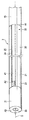
ここで、超音波プローブ3の製造方法について説明する。超音波プローブ3を製造する際は、まず、プローブ本体21を形成する。図8は、プローブ本体21のある製造方法を示す図である。図8に示すように、プローブ本体21、基端側接続部22及び先端側接続部23を形成する際は、平板部材47を曲げ加工する。これにより、溝状部24、基端側溝部27及び先端側溝部28が形成される。そして、切削加工等により、基端側接続部22及び先端側接続部23を備えるプローブ本体21の形状が形成される。   Here, a method for manufacturing the ultrasonic probe 3 will be described. When manufacturing the ultrasonic probe 3, first, the probe body 21 is formed. FIG. 8 is a diagram showing a method for manufacturing the probe main body 21. As shown in FIG. 8, when the probe main body 21, the base end side connection portion 22, and the tip end side connection portion 23 are formed, the flat plate member 47 is bent. Thereby, the groove-shaped part 24, the base end side groove part 27, and the front end side groove part 28 are formed. And the shape of the probe main body 21 provided with the base end side connection part 22 and the front end side connection part 23 is formed by cutting etc. FIG.

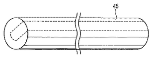
図9Aは、プローブ本体21、基端側接続部22及び先端側接続部23の別のある製造方法を示す図である。図9Aに示すように、プローブ本体21を形成する際は、柱状部材45をフライス(fraise)加工することにより、図9Aの点線で示す部分を切除する。これにより、溝状部24、基端側溝部27及び先端側溝部28が形成される。また、プローブ本体21、基端側接続部22及び先端側接続部23は、鍛造(forging)により形成してもよい。   FIG. 9A is a diagram illustrating another manufacturing method of the probe main body 21, the proximal end side connection portion 22, and the distal end side connection portion 23. As shown in FIG. 9A, when the probe main body 21 is formed, the columnar member 45 is milled to cut out a portion indicated by a dotted line in FIG. 9A. Thereby, the groove-shaped part 24, the base end side groove part 27, and the front end side groove part 28 are formed. Further, the probe main body 21, the proximal end side connection portion 22, and the distal end side connection portion 23 may be formed by forging.

ここで、図8に示す方法でプローブ本体21を製造する場合、溝規定面25は、長手軸Cに垂直な断面において円弧状に形成される曲面であることが好ましい。また、図9Aに示す方法でプローブ本体21を製造する場合は、図9Bに示すように、溝規定面25は、平面部44と、平面部44の第2の垂直方向側に設けられる曲面部46とを備えることが好ましい。この場合、平面部44は、長手軸Cに平行、かつ、第1の垂直方向から第2の垂直方向に向かって延設されている。また、曲面部46は、長手軸Cに垂直な断面において円弧状に形成されている。以上のように溝規定面25を形成することにより、容易にフライス加工を行うことが可能となる。このため、さらに容易かつ低コストでプローブ本体21が製造される。   Here, when the probe main body 21 is manufactured by the method shown in FIG. 8, the groove defining surface 25 is preferably a curved surface formed in an arc shape in a cross section perpendicular to the longitudinal axis C. 9A, when the probe main body 21 is manufactured by the method shown in FIG. 9A, the groove defining surface 25 includes a flat portion 44 and a curved portion provided on the second vertical direction side of the flat portion 44, as shown in FIG. 9B. 46 is preferable. In this case, the plane portion 44 is parallel to the longitudinal axis C and extends from the first vertical direction to the second vertical direction. The curved surface portion 46 is formed in an arc shape in a cross section perpendicular to the longitudinal axis C. By forming the groove defining surface 25 as described above, milling can be easily performed. For this reason, the probe main body 21 is manufactured more easily and at low cost.

前述のように、基端側接続部22及び先端側接続部23を備えるプローブ本体21を形成した後、プローブ本体21の先端方向側に筒状部31を連結する。そして、溝状部24の内部に長手軸Cに沿ってチューブ41が配置される。そして、チューブ41の先端を筒状部31に接続する。前述のように、溝状部24は、長手軸Cより第2の垂直方向側の部位まで第2の垂直方向に向かって凹んでいる。すなわち、空洞部である溝状部24は、長手軸Cより第2の垂直方向側の部位まで第2の垂直方向に向かって延設されている。このため、溝状部24の内部に配置されるチューブ41の先端を筒状部31に容易に接続可能である。以上のようにして、超音波プローブ3が形成される。   As described above, after forming the probe main body 21 including the proximal end side connection portion 22 and the distal end side connection portion 23, the cylindrical portion 31 is connected to the distal end side of the probe main body 21. And the tube 41 is arrange | positioned along the longitudinal axis C inside the groove-shaped part 24. FIG. Then, the tip of the tube 41 is connected to the cylindrical portion 31. As described above, the groove-like portion 24 is recessed in the second vertical direction from the longitudinal axis C to the second vertical side portion. That is, the groove-like portion 24 that is a hollow portion extends in the second vertical direction from the longitudinal axis C to a portion on the second vertical direction side. For this reason, the tip of the tube 41 disposed inside the groove-like portion 24 can be easily connected to the cylindrical portion 31. The ultrasonic probe 3 is formed as described above.

ここで、比較例として図10に示すように、長手軸Cに沿った寸法全体が筒状に形成される超音波プローブ3Aを考える。超音波プローブ3Aは、柱状部材(図示しない)を孔開け加工することにより形成される。ここで、超音波プローブ3Aの材料となる柱状部材は、長手軸Cに沿った寸法が長く、長手軸Cに垂直な方向の寸法は小さい。このような細長い柱状部材の孔開け加工は、専用のドリルを用いて長時間要して行われ、コストも増加する。   Here, as a comparative example, consider an ultrasonic probe 3A in which the entire dimension along the longitudinal axis C is formed in a cylindrical shape as shown in FIG. The ultrasonic probe 3A is formed by drilling a columnar member (not shown). Here, the columnar member used as the material of the ultrasonic probe 3A has a long dimension along the longitudinal axis C and a small dimension in a direction perpendicular to the longitudinal axis C. Such a long and narrow columnar member is perforated for a long time using a dedicated drill, which increases costs.

一方、本実施形態の超音波プローブ3では、溝状部24が形成されたプローブ本体21が、超音波プローブ3の長手軸Cに沿った寸法の大部分を占めている。上述のように、プローブ本体21を形成することは、柱状部材への孔開け加工に比べ、短時間かつ低コストで行われる。また、孔開け加工が必要な筒状部31の長手軸Cに沿った寸法は小さい。このため、超音波プローブ3Aを形成する場合に比べ、孔開け加工に要する時間は短い。したがって、効率よく、低コストで超音波プローブ3が製造される。   On the other hand, in the ultrasonic probe 3 of the present embodiment, the probe main body 21 in which the groove-like portion 24 is formed occupies most of the dimension along the longitudinal axis C of the ultrasonic probe 3. As described above, the formation of the probe main body 21 is performed in a short time and at a low cost as compared with the drilling process for the columnar member. Moreover, the dimension along the longitudinal axis C of the cylindrical part 31 which needs to be perforated is small. For this reason, compared with the case where the ultrasonic probe 3A is formed, the time required for drilling is shorter. Therefore, the ultrasonic probe 3 is manufactured efficiently and at a low cost.

図1に示すように、シース4には、超音波プローブ3が挿通されている。図11は、シース4に超音波プローブ3が挿通された状態を示す図である。図11に示すように、シース4に超音波プローブ3が挿通された状態では、超音波プローブ3の外周部とシース4の内周部との間に、送水経路48が形成されている。すなわち、超音波プローブ3の外周部及びシース4の内周部により、送水経路48が規定されている。   As shown in FIG. 1, the ultrasonic probe 3 is inserted through the sheath 4. FIG. 11 is a view showing a state in which the ultrasonic probe 3 is inserted through the sheath 4. As shown in FIG. 11, in a state where the ultrasonic probe 3 is inserted through the sheath 4, a water supply path 48 is formed between the outer peripheral portion of the ultrasonic probe 3 and the inner peripheral portion of the sheath 4. That is, the water supply path 48 is defined by the outer peripheral portion of the ultrasonic probe 3 and the inner peripheral portion of the sheath 4.

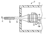
図12は、シース4と振動子ケース11との連結部の構成を概略的に示す図である。シース4の基端部には、筒状の中継部材49の先端部が取付けられている。シース4は、中継部材49に対して長手軸C回りに回転可能である。中継部材49の基端部には、振動子ケース11の先端部が取付けられている。   FIG. 12 is a diagram schematically showing the configuration of the connecting portion between the sheath 4 and the transducer case 11. A distal end portion of a cylindrical relay member 49 is attached to the proximal end portion of the sheath 4. The sheath 4 can rotate around the longitudinal axis C with respect to the relay member 49. The distal end portion of the vibrator case 11 is attached to the proximal end portion of the relay member 49.

超音波プローブ3とシース4との間に形成される送水経路48は、振動子ケース11の先端面まで延設されている。中継部材49の内部には、送水チューブ51の一端が接続されている。図1に示すように、送水チューブ51は、ハンドルユニット5の外部に延出され、他端が送水ユニット53に接続されている。送水ユニット53は、入力ユニット10に接続されている。入力ユニット10での入力等により送水ユニット53を駆動することにより、送水チューブ51の内部、送水経路48を順に水(液体)が通る。そして、シース4の先端の超音波プローブ3との間の隙間から、生体組織等への送水が行われる。送水により、出血箇所の確認、体腔内の洗浄等が行われる。また、超音波吸引においては、送水ユニット53から処置位置の近傍に生理食塩水等の液体が送水される。   A water supply path 48 formed between the ultrasonic probe 3 and the sheath 4 extends to the distal end surface of the transducer case 11. One end of the water supply tube 51 is connected to the inside of the relay member 49. As shown in FIG. 1, the water supply tube 51 extends outside the handle unit 5, and the other end is connected to the water supply unit 53. The water supply unit 53 is connected to the input unit 10. By driving the water supply unit 53 by input or the like at the input unit 10, water (liquid) sequentially passes through the water supply tube 51 and the water supply path 48. Then, water is supplied to the living tissue or the like from the gap between the ultrasonic probe 3 at the tip of the sheath 4. Confirmation of bleeding site, cleaning of body cavity, etc. are performed by water supply. In ultrasonic suction, a liquid such as physiological saline is supplied from the water supply unit 53 to the vicinity of the treatment position.

図1に示すように、ハンドルユニット5は、筒状ケース61を備える。筒状ケース61は、振動子ケース11に取付けられる。また、筒状ケース61の先端方向側には、回転操作ノブ67が連結されている。回転操作ノブ67は、筒状ケース61に対して長手軸C回りに回転可能である。回転操作ノブ67の内周側には、シース4が取付けられている。回転操作ノブ67を回転することにより、超音波プローブ3及びシース4が回転操作ノブ67と一体に、長手軸C回りに回転する。   As shown in FIG. 1, the handle unit 5 includes a cylindrical case 61. The cylindrical case 61 is attached to the vibrator case 11. A rotation operation knob 67 is connected to the distal direction side of the cylindrical case 61. The rotation operation knob 67 can rotate about the longitudinal axis C with respect to the cylindrical case 61. The sheath 4 is attached to the inner peripheral side of the rotation operation knob 67. By rotating the rotation operation knob 67, the ultrasonic probe 3 and the sheath 4 rotate around the longitudinal axis C together with the rotation operation knob 67.

次に、本実施形態の超音波処置装置1の作用について説明する。超音波処置装置1を用いて生体組織の超音波吸引を行う際には、超音波制御部8から電気信号線13A,13Bを介して超音波振動子12に電流を供給することにより、超音波振動子12で超音波振動が発生する。そして、振動伝達部20(超音波プローブ3)の基端から先端へ超音波振動が伝達される。   Next, the operation of the ultrasonic treatment apparatus 1 of the present embodiment will be described. When performing ultrasonic suction of a living tissue using the ultrasonic treatment apparatus 1, current is supplied from the ultrasonic control unit 8 to the ultrasonic transducer 12 via the electric signal lines 13A and 13B. Ultrasonic vibration is generated in the vibrator 12. Then, ultrasonic vibration is transmitted from the proximal end to the distal end of the vibration transmitting unit 20 (ultrasonic probe 3).

ここで、溝規定面25の基端(ホーン15の先端)に位置する第1の腹位置A1では、超音波振動の伝達方向及び振動方向(長手軸C)に垂直な振動伝達部20の断面形状が変化する。すなわち、振動伝達部20の長手軸Cに垂直な断面形状が、長手軸Cを中心として点対称な筒状から長手軸Cを中心として点対称でない凹状へ、第1の腹位置A1で変化する。超音波振動の伝達方向及び振動方向に垂直な振動伝達部20の断面形状が大きく変化する位置では、超音波振動が長手軸Cに垂直な方向への応力の影響を受け易い。応力の影響を受けることにより、超音波振動の振動モードが変化し、超音波プローブ3の先端まで超音波振動が適切に伝達されない。   Here, at the first antinode position A1 located at the base end (tip of the horn 15) of the groove defining surface 25, the cross section of the vibration transmitting portion 20 perpendicular to the ultrasonic vibration transmission direction and the vibration direction (longitudinal axis C). The shape changes. That is, the cross-sectional shape perpendicular to the longitudinal axis C of the vibration transmitting portion 20 changes from the cylindrical shape that is point-symmetric about the longitudinal axis C to the concave shape that is not point-symmetrical about the longitudinal axis C at the first antinode position A1. . The ultrasonic vibration is likely to be affected by stress in the direction perpendicular to the longitudinal axis C at the position where the ultrasonic vibration transmission direction and the cross-sectional shape of the vibration transmission unit 20 perpendicular to the vibration direction change greatly. Due to the influence of stress, the vibration mode of the ultrasonic vibration changes, and the ultrasonic vibration is not properly transmitted to the tip of the ultrasonic probe 3.

したがって、本実施形態では、第1の腹位置A1で超音波振動の伝達方向及び振動方向に垂直な振動伝達部20の断面形状が大きく変化する状態に、設定されている。第1の腹位置A1を含む超音波振動の腹位置では、振動による変位は最大となるが、長手軸Cに垂直な方向への応力はゼロとなる。したがって、超音波振動の伝達方向及び振動方向に垂直な振動伝達部20の断面形状が大きく変化する第1の腹位置A1で、超音波振動に応力が作用しない。したがって、振動モードが変化しない。   Therefore, in the present embodiment, the ultrasonic vibration transmission direction and the cross-sectional shape of the vibration transmission unit 20 perpendicular to the vibration direction at the first antinode position A1 are set to change greatly. At the antinode position of the ultrasonic vibration including the first antinode position A1, the displacement due to the vibration is maximum, but the stress in the direction perpendicular to the longitudinal axis C is zero. Accordingly, no stress acts on the ultrasonic vibration at the first antinode position A1 where the ultrasonic vibration transmission direction and the cross-sectional shape of the vibration transmission unit 20 perpendicular to the vibration direction change greatly. Therefore, the vibration mode does not change.

同様に、超音波プローブ3では、溝規定面25の先端(筒状部31の基端)に位置する第2の腹位置A2で、超音波振動の伝達方向及び振動方向に垂直な振動伝達部20の断面形状が大きく変化する状態に、設定されている。前述のように、第2の腹位置A2をでは、振動による変位は最大となるが、長手軸Cに垂直な方向への応力はゼロとなる。したがって、超音波振動の伝達方向及び振動方向に垂直な振動伝達部20の断面形状が大きく変化する第2の腹位置A2で、超音波振動に応力が作用しない。したがって、振動モードが変化しない。   Similarly, in the ultrasonic probe 3, at the second antinode position A2 located at the distal end of the groove defining surface 25 (the base end of the cylindrical portion 31), the ultrasonic vibration transmission direction and the vibration transmission portion perpendicular to the vibration direction. 20 is set so that its cross-sectional shape changes greatly. As described above, in the second antinode position A2, the displacement due to vibration becomes maximum, but the stress in the direction perpendicular to the longitudinal axis C becomes zero. Accordingly, no stress acts on the ultrasonic vibration at the second antinode position A2 where the ultrasonic vibration transmission direction and the cross-sectional shape of the vibration transmission unit 20 perpendicular to the vibration direction change greatly. Therefore, the vibration mode does not change.

以上のようにして、超音波振動の伝達方向及び振動方向に垂直な振動伝達部20の断面形状が大きく変化する位置を設けた場合も、超音波振動が長手軸Cに垂直な方向への応力の影響を受けない状態に設定されている。したがって、超音波プローブ3の先端まで、超音波振動が適切に伝達される。   As described above, the ultrasonic vibration is stressed in the direction perpendicular to the longitudinal axis C even when the transmission direction of the ultrasonic vibration and the position where the cross-sectional shape of the vibration transmission unit 20 perpendicular to the vibration direction changes greatly are provided. It is set to a state that is not affected by. Accordingly, ultrasonic vibration is appropriately transmitted to the tip of the ultrasonic probe 3.

また、超音波吸引においては、送水ユニット53から処置位置の近傍に生理食塩水等の液体が送水される。送水が行われた状態で筒状部31(超音波プローブ3)の先端に超音波振動が伝達されることにより、キャビテーションを発生する。キャビテーションにより、肝細胞等の弾力性の低い生体組織が選択的に破砕され、切除される。ここで、プローブ本体21の先端方向側に筒状部31が連結されることにより、超音波プローブ3の先端面が筒状に形成される。例えば、プローブ本体21の先端が超音波プローブの先端を形成する場合は、超音波プローブ3の先端面が凹状に形成される。先端面を筒状に形成することにより、先端面が凹状に形成される場合に比べ、超音波プローブ3の先端面の表面積が大きくなる。超音波プローブ3の先端面の表面積は大きくなるため、キャビテーションが効率的に発生し、効率よく、安全に生体組織の破砕及び切除が行われる。また、筒状部31(超音波プローブ3)の先端が超音波振動の第3の腹位置A3であるため、超音波振動が筒状部31の先端に伝達されることにより、キャビテーションがより効率的に発生する。   In ultrasonic suction, a liquid such as physiological saline is supplied from the water supply unit 53 to the vicinity of the treatment position. Cavitation is generated by transmitting ultrasonic vibration to the tip of the cylindrical portion 31 (ultrasonic probe 3) in a state where water is supplied. By cavitation, biological tissue with low elasticity such as hepatocytes is selectively crushed and excised. Here, the distal end surface of the ultrasonic probe 3 is formed in a cylindrical shape by connecting the tubular portion 31 to the distal direction side of the probe main body 21. For example, when the tip of the probe body 21 forms the tip of the ultrasonic probe, the tip surface of the ultrasonic probe 3 is formed in a concave shape. By forming the distal end surface in a cylindrical shape, the surface area of the distal end surface of the ultrasonic probe 3 becomes larger than when the distal end surface is formed in a concave shape. Since the surface area of the distal end surface of the ultrasonic probe 3 is increased, cavitation is efficiently generated, and biological tissue is efficiently and safely crushed and excised. In addition, since the tip of the cylindrical portion 31 (ultrasonic probe 3) is the third antinode position A3 of the ultrasonic vibration, the ultrasonic vibration is transmitted to the tip of the cylindrical portion 31, thereby making cavitation more efficient. Will occur.

また、チューブ41の先端は、第1の節位置B1で筒状部31の通路規定面35に接続されている。そして、チューブ41の基端は、第2の節位置B2でホーン15に接続されている。第1の節位置B1及び第2の節位置B2を含む超音波振動の節位置では、長手軸Cに垂直な方向への応力は最大となるが、振動による変位はゼロとなる。このため、振動伝達部20(超音波プローブ3)が超音波振動する際でも、チューブ41が筒状部31及びホーン15に強固に固定される。   The tip of the tube 41 is connected to the passage defining surface 35 of the cylindrical portion 31 at the first node position B1. The proximal end of the tube 41 is connected to the horn 15 at the second node position B2. At the ultrasonic vibration node positions including the first node position B1 and the second node position B2, the stress in the direction perpendicular to the longitudinal axis C is maximum, but the displacement due to vibration is zero. For this reason, the tube 41 is firmly fixed to the cylindrical portion 31 and the horn 15 even when the vibration transmitting portion 20 (ultrasonic probe 3) vibrates ultrasonically.

そして、キャビテーションにより生体組織が切除されると、切除された生体組織の吸引が行われる。吸引ユニット43を駆動することにより、切除された生体組織が吸引通路33に吸引される。そして、チューブ41の内部、空間部19、吸引チューブ42の内部を順に通って、生体組織が吸引ユニット43まで吸引される。   Then, when the living tissue is excised by cavitation, the excised living tissue is aspirated. By driving the suction unit 43, the excised living tissue is sucked into the suction passage 33. Then, the living tissue is sucked up to the suction unit 43 through the inside of the tube 41, the space 19, and the inside of the suction tube 42 in order.

ここで、吸引通路33の長手軸Cに垂直な断面積は、長手軸Cに垂直な断面においてチューブ41の内周部で囲まれた部分の面積より小さくなっている。このため、吸引通路33から吸引された生体組織が、チューブ41の内部に留まることが防止される。これにより、キャビテーションにより切除された組織が、より安定して吸引される。   Here, the cross-sectional area perpendicular to the longitudinal axis C of the suction passage 33 is smaller than the area of the portion surrounded by the inner periphery of the tube 41 in the cross-section perpendicular to the longitudinal axis C. For this reason, the living tissue sucked from the suction passage 33 is prevented from staying inside the tube 41. Thereby, the tissue excised by cavitation is sucked more stably.

そこで、前記構成の超音波プローブ3では、以下の効果を奏する。すなわち、超音波プローブ3では、溝状部24が形成されたプローブ本体21が、超音波プローブ3の長手軸Cに沿った寸法の大部分を占めている。溝状部24が設けられるプローブ本体21を形成することは、柱状部材への孔開け加工に比べ、短時間かつ低コストで行われる。また、超音波プローブ3では、孔開け加工が必要な筒状部31の長手軸Cに沿った寸法は小さい。このため、孔開け加工に要する時間が短くなる。したがって、効率よく、低コストで超音波プローブ3を製造することができる。   Therefore, the ultrasonic probe 3 configured as described above has the following effects. That is, in the ultrasonic probe 3, the probe main body 21 in which the groove-like portion 24 is formed occupies most of the dimension along the longitudinal axis C of the ultrasonic probe 3. Forming the probe main body 21 provided with the groove-like portion 24 is performed in a short time and at a low cost as compared with drilling a columnar member. Moreover, in the ultrasonic probe 3, the dimension along the longitudinal axis C of the cylindrical part 31 which needs to be perforated is small. For this reason, the time required for drilling is shortened. Therefore, the ultrasonic probe 3 can be manufactured efficiently and at a low cost.

また、超音波プローブ3では、第1の腹位置A1で超音波振動の伝達方向及び振動方向に垂直な振動伝達部20の断面形状が大きく変化する状態に、設定されている。同様に、超音波プローブ3では、溝規定面25の先端(筒状部31の基端)に位置する第2の腹位置A2で、超音波振動の伝達方向及び振動方向に垂直な振動伝達部20の断面形状が大きく変化する状態に、設定されている。第1の腹位置A1及び第2の腹位置A2を含む超音波振動の腹位置では、振動による変位は最大となるが、長手軸Cに垂直な方向への応力はゼロとなる。したがって、超音波振動の伝達方向及び振動方向に垂直な振動伝達部20の断面形状が大きく変化する第1の腹位置A1及び第2の腹位置A2で、超音波振動に応力が作用しない。したがって、振動モードが変化しない。以上のようにして、超音波振動の伝達方向及び振動方向に垂直な振動伝達部20の断面形状が大きく変化する位置を設けた場合も、超音波振動が長手軸Cに垂直な方向への応力の影響を受けない状態に設定されている。したがって、超音波プローブ3の先端まで、超音波振動を適切に伝達することができる。   In the ultrasonic probe 3, the ultrasonic vibration transmission direction and the cross-sectional shape of the vibration transmission unit 20 perpendicular to the vibration direction at the first antinode position A1 are set to change greatly. Similarly, in the ultrasonic probe 3, at the second antinode position A2 located at the distal end of the groove defining surface 25 (the base end of the cylindrical portion 31), the ultrasonic vibration transmission direction and the vibration transmission portion perpendicular to the vibration direction. 20 is set so that its cross-sectional shape changes greatly. At the antinode position of the ultrasonic vibration including the first antinode position A1 and the second antinode position A2, the displacement due to the vibration is maximum, but the stress in the direction perpendicular to the longitudinal axis C is zero. Therefore, no stress acts on the ultrasonic vibration at the first antinode position A1 and the second antinode position A2 in which the ultrasonic vibration transmission direction and the cross-sectional shape of the vibration transmission portion 20 perpendicular to the vibration direction change greatly. Therefore, the vibration mode does not change. As described above, the ultrasonic vibration is stressed in the direction perpendicular to the longitudinal axis C even when the transmission direction of the ultrasonic vibration and the position where the cross-sectional shape of the vibration transmission unit 20 perpendicular to the vibration direction changes greatly are provided. It is set to a state that is not affected by. Therefore, ultrasonic vibration can be appropriately transmitted to the tip of the ultrasonic probe 3.

また、超音波プローブ3では、プローブ本体21の先端方向側に筒状部31が連結されているため、超音波プローブ3の先端面が筒状に形成される。先端面を筒状に形成することにより、先端面が凹状に形成される場合に比べ、超音波プローブ3の先端面の表面積が大きくなる。超音波プローブ3の先端面の表面積は大きくなるため、キャビテーションが効率的に発生し、効率よく、安全に生体組織の破砕及び切除を行うことができる。また、筒状部31(超音波プローブ3)の先端が超音波振動の第3の腹位置A3であるため、超音波振動が筒状部31の先端に伝達されることにより、キャビテーションをより効率的に発生させることができる。   In the ultrasonic probe 3, the cylindrical portion 31 is connected to the distal direction side of the probe main body 21, so that the distal end surface of the ultrasonic probe 3 is formed in a cylindrical shape. By forming the distal end surface in a cylindrical shape, the surface area of the distal end surface of the ultrasonic probe 3 becomes larger than when the distal end surface is formed in a concave shape. Since the surface area of the distal end surface of the ultrasonic probe 3 is increased, cavitation is efficiently generated, and it is possible to efficiently and safely crush and excise living tissue. Further, since the tip of the cylindrical portion 31 (ultrasonic probe 3) is the third antinode position A3 of the ultrasonic vibration, the ultrasonic vibration is transmitted to the tip of the cylindrical portion 31, thereby making cavitation more efficient. Can be generated automatically.

また、超音波プローブ3では、チューブ41の先端は、第1の節位置B1で筒状部31の通路規定面35に接続されている。そして、チューブ41の基端は、第2の節位置B2でホーン15に接続されている。第1の節位置B1及び第2の節位置B2を含む超音波振動の節位置では、長手軸Cに垂直な方向への応力は最大となるが、振動による変位はゼロとなる。このため、振動伝達部20(超音波プローブ3)が超音波振動する際でも、チューブ41を筒状部31及びホーン15に強固に固定することができる。   In the ultrasonic probe 3, the tip of the tube 41 is connected to the passage defining surface 35 of the cylindrical portion 31 at the first node position B1. The proximal end of the tube 41 is connected to the horn 15 at the second node position B2. At the ultrasonic vibration node positions including the first node position B1 and the second node position B2, the stress in the direction perpendicular to the longitudinal axis C is maximum, but the displacement due to vibration is zero. For this reason, the tube 41 can be firmly fixed to the cylindrical portion 31 and the horn 15 even when the vibration transmitting portion 20 (ultrasonic probe 3) vibrates ultrasonically.

また、超音波プローブ3では、溝状部24は、長手軸Cより第2の垂直方向側の部位まで第2の垂直方向に向かって延設されている。このため、溝状部24の内部に配置されるチューブ41の先端を、筒状部31に容易に接続することができる。   Further, in the ultrasonic probe 3, the groove-like portion 24 extends in the second vertical direction from the longitudinal axis C to a portion on the second vertical direction side. For this reason, the tip of the tube 41 disposed inside the groove-like portion 24 can be easily connected to the tubular portion 31.

(第1の実施形態の変形例)
なお、第1の実施形態では、超音波処置装置1は、送水及び超音波振動によって発生したキャビテーションにより、生体組織を選択的に破砕及び切除し、切除された生体組織を吸引する超音波吸引のみを行うが、これに限るものではない。例えば第1の変形例として、図13に示すように、超音波プローブ3とジョー72との間で把持された血管等の生体組織の凝固切開が、超音波処置装置71により行われてよい。超音波処置装置71では、ハンドルユニット5は、固定ハンドル62、固定ハンドル62に対して開閉可能な可動ハンドル63を備える。また、シース4の先端部にジョー72が取付けられている。可動ハンドル63を固定ハンドル62に対して開閉することにより、シース4に設けられる可動部材(図示しない)が長手軸Cに沿って移動する。これにより、ジョー72が超音波プローブ3の先端部に対して開閉動作を行う。
(Modification of the first embodiment)
Note that, in the first embodiment, the ultrasonic treatment apparatus 1 only performs ultrasonic suction for selectively crushing and excising a living tissue by cavitation generated by water supply and ultrasonic vibration and sucking the excised living tissue. However, it is not limited to this. For example, as a first modification, as shown in FIG. 13, a coagulation / incision of a biological tissue such as a blood vessel held between the ultrasonic probe 3 and the jaw 72 may be performed by the ultrasonic treatment device 71. In the ultrasonic treatment apparatus 71, the handle unit 5 includes a fixed handle 62 and a movable handle 63 that can be opened and closed with respect to the fixed handle 62. A jaw 72 is attached to the distal end portion of the sheath 4. By opening and closing the movable handle 63 with respect to the fixed handle 62, a movable member (not shown) provided in the sheath 4 moves along the longitudinal axis C. Thereby, the jaw 72 performs an opening / closing operation with respect to the distal end portion of the ultrasonic probe 3.

また、超音波処置装置71では、電源ユニット7は高周波電流制御部9を備える。超音波振動子12には、電気信号線13A,13Bとは別に、電源ユニット7の高周波電流制御部9からケーブル6の内部を通って延設される電気信号線(図示しない)が接続されている。これにより、高周波電流制御部9から、超音波振動子12、ホーン15を通って、超音波プローブ3の先端部まで、高周波電流のプローブ側電流経路が形成される。また、振動子ケース11には、電源ユニット7の高周波電流制御部9からケーブル6の内部を通って延設される電気信号線(図示しない)が接続されている。振動子ケース11及び中継部材49は、高周波電流制御部9からの電気信号線とシース4との間を電気的に接続する導電部(図示しない)を備える。これにより、高周波電流制御部9から、振動子ケース11の導電部、シース4を通って、ジョー72まで、高周波電流のジョー側電流経路が形成される。なお、超音波振動子12及びホーン15と振動子ケース11との間は絶縁されている。同様に、シース4と超音波プローブ3との間は絶縁されている。   In the ultrasonic treatment apparatus 71, the power supply unit 7 includes a high frequency current control unit 9. In addition to the electrical signal lines 13A and 13B, an electrical signal line (not shown) extending from the high-frequency current control unit 9 of the power supply unit 7 through the inside of the cable 6 is connected to the ultrasonic transducer 12. Yes. As a result, a probe-side current path for high-frequency current is formed from the high-frequency current control unit 9 through the ultrasonic transducer 12 and the horn 15 to the tip of the ultrasonic probe 3. In addition, an electrical signal line (not shown) extending from the high frequency current control unit 9 of the power supply unit 7 through the inside of the cable 6 is connected to the vibrator case 11. The vibrator case 11 and the relay member 49 include a conductive portion (not shown) that electrically connects the electrical signal line from the high-frequency current control portion 9 and the sheath 4. As a result, a jaw-side current path of the high-frequency current is formed from the high-frequency current control unit 9 to the jaw 72 through the conductive portion of the vibrator case 11 and the sheath 4. The ultrasonic transducer 12 and horn 15 are insulated from the transducer case 11. Similarly, the sheath 4 and the ultrasonic probe 3 are insulated.

ジョー72と超音波プローブ3の先端部との間では、キャビテーションにより破砕されない血管等の弾力性の高い生体組織の処置が行われる。超音波プローブ3を超音波振動させることにより、超音波プローブ3と生体組織との間に摩擦熱が発生する。発生した摩擦熱によって、生体組織が切開される。また、ジョー72と超音波プローブ3の先端部との間に生体組織を通って高周波電流が流れることにより、生体組織が変成される(reformed)。これにより、生体組織が凝固される。   Between the jaw 72 and the distal end portion of the ultrasonic probe 3, treatment of a highly elastic living tissue such as a blood vessel that is not crushed by cavitation is performed. By ultrasonically vibrating the ultrasonic probe 3, frictional heat is generated between the ultrasonic probe 3 and the living tissue. The living tissue is incised by the generated frictional heat. In addition, the high-frequency current flows through the living tissue between the jaw 72 and the distal end portion of the ultrasonic probe 3, so that the living tissue is reformed. Thereby, a biological tissue is coagulated.

以上のように、超音波処置装置(1,71)は、超音波振動によって発生したキャビテーションにより、生体組織を選択的に破砕及び切除し、切除された生体組織を吸引する超音波吸引以外にも、処置機能を備えてもよい。   As described above, the ultrasonic treatment device (1, 71) can be used in addition to ultrasonic suction for selectively crushing and excising living tissue by cavitation generated by ultrasonic vibration and sucking the excised living tissue. A treatment function may be provided.

また、第1の実施形態では、超音波プローブ3の外周部及びシース4の内周部により、送水経路48が規定されているが、これに限るものではない。例えば、第2の変形例として図14に示すように、超音波プローブ3とシース4との間で長手軸Cに沿って延設されるチューブ73を設けてもよい。この場合、チューブ73の内部に送水経路48が形成される。チューブ73の先端は、長手軸Cに平行な方向についてシース4の先端と略同一の位置まで延設されている。チューブ73の基端は、送水チューブ51に接続されている。これにより、送水チューブ51の内部、送水経路48を順に通って、チューブ73の先端(シース4の先端の超音波プローブ3との間の隙間)から生体組織等への送水が行われる。   Moreover, in 1st Embodiment, although the water supply path 48 is prescribed | regulated by the outer peripheral part of the ultrasonic probe 3, and the inner peripheral part of the sheath 4, it does not restrict to this. For example, as shown in FIG. 14 as a second modification, a tube 73 extending along the longitudinal axis C may be provided between the ultrasonic probe 3 and the sheath 4. In this case, a water supply path 48 is formed inside the tube 73. The distal end of the tube 73 extends to substantially the same position as the distal end of the sheath 4 in the direction parallel to the longitudinal axis C. The proximal end of the tube 73 is connected to the water supply tube 51. Thus, water is supplied from the distal end of the tube 73 (a gap between the ultrasonic probe 3 at the distal end of the sheath 4) to the living tissue or the like through the water feeding tube 51 and the water feeding path 48 in order.

また、第1の実施形態では、プローブ本体21の基端側接続部22に基端側溝部27が、先端側接続部23に先端側溝部28が設けられているが、これに限るものではない。例えば、第3の変形例として図15に示すように、プローブ本体21の基端側接続部22及び先端側接続部23が筒状に形成されてもよい。本変形例では、基端側接続部22の外周部30に雄ネジ部26が形成されている。そして、先端側接続部23の内周部に雌ネジ部29が形成されている。また、プローブ本体21には、溝状部24が溝規定面25により規定されている。プローブ本体21にホーン15及び筒状部31が連結された状態では、超音波振動の第1の腹位置A1から第1の腹位置A1とは異なる超音波振動の第2の腹位置A2まで長手軸Cに沿って溝状部24が、溝規定面25により規定されている。   In the first embodiment, the proximal end side connecting portion 22 of the probe main body 21 is provided with the proximal end side groove portion 27 and the distal end side connecting portion 23 is provided with the distal end side groove portion 28. However, the present invention is not limited to this. . For example, as shown in FIG. 15 as a third modification, the proximal end side connection portion 22 and the distal end side connection portion 23 of the probe main body 21 may be formed in a cylindrical shape. In this modification, a male thread portion 26 is formed on the outer peripheral portion 30 of the proximal end side connection portion 22. A female screw portion 29 is formed on the inner peripheral portion of the distal end side connection portion 23. The probe body 21 has a groove-shaped portion 24 defined by a groove defining surface 25. In a state where the horn 15 and the cylindrical portion 31 are connected to the probe main body 21, the longitudinal direction extends from the first antinode position A1 of ultrasonic vibration to the second antinode position A2 of ultrasonic vibration different from the first antinode position A1. A groove-like portion 24 is defined by the groove defining surface 25 along the axis C.

以上、第3の変形例から、ホーン15の先端方向側にプローブ本体21が取付けられ、かつ、プローブ本体21の先端方向側に筒状部31が連結されていればよい。そして、プローブ本体21にホーン15及び筒状部31が連結された状態で、超音波振動の第1の腹位置A1から第1の腹位置A1とは異なる超音波振動の第2の腹位置A2まで長手軸Cに沿って溝状部24が、溝規定面25により規定されていればよい。   As described above, from the third modification, the probe main body 21 may be attached to the distal end side of the horn 15 and the cylindrical portion 31 may be connected to the distal end side of the probe main body 21. Then, in the state where the horn 15 and the cylindrical portion 31 are connected to the probe main body 21, the second anti-vibration position A2 of ultrasonic vibration different from the first anti-node position A1 to the first anti-vibration position A1. It suffices that the groove-like portion 24 is defined by the groove defining surface 25 along the longitudinal axis C.

また、第1の実施形態では、プローブ本体21に、長手軸Cに垂直な第1の垂直方向から第2の垂直方向に向かって凹んでいる溝状部24が形成されているが、これに限るものではない。例えば、第4の変形例として図16及び図17に示すように、第1の垂直方向から第2の垂直方向にプローブ本体21を貫通する孔状部74が、孔規定面75によりプローブ本体21に規定されてもよい。プローブ本体21にホーン15及び筒状部31が連結された状態では、超音波振動の第1の腹位置A1から第1の腹位置A1とは異なる超音波振動の第2の腹位置A2まで長手軸Cに沿って孔状部74が、孔規定面75により規定されている。孔規定面75では、第1の垂直方向側の端部及び第2の垂直方向側の端部がプローブ本体21の外周部30に連続している。以上のような構成にすることにより、振動伝達部20の長手軸Cに垂直な断面形状が、長手軸Cを中心として点対称な筒状から長手軸Cを中心として点対称でない形状へ、第1の腹位置A1で変化する。同様に、振動伝達部20の長手軸Cに垂直な断面形状が、長手軸Cを中心として点対称でない形状から長手軸Cを中心として点対称な筒状へ、第2の腹位置A2で変化する。   In the first embodiment, the probe main body 21 is formed with the groove-shaped portion 24 that is recessed from the first vertical direction perpendicular to the longitudinal axis C toward the second vertical direction. It is not limited. For example, as shown in FIGS. 16 and 17 as a fourth modified example, a hole-like portion 74 that penetrates the probe main body 21 from the first vertical direction to the second vertical direction is formed by the hole defining surface 75 so that the probe main body 21 May be defined. In a state where the horn 15 and the cylindrical portion 31 are connected to the probe main body 21, the longitudinal direction extends from the first antinode position A1 of ultrasonic vibration to the second antinode position A2 of ultrasonic vibration different from the first antinode position A1. A hole portion 74 is defined by the hole defining surface 75 along the axis C. In the hole defining surface 75, the first vertical end and the second vertical end are continuous with the outer peripheral portion 30 of the probe main body 21. With the above configuration, the cross-sectional shape perpendicular to the longitudinal axis C of the vibration transmitting unit 20 is changed from a cylindrical shape that is point-symmetrical about the longitudinal axis C to a shape that is not point-symmetrical about the longitudinal axis C. 1 changes at the antinode position A1. Similarly, the cross-sectional shape perpendicular to the longitudinal axis C of the vibration transmitting portion 20 changes from a shape that is not point-symmetrical about the longitudinal axis C to a cylindrical shape that is point-symmetrical about the longitudinal axis C at the second antinode position A2. To do.

以上、第4の変形例から、プローブ本体21は、長手軸Cに垂直な第1の垂直方向から第2の垂直方向に向かって延設される空洞部(24,74)をプローブ本体に規定する空洞規定面(25,75)を備えればよい。そして、空洞部(24,74)は、プローブ本体21にホーン15及び筒状部31が連結された状態で記超音波振動の第1の腹位置A1から第1の腹位置A1とは異なる超音波振動の第2の腹位置A2まで、長手軸Cに沿って空洞規定面(25,75)により規定されていればよい。また、空洞規定面(25,75)では、少なくとも第1の垂直方向側の端部がプローブ本体21の外周部30に連続していればよい。   As described above, from the fourth modification, the probe main body 21 defines the cavity (24, 74) extending from the first vertical direction perpendicular to the longitudinal axis C toward the second vertical direction in the probe main body. What is necessary is just to provide the cavity definition surface (25, 75) to do. The hollow portions (24, 74) are different from the first antinode position A1 to the first antinode position A1 of the ultrasonic vibration when the horn 15 and the cylindrical portion 31 are connected to the probe main body 21. What is necessary is just to be prescribed | regulated by the cavity prescription | regulation surface (25, 75) along the longitudinal axis C to 2nd antinode position A2 of a sonic vibration. In the cavity defining surfaces (25, 75), it is only necessary that at least the end portion on the first vertical direction side is continuous with the outer peripheral portion 30 of the probe main body 21.

また、例えば第5の変形例として図18に示すように、超音波プローブ3の先端を形成する先端面に親水性コーティング部76が設けられてもよい。本変形例では、親水性(hydrophilic)コーティング部76は、超音波プローブ3の先端面の全体に渡ってコーティングされている。   For example, as shown in FIG. 18 as a fifth modification, a hydrophilic coating portion 76 may be provided on the distal end surface that forms the distal end of the ultrasonic probe 3. In this modification, the hydrophilic coating portion 76 is coated over the entire distal end surface of the ultrasonic probe 3.

キャビテーションによる生体組織の破砕を行う際には、超音波プローブ3の超音波振動によって先端面の近傍の圧力が周期的に変化することにより、生体組織の処置位置の近傍に送水された液体に微小な気泡(キャビティー)が生じる。そして、先端面の近傍の圧力が大きくなる(圧縮する)際に作用する力により、発生した気泡が消滅する。気泡が消滅するときの衝撃エネルギーにより、肝細胞等の弾力性を有さない生体組織は破砕、乳化される。   When the biological tissue is crushed by cavitation, the pressure near the distal end surface is periodically changed by the ultrasonic vibration of the ultrasonic probe 3, so that the liquid fed near the treatment position of the biological tissue is minutely Bubbles (cavities) are formed. The generated bubbles disappear due to the force acting when the pressure in the vicinity of the front end surface increases (compresses). A living tissue having no elasticity such as hepatocytes is crushed and emulsified by impact energy when the bubbles disappear.

したがって、キャビテーションにより効率よく生体組織を破砕するには、超音波プローブ3の先端面と生体組織との間に適切な量の液体が存在し、先端面に送水ユニット53から送水された液体が均一に付着していることが必要である。第1の実施形態のように親水性コーティング部76が設けられていない場合は、表面張力等の影響で先端面に局所的に液体が付着する可能性があり、先端面に均一に液体が付着しない。このため、先端面の液体が付着していない部分では、キャビテーションにより生体組織の破砕する際の処置効率は低下してしまう。   Therefore, in order to efficiently disrupt the biological tissue by cavitation, an appropriate amount of liquid exists between the distal end surface of the ultrasonic probe 3 and the biological tissue, and the liquid fed from the water feeding unit 53 is uniform on the distal end surface. It is necessary to adhere to. When the hydrophilic coating portion 76 is not provided as in the first embodiment, there is a possibility that the liquid locally adheres to the tip surface due to the influence of surface tension or the like, and the liquid adheres uniformly to the tip surface. do not do. For this reason, in the part to which the liquid of the front end surface does not adhere, the treatment efficiency at the time of crushing a biological tissue by cavitation will fall.

これに対して、本変形例では、超音波プローブ3の先端面の全体に渡って親水性コーティング部76が設けられている。このため、図19に示すように、送水ユニット53から送水された液体Lが先端面の全体に均一に付着し、液体Lによる一様な層が形成される。このため、先端面の全体を利用して、キャビテーションにより効率よく生体組織を破砕することができる。   On the other hand, in this modification, the hydrophilic coating portion 76 is provided over the entire distal end surface of the ultrasonic probe 3. For this reason, as shown in FIG. 19, the liquid L fed from the water feeding unit 53 uniformly adheres to the entire front end surface, and a uniform layer of the liquid L is formed. For this reason, a living tissue can be efficiently crushed by cavitation using the entire tip surface.

(第2の実施形態)
次に、本発明の第2の実施形態について、図20及び図21を参照して説明する。第2の実施形態は、第1の実施形態の構成を次の通り変形したものである。なお、第1の実施形態と同一の部分については同一の符号を付して、その説明は省略する。
(Second Embodiment)
Next, a second embodiment of the present invention will be described with reference to FIGS. In the second embodiment, the configuration of the first embodiment is modified as follows. In addition, the same code | symbol is attached | subjected about the part same as 1st Embodiment, and the description is abbreviate | omitted.

図20は、本実施形態の超音波プローブ3の構成を示す図である。図21は、本実施形態のプローブ本体21の構成を示す図である。図20及び図21に示すように、超音波プローブ3は、第1の実施形態と同様に、プローブ本体21と、チューブ41とを備える。ただし、超音波プローブ3は、筒状部31を備えない。したがって、プローブ本体21は、先端側接続部23を備えず、基端側接続部22のみがプローブ本体21と一体に形成されている。   FIG. 20 is a diagram showing a configuration of the ultrasonic probe 3 of the present embodiment. FIG. 21 is a diagram showing a configuration of the probe main body 21 of the present embodiment. As shown in FIGS. 20 and 21, the ultrasonic probe 3 includes a probe main body 21 and a tube 41 as in the first embodiment. However, the ultrasonic probe 3 does not include the cylindrical portion 31. Therefore, the probe main body 21 does not include the distal end side connection portion 23, and only the proximal end side connection portion 22 is formed integrally with the probe main body 21.

第1の実施形態と同様に、プローブ本体21は、基端側接続部22を介してホーン15に取付けられる。ホーン15にプローブ本体21が取付けられた状態では、ホーン15の先端(溝規定面25の基端)が、超音波振動の第1の腹位置A1となる。また、プローブ本体21の先端(溝規定面25の先端)が、第1の腹位置A1とは異なる超音波振動の第2の腹位置A2となる。溝状部24は、プローブ本体21の先端まで延設されている。したがって、ホーン15にプローブ本体21が取付けられた状態では、第1の腹位置A1から第2の腹位置A2まで長手軸Cに沿って溝状部24が、溝規定面25により規定されている。以上のような構成にすることにより、振動伝達部20の長手軸Cに垂直な断面形状が、長手軸Cを中心として点対称な筒状から長手軸Cを中心として点対称でない凹状へ、第1の腹位置A1で変化する。   Similar to the first embodiment, the probe main body 21 is attached to the horn 15 via the proximal end side connecting portion 22. In a state where the probe main body 21 is attached to the horn 15, the tip of the horn 15 (the base end of the groove defining surface 25) is the first antinode position A1 of ultrasonic vibration. Further, the tip end of the probe main body 21 (tip end of the groove defining surface 25) is a second antinode vibration A2 of ultrasonic vibration different from the first antinode position A1. The groove portion 24 extends to the tip of the probe main body 21. Therefore, in a state where the probe main body 21 is attached to the horn 15, the groove-like portion 24 is defined by the groove defining surface 25 along the longitudinal axis C from the first antinode position A1 to the second antinode position A2. . With the above configuration, the cross-sectional shape perpendicular to the longitudinal axis C of the vibration transmitting unit 20 is changed from a cylindrical shape that is symmetric about the longitudinal axis C to a concave shape that is not symmetric about the longitudinal axis C. 1 changes at the antinode position A1.

また、超音波プローブ3では、プローブ本体21の先端が超音波プローブ3の先端となる。送水ユニット53から送水を行った状態で、プローブ本体21(超音波プローブ3)の先端に超音波振動が伝達されることにより、キャビテーションを発生する。プローブ本体21(超音波プローブ3)の先端が超音波振動の第2の腹位置A2であるため、超音波振動がプローブ本体21の先端に伝達されることにより、キャビテーションがより効率的に発生する。   In the ultrasonic probe 3, the tip of the probe body 21 is the tip of the ultrasonic probe 3. Cavitation is generated by transmitting ultrasonic vibration to the tip of the probe main body 21 (ultrasonic probe 3) while water is supplied from the water supply unit 53. Since the tip of the probe main body 21 (ultrasonic probe 3) is at the second antinode position A2 of ultrasonic vibration, the ultrasonic vibration is transmitted to the tip of the probe main body 21, thereby generating cavitation more efficiently. .

チューブ41の基端は、第1の実施形態と同様に、第1の腹位置A1より基端方向側に位置している節位置(第2の節位置)B2で、ホーン15に接続されている。チューブ41の先端は、プローブ本体21の先端まで、溝状部24の内部に延設されている。   The proximal end of the tube 41 is connected to the horn 15 at a node position (second node position) B2 located on the proximal direction side of the first antinode position A1 as in the first embodiment. Yes. The distal end of the tube 41 is extended inside the groove-like portion 24 to the distal end of the probe main body 21.

本実施形態では、チューブ41は、プローブ本体21に固定されている。チューブ41は、節位置B2とは異なる節位置で、プローブ本体21へ固定される。チューブ41のプローブ本体21への固定は、第1の実施形態で前述した方法と同様にして、行われる。   In the present embodiment, the tube 41 is fixed to the probe main body 21. The tube 41 is fixed to the probe main body 21 at a node position different from the node position B2. The tube 41 is fixed to the probe main body 21 in the same manner as the method described in the first embodiment.

そこで、前記構成の超音波プローブ3では、第1の実施形態と同様の効果に加えて、以下の効果を奏する。すなわち、超音波プローブ3では、溝状部24が形成されたプローブ本体21が、超音波プローブ3の長手軸Cに沿った寸法の全体を占めている。溝状部24が設けられるプローブ本体21を形成することは、柱状部材への孔開け加工に比べ、短時間かつ低コストで行われる。また、超音波プローブ3では、孔開け加工が必要な筒状部31が設けられていない。このため、孔開け加工を行う必要がない。したがって、より効率よく、低コストで超音波プローブ3を製造することができる。   Therefore, in addition to the same effects as those of the first embodiment, the ultrasonic probe 3 having the above configuration has the following effects. That is, in the ultrasonic probe 3, the probe main body 21 in which the groove-like portion 24 is formed occupies the entire dimension along the longitudinal axis C of the ultrasonic probe 3. Forming the probe main body 21 provided with the groove-like portion 24 is performed in a short time and at a low cost as compared with drilling a columnar member. Further, the ultrasonic probe 3 is not provided with the cylindrical portion 31 that requires drilling. For this reason, it is not necessary to perform drilling. Therefore, the ultrasonic probe 3 can be manufactured more efficiently and at a low cost.

(第2の実施形態の変形例)
なお、第2の実施形態では、プローブ本体21の基端側接続部22に基端側溝部27が設けられているが、これに限るものではない。例えば、第1の変形例として図22に示すように、プローブ本体21の基端側接続部22が筒状に形成されてもよい。本変形例では、基端側接続部22の外周部30に雄ネジ部26が形成されている。また、プローブ本体21には、溝状部24が溝規定面25により規定されている。プローブ本体21にホーン15が連結された状態では、超音波振動の第1の腹位置A1からプローブ本体21の先端である超音波振動の第2の腹位置A2まで長手軸Cに沿って溝状部24が、溝規定面25により規定されている。
(Modification of the second embodiment)
In the second embodiment, the proximal end side groove portion 27 is provided in the proximal end side connecting portion 22 of the probe main body 21, but the present invention is not limited to this. For example, as shown in FIG. 22 as a first modification, the proximal end side connection portion 22 of the probe main body 21 may be formed in a cylindrical shape. In this modification, a male thread portion 26 is formed on the outer peripheral portion 30 of the proximal end side connection portion 22. The probe body 21 has a groove-shaped portion 24 defined by a groove defining surface 25. In a state where the horn 15 is connected to the probe main body 21, a groove shape is formed along the longitudinal axis C from the first antinode position A1 of ultrasonic vibration to the second antinode position A2 of ultrasonic vibration that is the tip of the probe main body 21. The part 24 is defined by the groove defining surface 25.

以上、第1の変形例から、ホーン15の先端方向側にプローブ本体21が取付けられていればよい。そして、プローブ本体21にホーン15が連結された状態で、超音波振動の第1の腹位置A1からプローブ本体21の先端である超音波振動の第2の腹位置A2まで長手軸Cに沿って溝状部24が、溝規定面25により規定されていればよい。   As mentioned above, the probe main body 21 should just be attached to the front end direction side of the horn 15 from the 1st modification. Then, in a state where the horn 15 is connected to the probe main body 21, from the first antinode position A1 of ultrasonic vibration to the second antinode position A2 of ultrasonic vibration, which is the tip of the probe main body 21, along the longitudinal axis C. It suffices that the groove-like portion 24 is defined by the groove defining surface 25.

また、第2の実施形態では、プローブ本体21に、長手軸Cに垂直な第1の垂直方向から第2の垂直方向に向かって凹んでいる溝状部24が形成されているが、これに限るものではない。例えば、第2の変形例として図23に示すように、第1の垂直方向から第2の垂直方向にプローブ本体21を貫通する孔状部74が、孔規定面75によりプローブ本体21に規定されてもよい。プローブ本体21にホーン15が連結された状態では、超音波振動の第1の腹位置A1からプローブ本体21の先端である超音波振動の第2の腹位置A2まで長手軸Cに沿って孔状部74が、孔規定面75により規定されている。孔規定面75では、第1の垂直方向側の端部及び第2の垂直方向側の端部がプローブ本体21の外周部30に連続している。以上のような構成にすることにより、振動伝達部20の長手軸Cに垂直な断面形状が、長手軸Cを中心として点対称な筒状から長手軸Cを中心として点対称でない形状へ、第1の腹位置A1で変化する。   In the second embodiment, the probe main body 21 is formed with a groove-like portion 24 that is recessed from the first vertical direction perpendicular to the longitudinal axis C toward the second vertical direction. It is not limited. For example, as shown in FIG. 23 as a second modification, a hole-like portion 74 that penetrates the probe main body 21 from the first vertical direction to the second vertical direction is defined in the probe main body 21 by the hole defining surface 75. May be. In a state where the horn 15 is connected to the probe main body 21, a hole shape is formed along the longitudinal axis C from the first anti-vibration position A 1 to the second anti-vibration position A 2 of the ultrasonic vibration at the tip of the probe main body 21. The part 74 is defined by the hole defining surface 75. In the hole defining surface 75, the first vertical end and the second vertical end are continuous with the outer peripheral portion 30 of the probe main body 21. With the above configuration, the cross-sectional shape perpendicular to the longitudinal axis C of the vibration transmitting unit 20 is changed from a cylindrical shape that is point-symmetrical about the longitudinal axis C to a shape that is not point-symmetrical about the longitudinal axis C. 1 changes at the antinode position A1.

以上、第2の変形例から、プローブ本体21は、長手軸Cに垂直な第1の垂直方向から第2の垂直方向に向かって延設される空洞部(24,74)をプローブ本体に規定する空洞規定面(25,75)を備えればよい。そして、空洞部(24,74)は、プローブ本体21にホーン15が連結された状態で記超音波振動の第1の腹位置A1からプローブ本体21の先端である超音波振動の第2の腹位置A2まで、長手軸Cに沿って空洞規定面(25,75)により規定されていればよい。また、空洞規定面(25,75)では、少なくとも第1の垂直方向側の端部がプローブ本体21の外周部30に連続していればよい。   As described above, from the second modification, the probe main body 21 defines the hollow portions (24, 74) extending from the first vertical direction perpendicular to the longitudinal axis C toward the second vertical direction in the probe main body. What is necessary is just to provide the cavity definition surface (25, 75) to do. The hollow portions (24, 74) are connected to the probe main body 21 in the state where the horn 15 is connected to the ultrasonic vibration from the first antinode position A 1 to the tip of the probe main body 21. It suffices that the position is defined by the cavity defining surface (25, 75) along the longitudinal axis C up to the position A2. In the cavity defining surfaces (25, 75), it is only necessary that at least the end portion on the first vertical direction side is continuous with the outer peripheral portion 30 of the probe main body 21.

なお、第2の実施形態においても、第1の実施形態の第5の変形例と同様に、超音波プローブ3の先端面の全体に渡って、親水性コーティング部76が設けられていることが好ましい。これにより、送水ユニット53から送水された液体が先端面の全体に均一に付着する。このため、超音波プローブ3の先端面の全体を利用して、キャビテーションによりさらに効率よく生体組織を破砕することができる。   In the second embodiment as well, the hydrophilic coating portion 76 is provided over the entire distal end surface of the ultrasonic probe 3 as in the fifth modification of the first embodiment. preferable. Thereby, the liquid supplied from the water supply unit 53 adheres uniformly to the entire front end surface. For this reason, the living tissue can be crushed more efficiently by cavitation using the entire distal end surface of the ultrasonic probe 3.

以上、本発明の実施形態について説明したが、本発明は前記の実施形態に限定されるものではなく、本発明の要旨を逸脱しない範囲で種々の変形ができることは勿論である。   Although the embodiments of the present invention have been described above, the present invention is not limited to the above-described embodiments, and various modifications can be made without departing from the scope of the present invention.

Claims (7)

超音波振動を伝達する超音波プローブであって、
基端から先端まで長手軸に沿って外周部が設けられるプローブ本体と、
前記超音波振動の第1の腹位置から前記第1の腹位置とは異なる前記超音波振動の第2の腹位置まで前記長手軸に沿って全長に亘って、前記プローブ本体の前記外周部において開口する空洞部を、前記長手軸に沿って規定する空洞規定面と、
を具備する超音波プローブ。
An ultrasonic probe that transmits ultrasonic vibrations ,
A probe body provided with an outer peripheral portion along the longitudinal axis from the proximal end to the distal end ;
From the first antinode position of the ultrasonic vibration to the second antinode position of the ultrasonic vibration, which is different from the first antinode position , over the entire length along the longitudinal axis , A cavity defining surface that defines an opening cavity along the longitudinal axis;
An ultrasonic probe comprising:
前記空洞部は、前記長手軸に垂直な第1の垂直方向から前記第1の垂直方向とは反対方向である第2の垂直方向に向かって延設され、
前記空洞規定面は、少なくとも第1の垂直方向側の端部が前記プローブ本体の前記外周部に連続する、
請求項1の超音波プローブ。
The hollow portion extends from a first vertical direction perpendicular to the longitudinal axis toward a second vertical direction that is opposite to the first vertical direction,
The cavity defining surface has at least an end portion on the first vertical direction side continuous to the outer peripheral portion of the probe body,
The ultrasonic probe according to claim 1.
前記空洞部は、前記長手軸より前記第2の垂直方向側の部位まで前記第2の垂直方向に向かって延設されている請求項2の超音波プローブ。 The ultrasonic probe according to claim 2 , wherein the hollow portion extends in the second vertical direction from the longitudinal axis to a portion on the second vertical direction side. 前記空洞部に前記長手軸に沿って延設されるチューブと
前記プローブ本体の前記先端が接続される筒状部であって、前記チューブの内部と連通する吸引通路を規定し、前記チューブの先端が接続される通路規定面を備える筒状部と
をさらに具備する請求項1の超音波プローブ
A tube extending along the longitudinal axis in the cavity ,
A cylindrical part to which the tip of the probe body is connected, defining a suction passage communicating with the inside of the tube, and a cylindrical part having a passage defining surface to which the tip of the tube is connected ;
The ultrasonic probe according to claim 1, further comprising:
前記チューブの前記先端は、前記第2の腹位置より先端方向側に位置する前記超音波振動の節位置で前記通路規定面に接続されている請求項4の超音波プローブ。   The ultrasonic probe according to claim 4, wherein the distal end of the tube is connected to the passage defining surface at a node position of the ultrasonic vibration located on the distal direction side of the second antinode position. 前記筒状部は、前記チューブが挿通される挿通孔を規定し、前記筒状部の基端に位置する前記第2の腹位置から前記筒状部の前記基端と前記筒状部の先端との中間位置に位置する前記節位置まで前記長手軸に沿って設けられる孔規定面を備え、
前記通路規定面は、前記節位置から前記筒状部の前記先端に位置する第3の腹位置まで前記長手軸に沿って設けられ、
前記吸引通路の前記長手軸に垂直な断面積は、前記挿通孔の前記長手軸に垂直な断面積より小さい、
請求項5の超音波プローブ。
The tubular portion defines an insertion hole through which the tube is inserted, and the proximal end of the tubular portion and the distal end of the tubular portion from the second abdominal position located at the proximal end of the tubular portion A hole defining surface provided along the longitudinal axis to the node position located at an intermediate position with
The passage defining surface is provided along the longitudinal axis from the node position to a third abdominal position located at the tip of the cylindrical portion,
The cross sectional area perpendicular to the longitudinal axis of the suction passage is smaller than the cross-sectional area perpendicular to said longitudinal axis of said insertion hole,
The ultrasonic probe according to claim 5 .
前記超音波プローブの先端面コーティングする親水性コーティング部をさらに具備する、請求項1の超音波プローブ。 The ultrasonic probe according to claim 1, further comprising a hydrophilic coating portion that coats a tip surface of the ultrasonic probe.
JP2012549578A 2011-03-01 2012-02-27 Ultrasonic probe Active JP5249471B2 (en)

Applications Claiming Priority (3)

Application Number Priority Date Filing Date Title
US201161447938P 2011-03-01 2011-03-01
US61/447,938 2011-03-01
PCT/JP2012/054802 WO2012118018A1 (en) 2011-03-01 2012-02-27 Ultrasonic probe

Publications (2)

Publication Number Publication Date
JP5249471B2 true JP5249471B2 (en) 2013-07-31
JPWO2012118018A1 JPWO2012118018A1 (en) 2014-07-07

Family

ID=46757952

Family Applications (1)

Application Number Title Priority Date Filing Date
JP2012549578A Active JP5249471B2 (en) 2011-03-01 2012-02-27 Ultrasonic probe

Country Status (5)

Country Link
US (1) US9427248B2 (en)
EP (1) EP2636382B1 (en)
JP (1) JP5249471B2 (en)
CN (1) CN103327920B (en)
WO (1) WO2012118018A1 (en)

Families Citing this family (13)

* Cited by examiner, † Cited by third party
Publication number Priority date Publication date Assignee Title
WO2012132860A1 (en) * 2011-03-28 2012-10-04 オリンパスメディカルシステムズ株式会社 Ultrasound therapy device
CN103889357B (en) * 2012-06-01 2016-03-02 奥林巴斯株式会社 Ultrasound probe
US9173667B2 (en) 2012-10-16 2015-11-03 Med-Sonics Corporation Apparatus and methods for transferring ultrasonic energy to a bodily tissue
CN104519815B (en) 2012-10-25 2017-04-12 奥林巴斯株式会社 Ultrasonic probe
US9339284B2 (en) 2012-11-06 2016-05-17 Med-Sonics Corporation Systems and methods for controlling delivery of ultrasonic energy to a bodily tissue
WO2015088012A1 (en) * 2013-12-13 2015-06-18 オリンパス株式会社 Treatment instrument and treatment system
JP6081654B2 (en) * 2014-07-15 2017-02-15 オリンパス株式会社 Liquid delivery device and treatment device
EP3243465B1 (en) * 2015-01-07 2019-11-06 Olympus Corporation Ultrasonic probe and ultrasonic instrument
US9763684B2 (en) 2015-04-02 2017-09-19 Med-Sonics Corporation Devices and methods for removing occlusions from a bodily cavity
JP7016325B2 (en) * 2016-07-01 2022-02-04 スワン サイトロジックス インコーポレイテッド Methods and equipment for extraction and delivery of entities
US10368897B2 (en) * 2017-02-09 2019-08-06 Covidien Lp Ultrasonic surgical instrument
US11432866B2 (en) * 2019-02-04 2022-09-06 Ik Ro Park Electrosurgery smoke suction apparatus
US20210093340A1 (en) * 2019-09-30 2021-04-01 Gyrus Acmi, Inc D/B/A Olympus Surgical Technologies America Ultrasonic probe

Citations (2)

* Cited by examiner, † Cited by third party
Publication number Priority date Publication date Assignee Title
JPH04212338A (en) * 1990-03-27 1992-08-03 Olympus Optical Co Ltd Ultrasonic treating device
JP2001161705A (en) * 1999-12-09 2001-06-19 Olympus Optical Co Ltd Ultrasonic treatment device

Family Cites Families (10)

* Cited by examiner, † Cited by third party
Publication number Priority date Publication date Assignee Title
US3433226A (en) * 1965-07-21 1969-03-18 Aeroprojects Inc Vibratory catheterization apparatus and method of using
US4750488A (en) * 1986-05-19 1988-06-14 Sonomed Technology, Inc. Vibration apparatus preferably for endoscopic ultrasonic aspirator
US5163433A (en) * 1989-11-01 1992-11-17 Olympus Optical Co., Ltd. Ultrasound type treatment apparatus
US5391144A (en) 1990-02-02 1995-02-21 Olympus Optical Co., Ltd. Ultrasonic treatment apparatus
US5595328A (en) * 1994-12-23 1997-01-21 Kulicke And Soffa Investments, Inc. Self isolating ultrasonic transducer
WO1999044514A1 (en) * 1998-03-02 1999-09-10 Mentor Corporation Ultrasonic liposuction probe
US20040158150A1 (en) * 1999-10-05 2004-08-12 Omnisonics Medical Technologies, Inc. Apparatus and method for an ultrasonic medical device for tissue remodeling
US20020077550A1 (en) * 1999-10-05 2002-06-20 Rabiner Robert A. Apparatus and method for treating gynecological diseases using an ultrasonic medical device operating in a transverse mode
US6875220B2 (en) * 2002-12-30 2005-04-05 Cybersonics, Inc. Dual probe
JP2005027809A (en) 2003-07-10 2005-02-03 Olympus Corp Ultrasonic surgical apparatus

Patent Citations (2)

* Cited by examiner, † Cited by third party
Publication number Priority date Publication date Assignee Title
JPH04212338A (en) * 1990-03-27 1992-08-03 Olympus Optical Co Ltd Ultrasonic treating device
JP2001161705A (en) * 1999-12-09 2001-06-19 Olympus Optical Co Ltd Ultrasonic treatment device

Also Published As

Publication number Publication date
US20130131705A1 (en) 2013-05-23
CN103327920A (en) 2013-09-25
US9427248B2 (en) 2016-08-30
EP2636382B1 (en) 2016-08-03
EP2636382A4 (en) 2014-03-26
CN103327920B (en) 2015-12-02
EP2636382A1 (en) 2013-09-11
WO2012118018A1 (en) 2012-09-07
JPWO2012118018A1 (en) 2014-07-07

Similar Documents

Publication Publication Date Title
JP5249471B2 (en) Ultrasonic probe
JP5274716B2 (en) Bipolar treatment device
US9486235B2 (en) Surgical device employing a cantilevered beam dissector
US20160128769A1 (en) Surgical device for the removal of tissue employing a vibrating beam with cold plasma sterilization
US10639058B2 (en) Ultrasonic surgical instrument with features for forming bubbles to enhance cavitation
JP5167443B2 (en) Medical liquid delivery device
US8092475B2 (en) Ultrasonic horn for removal of hard tissue
US8142460B2 (en) Bone abrading ultrasonic horns
US8118823B2 (en) Shear stress ultrasonic horn for ultrasonic surgical aspiration
WO1987001575A1 (en) Ultrasonic instrument for surgical operations
WO2012132860A1 (en) Ultrasound therapy device
JP5385485B2 (en) Ultrasonic treatment device and probe unit
US10736686B2 (en) Surgical device employing a cantilevered beam dissector
JP6022128B2 (en) Energy treatment unit, energy treatment device and energy treatment system
JP5478764B2 (en) Ultrasonic probe and ultrasonic treatment apparatus
JP5663706B2 (en) Ultrasonic probe

Legal Events

Date Code Title Description
TRDD Decision of grant or rejection written
A01 Written decision to grant a patent or to grant a registration (utility model)

Free format text: JAPANESE INTERMEDIATE CODE: A01

Effective date: 20130319

A61 First payment of annual fees (during grant procedure)

Free format text: JAPANESE INTERMEDIATE CODE: A61

Effective date: 20130411

R151 Written notification of patent or utility model registration

Ref document number: 5249471

Country of ref document: JP

Free format text: JAPANESE INTERMEDIATE CODE: R151

FPAY Renewal fee payment (event date is renewal date of database)

Free format text: PAYMENT UNTIL: 20160419

Year of fee payment: 3

S111 Request for change of ownership or part of ownership

Free format text: JAPANESE INTERMEDIATE CODE: R313111

R350 Written notification of registration of transfer

Free format text: JAPANESE INTERMEDIATE CODE: R350

S531 Written request for registration of change of domicile

Free format text: JAPANESE INTERMEDIATE CODE: R313531

R350 Written notification of registration of transfer

Free format text: JAPANESE INTERMEDIATE CODE: R350

R250 Receipt of annual fees

Free format text: JAPANESE INTERMEDIATE CODE: R250

R250 Receipt of annual fees

Free format text: JAPANESE INTERMEDIATE CODE: R250

R250 Receipt of annual fees

Free format text: JAPANESE INTERMEDIATE CODE: R250

R250 Receipt of annual fees

Free format text: JAPANESE INTERMEDIATE CODE: R250

R250 Receipt of annual fees

Free format text: JAPANESE INTERMEDIATE CODE: R250