JP5247520B2 - Power control apparatus and method, and program - Google Patents
Power control apparatus and method, and program Download PDFInfo
- Publication number
- JP5247520B2 JP5247520B2 JP2009034189A JP2009034189A JP5247520B2 JP 5247520 B2 JP5247520 B2 JP 5247520B2 JP 2009034189 A JP2009034189 A JP 2009034189A JP 2009034189 A JP2009034189 A JP 2009034189A JP 5247520 B2 JP5247520 B2 JP 5247520B2
- Authority
- JP
- Japan
- Prior art keywords
- vehicle
- voltage
- battery
- power
- load
- Prior art date
- Legal status (The legal status is an assumption and is not a legal conclusion. Google has not performed a legal analysis and makes no representation as to the accuracy of the status listed.)
- Active
Links
Images


Classifications
-
- Y—GENERAL TAGGING OF NEW TECHNOLOGICAL DEVELOPMENTS; GENERAL TAGGING OF CROSS-SECTIONAL TECHNOLOGIES SPANNING OVER SEVERAL SECTIONS OF THE IPC; TECHNICAL SUBJECTS COVERED BY FORMER USPC CROSS-REFERENCE ART COLLECTIONS [XRACs] AND DIGESTS
- Y02—TECHNOLOGIES OR APPLICATIONS FOR MITIGATION OR ADAPTATION AGAINST CLIMATE CHANGE
- Y02T—CLIMATE CHANGE MITIGATION TECHNOLOGIES RELATED TO TRANSPORTATION
- Y02T10/00—Road transport of goods or passengers
- Y02T10/60—Other road transportation technologies with climate change mitigation effect
- Y02T10/70—Energy storage systems for electromobility, e.g. batteries
Description
本発明は、電力制御装置および方法、並びに、プログラムに関し、特に、電動車両の低圧系の電力制御に用いて好適な電力制御装置および方法、並びに、プログラムに関する。 The present invention relates to a power control device and method, and a program, and more particularly to a power control device and method suitable for use in power control of a low-voltage system of an electric vehicle, and a program.
EV(Electric Vehicle、電気自動車)、HEV(Hybrid Electric Vehicle、ハイブリッドカー)、PHEV(Plug-in Hybrid Electric Vehicle、プラグインハイブリッドカー)などの電動車両には、例えば、DC158V〜334Vの高圧バッテリと、DC12Vの低圧バッテリの2種類のバッテリが設けられる。 For electric vehicles such as EV (Electric Vehicle), HEV (Hybrid Electric Vehicle, hybrid car), PHEV (Plug-in Hybrid Electric Vehicle, plug-in hybrid car), for example, a high-voltage battery of DC158V to 334V, Two types of batteries, DC12V low voltage battery, are provided.
高圧バッテリは、電動車両の車輪を駆動し走行させるための主動力モータ、A/C(エアコンディショナ)のコンプレッサモータなどの大電力負荷(以下、高圧系負荷と称する)用の電源として主に使用される。また、低圧バッテリは、各種のECU(Electronic Control Unit)、パワーウインドウ用のモータ、照明ランプなどの中小電力負荷(以下、低圧系負荷と称する)用の電源として主に使用される。 The high-voltage battery is mainly used as a power source for a large power load (hereinafter referred to as a high-voltage system load) such as a main power motor for driving and driving wheels of an electric vehicle and a compressor motor of an A / C (air conditioner). used. The low voltage battery is mainly used as a power source for various small and medium power loads (hereinafter referred to as a low voltage system load) such as various ECUs (Electronic Control Units), motors for power windows, and illumination lamps.
この低圧バッテリの充電は、例えば、高圧バッテリの電圧をDCDCコンバータにより変換(降圧)して供給することにより行われる(例えば、特許文献1参照)。 The low-voltage battery is charged by, for example, converting the voltage of the high-voltage battery by using a DCDC converter (stepping down) and supplying the voltage (see, for example, Patent Document 1).
ところで、電動車両の中には、駐車中の高圧バッテリの無駄な消費電力を抑制するために、イグニッションキースイッチまたはスタータスイッチの位置が、IG(イグニッション)、ONまたはSTARTに設定され、電動車両が走行可能な状態に設定されているときのみ、DCDCコンバータを起動し、低圧バッテリを充電できるものがある。 By the way, in an electric vehicle, the position of the ignition key switch or the starter switch is set to IG (ignition), ON or START in order to suppress useless power consumption of the parked high voltage battery, and the electric vehicle Some can start a DCDC converter and charge a low-voltage battery only when it is set to run.
しかしながら、電動車両が走行可能な状態に設定されているときのみ低圧バッテリを充電できるようにした場合、電動車両が動力系の故障により走行不能になったとき、低圧バッテリの充電ができなくなる。そのため、例えば、夜間に電動車両が故障で走行不能となり、イグニッションキースイッチまたはスタータスイッチをACC(アクセサリ)に設定し、照明ランプやハザードランプを点灯または点滅させて、ロードサービス等の救援の到着を待っている場合、低圧バッテリの容量は次第に低下するが、低圧バッテリを補充電することができない。その結果、救援の到着に時間がかかり、低圧バッテリの容量がなくなってしまうと、照明ランプやハザードランプが消えてしまい、安全の確保や情報の収集が困難になってしまう。 However, when the low-voltage battery can be charged only when the electric vehicle is set to be able to travel, the low-voltage battery cannot be charged when the electric vehicle becomes unable to travel due to a power system failure. For this reason, for example, an electric vehicle becomes unable to travel at night due to a failure, the ignition key switch or starter switch is set to ACC (accessory), and the lighting lamp or hazard lamp is turned on or flashing to arrive for relief such as road service. When waiting, the capacity of the low-voltage battery gradually decreases, but the low-voltage battery cannot be supplementarily charged. As a result, when it takes time to reach the rescue and the capacity of the low-voltage battery runs out, the illumination lamp and the hazard lamp disappear, making it difficult to ensure safety and collect information.
本発明は、このような状況を鑑みてなされたものであり、駐車中の電動車両の高圧バッテリの容量の低下を抑制しつつ、故障で走行不能になった場合、低圧系負荷への給電をより長く持続できるようにするものである。 The present invention has been made in view of such a situation, and suppresses a decrease in the capacity of the high-voltage battery of the parked electric vehicle, and supplies power to the low-voltage system load when it becomes impossible to travel due to a failure. It will make it last longer.
本発明の一側面の電力制御装置は、車両の動力源である第1のバッテリの電圧を変換して供給することにより充電される第2のバッテリの充電を制御する充電制御手段と、第2のバッテリから車両に設けられている複数の電気部品への給電を制御する給電制御手段とを含み、充電制御手段は、電気部品のうち常時給電される第1の負荷とは異なる電気部品の一部からなる第2の負荷に給電可能であり、かつ、車両が走行できない所定の状態に設定されている場合、車両に走行不能な故障が発生していないとき、第2のバッテリの充電を停止し、車両に走行不能な故障が発生しているとき、第2のバッテリの充電を実行する。 A power control apparatus according to one aspect of the present invention includes a charge control unit that controls charging of a second battery that is charged by converting and supplying a voltage of a first battery that is a power source of a vehicle, Power supply control means for controlling power supply to a plurality of electrical components provided in the vehicle from the battery, and the charge control means is one of the electrical parts different from the first load that is constantly fed among the electrical parts. When the vehicle is set in a predetermined state in which the vehicle can run and the vehicle is not able to travel, the second battery is stopped from charging when there is no malfunction that prevents the vehicle from traveling. When the vehicle is unable to travel, the second battery is charged.
本発明の一側面の充電制御装置においては、車両に設けられている複数の電気部品のうち常時給電される第1の負荷とは異なる電気部品の一部からなる第2の負荷に給電可能であり、かつ、車両が走行できない所定の状態に設定されている場合、車両に走行不能な故障が発生していないとき、第2のバッテリの充電が停止され、車両に走行不能な故障が発生しているとき、第2のバッテリの充電が実行される。 In the charging control apparatus according to one aspect of the present invention, power can be supplied to a second load made of a part of an electric component different from the first load that is constantly supplied among a plurality of electric components provided in the vehicle. If the vehicle is set in a predetermined state in which the vehicle cannot travel, the second battery is stopped from charging when the vehicle has not failed to run, and the vehicle cannot run. The second battery is charged.
従って、車両の動力源である第1のバッテリによる第2のバッテリの充電を制御するとともに、第2のバッテリからの車両に設けられている電気部品への給電を制御することができる。また、第1のバッテリの容量の低下を抑制しつつ、故障で走行不能になった場合、電気部品への給電を持続させることができる。 Therefore, it is possible to control charging of the second battery by the first battery, which is a power source of the vehicle, and to control power feeding from the second battery to the electrical components provided in the vehicle. In addition, when it becomes impossible to travel due to a failure while suppressing a decrease in the capacity of the first battery, it is possible to continue feeding power to the electrical component.
この車両は、例えば、EV(Electric Vehicle、電気自動車),HEV(Hybrid Electric Vehicle、ハイブリッドカー)、PHEV(Plug-in Hybrid Electric Vehicle、プラグインハイブリッドカー)などの電動車両により構成される。この第1のバッテリ、第2のバッテリは、例えば、鉛蓄電池、リチウムイオン電池、ニッケル−水素電池などの二次電池により構成される。この充電制御手段、給電制御手段は、例えば、CPU(Central Processing Unit)、ECU(Electronic Control Unit)などにより構成される。この第1の負荷は、例えば、時計、カーオーディオシステムのメモリ、カーナビゲーションシステムのメモリ、ECUのメモリなど、常時給電が必要な電気部品により構成される。この第2の負荷は、例えば、室外または室内の照明・ランプ、エアコンディショナ、カーオーディオシステム、カーナビゲーションシステム、パワーシート、リヤワイパー、デフォッガー、シガーライターソケット、パワーウインドウ用のモータなどにより構成される。 This vehicle is configured by an electric vehicle such as an electric vehicle (EV), a hybrid electric vehicle (HEV), or a plug-in hybrid electric vehicle (PHEV). This 1st battery and a 2nd battery are comprised by secondary batteries, such as a lead acid battery, a lithium ion battery, a nickel-hydrogen battery, for example. The charge control unit and the power supply control unit are configured by, for example, a CPU (Central Processing Unit), an ECU (Electronic Control Unit), and the like. The first load is constituted by electrical components that require constant power supply, such as a watch, a car audio system memory, a car navigation system memory, and an ECU memory. This second load is composed of, for example, outdoor or indoor lighting / lamps, air conditioners, car audio systems, car navigation systems, power seats, rear wipers, defoggers, cigarette lighter sockets, motors for power windows, etc. The
この給電制御手段には、所定の状態に設定されている場合に、第2のバッテリの電圧が所定の電圧以下になり、かつ、車両に走行不能な故障が発生しているとき、第2のバッテリの充電を開始させることができる。 When the power supply control means is set in a predetermined state, when the voltage of the second battery is equal to or lower than the predetermined voltage and a failure that prevents the vehicle from running occurs, The battery can be charged.
これにより、車両に走行不能な故障が発生し、停車している場合に、第1のバッテリの電力の消費を抑制しながら、第1のバッテリの電力を第2のバッテリに移すことができる。 As a result, when a failure that prevents the vehicle from traveling has occurred and the vehicle is stopped, the power of the first battery can be transferred to the second battery while suppressing the power consumption of the first battery.
この給電制御手段には、所定の状態に設定されている場合に、第2のバッテリの電圧が所定の電圧以下になり、かつ、車両に走行不能な故障が発生していないとき、第2の負荷への電力の供給を停止させることができる。 When the power supply control means is set to a predetermined state, when the voltage of the second battery is equal to or lower than the predetermined voltage, and the vehicle has not failed to run, The supply of power to the load can be stopped.
これにより、駐車中に第2のバッテリの容量がなくなり、車両の走行ができない状態になることを、より確実に防止することができる。 Thereby, it can prevent more reliably that the capacity | capacitance of a 2nd battery is lost during parking and it will be in the state which cannot drive | work a vehicle.
この給電制御手段には、ユーザによる設定に基づいて電気部品への電力の供給の有無を制御させることができる。 This power supply control means can control the presence or absence of the supply of electric power to the electrical component based on the setting by the user.
これにより、ユーザの意思により、第1のバッテリおよび第2のバッテリの電力の消費を抑制することができる。その結果、車両の走行距離を延長することができる。 Thereby, the consumption of the electric power of a 1st battery and a 2nd battery can be suppressed by a user's intention. As a result, the travel distance of the vehicle can be extended.
本発明の一側面の充電制御方法は、車両の動力源である第1のバッテリの電圧を変換して供給することにより充電される第2のバッテリの充電の制御、および、第2のバッテリから車両に設けられている複数の電気部品への給電の制御を行う電力制御装置が、電気部品のうち常時給電される第1の負荷とは異なる電気部品の一部からなる第2の負荷に給電可能であり、かつ、車両が走行できない所定の状態に設定されている場合、車両に走行不能な故障が発生していないとき、第2のバッテリの充電を停止し、車両に走行不能な故障が発生しているとき、第2のバッテリの充電を実行するステップを含む。 A charge control method according to one aspect of the present invention includes a control for charging a second battery that is charged by converting and supplying a voltage of a first battery that is a power source of a vehicle, and a second battery. A power control device that controls power supply to a plurality of electrical components provided in a vehicle supplies power to a second load that is part of an electrical component that is different from the first load that is constantly powered. If the vehicle is set in a predetermined state in which the vehicle cannot travel, when the vehicle has not failed to run, the second battery stops charging and the vehicle cannot run. Performing charging of the second battery when it occurs.
本発明の一側面のプログラムは、車両の動力源である第1のバッテリの電圧を変換して供給することにより充電される第2のバッテリの充電の制御、および、第2のバッテリから車両に設けられている複数の電気部品への給電の制御を行うコンピュータに、電気部品のうち常時給電される第1の負荷とは異なる電気部品の一部からなる第2の負荷に給電可能であり、かつ、車両が走行できない所定の状態に設定されている場合、車両に走行不能な故障が発生していないとき、第2のバッテリの充電を停止し、車両に走行不能な故障が発生しているとき、第2のバッテリの充電を実行するステップを含む処理を実行させる。 A program according to one aspect of the present invention is a program for controlling charging of a second battery that is charged by converting and supplying a voltage of a first battery that is a power source of the vehicle, and from the second battery to the vehicle. A computer that controls power supply to a plurality of electrical components provided can supply power to a second load made of a part of an electrical component different from the first load that is constantly powered among the electrical components, In addition, when the vehicle is set in a predetermined state in which the vehicle cannot travel, when the vehicle is not in a trouble that cannot travel, the charging of the second battery is stopped, and the vehicle cannot travel At this time, a process including a step of charging the second battery is executed.
本発明の一側面の充電制御方法、または、プログラムを実行するコンピュータにおいては、車両に設けられている複数の電気部品のうち常時給電される第1の負荷とは異なる電気部品の一部からなる第2の負荷に給電可能であり、かつ、車両が走行できない所定の状態に設定されている場合、車両に走行不能な故障が発生していないとき、第2のバッテリの充電が停止され、車両に走行不能な故障が発生しているとき、第2のバッテリの充電が実行される。 In the charging control method according to one aspect of the present invention or the computer that executes the program, the charging control method includes a part of a plurality of electrical components that are different from the first load that is constantly supplied with power among a plurality of electrical components provided in the vehicle. When the vehicle is set in a predetermined state in which power can be supplied to the second load and the vehicle cannot travel, charging of the second battery is stopped when there is no failure that prevents the vehicle from traveling. When a failure that prevents the vehicle from traveling has occurred, the second battery is charged.
従って、車両の動力源である第1のバッテリによる第2のバッテリの充電を制御するとともに、第2のバッテリからの車両に設けられている電気部品への給電を制御することができる。また、第1のバッテリの容量の低下を抑制しつつ、故障で走行不能になった場合、電気部品への給電を持続させることができる。 Therefore, it is possible to control charging of the second battery by the first battery, which is a power source of the vehicle, and to control power feeding from the second battery to the electrical components provided in the vehicle. In addition, when it becomes impossible to travel due to a failure while suppressing a decrease in the capacity of the first battery, it is possible to continue feeding power to the electrical component.
この車両は、例えば、EV(Electric Vehicle、電気自動車),HEV(Hybrid Electric Vehicle、ハイブリッドカー)、PHEV(Plug-in Hybrid Electric Vehicle、プラグインハイブリッドカー)などの電動車両により構成される。この第1のバッテリ、第2のバッテリは、例えば、鉛蓄電池、リチウムイオン電池、ニッケル−水素電池などの二次電池により構成される。この電力制御装置、コンピュータは、例えば、CPU(Central Processing Unit)、ECU(Electronic Control Unit)などにより構成される。この第1の負荷は、例えば、時計、カーオーディオシステムのメモリ、カーナビゲーションシステムのメモリ、ECUのメモリなど、常時給電が必要な電気部品により構成される。この第2の負荷は、例えば、室外または室内の照明・ランプ、エアコンディショナ、カーオーディオシステム、カーナビゲーションシステム、パワーシート、リヤワイパー、デフォッガー、シガーライターソケット、パワーウインドウ用のモータなどにより構成される。 This vehicle is configured by an electric vehicle such as an EV (Electric Vehicle), a HEV (Hybrid Electric Vehicle), or a PHEV (Plug-in Hybrid Electric Vehicle). This 1st battery and a 2nd battery are comprised by secondary batteries, such as a lead acid battery, a lithium ion battery, a nickel-hydrogen battery, for example. The power control device and the computer are configured by, for example, a CPU (Central Processing Unit), an ECU (Electronic Control Unit), and the like. The first load is constituted by electrical components that require constant power supply, such as a watch, a car audio system memory, a car navigation system memory, and an ECU memory. This second load is composed of, for example, outdoor or indoor lighting / lamps, air conditioners, car audio systems, car navigation systems, power seats, rear wipers, defoggers, cigarette lighter sockets, motors for power windows, etc. The
本発明の一側面によれば、車両の動力源である第1のバッテリによる第2のバッテリの充電を制御するとともに、第2のバッテリからの車両に設けられている電気部品への給電を制御することができる。特に、本発明の一側面によれば、第1のバッテリの容量の低下を抑制しつつ、故障で走行不能になった場合、電気部品への給電をより長く持続させることができる。 According to one aspect of the present invention, the charging of the second battery by the first battery, which is the power source of the vehicle, is controlled, and the feeding from the second battery to the electrical components provided in the vehicle is controlled. can do. In particular, according to one aspect of the present invention, it is possible to maintain power supply to the electrical component for a longer time when the vehicle becomes unable to travel due to a failure while suppressing a decrease in the capacity of the first battery.
以下、図を参照して、本発明の実施の形態について説明する。 Hereinafter, embodiments of the present invention will be described with reference to the drawings.
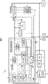
図1は、本発明を適用した車両の電気系統の一実施の形態を示すブロック図である。図1の電気系統1は、EV(Electric Vehicle、電気自動車)、HEV(Hybrid Electric Vehicle、ハイブリッドカー)、PHEV(Plug-in Hybrid Electric Vehicle、プラグインハイブリッドカー)など、バッテリに蓄えられた電力を用いて走行する電動車両に設けられる電気系統のうち、主に低圧(例えば、12V)の電気部品である低圧系負荷への電力の供給に関わる部分を示している。なお、低圧系負荷は、例えば、各種のECU(Electronic Control Unit)、パワーウインドウ用のモータ、照明ランプなどを含み、図1に示されるように、+B負荷2、ACC(アクセサリ)負荷3、および、IG(イグニッション)負荷4の3系統に分類される。また、以下、電気系統1が設けられている車両を自車と称する。
FIG. 1 is a block diagram showing an embodiment of an electric system of a vehicle to which the present invention is applied. The
電気系統1は、DCDCコンバータ11、低圧バッテリ12、IVTセンサ13、電流センサ回路14、低圧系J/B(Junction Box)15、低圧系電源ECU(Electronic Control Unit)16、スイッチ17、高圧バッテリ18、BMU(Battery Management Unit)19、高圧系J/B(Junction Box)20、高圧系電源ECU(Electronic Control Unit)21、および、車両ECU(Electronic Control Unit)22を含むように構成される。
The
DCDCコンバータ11は、電圧変換部31、出力電圧検出回路32、出力電流検出回路33、加熱保護温度センサ34、制御用自立電源回路35、および、制御部36を含むように構成される。
The DCDC converter 11 is configured to include a
電圧変換部31は、制御部36の制御の基に、高圧系J/B20を介して高圧バッテリ18から供給される電力の電圧を変換し、低圧バッテリ12および低圧系J/B15に供給する。電圧変換部31は、フィルタ回路41、パワー素子フルブリッジ回路42、絶縁トランス43、および、整流平滑回路44を含むように構成される。
The
フィルタ回路41は、高圧系J/B20を介して高圧バッテリ18から供給される電圧のノイズを除去し、パワー素子フルブリッジ回路42に供給する。
The filter circuit 41 removes noise from the voltage supplied from the
パワー素子フルブリッジ回路42は、例えば、トランジスタ、MOSFET(Metal-Oxide-Semiconductor Field-Effect Transistor)、IGBT(Insulated Gate Bipolar Transistor)、IPM(Intelligent Power Module)などの電力用半導体スイッチング素子を用いたフルブリッジ回路により構成される。パワー素子フルブリッジ回路42は、制御部36のパルストランス回路54から供給されるスイッチング信号に基づいて、高圧系J/B20を介して高圧バッテリ18から供給される直流電圧を交流電圧に変換し、絶縁トランス43に供給する。
The power element
絶縁トランス43は、DCDCコンバータ11の入力と出力を絶縁するとともに、パワー素子フルブリッジ回路42から供給される交流電圧を所定の変圧比で変圧し、整流平滑回路44に供給する。
The insulating
整流平滑回路44の2つの出力端子のうち一方は、低圧バッテリ12の+端子、および、低圧系J/B15に接続され、他方は接地されている。整流平滑回路44は、絶縁トランス43から供給される交流電圧を直流電圧に整流および平滑化し、低圧バッテリ12および低圧系J/B15に供給する。
One of the two output terminals of the rectifying / smoothing
出力電圧検出回路32は、DCDCコンバータ11の出力電圧を検出し、検出値を示す信号を制御部36のCPU51およびエラーアンプ52に供給する。
The output
出力電流検出回路33は、DCDCコンバータ11の出力電流を検出し、検出値を示す信号を制御部36のCPU51およびPWM IC53に供給する。
The output
加熱保護温度センサ34は、DCDCコンバータ11の温度を検出し、検出値を示す信号を制御部36のCPU51に供給する。
The heating
制御用自立電源回路35は、高圧系J/B20を介して高圧バッテリ18から供給される電力から、制御部36の駆動電力を生成し、制御部36に供給する。
The control self-supporting
制御部36は、CPU51、エラーアンプ52、PWM IC53、および、パルストランス回路54を含むように構成される。
The
CPU51は、低圧バッテリ12の電圧、電流および温度の検出値を示す信号を、IVTセンサ13から取得する。また、CPU51は、電流センサ回路14により検出される低圧系負荷への負荷電流の検出値を示す信号を取得する。CPU51は、DCDCコンバータ11の出力電圧、出力電流および温度、低圧バッテリ12の電圧、電流および温度、並びに、自車の低圧系負荷への負荷電流に基づいて、DCDCコンバータ11の出力の開始および停止を制御したり、DCDCコンバータ11の出力電圧の目標値(以下、目標電圧と称する)を設定したりする。CPU51は、DCDCコンバータ11の目標電圧を示す信号をエラーアンプ52に供給する。
The
エラーアンプ52は、出力電圧検出回路32からの信号の値とCPU51からの信号の値の差分、すなわち、DCDCコンバータ11の出力電圧と目標電圧の差分を増幅し、PWM IC53に供給する。
The
PWM IC53は、エラーアンプ52から供給される信号に基づいて、DCDCコンバータ11の出力電圧が目標電圧となるように、パルストランス回路54に供給するPWM(Pulse Width Modulation)信号のデューティ比を制御するとともに、パルストランス回路54の出力の開始および停止を制御する。
The
パルストランス回路54は、PWM IC53からのPWM信号に基づくスイッチング信号をパワー素子フルブリッジ回路42に供給し、パワー素子フルブリッジ回路42のスイッチングを制御することにより、DCDCコンバータ11の出力電圧を制御する。
The
低圧バッテリ12は、高圧系J/B20およびDCDCコンバータ11を介して高圧バッテリ18から供給される電力により充電されるとともに、低圧系J/B15を介して、+B負荷2、ACC負荷3、および、IG負荷4に電力を供給する。なお、低圧バッテリ12の−端子は接地されている。
The low-
IVTセンサ13は、低圧バッテリ12の電圧(例えば、低圧バッテリ12の+端子と−端子との間の電圧)、電流および温度を検出する。IVTセンサ13は、低圧バッテリ12の電圧、電流および温度の検出値を示す信号を、CAN(Controller Area Network)を介して、低圧系電源ECU16、BMU19、高圧系電源ECU21、車両ECU22、および、CPU51に供給する。
The
電流センサ回路14は、低圧バッテリ12と低圧系J/B15の間に設けられ、DCDCコンバータ11または低圧バッテリ12から低圧系J/B15を介して低圧系負荷に供給される負荷電流を検出する。電流センサ回路14は、負荷電流の検出値を示す信号を、CANを介して、低圧系電源ECU16、BMU19、高圧系電源ECU21、車両ECU22、および、CPU51に供給する。
The
低圧系J/B15は、例えば、コンタクタ、リレーなどを内蔵し、低圧系電源ECU16の制御の基に、+B負荷2、ACC負荷3、および、IG負荷4への電力の供給の有無を切替える。
The low-voltage system J /
スイッチ17は、例えば、イグニッションキースイッチもしくはスタータスイッチ、または、その両方により構成される。
The
例えば、自車の走行用または高圧バッテリ18の充電用のエンジンを搭載するHEVまたはPHEVにより自車が構成される場合、スイッチ17は、例えば、LOCKまたはOFF(以下、OFFに統一する)、ACC(アクセサリ)、IG(イグニッション)またはON(以下、ONに統一する)、STARTの4つの位置に設定することができる。
For example, when the vehicle is composed of a HEV or PHEV equipped with an engine for running the vehicle or charging the high-
この場合、スイッチ17の位置がOFFに設定された場合、自車のエンジンおよび主動力モータを稼動できず、自車が走行できない状態に設定される。また、低圧系電源ECU16の制御の基に、低圧系負荷のうち+B負荷2にのみ給電可能な状態となる。
In this case, when the position of the
また、スイッチ17の位置がACCに設定された場合、OFFに設定された場合と同様に、自車のエンジンおよび主動力モータを稼動できず、自車が走行できない状態に設定される。また、低圧系電源ECU16の制御の基に、低圧系負荷のうち+B負荷2およびACC負荷3に給電可能な状態となる。
Further, when the position of the
さらに、スイッチ17の位置がONに設定された場合、自車のエンジンおよび主動力モータの稼動が可能となり、自車が走行可能な状態に設定される。また、低圧系電源ECU16の制御の基に、+B負荷2、ACC負荷3およびIG負荷4の全ての低圧系負荷に給電可能な状態となる。
Furthermore, when the position of the
また、スイッチ17の位置がSTARTに設定された場合、自車のエンジンが点火し、エンジンが始動する。また、低圧系電源ECU16の制御の基に、+B負荷2、ACC負荷3およびIG負荷4の全ての低圧系負荷に給電可能な状態となる。なお、車両の種類によっては、スイッチ17の位置がSTARTに設定された場合、セルフスタータモータを始動させるために、ACC負荷3への給電が停止される場合もある。
Further, when the position of the
このように、自車がHEVまたはPHEVにより構成される場合、電気系統1は、スイッチ17の設定位置に関わらず、+B負荷2に常時給電可能であり、スイッチ17の位置がACC、ONまたはSTARTに設定されたとき、ACC負荷3に給電可能となり、スイッチ17の位置がONまたはSTARTに設定されたとき、IG負荷4に給電可能となる。
Thus, when the own vehicle is configured by HEV or PHEV, the
また、例えば、エンジンを搭載しないEVにより自車が構成される場合、スイッチ17は、例えば、LOCKまたはOFF(以下、OFFに統一する)、ACC(アクセサリ)、STARTまたはON(以下、ONに統一する)の3つの位置に設定することができる。
For example, when the vehicle is composed of an EV not equipped with an engine, the
この場合、スイッチ17の位置がOFFに設定された場合、主動力モータを稼動できず、自車が走行できない状態に設定される。また、低圧系電源ECU16の制御の基に、低圧系負荷のうち+B負荷2にのみ給電可能な状態となる。
In this case, when the position of the
また、スイッチ17の位置がACCに設定された場合、OFFに設定された場合と同様に、自車の主動力モータを稼動できず、自車が走行できない状態に設定される。また、低圧系電源ECU16の制御の基に、低圧系負荷のうち+B負荷2およびACC負荷3に給電可能な状態となる。
In addition, when the position of the
さらに、スイッチ17の位置がONに設定された場合、自車の主動力モータの稼動が可能となり、自車が走行可能な状態に設定される。また、低圧系電源ECU16の制御の基に、+B負荷2、ACC負荷3およびIG負荷4の全ての低圧系負荷に給電可能な状態となる。
Further, when the position of the
このように、自車がEVにより構成される場合、電気系統1は、スイッチ17の設定位置に関わらず、+B負荷2に常時給電可能であり、スイッチ17の位置がACCまたはONに設定されたとき、ACC負荷3に給電可能となり、スイッチ17の位置がONに設定されたとき、IG負荷4に給電可能となる。
Thus, when the own vehicle is configured by EV, the
なお、以下、+B負荷2のみに給電可能な状態を+B給電モードと称し、+B負荷2およびACC負荷3に給電可能な状態をACC給電モードと称し、+B負荷2、ACC負荷3およびIG負荷4の全ての低圧系負荷に給電可能な状態をIG給電モードと称する。ただし、後述するように、ユーザ設定や低圧バッテリ12の電圧などの要因により、負荷によっては、給電可能なモードであっても、給電が停止されるものがある。
Hereinafter, a state in which power can be supplied only to +
スイッチ17は、スイッチ17の設定位置を示す信号を、CANを介して、低圧系電源ECU16、BMU19、高圧系電源ECU21、車両ECU22、および、CPU51に供給する。
The
高圧バッテリ18は、自車の動力源として用いられる。具体的には、高圧バッテリ18に蓄えられている電力は、高圧系J/B20を介して、図示せぬ走行系インバータに供給され、直流電力から交流電力に変換される。そして、その交流電力が図示せぬ主動力モータに供給され、主動力モータが駆動されることにより、自車が走行する。また、高圧バッテリ18は、高圧系J/B20を介して、主動力モータ以外の自車の高圧系負荷にも電力を供給する。
The
BMU19は、高圧バッテリ18の管理を行う。例えば、BMU19は、高圧バッテリ18の状態(例えば、電圧、電流、温度など)を監視し、監視結果を示す情報を、CANを介して、低圧系電源ECU16、高圧系電源ECU21、車両ECU22、および、CPU51に供給する。
The BMU 19 manages the
高圧系J/B20は、例えば、コンタクタ、リレーなどを内蔵し、高圧系電源ECU21の制御の基に、DCDCコンバータ11、および、自車の高圧系負荷への電力の供給の有無を切替える。 The high-voltage system J / B 20 includes, for example, a contactor, a relay, and the like, and switches whether to supply power to the DCDC converter 11 and the high-voltage system load of the own vehicle based on the control of the high-voltage system power supply ECU 21.
車両ECU22は、図示せぬ走行系インバータなどの制御を行う。また、低圧系電源ECU16、BMU19、高圧系電源ECU21、車両ECU22、および、CPU51は、CANを介して通信し、各種の情報の送受信を行う。
The
図2は、低圧系電源ECU16、高圧系電源ECU21、および、車両ECU22が所定の制御プログラムを実行することにより実現される機能の構成の例の一部を示すブロック図である。具体的には、低圧系電源ECU16、高圧系電源ECU21、および、車両ECU22が所定の制御プログラムを実行することにより、電力制御部101を含む機能が実現される。また、電力制御部101は、スイッチ位置検出部111、低圧バッテリ状態監視部112、車両状態監視部113、低圧バッテリ充電制御部114、低圧系負荷給電制御部115、高圧系負荷給電制御部116、走行可能距離演算部117、および、通知制御部118を含むように構成される。
FIG. 2 is a block diagram showing a part of an example of a functional configuration realized by the low-voltage power supply ECU 16, the high-voltage power supply ECU 21, and the
スイッチ位置検出部111は、CANを介して供給されるスイッチ17からの信号に基づいて、スイッチ17の設定位置を検出する。スイッチ位置検出部111は、検出結果を示す情報を、低圧バッテリ状態監視部112、車両状態監視部113、低圧バッテリ充電制御部114、低圧系負荷給電制御部115、高圧系負荷給電制御部116、および、走行可能距離演算部117に供給する。
The
低圧バッテリ状態監視部112は、CANを介して供給されるIVTセンサ13からの信号に基づいて、低圧バッテリ12の状態を監視する。低圧バッテリ状態監視部112は、監視結果を示す情報を、低圧バッテリ充電制御部114、低圧系負荷給電制御部115、および、通知制御部118に供給する。
The low voltage battery
車両状態監視部113は、CANを介して、BMU19、DCDCコンバータ11のCPU51、その他の各種のECU、電装部品などと通信を行ったり、電流センサ回路14などの各種のセンサからの信号を取得したりして、自車の各部の状態、異常の発生の有無などを監視する。車両状態監視部113は、監視結果を示す情報を、低圧バッテリ充電制御部114、低圧系負荷給電制御部115、高圧系負荷給電制御部116、走行可能距離演算部117、および、通知制御部118に供給する。
The vehicle
また、車両状態監視部113は、CANを介して図示せぬ操作部から供給される情報に基づいて、ユーザによる給電を停止する負荷の設定に関する情報を取得し、取得した情報を低圧系負荷給電制御部115および走行可能距離演算部117に供給する。
Further, the vehicle
低圧バッテリ充電制御部114は、CANを介して、DCDCコンバータ11のCPU51に指令を与え、DCDCコンバータ11による低圧バッテリ12の充電を制御する。また、低圧バッテリ充電制御部114は、高圧系負荷給電制御部116に指令を与え、高圧バッテリ18からDCDCコンバータ11への給電を制御する。
The low voltage battery
低圧系負荷給電制御部115は、CANを介して、低圧系J/B15を制御して、低圧系負荷への給電を制御する。
The low voltage system load power
高圧系負荷給電制御部116は、CANを介して、高圧系J/B20を制御して、高圧系負荷への給電を制御する。
The high voltage system load power
走行可能距離演算部117は、CANを介して、BMU19から高圧バッテリ18のSOC(State of Charge、残容量)を示す情報を取得する。走行可能距離演算部117は、高圧バッテリ18のSOCで走行可能な距離を演算し、演算結果を示す情報を通知制御部118に供給する。
The travelable
通知制御部118は、通知部102を介して、自車の状態、走行可能距離、運転者への警告などの各種の通知を行う。
The
通知部102は、例えば、カーナビゲーションシステム、インストルメントパネル、ディスプレイ、ランプ、LED(Light Emitting Diode)、スピーカなどにより構成され、上述したように、通知制御部118の制御の基に、映像、光、音声などを用いて各種の通知を行う。なお、通知部102を構成する各部は、それぞれ+B負荷2、ACC負荷3、および、IG負荷4のいずれかに含まれる。
The
次に、図3乃至図6を参照して、電気系統1により実行される処理について説明する。
Next, processing executed by the
まず、図3のフローチャートを参照して、ACC負荷モード時の電力制御処理について説明する。なお、この処理は、例えば、スイッチ17の位置がACCに設定されたとき開始され、ACC以外に設定されたとき終了する。また、スイッチ17の位置がACCに設定されたとき、スイッチ位置検出部111は、スイッチ17の位置がACCに設定されたことを、低圧バッテリ状態監視部112、車両状態監視部113、低圧バッテリ充電制御部114、低圧系負荷給電制御部115、高圧系負荷給電制御部116、および、走行可能距離演算部117に通知する。
First, the power control process in the ACC load mode will be described with reference to the flowchart of FIG. This process is started when the position of the
ステップS1において、低圧バッテリ充電制御部114は、DCDCコンバータ11の出力が行われている場合、DCDCコンバータ11の出力を停止する。具体的には、低圧バッテリ充電制御部114は、DCDCコンバータ11のCPU51に出力の停止を指令する。CPU51は、目標電圧を示す信号のエラーアンプ52への供給を停止する。これにより、PWM IC53からパルストランス回路54へのPWM信号の供給が停止され、DCDCコンバータ11の出力が停止し、低圧バッテリ12の充電が停止する。
In step S <b> 1, the low voltage battery
ステップS2において、高圧系J/B20は、高圧系負荷給電制御部116の制御の基に、高圧系負荷への給電が行われている場合、高圧系負荷への給電を停止する。このとき、DCDCコンバータ11への給電が停止され、DCDCコンバータ11が停止する。
In step S <b> 2, the high voltage system J / B 20 stops power supply to the high voltage system load when power supply to the high voltage system load is performed based on the control of the high voltage system load power
ステップS3において、車両状態監視部113は、走行不能な故障が発生した履歴が残っているか否かを判定する。車両状態監視部113は、走行不能な故障が発生した履歴が残っていると判定した場合、走行不能な故障が発生した履歴が残っていることを低圧系負荷給電制御部115に通知する。その後、処理はステップS4に進む。
In step S <b> 3, the vehicle
なお、この走行不能な故障が発生した履歴は、後述する図5のステップS66において、走行不能な故障が発生していると判定されたとき記録され、走行不能な故障が解消されたとき消去される。 It should be noted that the history of the occurrence of the inoperable failure is recorded when it is determined in step S66 in FIG. 5 described later that the inoperable failure has occurred, and is erased when the inoperable failure is resolved. The
ステップS4において、低圧系負荷給電制御部115は、低圧バッテリ12の電圧低下時のACC負荷給電停止機能を無効にする。その後、処理はステップS5に進む。
In step S4, the low-voltage load power
一方、ステップS3において、走行不能な故障が発生した履歴が残っていないと判定された場合、ステップS4の処理はスキップされ、処理はステップS5に進む。 On the other hand, if it is determined in step S3 that there is no history of occurrence of a failure that cannot be driven, the process of step S4 is skipped, and the process proceeds to step S5.
ステップS5において、低圧バッテリ状態監視部112は、低圧バッテリ12の電圧が充電開始電圧以下であるか否かを判定する。具体的には、低圧バッテリ状態監視部112は、IVTセンサ13からの信号に基づいて、低圧バッテリ12の電圧が充電開始電圧以下であるか否かを判定し、低圧バッテリ12の電圧が充電開始電圧以下になるまで、処理が待機される。そして、低圧バッテリ状態監視部112は、低圧バッテリ12の電圧が充電開始電圧以下になったと判定した場合、低圧バッテリ12の電圧が充電開始電圧以下になったことを、低圧バッテリ充電制御部114、低圧系負荷給電制御部115、および、通知制御部118に通知する。その後、処理はステップS6に進む。
In step S5, the low voltage battery
なお、充電開始電圧は、例えば、低圧バッテリ12の放電終止電圧、または、低圧系負荷の駆動電圧の最小値付近の値に設定される。
The charging start voltage is set to a value near the minimum value of the discharge end voltage of the
ステップS6において、低圧系負荷給電制御部115は、低圧バッテリ12の電圧低下時のACC負荷給電停止機能が有効であるか否かを判定する。低圧バッテリ12の電圧低下時のACC負荷給電停止機能が無効であると判定された場合、処理はステップS7に進む。
In step S <b> 6, the low voltage system load power
ステップS7において、通知部102は、通知制御部118の制御の基に、低圧バッテリ12の電圧低下および充電中の通知を行う。例えば、通知部102は、通知制御部118の制御の基に、ディスプレイに警告画面を表示したり、LEDやランプなどを点灯または点滅させたり、音声ガイダンスを出力したり、警告音を鳴動したりするなどの方法により、低圧バッテリ12の電圧が低下したこと、および、低圧バッテリ12が充電中であることを通知する。
In step S <b> 7, the
なお、このとき、例えば、自車がHEVまたはPHEVであり、エンジンの稼動時に発電機により低圧バッテリ12の充電を行うことが可能な場合、自車のエンジンの始動を促す通知を行うようにしてもよい。
At this time, for example, if the host vehicle is HEV or PHEV and the
ステップS8において、高圧系J/B20は、DCDCコンバータ11への給電を開始する。具体的には、低圧バッテリ充電制御部114は、DCDCコンバータ11への給電を高圧系負荷給電制御部116に指令する。高圧系J/B20は、高圧系負荷給電制御部116の制御の基に、DCDCコンバータ11への給電を開始する。これにより、制御用自立電源回路35から制御部36への電力の供給が開始され、DCDCコンバータ11が起動する。
In step S <b> 8, the high voltage system J / B 20 starts supplying power to the DCDC converter 11. Specifically, the low voltage battery
ステップS9において、DCDCコンバータ11の制御部36は、DCDCコンバータ11の出力を開始させ、低圧バッテリ12の充電を開始する。具体的には、低圧バッテリ充電制御部114は、低圧バッテリ12の充電の開始を、DCDCコンバータ11のCPU51に指令する。CPU51は、DCDCコンバータ11の目標電圧を設定し、設定した目標電圧を示す信号のエラーアンプ52への供給を開始する。PWM IC53は、パルストランス回路54へのPWM信号の供給を開始するとともに、エラーアンプ52から供給される信号に基づいて、DCDCコンバータ11の出力電圧が目標電圧となるようにPWM信号のデューティ比を制御する。パルストランス回路54は、PWM IC53の制御の基に、PWM信号に基づくスイッチング信号のパワー素子フルブリッジ回路42への供給を開始する。これにより、パワー素子フルブリッジ回路42が起動し、DCDCコンバータ11の出力が開始され、DCDCコンバータ11から低圧バッテリ12への充電電流の供給が開始される。
In step S <b> 9, the
なお、このときDCDCコンバータ11は、例えば、まず出力電圧を低圧バッテリ12と同じ電圧に設定した後、充電電流が通常の充電電流より低い値(例えば、低圧バッテリ12の5時間放電率の電流(5時間率電流)の1/5〜1/2)以下となるように出力電圧を制御しながら、低圧バッテリ12の充電を行う。
At this time, for example, the DCDC converter 11 first sets the output voltage to the same voltage as that of the
ステップS10において、低圧バッテリ状態監視部112は、IVTセンサ13からの信号に基づいて、低圧バッテリ12の電圧が規定電圧以上であるか否かを判定する。低圧バッテリ12の電圧が規定電圧以上でないと判定された場合、処理はステップS11に進む。なお、この規定電圧は、例えば、充電開始電圧より所定の値(例えば、1.0V)だけ大きい電圧に設定される。
In step S <b> 10, the low voltage battery
ステップS11において、低圧バッテリ状態監視部112は、低圧バッテリ12の充電電流が0Aになったか否かを判定する。低圧バッテリ12の充電電流が0Aになっていないと判定された場合、処理はステップS10に戻る。
In step S11, the low voltage battery
その後、ステップS10において、低圧バッテリ12の電圧が規定電圧以上であると判定されるか、ステップS11において、低圧バッテリ12の充電電流が0Aになったと判定されるまで、ステップS10およびS11の処理が繰り返し実行される。
Thereafter, the processes in steps S10 and S11 are performed until it is determined in step S10 that the voltage of the
一方、ステップS10において、低圧バッテリ状態監視部112は、低圧バッテリの電圧が規定電圧以上であると判定した場合、低圧バッテリ12の電圧が規定電圧以上になったことを、低圧バッテリ充電制御部114、低圧系負荷給電制御部115、および、通知制御部118に通知する。その後、処理はステップS12に進む。
On the other hand, when the low voltage battery
ステップS12において、ステップS1の処理と同様に、DCDCコンバータ11の出力が停止され、低圧バッテリ12の充電が停止する。
In step S12, as in the process of step S1, the output of the DCDC converter 11 is stopped, and charging of the low-
なお、故障が発生して停車している場合、走行時に比べて低圧系負荷による消費電力が小さくなるため、充電電流および充電を停止する電圧は、通常より低い値に設定される。 Note that, when the vehicle is stopped due to a failure, the power consumption due to the low-voltage load is smaller than when traveling, so the charging current and the voltage at which charging is stopped are set to values lower than normal.
ステップS13において、高圧系J/B20は、DCDCコンバータ11への給電を停止する。具体的には、低圧バッテリ充電制御部114は、DCDCコンバータ11への給電の停止を高圧系負荷給電制御部116に指令する。高圧系J/B20は、高圧系負荷給電制御部116の制御の基に、DCDCコンバータ11への給電を停止する。これにより、DCDCコンバータ11が停止する。
In step S <b> 13, the high voltage system J / B 20 stops supplying power to the DCDC converter 11. Specifically, the low voltage battery
ステップS14において、通知部102は、通知制御部118の制御の基に、低圧バッテリ12の電圧低下および充電中の通知を停止する。
In step S <b> 14, the
その後、処理はステップS5に戻り、ステップS5以降の処理が実行される。 Thereafter, the process returns to step S5, and the processes after step S5 are executed.
一方、ステップS11において、低圧バッテリ状態監視部112は、低圧バッテリ12の充電電流が0Aになったと判定した場合、低圧バッテリ12の充電電流が0Aになったことを低圧バッテリ充電制御部114に通知する。その後、処理はステップS15に進む。
On the other hand, when the low voltage battery
なお、これは、例えば、高圧バッテリ18の容量の低下に伴い、DCDCコンバータ11への入力電圧が低下することにより、DCDCコンバータ11から低圧バッテリ12に充電電流を供給することができなくなった場合である。
For example, this is a case where the charging current cannot be supplied from the DCDC converter 11 to the
ステップS15において、ステップS1の処理と同様に、DCDCコンバータ11の出力が停止され、ステップS16において、ステップS13の処理と同様に、DCDCコンバータ11への給電が停止される。その後、ACC給電モード時の電力制御処理は終了する。 In step S15, the output of the DCDC converter 11 is stopped as in the process of step S1, and in step S16, the power supply to the DCDC converter 11 is stopped as in the process of step S13. Thereafter, the power control process in the ACC power supply mode ends.
一方、ステップS6において、低圧バッテリ12の電圧低下時のACC負荷給電停止機能が有効であると判定された場合、処理はステップS17に進む。
On the other hand, when it is determined in step S6 that the ACC load power supply stop function when the voltage of the
ステップS17において、通知部102は、通知制御部118の制御の基に、ステップS7と同様の処理により、低圧バッテリ12の電圧低下の通知を行う。
In step S <b> 17, the
ステップS18において、低圧系J/B15は、低圧系負荷給電制御部115の制御の基に、ACC負荷3への給電を停止する。その後、ACC給電モード時の電力制御処理は終了する。
In step S <b> 18, the low voltage system J /
次に、図4乃至図6のフローチャートを参照して、IG給電モード時の電力制御処理について説明する。なお、この処理は、例えば、スイッチ17の位置がIGまたはSTARTに設定されたとき開始され、IGおよびSTART以外に設定されたとき終了する。また、スイッチ17の位置がIGまたはSTARTに設定されたとき、スイッチ位置検出部111は、スイッチ17の位置がIGまたはSTARTに設定されたことを、低圧バッテリ状態監視部112、車両状態監視部113、低圧バッテリ充電制御部114、低圧系負荷給電制御部115、高圧系負荷給電制御部116、および、走行可能距離演算部117に通知する。
Next, power control processing in the IG power supply mode will be described with reference to the flowcharts of FIGS. This process is started when the position of the
ステップS51において、車両状態監視部113は、車両電装システムをチェックする。具体的には、車両状態監視部113は、自車の各電装部品、または、電装部品を制御するECUと通信を行い、自車に装備されている電装部品の種類、稼動状態、消費電力などをチェックする。
In step S51, the vehicle
ステップS52において、走行可能距離演算部117は、走行可能距離を演算する。具体的には、走行可能距離演算部117は、車両状態監視部113から、自車の各電装部品の消費電力や稼動状態などを示す情報を取得する。また、走行可能距離演算部117は、BMU19から高圧バッテリ18の残量を示す情報を取得する。走行可能距離演算部117は、取得した情報に基づいて、現在の高圧バッテリ18の残量で走行可能な距離を演算する。走行可能距離演算部117は、演算した走行可能距離を示す情報を通知制御部118に供給する。
In step S52, the travelable
ステップS53において、通知部102は、走行可能距離と給電停止選択項目を表示する。具体的には、通知制御部118は、低圧系負荷のうち給電停止の選択が可能な各負荷について、給電停止が選択されているか否かを示す情報を、車両状態監視部113から取得する。通知部102は、通知制御部118の制御の基に、走行可能距離演算部117により演算された自車の走行可能距離、並びに、給電停止の選択が可能な各負荷の一覧および給電停止の選択の有無を示す画面を表示する。
In step S53, the
なお、給電停止の選択が可能な負荷としては、例えば、エアコンディショナ(A/C)、パワーシート、リヤワイパー、デフォッガー、室内照明などのボディ系コンフォート機能負荷、カーオーディオシステム、シガーライターソケットなどのアクセサリ系負荷などが含まれる。 Loads that can be selected to stop power supply include, for example, air conditioners (A / C), power seats, rear wipers, defogger, body system comfort function loads such as indoor lighting, car audio systems, cigarette lighter sockets, etc. The accessories system load etc. are included.
ステップS54において、車両状態監視部113は、給電を停止する負荷が変更されたか否かを判定する。例えば、運転者は、ステップS53の処理により表示された画面を見て、走行可能距離を考慮しながら、図示せぬ操作部を用いて、給電停止する負荷の追加や、給電停止中の負荷の給電停止の解除を行う。操作部は、給電を停止する負荷の追加や、給電停止中の負荷の給電停止の解除が行われた場合、操作内容を示す情報を車両状態監視部113に供給する。車両状態監視部113は、操作内容を示す情報を取得した場合、給電を停止する負荷が変更されたと判定し、処理はステップS55に進む。
In step S54, the vehicle
ステップS55において、低圧系J/B15は、給電を停止する負荷を変更する。具体的には、車両状態監視部113は、給電を停止する負荷の変更内容を示す情報を低圧系負荷給電制御部115および走行可能距離演算部117に供給する。低圧系J/B15は、低圧系負荷給電制御部115の制御の基に、新たに給電を停止するように設定された負荷への給電を停止し、給電停止が解除された負荷への給電を再開する。
In step S55, the low-pressure system J /
その後、処理はステップS52に戻り、ステップS54において、給電を停止する負荷が変更されなかったと判定されるまで、ステップS52乃至S55の処理が繰り返し実行される。これにより、給電を停止する負荷の変更に伴い、走行可能距離が再演算され、走行可能距離と給電停止選択項目の表示が更新される。 Thereafter, the process returns to step S52, and the processes of steps S52 to S55 are repeatedly executed until it is determined in step S54 that the load for stopping power feeding has not been changed. Accordingly, the travelable distance is recalculated with the change of the load for stopping the power supply, and the display of the travelable distance and the power supply stop selection item is updated.
一方、ステップS54において、例えば、所定の時間、給電を停止する負荷の変更が行われなかった場合、または、明示的に給電停止項目の設定を終了するための操作が行われた場合、ステップS54において、車両状態監視部113は、給電を停止する負荷が変更されていないと判定し、処理はステップS56に進む。
On the other hand, in step S54, for example, when the load for stopping the power supply is not changed for a predetermined time, or when an operation for explicitly terminating the setting of the power supply stop item is performed, step S54 is performed. The vehicle
ステップS56において、車両状態監視部113は、各種ECUおよび高圧バッテリ18に異常が発生していないか否かを判定する。具体的には、車両状態監視部113は、各種ECUおよびBMU19と通信を行い、異常が発生していないか否かを確認する。その結果、車両状態監視部113は、各種ECUおよび高圧バッテリ18のうち少なくとも1つの異常が発生していると判定した場合、各種ECUおよび高圧バッテリ18に異常が発生していることを通知制御部118に通知する。その後、処理はステップS57に進む。
In step S56, the vehicle
ステップS57において、通知部102は、通知制御部118の制御の基に、図3のステップS7と同様の処理により、各種ECUおよび高圧バッテリ18の異常の発生を通知する。その後、IG給電モード時の電力制御処理は終了する。
In step S57, the
一方、ステップS56において、車両状態監視部113は、各種ECUおよび高圧バッテリ18に異常が発生していないと判定した場合、各種ECUおよび高圧バッテリ18に異常が発生していないことを、高圧系負荷給電制御部116に通知する。その後、処理はステップS58に進む。
On the other hand, if the vehicle
ステップS58において、高圧系J/B20は、高圧系負荷給電制御部116の制御の基に、高圧系負荷への給電を開始する。これにより、DCDCコンバータ11への給電が開始され、DCDCコンバータ11が起動する。
In step S58, the high voltage system J / B 20 starts power supply to the high voltage system load based on the control of the high voltage system load power
ステップS59において、車両状態監視部113は、高圧系の電気系統において漏電が発生していないか否かを判定する。車両状態監視部113は、高圧系の電気系統において漏電が発生していると判定した場合、高圧系の電気系統において漏電が発生していることを、高圧系負荷給電制御部116および通知制御部118に通知する。その後、処理はステップS60に進む。
In step S59, the vehicle
ステップS60において、通知部102は、通知制御部118の制御の基に、図3のステップS7と同様の処理により、漏電の発生を通知する。その後、IG給電モード時の電力制御処理は終了する。
In step S <b> 60, the
一方、ステップS59において、高圧系の電気系統において漏電が発生していないと判定された場合、処理はステップS62に進む。 On the other hand, if it is determined in step S59 that no leakage has occurred in the high-voltage electrical system, the process proceeds to step S62.
ステップS62において、低圧バッテリ状態監視部112は、IVTセンサ13からの信号に基づいて、低圧バッテリ12の電圧が、セルフスタータモータの駆動が可能な電圧以上であるか否かを判定する。低圧バッテリ状態監視部112は、低圧バッテリ12の電圧が、セルフスタータモータの駆動が可能な電圧以上でないと判定した場合、低圧バッテリ12の電圧が、セルフスタータモータの駆動が可能な電圧以上でないことを、通知制御部118に通知する。その後、処理はステップS63に進む。
In step S62, the low-voltage battery
ステップS63において、通知部102は、通知制御部118の制御の基に、低圧バッテリ12の外部充電を促す。例えば、通知部102は、通知制御部118の制御の基に、ディスプレイに警告画面を表示したり、LEDやランプなどを点灯または点滅させたり、音声ガイダンスを出力したり、警告音を鳴動するなどの方法により、低圧バッテリ12の外部充電を促すための通知を行う。その後、IG給電モード時の電力制御処理は終了する。
In step S <b> 63, the
一方、ステップS62において、低圧バッテリ12の電圧が、セルフスタータモータの駆動が可能な電圧以上であると判定された場合、処理はステップS64に進む。
On the other hand, if it is determined in step S62 that the voltage of the
なお、ステップS62およびS63の処理は、HEVまたはPHEVなど、自車が走行用または高圧バッテリ18の充電用のエンジンを搭載する場合にのみ行われる。
The processes in steps S62 and S63 are performed only when the host vehicle is equipped with an engine for driving or charging the high-
ステップS64において、図3のステップS9の処理と同様に、DCDCコンバータ11の出力が開始され、低圧バッテリ12の充電が開始される。
In step S64, the output of the DCDC converter 11 is started and charging of the low-
なお、このときDCDCコンバータ11は、例えば、まず出力電圧を低圧バッテリ12と同じ電圧に設定した後、充電電流が所定の値(例えば、低圧バッテリ12の5時間率電流)以下となるように出力電圧を制御しながら、低圧バッテリ12の充電を行う。
At this time, for example, the DCDC converter 11 first sets the output voltage to the same voltage as that of the
ステップS65において、低圧バッテリ状態監視部112は、IVTセンサ13からの信号に基づいて、低圧バッテリ12の電圧が充電終了電圧に達したか否かを判定する。低圧バッテリ12の電圧が充電終了電圧に達していないと判定された場合、処理はステップS66に進む。なお、充電終了電圧は、例えば、低圧バッテリ12の充電終止電圧に設定される。
In step S <b> 65, the low voltage battery
ステップS66において、車両状態監視部113は、走行不能な故障が発生していないか否かを判定する。走行不能な故障が発生していないと判定された場合、処理はステップS65に戻る。
In step S <b> 66, the vehicle
その後、ステップS65において、低圧バッテリ12の電圧が充電終了電圧に達したと判定されるか、ステップS66において、走行不能な故障が発生していると判定されるまで、ステップS65およびS66の処理が繰り返し実行される。
Thereafter, the processes in steps S65 and S66 are performed until it is determined in step S65 that the voltage of the low-
一方、ステップS65において、低圧バッテリ12の電圧が充電終了電圧に達したと判定された場合、処理はステップS67に進む。
On the other hand, if it is determined in step S65 that the voltage of the
ステップS67において、図3のステップS1の処理と同様に、DCDCコンバータ11の出力が停止され、低圧バッテリ12の充電が停止する。
In step S67, the output of the DCDC converter 11 is stopped and charging of the low-
ステップS68において、図3のステップS5の処理と同様に、低圧バッテリ12の電圧が充電開始電圧以下であるか否かが判定される。低圧バッテリ12の電圧が充電開始電圧以下であると判定された場合、処理はステップS64に戻る。その後、ステップS64以降の処理が実行され、低圧バッテリ12の充電が行われる。
In step S68, it is determined whether or not the voltage of the
一方、ステップS68において、低圧バッテリ12の電圧が充電開始電圧以下でないと判定された場合、処理はステップS69に進む。
On the other hand, if it is determined in step S68 that the voltage of the
ステップS69において、車両状態監視部113は、高圧系負荷の電力要求が所定量以上であるか否かを判定する。高圧系負荷の電力要求が所定量以上でないと判定された場合、処理はステップS68に戻る。その後、ステップS68以降の処理が実行される。
In step S <b> 69, the vehicle
一方、ステップS69において、高圧系負荷の電力要求が所定量以上であると判定された場合、処理はステップS70に進む。 On the other hand, if it is determined in step S69 that the power demand of the high-voltage load is greater than or equal to the predetermined amount, the process proceeds to step S70.
ステップS70において、車両状態監視部113は、BMU19からの信号に基づいて、高圧バッテリ18のSOCが規定量以上であるか否かが判定される。高圧バッテリ18のSOCが規定量以上であると判定された場合、すなわち、高圧バッテリ18の容量に余裕がある場合、処理はステップS68に戻る。その後、ステップS68以降の処理が実行される。
In step S <b> 70, the vehicle
一方、ステップS70において、車両状態監視部113は、高圧バッテリ18のSOCが規定量未満であると判定した場合、すなわち、高圧バッテリ18の容量に余裕がない場合、高圧バッテリ18の容量に余裕がないことを通知制御部118に通知する。その後、処理はステップS71に進む。
On the other hand, if the vehicle
ステップS71において、通知部102は、通知制御部118の制御の基に、図3のステップS7と同様の処理により、高圧バッテリ18の残量警告を行う。
In step S <b> 71, the
ステップS72において、ステップS54の処理と同様に、給電を停止する負荷が変更されたか否かが判定される。給電を停止する負荷が変更されなかったと判定された場合、処理はステップS68に戻る。その後、ステップS68以降の処理が実行される。 In step S72, as in the process of step S54, it is determined whether or not the load for stopping power feeding has been changed. If it is determined that the load for stopping power feeding has not been changed, the process returns to step S68. Thereafter, the processing after step S68 is executed.
一方、ステップS72において、給電を停止する負荷が変更されたと判定された場合、処理はステップS73に進む。 On the other hand, when it determines with the load which stops electric power feeding having been changed in step S72, a process progresses to step S73.
ステップS73において、ステップS55の処理と同様に、給電を停止する負荷が変更され、ステップS74において、ステップS52の処理と同様に、走行可能距離が演算される。 In step S73, the load for stopping power feeding is changed in the same manner as in step S55. In step S74, the travelable distance is calculated in the same manner as in step S52.
ステップS75において、通知部102は、通知制御部118の制御の基に、ステップS53と同様の処理により、走行可能距離と給電停止選択項目の表示を更新する。その後、処理はステップS68に戻り、ステップS68以降の処理が実行される。
In step S <b> 75, the
一方、ステップS66において、車両状態監視部113は、走行不能な故障が発生していると判定した場合、走行不能な故障が発生していることを、低圧系負荷給電制御部115および通知制御部118に通知する。また、車両状態監視部113は、走行不能な故障が発生した履歴を記録する。その後、処理はステップS76に進む。
On the other hand, when the vehicle
ステップS76において、通知部102は、通知制御部118の制御の基に、図3のステップS7と同様の処理により、故障の発生を通知する。
In step S76, the
ステップS77において、低圧系J/B15は、低圧系負荷給電制御部115の制御の基に、給電が停止されているACC負荷3への給電を再開する。すなわち、図3のステップS18、図4のステップS55、または、図5のステップS73の処理により、給電が停止されているACC負荷3がある場合、そのACC負荷3への給電が再開される。
In step S77, the low-pressure system J /
ステップS78において、図3のステップS10の処理と同様に、低圧バッテリ12の電圧が規定電圧以上であるか否かが判定される。低圧バッテリ12の電圧が規定電圧以上でないと判定された場合、処理はステップS79に進む。
In step S78, it is determined whether or not the voltage of the
ステップS79において、図3のステップS11の処理と同様に低圧バッテリ12の充電電流が0Aになったか否かが判定される。低圧バッテリ12の充電電流が0Aになっていないと判定された場合、処理はステップS78に戻る。
In step S79, it is determined whether or not the charging current of the
その後、ステップS78において、低圧バッテリ12の電圧が規定電圧以上であると判定されるか、ステップS79において、低圧バッテリ12の充電電流が0Aになったと判定されるまで、ステップS78およびS79の処理が繰り返し実行される。
Thereafter, the process of steps S78 and S79 is performed until it is determined in step S78 that the voltage of the
一方、ステップS78において、低圧バッテリの電圧が規定電圧以上であると判定された場合、処理はステップS80に進む。 On the other hand, if it is determined in step S78 that the voltage of the low voltage battery is equal to or higher than the specified voltage, the process proceeds to step S80.
ステップS80において、図3のステップS12の処理と同様に、DCDCコンバータ11の出力が停止され、その結果、低圧バッテリ12の充電が停止する。
In step S80, similarly to the process in step S12 of FIG. 3, the output of the DCDC converter 11 is stopped, and as a result, charging of the
ステップS81において、図3のステップS13の処理と同様に、DCDCコンバータ11への給電が停止され、その結果、DCDCコンバータ11が停止する。 In step S81, similarly to the process in step S13 of FIG. 3, power supply to the DCDC converter 11 is stopped, and as a result, the DCDC converter 11 stops.
ステップS82において、図3のステップS5の処理と同様に、低圧バッテリ12の電圧が充電開始電圧以下であるか否かが判定され、低圧バッテリ12の電圧が充電開始電圧以下になるまで、処理が待機される。そして、低圧バッテリ12の電圧が充電開始電圧以下になったと判定された場合、処理はステップS83に進む。
In step S82, it is determined whether or not the voltage of the
ステップS83において、図3のステップS8の処理と同様に、DCDCコンバータ11への給電が開始され、ステップS84において、図3のステップS9の処理と同様に、DCDCコンバータ11の出力が開始される。これにより、低圧バッテリ12の充電が開始される。
In step S83, power supply to the DCDC converter 11 is started in the same manner as in step S8 in FIG. 3, and in step S84, output of the DCDC converter 11 is started in the same manner as in step S9 in FIG. Thereby, charging of the
なお、このときDCDCコンバータ11は、例えば、まず出力電圧を低圧バッテリ12と同じ電圧に設定した後、充電電流が通常の充電電流より低い値(例えば、低圧バッテリ12の5時間率電流の1/5〜1/2)以下となるように出力電圧を制御しながら、低圧バッテリ12の充電を行う。
At this time, for example, the DCDC converter 11 first sets the output voltage to the same voltage as that of the
その後、処理はステップS78に戻り、ステップS78以降の処理が実行される。 Thereafter, the process returns to step S78, and the processes after step S78 are executed.
一方、ステップS79において、低圧バッテリ12の充電電流が0Aになったと判定された場合、処理はステップS85に進む。
On the other hand, if it is determined in step S79 that the charging current of the
ステップS85において、図3のステップS15の処理と同様に、DCDCコンバータ11の出力が停止され、ステップS86において、図3のステップS16の処理と同様に、高圧系負荷への給電が停止される。その後、IG給電モード時の電力制御処理は終了する。 In step S85, the output of the DCDC converter 11 is stopped similarly to the process of step S15 of FIG. 3, and in step S86, the power supply to the high-voltage system load is stopped, similar to the process of step S16 of FIG. Thereafter, the power control process in the IG power supply mode ends.
以上のように、スイッチ17の位置がACCに設定されている場合、走行不能な故障が発生していないときには、低圧バッテリ12の充電が行われないが、走行不能な故障が発生しているときには、低圧バッテリ12の充電が行われる。従って、駐車中の高圧バッテリ18の容量の低下を抑制しつつ、故障で走行不能になった場合、高圧バッテリ18の電力を低圧バッテリ12に移すことができ、ACC負荷3への給電をより長く持続させることが可能になる。その結果、例えば、ACC負荷3に含まれる照明ランプやハザードランプなどの動作時間をできる限り長くすることができ、ロードサービス等の救援が到着するまでの安全の確保や情報の収集を行う時間をより長くすることができる。
As described above, when the position of the
また、以上のように、スイッチ17の位置がACCに設定されている場合、走行不能な故障が発生していないときには、ACC負荷3への給電が停止される。その結果、駐車中に低圧バッテリ12の容量がなくなり、自車の走行ができない状態になることを、より確実に防止することができる。
In addition, as described above, when the position of the
さらに、以上のように、ユーザの意思により、高圧バッテリ18および低圧バッテリ12の残存容量などから、稼動させる低圧系負荷を自由に設定することができる。すなわち、低圧系負荷の動作のプライオリティ制御が可能になる。従って、例えば、高圧バッテリ18および低圧バッテリ12の電力の消費を抑制し、自車の走行距離を延長させることが可能である。その結果、例えば、救援を呼べなかったり、呼びづらい場所(例えば、高速度路や山間僻地など)での停車を、より確実に避けることができる。
Furthermore, as described above, the low-voltage load to be operated can be freely set based on the remaining capacity of the high-
なお、予め設定された優先順位に従って、高圧バッテリ18の容量が低下するに従って、自動的に低圧系負荷を停止していくようにしてもよい。
Note that the low-voltage system load may be automatically stopped as the capacity of the high-
また、上述した一連の電力制御部101の処理は、ハードウエアにより実行するようにすることも可能である。
The series of processes of the
さらに、電力制御部101の処理をソフトウエアにより実行する場合、電力制御部101の処理を実現するためのプログラムは、例えば、電気系統1の図示せぬ記録媒体に予めインストールしておくことも可能であるし、または、例えば、磁気ディスク(フレキシブルディスクを含む)、光ディスク(CD-ROM(Compact Disc-Read Only Memory),DVD(Digital Versatile Disc)等)、光磁気ディスク、もしくは半導体メモリなどよりなるパッケージメディアであるリムーバブルメディアに記録して、あるいは、ローカルエリアネットワーク、インターネット、デジタル衛星放送といった、有線または無線の伝送媒体を介して提供し、インストールすることも可能である。
Further, when the processing of the
また、電力制御部101の処理を実現するためのプログラムは、本明細書で説明する順序に沿って時系列に処理が行われるプログラムであっても良いし、並列に、あるいは呼び出しが行われたとき等の必要なタイミングで処理が行われるプログラムであっても良い。
The program for realizing the processing of the
さらに、本発明の実施の形態は、上述した実施の形態に限定されるものではなく、本発明の要旨を逸脱しない範囲において種々の変更が可能である。 Furthermore, the embodiments of the present invention are not limited to the above-described embodiments, and various modifications can be made without departing from the gist of the present invention.
1 電気系統
2 +B負荷
3 ACC負荷
4 IG負荷
11 DCDCコンバータ
12 低圧バッテリ
13 IVTセンサ
14 電流センサ回路
15 低圧系J/B
16 低圧系電源ECU
17 スイッチ
18 高圧バッテリ
19 BMU
20 高圧系J/B
21 高圧系電源ECU
22 車両ECU
31 電圧変換部
32 出力電圧検出回路
33 出力電流検出回路
36 制御部
51 CPU
101 電力制御部
102 通知部
111 スイッチ位置検出部
112 低圧バッテリ状態監視部
113 車両状態監視部
114 低圧バッテリ充電制御部
115 低圧系負荷給電制御部
116 高圧系負荷給電制御部
117 走行可能距離演算部
118 通知制御部
1
16 Low-voltage power supply ECU
17
20 High pressure system J / B
21 High-voltage power supply ECU
22 Vehicle ECU
31
DESCRIPTION OF
Claims (6)
前記第2のバッテリから前記車両に設けられている複数の電気部品への給電を制御する給電制御手段と
を含み、
前記充電制御手段は、前記電気部品のうち常時給電される第1の負荷とは異なる前記電気部品の一部からなる第2の負荷に給電可能であり、かつ、前記車両が走行できない所定の状態に設定されている場合、前記車両に走行不能な故障が発生していないとき、前記第2のバッテリの充電を停止し、前記車両に走行不能な故障が発生しているとき、前記第2のバッテリの充電を実行する
電力制御装置。 Charging control means for controlling charging of a second battery that is charged by converting and supplying a voltage of a first battery that is a power source of the vehicle;
Power supply control means for controlling power supply from the second battery to a plurality of electrical components provided in the vehicle,
The charging control means is capable of supplying power to a second load made of a part of the electrical component different from the first load that is constantly powered among the electrical components, and the vehicle is in a predetermined state in which the vehicle cannot travel When the vehicle is not faulty so that it cannot travel, the charging of the second battery is stopped. When the vehicle is faulty so that it cannot travel, the second battery A power control device that performs battery charging.
請求項1に記載の電力制御装置。 The power supply control means is configured such that, when the vehicle is in a state where the vehicle is unable to run when the predetermined state is set, the second battery voltage becomes equal to or lower than a predetermined voltage. The power control apparatus according to claim 1, wherein the battery of 2 is charged.
請求項1に記載の電力制御装置。 When the power supply control means is set in the predetermined state, the voltage of the second battery is equal to or lower than a predetermined voltage, and the vehicle is not in a trouble that cannot travel, The power control apparatus according to claim 1, wherein supply of power to the second load is stopped.
請求項1に記載の電力制御装置。 The power control apparatus according to claim 1, wherein the power supply control unit controls whether power is supplied to the electrical component based on a setting by a user.
前記電気部品のうち常時給電される第1の負荷とは異なる前記電気部品の一部からなる第2の負荷に給電可能であり、かつ、前記車両が走行できない所定の状態に設定されている場合、前記車両に走行不能な故障が発生していないとき、前記第2のバッテリの充電を停止し、前記車両に走行不能な故障が発生しているとき、前記第2のバッテリの充電を実行する
ステップを含む電力制御方法。 Control of charging of the second battery that is charged by converting and supplying the voltage of the first battery that is the power source of the vehicle, and a plurality of electricity provided from the second battery to the vehicle A power control device that controls power supply to components
When it is possible to supply power to a second load consisting of a part of the electric component different from the first load that is constantly supplied among the electric components, and the vehicle is set in a predetermined state in which the vehicle cannot travel The charging of the second battery is stopped when there is no failure that prevents the vehicle from traveling, and the charging of the second battery is performed when the failure that prevents the vehicle from traveling. A power control method including steps.
前記電気部品のうち常時給電される第1の負荷とは異なる前記電気部品の一部からなる第2の負荷に給電可能であり、かつ、前記車両が走行できない所定の状態に設定されている場合、前記車両に走行不能な故障が発生していないとき、前記第2のバッテリの充電を停止し、前記車両に走行不能な故障が発生しているとき、前記第2のバッテリの充電を実行する
ステップを含む処理を実行させるプログラム。 Control of charging of the second battery that is charged by converting and supplying the voltage of the first battery that is the power source of the vehicle, and a plurality of electricity provided from the second battery to the vehicle In the computer that controls the power supply to the parts,
When it is possible to supply power to a second load consisting of a part of the electric component different from the first load that is constantly supplied among the electric components, and the vehicle is set in a predetermined state in which the vehicle cannot travel The charging of the second battery is stopped when there is no failure that prevents the vehicle from traveling, and the charging of the second battery is performed when the failure that prevents the vehicle from traveling. A program that executes processing including steps.
Priority Applications (1)
| Application Number | Priority Date | Filing Date | Title |
|---|---|---|---|
| JP2009034189A JP5247520B2 (en) | 2009-02-17 | 2009-02-17 | Power control apparatus and method, and program |
Applications Claiming Priority (1)
| Application Number | Priority Date | Filing Date | Title |
|---|---|---|---|
| JP2009034189A JP5247520B2 (en) | 2009-02-17 | 2009-02-17 | Power control apparatus and method, and program |
Publications (2)
| Publication Number | Publication Date |
|---|---|
| JP2010193595A JP2010193595A (en) | 2010-09-02 |
| JP5247520B2 true JP5247520B2 (en) | 2013-07-24 |
Family
ID=42819041
Family Applications (1)
| Application Number | Title | Priority Date | Filing Date |
|---|---|---|---|
| JP2009034189A Active JP5247520B2 (en) | 2009-02-17 | 2009-02-17 | Power control apparatus and method, and program |
Country Status (1)
| Country | Link |
|---|---|
| JP (1) | JP5247520B2 (en) |
Families Citing this family (11)
| Publication number | Priority date | Publication date | Assignee | Title |
|---|---|---|---|---|
| CN103298662A (en) * | 2011-09-07 | 2013-09-11 | 本田技研工业株式会社 | Vehicle battery control device |
| JP6197373B2 (en) * | 2013-05-29 | 2017-09-20 | 日産自動車株式会社 | Control device for plug-in hybrid vehicle |
| JP5845220B2 (en) * | 2013-08-21 | 2016-01-20 | 富士重工業株式会社 | In-vehicle display device |
| JP6149639B2 (en) * | 2013-09-19 | 2017-06-21 | 株式会社オートネットワーク技術研究所 | Transformer |
| JP6361493B2 (en) * | 2014-12-19 | 2018-07-25 | 株式会社デンソー | In-vehicle battery charger |
| KR20160122005A (en) * | 2015-04-13 | 2016-10-21 | 엘에스산전 주식회사 | Apparatus for energy management of vehicles |
| JP6487821B2 (en) * | 2015-11-05 | 2019-03-20 | 株式会社デンソー | Vehicle power system |
| CN108394281A (en) * | 2018-04-28 | 2018-08-14 | 北京新能源汽车股份有限公司 | A kind of electric automobile whole power-on and power-off control method, device and electric vehicle |
| CN113492677B (en) * | 2020-04-01 | 2022-09-13 | 长城汽车股份有限公司 | Electric automobile emergency method and electric automobile |
| JP7190532B2 (en) * | 2020-06-15 | 2022-12-15 | 台達電子工業股▲ふん▼有限公司 | electric car power adapter module |
| CN113147503B (en) * | 2021-04-19 | 2024-03-08 | 北京汽车股份有限公司 | Power management method for electric vehicle |
Family Cites Families (4)
| Publication number | Priority date | Publication date | Assignee | Title |
|---|---|---|---|---|
| JPH05328530A (en) * | 1992-03-16 | 1993-12-10 | Toyota Motor Corp | Power source for hybrid vehicle |
| JP2006050779A (en) * | 2004-08-04 | 2006-02-16 | Toyota Motor Corp | Motor driving device |
| JP5247001B2 (en) * | 2006-01-11 | 2013-07-24 | 富士通テン株式会社 | Vehicle power supply control device |
| JP4432928B2 (en) * | 2006-04-04 | 2010-03-17 | トヨタ自動車株式会社 | Vehicle support system |
-
2009
- 2009-02-17 JP JP2009034189A patent/JP5247520B2/en active Active
Also Published As
| Publication number | Publication date |
|---|---|
| JP2010193595A (en) | 2010-09-02 |
Similar Documents
| Publication | Publication Date | Title |
|---|---|---|
| JP5247520B2 (en) | Power control apparatus and method, and program | |
| JP2010206885A (en) | Charging control apparatus and method, charger and program | |
| US9884618B2 (en) | Vehicle, and control method for vehicle | |
| US8736101B2 (en) | Power source system for electric powered vehicle and control method thereof | |
| JP5740269B2 (en) | Vehicle control device | |
| KR102000771B1 (en) | System and method for managing the electrical powering of at least one piece of equipment during the automatic restarting of an internal combustion engine of a vehicle | |
| WO2012104957A1 (en) | Power supply management device | |
| WO2006059762A1 (en) | Ac power supplying system, power supply apparatus, and vehicle having the same | |
| JP2009126395A (en) | Vehicular control device | |
| JP2009298278A (en) | Vehicle for traveling in specific region | |
| KR101795169B1 (en) | Method for jumping ignition of battery | |
| JP7290965B2 (en) | Electric vehicle power supply system | |
| JP2013086791A (en) | Creep control device and method for hybrid vehicle | |
| JP7178892B2 (en) | vehicle battery charging controller | |
| JP2007131134A (en) | Power source device for vehicle | |
| KR101551086B1 (en) | Emergency Power supply system using fuelcell | |
| JP2007137275A (en) | Electric power control device | |
| KR20210059092A (en) | Power supplier, Vehicle having the power supplier and method for controlling the vehicle | |
| JP2010206886A (en) | Power control apparatus, method, and program | |
| JP2010213503A (en) | Power supply apparatus and method | |
| JP2010200529A (en) | Apparatus and method for charging control, charging device, and program | |
| KR102586447B1 (en) | Controller of displaying charging state | |
| JP2010200531A (en) | Device and method for diagnosis of battery, and program | |
| JP2015523257A (en) | Transient polarity control with insulated contactors | |
| JP2012091770A (en) | Method and device for protecting battery of hybrid vehicle |
Legal Events
| Date | Code | Title | Description |
|---|---|---|---|
| A711 | Notification of change in applicant |
Free format text: JAPANESE INTERMEDIATE CODE: A712 Effective date: 20100727 |
|
| A621 | Written request for application examination |
Free format text: JAPANESE INTERMEDIATE CODE: A621 Effective date: 20120203 |
|
| A977 | Report on retrieval |
Free format text: JAPANESE INTERMEDIATE CODE: A971007 Effective date: 20130405 |
|
| TRDD | Decision of grant or rejection written | ||
| A01 | Written decision to grant a patent or to grant a registration (utility model) |
Free format text: JAPANESE INTERMEDIATE CODE: A01 Effective date: 20130409 |
|
| A61 | First payment of annual fees (during grant procedure) |
Free format text: JAPANESE INTERMEDIATE CODE: A61 Effective date: 20130409 |
|
| R150 | Certificate of patent or registration of utility model |
Ref document number: 5247520 Country of ref document: JP Free format text: JAPANESE INTERMEDIATE CODE: R150 Free format text: JAPANESE INTERMEDIATE CODE: R150 |
|
| FPAY | Renewal fee payment (event date is renewal date of database) |
Free format text: PAYMENT UNTIL: 20160419 Year of fee payment: 3 |
|
| R250 | Receipt of annual fees |
Free format text: JAPANESE INTERMEDIATE CODE: R250 |
|
| R250 | Receipt of annual fees |
Free format text: JAPANESE INTERMEDIATE CODE: R250 |
|
| R250 | Receipt of annual fees |
Free format text: JAPANESE INTERMEDIATE CODE: R250 |
|
| R250 | Receipt of annual fees |
Free format text: JAPANESE INTERMEDIATE CODE: R250 |
|
| R250 | Receipt of annual fees |
Free format text: JAPANESE INTERMEDIATE CODE: R250 |
|
| R250 | Receipt of annual fees |
Free format text: JAPANESE INTERMEDIATE CODE: R250 |
|
| R250 | Receipt of annual fees |
Free format text: JAPANESE INTERMEDIATE CODE: R250 |
|
| R250 | Receipt of annual fees |
Free format text: JAPANESE INTERMEDIATE CODE: R250 |