JP2010200529A - Apparatus and method for charging control, charging device, and program - Google Patents
Apparatus and method for charging control, charging device, and program Download PDFInfo
- Publication number
- JP2010200529A JP2010200529A JP2009043959A JP2009043959A JP2010200529A JP 2010200529 A JP2010200529 A JP 2010200529A JP 2009043959 A JP2009043959 A JP 2009043959A JP 2009043959 A JP2009043959 A JP 2009043959A JP 2010200529 A JP2010200529 A JP 2010200529A
- Authority
- JP
- Japan
- Prior art keywords
- voltage
- battery
- current
- charging
- output
- Prior art date
- Legal status (The legal status is an assumption and is not a legal conclusion. Google has not performed a legal analysis and makes no representation as to the accuracy of the status listed.)
- Withdrawn
Links
Images
Classifications
-
- Y—GENERAL TAGGING OF NEW TECHNOLOGICAL DEVELOPMENTS; GENERAL TAGGING OF CROSS-SECTIONAL TECHNOLOGIES SPANNING OVER SEVERAL SECTIONS OF THE IPC; TECHNICAL SUBJECTS COVERED BY FORMER USPC CROSS-REFERENCE ART COLLECTIONS [XRACs] AND DIGESTS
- Y02—TECHNOLOGIES OR APPLICATIONS FOR MITIGATION OR ADAPTATION AGAINST CLIMATE CHANGE
- Y02E—REDUCTION OF GREENHOUSE GAS [GHG] EMISSIONS, RELATED TO ENERGY GENERATION, TRANSMISSION OR DISTRIBUTION
- Y02E60/00—Enabling technologies; Technologies with a potential or indirect contribution to GHG emissions mitigation
- Y02E60/10—Energy storage using batteries
-
- Y—GENERAL TAGGING OF NEW TECHNOLOGICAL DEVELOPMENTS; GENERAL TAGGING OF CROSS-SECTIONAL TECHNOLOGIES SPANNING OVER SEVERAL SECTIONS OF THE IPC; TECHNICAL SUBJECTS COVERED BY FORMER USPC CROSS-REFERENCE ART COLLECTIONS [XRACs] AND DIGESTS
- Y02—TECHNOLOGIES OR APPLICATIONS FOR MITIGATION OR ADAPTATION AGAINST CLIMATE CHANGE
- Y02T—CLIMATE CHANGE MITIGATION TECHNOLOGIES RELATED TO TRANSPORTATION
- Y02T10/00—Road transport of goods or passengers
- Y02T10/60—Other road transportation technologies with climate change mitigation effect
- Y02T10/70—Energy storage systems for electromobility, e.g. batteries
-
- Y—GENERAL TAGGING OF NEW TECHNOLOGICAL DEVELOPMENTS; GENERAL TAGGING OF CROSS-SECTIONAL TECHNOLOGIES SPANNING OVER SEVERAL SECTIONS OF THE IPC; TECHNICAL SUBJECTS COVERED BY FORMER USPC CROSS-REFERENCE ART COLLECTIONS [XRACs] AND DIGESTS
- Y02—TECHNOLOGIES OR APPLICATIONS FOR MITIGATION OR ADAPTATION AGAINST CLIMATE CHANGE
- Y02T—CLIMATE CHANGE MITIGATION TECHNOLOGIES RELATED TO TRANSPORTATION
- Y02T10/00—Road transport of goods or passengers
- Y02T10/60—Other road transportation technologies with climate change mitigation effect
- Y02T10/72—Electric energy management in electromobility
Landscapes
- Charge And Discharge Circuits For Batteries Or The Like (AREA)
- Secondary Cells (AREA)
- Electric Propulsion And Braking For Vehicles (AREA)
- Dc-Dc Converters (AREA)
Abstract
【課題】より適切に低圧バッテリの充電制御を行う。
【解決手段】低圧バッテリ12は、車両の動力源である高圧バッテリ18の電力を、DCDCコンバータ11により電圧を変換した電力により充電されるとともに、ACC負荷2、IG負荷3および+B負荷4からなる低圧系負荷に電力を供給する。CPU51は、出力電流検出回路33からの信号に示されるDCDCコンバータ11の出力電流、および、電流センサ回路14からの信号に示される低圧系負荷への負荷電流に基づいて、低圧バッテリ12の充電電流を算出し、充電電流が規定の電流を超えないように、DCDCコンバータ11の出力電圧を制御する。本発明は、例えば、電動車両の電気系統に適用できる。
【選択図】図1Charge control of a low voltage battery is performed more appropriately.
A low-voltage battery 12 is charged with electric power of a high-voltage battery 18 that is a power source of a vehicle by electric power obtained by converting a voltage by a DCDC converter 11, and includes an ACC load 2, an IG load 3, and a + B load 4. Power is supplied to the low-voltage load. The CPU 51 charges the low-voltage battery 12 based on the output current of the DCDC converter 11 indicated by the signal from the output current detection circuit 33 and the load current to the low-voltage load indicated by the signal from the current sensor circuit 14. And the output voltage of the DCDC converter 11 is controlled so that the charging current does not exceed the specified current. The present invention can be applied to an electric system of an electric vehicle, for example.
[Selection] Figure 1
Description
本発明は、充電制御装置および方法、充電装置、並びに、プログラムに関し、特に、電動車両の低圧系のバッテリを充電する場合に用いて好適な充電制御装置および方法、充電装置、並びに、プログラムに関する。 The present invention relates to a charging control device and method, a charging device, and a program, and more particularly, to a charging control device and method, a charging device, and a program suitable for charging a low-voltage battery of an electric vehicle.
EV(Electric Vehicle、電気自動車)、HEV(Hybrid Electric Vehicle、ハイブリッドカー)、PHEV(Plug-in Hybrid Electric Vehicle、プラグインハイブリッドカー)などの電動車両には、通常、例えば、DC158V〜334Vの高圧バッテリと、例えば、DC12Vの低圧バッテリの2種類のバッテリが設けられる。高圧バッテリは、主に主動力モータ、A/C(エアコン)コンプレッサモータなどの大電力負荷(以下、高圧系負荷と称する)用の電源として使用される。また、低圧バッテリは、主に各種のECU(Electronic Control Unit)、パワーウインドウ用のモータ、照明ランプなどの中小電力負荷(以下、低圧系負荷と称する)用の電源として使用される。 For electric vehicles such as EVs (Electric Vehicles), HEVs (Hybrid Electric Vehicles, hybrid cars), and PHEVs (Plug-in Hybrid Electric Vehicles, plug-in hybrid cars), usually, for example, high voltage batteries of DC158V to 334V And, for example, two types of batteries such as a DC12V low voltage battery are provided. The high voltage battery is mainly used as a power source for a large power load (hereinafter referred to as a high voltage system load) such as a main power motor and an A / C (air conditioner) compressor motor. The low voltage battery is mainly used as a power source for small and medium power loads (hereinafter referred to as a low voltage system load) such as various ECUs (Electronic Control Units), motors for power windows, and illumination lamps.
この低圧バッテリの充電は、高圧バッテリの電圧をDCDCコンバータにより降圧して供給することにより行われる。 The low-voltage battery is charged by stepping down the voltage of the high-voltage battery using a DCDC converter.
ところで、充電開始時の突入電流などにより低圧バッテリに過大な充電電流が流れ込むと、水素ガスが発生し、低圧バッテリの損傷や寿命の低下を招く恐れがある。そのため、低圧バッテリに過大な充電電流が流れないようにすることが、重要な課題となっている。 By the way, when an excessive charging current flows into the low-voltage battery due to an inrush current at the start of charging, hydrogen gas is generated, which may cause damage to the low-voltage battery and a decrease in life. Therefore, it is an important issue to prevent an excessive charging current from flowing through the low-voltage battery.
また、従来のガソリン車では、低圧バッテリの充電電流を、例えば、特許文献1に示されるように、オルタネータの出力部の電流を計測することにより得ていた。同様に、従来の電動車両では、低圧バッテリの充電電流を、DCDCコンバータの出力部の電流を計測することによりに得ていた。
Further, in a conventional gasoline vehicle, the charging current of the low-voltage battery is obtained by measuring the current of the output portion of the alternator as disclosed in
しかしながら、DCDCコンバータの出力電流は、低圧バッテリだけでなく、低圧系負荷にも供給される。そのため、DCDCコンバータの出力部の電流を計測するだけでは、正確な充電電流を得ることができず、その結果、充電制御を適切に行えない場合がある。 However, the output current of the DCDC converter is supplied not only to the low voltage battery but also to the low voltage system load. Therefore, it is not possible to obtain an accurate charging current only by measuring the current of the output part of the DCDC converter, and as a result, the charging control may not be performed appropriately.
本発明は、このような状況を鑑みてなされたものであり、より適切に低圧バッテリの充電制御を行うことができるようにするものである。 The present invention has been made in view of such a situation, and makes it possible to perform charge control of a low-voltage battery more appropriately.
本発明の第1の側面の充電制御装置は、車両の動力源である第1のバッテリの電力を電圧変換部により電圧を変換した電力により充電される、車両に設けられている電気部品に電力を供給する第2のバッテリの充電を制御する充電制御装置において、電圧変換部の出力電流および電気部品への負荷電流に基づいて、第2のバッテリの充電電流を算出する充電電流算出手段と、充電電流が規定値を超えないように電圧変換部の出力電圧を制御する充電制御手段とを含む。 The charging control device according to the first aspect of the present invention is configured to charge electric components provided in a vehicle, which are charged with electric power obtained by converting the electric power of a first battery, which is a power source of the vehicle, by a voltage conversion unit. A charging current calculating means for controlling the charging of the second battery that supplies the charging current of the second battery based on the output current of the voltage converter and the load current to the electrical component; Charging control means for controlling the output voltage of the voltage converter so that the charging current does not exceed a specified value.
本発明の第1の側面の充電制御装置においては、電圧変換部の出力電流および電気部品への負荷電流に基づいて、第2のバッテリの充電電流が算出され、充電電流が規定の電流を超えないように電圧変換部の出力電圧が制御される。 In the charging control device according to the first aspect of the present invention, the charging current of the second battery is calculated based on the output current of the voltage conversion unit and the load current to the electrical component, and the charging current exceeds the specified current. The output voltage of the voltage conversion unit is controlled so as not to occur.
従って、より適切に第2のバッテリの充電制御を行うことができる。具体的には、第2のバッテリの充電電流をより正確に求めることができるとともに、第2のバッテリに過大な充電電流が流れ込むことが防止される。 Accordingly, the second battery can be charged more appropriately. Specifically, the charging current of the second battery can be obtained more accurately, and an excessive charging current is prevented from flowing into the second battery.
この電圧変換部は、例えば、DCDCコンバータにより構成される。この充電電流算出手段、充電制御手段は、例えば、CPU(Central Processing Unit)、ECU(Electronic Control Unit)などにより構成される。 This voltage conversion part is comprised by the DCDC converter, for example. The charging current calculation unit and the charging control unit are configured by, for example, a CPU (Central Processing Unit), an ECU (Electronic Control Unit), and the like.
電圧変換部の出力停止時の出力側の電圧、および、電圧変換部と第2のバッテリの間の既知の降下電圧に基づいて、第2のバッテリの電圧を推定するバッテリ電圧推定手段をさらに設け、充電制御手段には、推定された第2のバッテリの電圧から規定の電圧まで、電圧変換部の出力電圧を所定の値ずつ上昇させることができる。 Battery voltage estimating means for estimating the voltage of the second battery based on the voltage on the output side when the output of the voltage converting unit is stopped and the known voltage drop between the voltage converting unit and the second battery is further provided. The charging control means can increase the output voltage of the voltage conversion unit by a predetermined value from the estimated voltage of the second battery to a specified voltage.
これにより、より適切に第2のバッテリの充電制御を行うことができる。具体的には、充電時に第2のバッテリに突入電流が流れ込むことを防止できる。 Thereby, charge control of a 2nd battery can be performed more appropriately. Specifically, inrush current can be prevented from flowing into the second battery during charging.
このバッテリ電圧推定手段は、例えば、CPU(Central Processing Unit)、ECU(Electronic Control Unit)などにより構成される。 This battery voltage estimation means is comprised by CPU (Central Processing Unit), ECU (Electronic Control Unit) etc., for example.
この充電制御手段には、第2のバッテリの温度変化率が規定値を超えた場合、第2のバッテリの温度が所定の温度以下になるまで電圧変換部の出力を停止させることができる。 When the rate of change in temperature of the second battery exceeds a specified value, the charging control unit can stop the output of the voltage conversion unit until the temperature of the second battery becomes equal to or lower than a predetermined temperature.
これにより、より適切に第2のバッテリの充電制御を行うことができる。具体的には、第2のバッテリの内部抵抗の上昇に伴う電力損失の増大による充電効率の悪化を防止することができる。 Thereby, charge control of a 2nd battery can be performed more appropriately. Specifically, deterioration of charging efficiency due to an increase in power loss accompanying an increase in internal resistance of the second battery can be prevented.
本発明の第1の側面の充電制御方法は、車両の動力源である第1のバッテリの電力を電圧変換部により電圧を変換した電力により充電される、車両に設けられている電気部品に電力を供給する第2のバッテリの充電を制御する充電制御装置が、電圧変換部の出力電流および電気部品への負荷電流に基づいて、第2のバッテリの充電電流を算出し、充電電流が規定の電流を超えないように電圧変換部の出力電圧を制御するステップを含む。 According to a first aspect of the present invention, there is provided a charge control method in which electric power is supplied to an electrical component provided in a vehicle, which is charged with electric power obtained by converting the electric power of a first battery, which is a power source of the vehicle, by a voltage conversion unit. The charge control device that controls the charging of the second battery that supplies the second battery calculates the charging current of the second battery based on the output current of the voltage converter and the load current to the electrical component, and the charging current is specified. The step of controlling the output voltage of the voltage converter so as not to exceed the current is included.
本発明の第1の側面のプログラムは、車両の動力源である第1のバッテリの電力を電圧変換部により電圧を変換した電力により充電される、車両に設けられている電気部品に電力を供給する第2のバッテリの充電を制御するコンピュータに、電圧変換部の出力電流および電気部品への負荷電流に基づいて、第2のバッテリの充電電流を算出し、充電電流が規定の電流を超えないように電圧変換部の出力電圧を制御するステップを含む処理を実行させる。 The program according to the first aspect of the present invention supplies electric power to an electrical component provided in a vehicle, which is charged with electric power obtained by converting the electric power of a first battery, which is a power source of the vehicle, by a voltage conversion unit. The computer that controls the charging of the second battery calculates the charging current of the second battery based on the output current of the voltage converter and the load current to the electrical component, and the charging current does not exceed the specified current Thus, the process including the step of controlling the output voltage of the voltage converter is executed.
本発明の第1の側面の充電制御方法、または、プログラムを実行するコンピュータにおいては、電圧変換部の出力電流および電気部品への負荷電流に基づいて、第2のバッテリの充電電流が算出され、充電電流が規定の電流を超えないように電圧変換部の出力電圧が制御される。 In the charging control method according to the first aspect of the present invention or the computer executing the program, the charging current of the second battery is calculated based on the output current of the voltage converter and the load current to the electrical component, The output voltage of the voltage converter is controlled so that the charging current does not exceed a specified current.
従って、より適切に第2のバッテリの充電制御を行うことができる。具体的には、第2のバッテリの充電電流をより正確に求めることができるとともに、第2のバッテリに過大な充電電流が流れ込むことが防止される。 Accordingly, the second battery can be charged more appropriately. Specifically, the charging current of the second battery can be obtained more accurately, and an excessive charging current is prevented from flowing into the second battery.
この充電制御装置は、例えば、CPU(Central Processing Unit)、ECU(Electronic Control Unit)などにより構成される。このコンピュータは、例えば、CPU(Central Processing Unit)、ECU(Electronic Control Unit)などにより構成される。この電圧変換部は、例えば、DCDCコンバータにより構成される。 The charge control device is configured by, for example, a CPU (Central Processing Unit), an ECU (Electronic Control Unit), and the like. This computer is composed of, for example, a CPU (Central Processing Unit), an ECU (Electronic Control Unit), and the like. This voltage conversion part is comprised by the DCDC converter, for example.
本発明の第2の側面の充電装置は、車両の動力源である第1のバッテリの電力を用いて、車両に設けられている電気部品に電力を供給する第2のバッテリを充電する充電装置であって、第1のバッテリの電圧を変換して第2のバッテリに供給する電圧変換手段と、電圧変換手段の出力電流を検出する出力電流検出手段と、出力電流検出手段により検出された電圧変換手段の出力電流、および、電気部品への負荷電流を検出する負荷電流検出部により検出された電気部品への負荷電流に基づいて、第2のバッテリの充電電流を算出する充電電流算出手段と、充電電流が規定の電流を超えないように電圧変換手段の出力電圧を制御する充電制御手段とを含む。 A charging device according to a second aspect of the present invention uses a power of a first battery that is a power source of a vehicle to charge a second battery that supplies power to an electrical component provided in the vehicle. The voltage conversion means for converting the voltage of the first battery and supplying it to the second battery, the output current detection means for detecting the output current of the voltage conversion means, and the voltage detected by the output current detection means Charging current calculating means for calculating the charging current of the second battery based on the output current of the converting means and the load current to the electric component detected by the load current detecting unit for detecting the load current to the electric component; And charging control means for controlling the output voltage of the voltage converting means so that the charging current does not exceed a specified current.
本発明の第2の側面の充電装置においては、第1のバッテリの電圧が変換されて第2のバッテリに供給され、電圧変換手段の出力電流が検出され、検出された電圧変換手段の出力電流、および、電気部品への負荷電流を検出する負荷電流検出部により検出された電気部品への負荷電流に基づいて、第2のバッテリの充電電流が算出され、充電電流が規定の電流を超えないように電圧変換手段の出力電圧が制御される。 In the charging device according to the second aspect of the present invention, the voltage of the first battery is converted and supplied to the second battery, the output current of the voltage converting means is detected, and the detected output current of the voltage converting means is detected. And the charging current of the second battery is calculated based on the load current applied to the electrical component detected by the load current detection unit that detects the load current applied to the electrical component, and the charging current does not exceed the specified current. Thus, the output voltage of the voltage conversion means is controlled.
従って、より適切に第2のバッテリの充電制御を行うことができる。具体的には、第2のバッテリの充電電流をより正確に求めることができるとともに、第2のバッテリに過大な充電電流が流れ込むことが防止される。 Accordingly, the second battery can be charged more appropriately. Specifically, the charging current of the second battery can be obtained more accurately, and an excessive charging current is prevented from flowing into the second battery.
この電圧変換手段は、例えば、DCDCコンバータにより構成される。この出力電流検出手段は、例えば、電流センサにより構成される。この負荷電流検出部は、例えば、電流センサにより構成される。この充電電流算出手段、充電制御手段は、例えば、CPU(Central Processing Unit)、ECU(Electronic Control Unit)などにより構成される。 This voltage conversion means is constituted by, for example, a DCDC converter. This output current detection means is constituted by, for example, a current sensor. This load current detection part is comprised by the current sensor, for example. The charging current calculation unit and the charging control unit are configured by, for example, a CPU (Central Processing Unit), an ECU (Electronic Control Unit), and the like.
本発明の第1の側面または第2の側面によれば、電動車両に設けられている電気部品に電力を供給するバッテリを充電することができる。特に、本発明の第1の側面または第2の側面によれば、電動車両に設けられている電気部品に電力を供給するバッテリの充電制御をより適切に行うことができる。 According to the 1st side or the 2nd side of the present invention, the battery which supplies electric power to the electric parts provided in the electric vehicle can be charged. In particular, according to the first aspect or the second aspect of the present invention, it is possible to more appropriately perform charge control of a battery that supplies electric power to an electric component provided in the electric vehicle.
以下、図を参照して、本発明の実施の形態について説明する。 Hereinafter, embodiments of the present invention will be described with reference to the drawings.
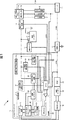
図1は、本発明を適用した車両の電気系統の一実施の形態を示すブロック図である。図1の電気系統1は、EV(Electric Vehicle、電気自動車),HEV(Hybrid Electric Vehicle、ハイブリッドカー)、PHEV(Plug-in Hybrid Electric Vehicle、プラグインハイブリッドカー)など、バッテリに蓄えられた電力を用いて走行する電動車両に設けられる電気系統のうち、主に低圧(例えば、12V)の電気部品(以下、低圧系負荷と称する)への電力の供給に関わる部分を示している。なお、低圧系負荷は、例えば、各種のECU(Electronic Control Unit)、パワーウインドウ用のモータ、照明ランプなどを含み、図1に示されるように、ACC(アクセサリ)負荷2、IG(イグニッション)負荷3、および、+B負荷4の3系統に分類される。また、以下、電気系統1が設けられている車両を自車と称する。
FIG. 1 is a block diagram showing an embodiment of an electric system of a vehicle to which the present invention is applied. The
電気系統1は、DCDCコンバータ11、低圧バッテリ12、温度センサ13、電流センサ回路14、低圧系J/B(Junction Box)15、低圧系電源ECU(Electronic Control Unit)16、スイッチ17、高圧バッテリ18、高圧系J/B(Junction Box)19、BMU(Battery Management Unit)20、および、車両ECU(Electronic Control Unit)21を含むように構成される。
The
DCDCコンバータ11は、電圧変換部31、出力電圧検出回路32、出力電流検出回路33、加熱保護温度センサ34、制御用自立電源回路35、および、制御部36を含むように構成される。
The
電圧変換部31は、制御部36の制御の基に、高圧系J/B19を介して高圧バッテリ18から供給される電力の電圧を変換し、低圧バッテリ12および低圧系J/B15に供給する。電圧変換部31は、フィルタ回路41、パワー素子フルブリッジ回路42、絶縁トランス43、および、整流平滑回路44を含むように構成される。
The
フィルタ回路41は、高圧系J/B19を介して高圧バッテリ18から供給される電圧のノイズを除去し、パワー素子フルブリッジ回路42に供給する。
The
パワー素子フルブリッジ回路42は、例えば、トランジスタ、MOSFET(Metal-Oxide-Semiconductor Field-Effect Transistor)、IGBT(Insulated Gate Bipolar Transistor)、IPM(Intelligent Power Module)などの電力用半導体スイッチング素子を用いたフルブリッジ回路により構成される。パワー素子フルブリッジ回路42は、制御部36のパルストランス回路54から供給されるスイッチング信号に基づいて、高圧系J/B19を介して高圧バッテリ18から供給される直流電圧を交流電圧に変換し、絶縁トランス43に供給する。
The power element
絶縁トランス43は、DCDCコンバータ11の入力と出力を絶縁するとともに、パワー素子フルブリッジ回路42から供給される交流電圧を所定の変圧比で変圧し、整流平滑回路44に供給する。
The insulating
整流平滑回路44の2つの出力端子のうち一方は、低圧バッテリ12の+端子、および、低圧系J/B15に接続され、他方は接地されている。整流平滑回路44は、絶縁トランス43から供給される交流電圧を直流電圧に整流および平滑化し、低圧バッテリ12および低圧系J/B15に供給する。
One of the two output terminals of the rectifying / smoothing circuit 44 is connected to the + terminal of the low-
出力電圧検出回路32は、DCDCコンバータ11の出力電圧を検出し、検出値を示す信号を制御部36のCPU51およびエラーアンプ52に供給する。
The output
出力電流検出回路33は、DCDCコンバータ11の出力電流を検出し、検出値を示す信号を制御部36のCPU51およびPWM IC53に供給する。
The output
加熱保護温度センサ34は、DCDCコンバータ11の温度を検出し、検出値を示す信号を制御部36のCPU51に供給する。
The heating
制御用自立電源回路35は、高圧系J/B19を介して高圧バッテリ18から供給される電力から、制御部36の駆動電力を生成し、制御部36に供給する。
The control self-supporting
制御部36は、CPU51、エラーアンプ52、PWM IC53、および、パルストランス回路54を含むように構成される。
The control unit 36 is configured to include a
CPU51は、温度センサ13から低圧バッテリ12の温度の検出値を示す信号を取得する。また、CPU51は、電流センサ回路14により検出される低圧系負荷への負荷電流の検出値を示す信号を取得する。CPU51は、DCDCコンバータ11の出力電圧、出力電流および温度、低圧バッテリ12の温度、並びに、自車の低圧系負荷への負荷電流に基づいて、DCDCコンバータ11の出力の開始および停止を制御したり、DCDCコンバータ11の出力電圧の目標値(以下、目標電圧と称する)を設定したりする。CPU51は、DCDCコンバータ11の目標電圧を示す信号をエラーアンプ52に供給する。
The
エラーアンプ52は、出力電圧検出回路32からの信号の値とCPU51からの信号の値の差分、すなわち、DCDCコンバータ11の出力電圧と目標電圧の差分を増幅し、PWM IC53に供給する。
The
PWM IC53は、エラーアンプ52から供給される信号に基づいて、DCDCコンバータ11の出力電圧が目標電圧となるように、パルストランス回路54に供給するPWM(Pulse Width Modulation)信号のデューティ比を制御するとともに、パルストランス回路54の出力の開始および停止を制御する。
The PWM IC 53 controls the duty ratio of a PWM (Pulse Width Modulation) signal supplied to the
パルストランス回路54は、PWM IC53からのPWM信号に基づくスイッチング信号をパワー素子フルブリッジ回路42に供給し、パワー素子フルブリッジ回路42のスイッチングを制御することにより、DCDCコンバータ11の出力電圧を制御する。
The
低圧バッテリ12は、高圧系J/B19およびDCDCコンバータ11を介して高圧バッテリ18から供給される電力により充電されるとともに、低圧系J/B15を介して、ACC負荷2、IG負荷3、および、+B4負荷に電力を供給する。なお、低圧バッテリ12の−端子は接地されている。
The
温度センサ13は、例えば、低圧バッテリ12のセルもしくは端子、または、低圧バッテリ12の近傍に設けられ、低圧バッテリ12の温度を検出する。温度センサ13は、低圧バッテリ12の温度の検出値を示す信号を、CAN(Controller Area Network)を介して、CPU51に供給する。
The
電流センサ回路14は、低圧バッテリ12と低圧系J/B15の間に設けられ、低圧系J/B15を介して、DCDCコンバータ11または低圧バッテリ12から低圧系負荷に供給される負荷電流を検出する。電流センサ回路14は、負荷電流の検出値を示す信号を、CANを介して、CPU51、車両ECU21およびBMU20に供給する。
The
低圧系J/B15は、例えば、コンタクタ、リレーなどを内蔵し、低圧系電源ECU16の制御の基に、ACC負荷2、IG負荷3、および、+B負荷4への電力の供給の有無を切替える。
The low-voltage system J /
スイッチ17は、例えば、イグニッションキースイッチもしくはスタータスイッチ、または、その両方により構成される。 The switch 17 includes, for example, an ignition key switch, a starter switch, or both.
例えば、走行用または高圧バッテリ18の充電用のエンジンを搭載するHEVまたはPHEVにより自車が構成される場合、スイッチ17は、例えば、LOCKまたはOFF(以下、OFFに統一する)、ACC(アクセサリ)、IG(イグニッション)またはON(以下、ONに統一する)、STARTの4つの位置に設定可能とされる。
For example, when the vehicle is composed of HEV or PHEV equipped with an engine for driving or charging the high-
この場合、スイッチ17の位置がOFFに設定されたとき、自車は、エンジンおよび主動力モータを稼動することができず、走行できない状態となる。また、自車は、低圧系電源ECU16の制御の基に、低圧系負荷のうち+B負荷4にのみ給電可能な状態となる。
In this case, when the position of the switch 17 is set to OFF, the host vehicle cannot operate the engine and the main power motor and cannot travel. In addition, the host vehicle can supply power only to the + B load 4 in the low-voltage system load under the control of the low-voltage system
また、スイッチ17の位置がACCに設定されたとき、OFFに設定されたときと同様に、自車は、エンジンおよび主動力モータを稼動することができず、走行できない状態となる。また、自車は、低圧系電源ECU16の制御の基に、低圧系負荷のうち+B負荷4およびACC負荷2に給電可能な状態となる。
Further, when the position of the switch 17 is set to ACC, as in the case where the switch 17 is set to OFF, the host vehicle cannot operate the engine and the main power motor and cannot travel. In addition, the host vehicle can supply power to the + B load 4 and the
さらに、スイッチ17の位置がONに設定されたとき、自車は、エンジンおよび主動力モータを稼動することができ、走行可能な状態となる。また、自車は、低圧系電源ECU16の制御の基に、+B負荷4、ACC負荷2およびIG負荷3の全ての低圧系負荷に給電可能な状態となる。
Further, when the position of the switch 17 is set to ON, the own vehicle can operate the engine and the main power motor, and is ready to travel. In addition, the host vehicle can supply power to all of the low-voltage loads of the + B load 4, the
また、スイッチ17の位置がSTARTに設定されたとき、自車のエンジンが点火し、始動する。また、自車は、低圧系電源ECU16の制御の基に、+B負荷4、ACC負荷2およびIG負荷3の全ての低圧系負荷に給電可能な状態となる。なお、車両の種類によっては、スイッチ17の位置がSTARTに設定された場合、セルフスタータモータを始動させるために、ACC負荷2への給電が停止される場合もある。
When the position of the switch 17 is set to START, the engine of the own vehicle is ignited and started. In addition, the host vehicle can supply power to all of the low-voltage loads of the + B load 4, the
このように、自車がHEVまたはPHEVにより構成される場合、電気系統1は、スイッチ17の設定位置に関わらず、+B負荷4に常時給電可能であり、スイッチ17の位置がACC、ONまたはSTARTに設定されたとき、ACC負荷2に給電可能となり、スイッチ17の位置がONまたはSTARTに設定されたとき、IG負荷3に給電可能となる。
Thus, when the own vehicle is configured by HEV or PHEV, the
また、例えば、エンジンを搭載しないEVにより自車が構成される場合、スイッチ17は、例えば、LOCKまたはOFF(以下、OFFに統一する)、ACC(アクセサリ)、STARTまたはON(以下、ONに統一する)の3つの位置に設定可能とされる。 For example, when the vehicle is composed of an EV not equipped with an engine, the switch 17 can be, for example, LOCK or OFF (hereinafter referred to as OFF), ACC (accessory), START or ON (hereinafter referred to as ON). Can be set at three positions.
この場合、スイッチ17の位置がOFFに設定されたとき、自車は、エンジンおよび主動力モータを稼動することができず、走行できない状態となる。また、自車は、低圧系電源ECU16の制御の基に、低圧系負荷のうち+B負荷4にのみ給電可能な状態となる。
In this case, when the position of the switch 17 is set to OFF, the host vehicle cannot operate the engine and the main power motor and cannot travel. In addition, the host vehicle can supply power only to the + B load 4 in the low-voltage system load under the control of the low-voltage system
また、スイッチ17の位置がACCに設定されたとき、OFFに設定されたときと同様に、自車は、エンジンおよび主動力モータを稼動することができず、走行できない状態となる。また、自車は、低圧系電源ECU16の制御の基に、低圧系負荷のうち+B負荷4およびACC負荷2に給電可能な状態となる。
Further, when the position of the switch 17 is set to ACC, as in the case where the switch 17 is set to OFF, the host vehicle cannot operate the engine and the main power motor and cannot travel. In addition, the host vehicle can supply power to the + B load 4 and the
さらに、スイッチ17の位置がONに設定されたとき、自車は、エンジンおよび主動力モータを稼動することができ、走行可能な状態となる。また、自車は、低圧系電源ECU16の制御の基に、+B負荷4、ACC負荷2およびIG負荷3の全ての低圧系負荷に給電可能な状態となる。
Further, when the position of the switch 17 is set to ON, the own vehicle can operate the engine and the main power motor, and is ready to travel. In addition, the host vehicle can supply power to all of the low-voltage loads of the + B load 4, the
このように、自車がEVにより構成される場合、電気系統1は、スイッチ17の設定位置に関わらず、+B負荷4に常時給電可能であり、スイッチ17の位置がACCまたはONに設定されたとき、ACC負荷2に給電可能となり、スイッチ17の位置がONに設定されたとき、IG負荷3に給電可能となる。
Thus, when the own vehicle is configured by EV, the
なお、IG負荷3に給電可能な状態において、低圧系J/B15からDCDCコンバータ11のCPU51に制御信号および電力の供給を行うことが可能である。DCDCコンバータ11は、この制御信号をトリガにして、低圧系J/Bから供給される電力を用いて起動し、出力を開始することが可能である。
In a state where power can be supplied to the IG load 3, it is possible to supply a control signal and power from the low voltage system J /
そして、スイッチ17は、スイッチ17の設定位置を示す信号を、CANを介して、低圧系電源ECU16および車両ECU21に供給する。
The switch 17 supplies a signal indicating the set position of the switch 17 to the low-voltage
高圧バッテリ18は、自車の動力源として用いられる。具体的には、高圧バッテリ18に蓄えられている電力は、高圧系J/B19を介して、図示せぬ走行系インバータに供給され、直流電力から交流電力に変換される。そして、その交流電力が図示せぬ主動力モータに供給され、主動力モータが駆動されることにより、自車が走行する。また、高圧バッテリ18は、高圧系J/B19を介して、主動力モータ以外の自車の高圧系負荷にも電力を供給する。
The
高圧系J/B19は、例えば、コンタクタ、リレーなどを内蔵し、図示せぬECUの制御の基に、DCDCコンバータ11、および、自車の高圧系負荷への電力の供給の有無を切替える。
The high-voltage system J /
BMU20は、高圧バッテリ18の管理を行う。例えば、BMU20は、高圧バッテリ18の状態(例えば、電圧、電流、温度など)を監視し、監視結果を示す情報を、CANを介して、CPU51および車両ECU21に供給する。
The
車両ECU21は、図示せぬ走行系インバータなどの制御を行う。また、CPU51と車両ECU21とは、CANを介して通信し、各種の制御情報の送受信を行う。
The vehicle ECU 21 controls a travel system inverter (not shown). In addition, the
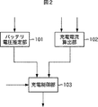
図2は、DCDCコンバータ11のCPU51が所定の制御プログラムを実行することにより実現される機能の構成の例の一部を示すブロック図である。CPU51が所定の制御プログラムを実行することにより、バッテリ電圧推定部101、充電電流算出部102、および、充電制御部103を含む機能が実現される。
FIG. 2 is a block diagram showing a part of an example of a functional configuration realized by the
バッテリ電圧推定部101は、図3を参照して後述するように、出力電圧検出回路32からの信号に示される電圧に基づいて、低圧バッテリ12の電圧(例えば、+端子と−端子間の電圧)を推定する。バッテリ電圧推定部101は、推定した低圧バッテリ12の電圧を示す情報を充電制御部103に供給する。
As will be described later with reference to FIG. 3, the battery
充電電流算出部102は、図3を参照して後述するように、出力電流検出回路33からの信号に示されるDCDCコンバータ11の出力電流、および、電流センサ回路14からの信号に示される低圧系負荷の負荷電流に基づいて、低圧バッテリ12の充電電流を算出する。充電電流算出部102は、算出した充電電流を示す情報を充電制御部103に供給する。
As will be described later with reference to FIG. 3, the charging
充電制御部103は、図3を参照して後述するように、温度センサ13からの信号により示される低圧バッテリ12の温度に基づいて、DCDCコンバータ11の出力の開始および停止を制御する。さらに、充電制御部103は、図3を参照して後述するように、バッテリ電圧推定部101により推定された低圧バッテリ12の電圧、および、充電電流算出部102により算出された低圧バッテリ12の充電電流に基づいて、DCDCコンバータ11の目標電圧を設定し、設定した目標電圧を示す信号をエラーアンプ52に供給する。
As will be described later with reference to FIG. 3, the charging
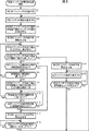
次に、図3のフローチャートを参照して、自車の電気系統1により実行される低圧バッテリ充電制御処理について説明する。なお、この処理は、例えば、スイッチ17がイグニッションキースイッチにより構成される場合、スイッチ17の位置がLOCK以外の位置に設定されたとき開始され、LOCKに設定されたとき終了する。または、この処理は、例えば、スイッチ17がスタータスイッチにより構成される場合、スイッチ17の位置が、OFF以外の位置に設定されたとき開始され、OFFに設定されたとき終了する。
Next, the low-voltage battery charging control process executed by the
ステップS1において、DCDCコンバータ11が起動する。具体的には、高圧系J/B19は、スイッチ17の位置がLOCKまたはOFF以外の位置に設定されたのに伴い、図示せぬECUの制御の基に、DCDCコンバータ11への高圧バッテリ18の電力の供給を開始する。これにより、制御用自立電源回路35から制御部36への電力の供給が開始され、DCDCコンバータ11が起動する。
In step S1, the
ステップS2において、バッテリ電圧推定部101は、低圧バッテリ12の電圧を推定する。具体的には、バッテリ電圧推定部101は、出力電圧検出回路32からの信号に示される現在の電圧、すなわち、出力停止時のDCDCコンバータ11の出力側の電圧から、DCDCコンバータ11と低圧バッテリ12との間の降下電圧を差し引くことにより、低圧バッテリ12の電圧を推定する。なお、DCDCコンバータ11と低圧バッテリ12との間の降下電圧は、DCDCコンバータ11と低圧バッテリ12との間の回路抵抗などに基づいて、予め求められている。バッテリ電圧推定部101は、推定した低圧バッテリ12の電圧を示す情報を充電制御部103に供給する。
In step S <b> 2, the battery
ステップS3において、制御部36は、DCDCコンバータ11の出力電圧を現在の低圧バッテリ12の電圧に設定する。具体的には、充電制御部103は、バッテリ電圧推定部101により推定された低圧バッテリ12の電圧と同じ値にDCDCコンバータ11の目標電圧を設定する。充電制御部103は、設定した目標電圧を示す信号のエラーアンプ52への供給を開始する。PWM IC53は、パルストランス回路54へのPWM信号の供給を開始するとともに、エラーアンプ52から供給される信号に基づいて、DCDCコンバータ11の出力電圧が目標電圧となるようにPWM信号のデューティ比を制御する。
In step S <b> 3, the control unit 36 sets the output voltage of the
ステップS4において、制御部36は、DCDCコンバータ11の出力を開始させる。具体的には、パルストランス回路54は、PWM IC53の制御の基に、PWM IC53からのPWM信号に基づくスイッチング信号のパワー素子フルブリッジ回路42への供給を開始する。これにより、パワー素子フルブリッジ回路42が起動し、DCDCコンバータ11の出力が開始され、DCDCコンバータ11から低圧バッテリ12への充電電流の供給が開始される。
In step S <b> 4, the control unit 36 starts the output of the
なお、このとき、DCDCコンバータ11の出力電圧は、バッテリ電圧推定部101により推定された低圧バッテリ12の電圧と等しくなるように制御される。従って、DCDCコンバータ11の出力開始時に、DCDCコンバータ11から低圧バッテリ12に過大な突入電流が流れることが防止される。
At this time, the output voltage of the
ステップS5において、制御部36は、DCDCコンバータ11の出力電圧をΔV(例えば、0.1V)だけ上昇させる。具体的には、充電制御部103は、出力電圧検出回路32からの信号に示される現在のDCDCコンバータ11の出力電圧にΔVを加算した値に、目標電圧を変更する。充電制御部103は、変更した目標電圧を示す信号のエラーアンプ52への供給を開始する。これにより、DCDCコンバータ11の出力電圧が、現在の出力電圧からΔVだけ上昇するように制御される。
In step S5, the control unit 36 increases the output voltage of the
なお、ΔVは、DCDCコンバータ11から低圧バッテリ12に供給される充電電流が、所定の規定値(例えば、低圧バッテリ12の5時間放電率の電流(5時間率電流))を超えないように、DCDCコンバータ11の出力電圧を徐変制御するために、予め設定される値である。
Note that ΔV is such that the charging current supplied from the
ステップS6において、充電制御部103は、出力電圧検出回路32からの信号に基づいて、DCDCコンバータ11の出力電圧が充電終了電圧(例えば、14V)に達したか否かを判定する。DCDCコンバータ11の出力電圧が、まだ充電終了電圧に達していないと判定された場合、処理はステップS7に進む。なお、充電終了電圧は、例えば、低圧バッテリ12の充電終止電圧に、DCDCコンバータ11と低圧バッテリ12との間の降下電圧を加算した値に設定される。
In step S <b> 6, the charging
ステップS7において、充電制御部103は、低圧バッテリ12の温度変化率が規定値を超えたか否かを判定する。具体的には、充電制御部103は、温度センサ13からの信号に示される現在の低圧バッテリ12の温度と、所定の時間Δt前(例えば、1分前)の低圧バッテリ12の温度との差分を求める。充電制御部103は、求めた差分値が所定の規定値を超えていない場合、低圧バッテリ12の温度変化率が規定値を超えていないと判定し、処理はステップS8に進む。
In step S <b> 7, the charging
ステップS8において、充電制御部103は、充電電流が既定値に達しか否かを判定する。具体的には、充電電流算出部102は、出力電流検出回路33からの信号に示される現在のDCDCコンバータ11の出力電流から、電流センサ回路14からの信号に示される現在の低圧系負荷の負荷電流を差し引くことにより、現在の低圧バッテリ12の充電電流を算出する。これにより、DCDCコンバータ11の出力電流のみを検出する場合と比較して、低圧バッテリ12の充電電流をより正確に検出することができる。充電電流算出部102は、算出した低圧バッテリ12の充電電流を示す信号を充電制御部103に供給する。充電制御部103が、充電電流算出部102により算出された充電電流が、規定値(例えば、上述した低圧バッテリ12の5時間率電流)に達していないと判定した場合、処理はステップS5に戻る。
In step S8, the charging
その後、ステップS6において、DCDCコンバータ11の出力電圧が充電終了電圧に達したと判定されるか、ステップS7において、低圧バッテリ12の温度変化率が規定値を超えたと判定されるか、ステップS8において、充電電流が規定値に達したと判定されるまで、ステップS5乃至S8の処理が繰り返し実行される。
Thereafter, in step S6, it is determined that the output voltage of the
一方、ステップS8において、充電電流が規定値に達したと判定された場合、処理はステップS9に進む。 On the other hand, if it is determined in step S8 that the charging current has reached the specified value, the process proceeds to step S9.
ステップS9において、制御部36は、DCDCコンバータ11の出力電圧を充電電流が規定値に達したときの値に固定する。具体的には、充電制御部103は、出力電圧検出回路32からの信号に示される現在のDCDCコンバータ11の出力電圧、すなわち、充電電流が規定値に達したときの出力電圧に、DCDCコンバータ11の目標電圧を変更する。充電制御部103は、変更した目標電圧を示す信号のエラーアンプ52への供給を開始する。これにより、DCDCコンバータ11の出力電圧が、ステップS8において充電電流が規定値に達したと判定されたときの電圧に固定されるように制御される。そして、DCDCコンバータ11の出力電圧が固定されることにより、低圧バッテリ12の電圧が上昇するにつれて、低圧バッテリ12の充電電流が徐々に低下していく。
In step S9, the control unit 36 fixes the output voltage of the
ステップS10において、充電制御部103は、充電電流が所定の閾値未満になったか否かを判定する。具体的には、充電電流算出部102は、ステップS8と同様の処理により、低圧バッテリ12の充電電流を算出し、算出した充電電流を示す情報を充電制御部103に供給する。充電制御部103が、充電電流算出部102により算出された充電電流が所定の閾値未満になっていないと判定した場合、処理はステップS11に進む。なお、この閾値は、例えば、上述した充電電流の規定値より所定の値だけ低い電流に設定される。
In step S10, the charging
ステップS11において、ステップS7の処理と同様に、低圧バッテリ12の温度変化率が規定値を超えたか否かが判定される。低圧バッテリ12の温度変化率が規定値を超えていないと判定された場合、処理はステップS10に戻る。
In step S11, it is determined whether or not the temperature change rate of the low-
その後、ステップS10において、充電電流が所定の閾値未満になったと判定されるか、ステップS11において、低圧バッテリ12の温度変化率が規定値を超えたと判定されるまで、ステップS10およびS11の処理が繰り返し実行される。
Thereafter, the processes in steps S10 and S11 are performed until it is determined in step S10 that the charging current has become less than a predetermined threshold value, or in step S11, it is determined that the temperature change rate of the low-
一方、ステップS10において、充電電流が所定の閾値未満になったと判定された場合、処理はステップS5に戻る。その後、ステップS6において、DCDCコンバータ11の出力電圧が充電終了電圧に達したと判定されるか、ステップS7またはステップS11において、低圧バッテリ12の温度変化率が規定値を超えたと判定されるまで、ステップS5乃至S11の処理が繰り返し実行される。
On the other hand, if it is determined in step S10 that the charging current has become less than the predetermined threshold, the process returns to step S5. Thereafter, until it is determined in step S6 that the output voltage of the
一方、ステップS7またはステップS11において、低圧バッテリ12の温度変化率が規定値を超えたと判定された場合、処理はステップS12に進む。
On the other hand, if it is determined in step S7 or step S11 that the temperature change rate of the
ステップS12において、制御部36は、DCDCコンバータ11の出力を停止させる。具体的には、充電制御部103は、目標電圧を示す信号のエラーアンプ52への供給を停止する。これにより、PWM IC53からパルストランス回路54へのPWM信号の供給が停止され、DCDCコンバータ11の出力が停止する。
In step S <b> 12, the control unit 36 stops the output of the
ステップS13において、充電制御部103は、低圧バッテリ12の温度が規定温度以下になったか否かを判定する。充電制御部103は、所定の間隔で、温度センサ13からの信号に基づいて、低圧バッテリ12の温度が規定温度以下になったか否かを判定し、低圧バッテリ12の温度が規定温度以下になるまで待機する。そして、低圧バッテリ12の温度が規定温度以下になったとき、処理はステップS2に戻り、ステップS2以降の処理が実行される。すなわち、低圧バッテリ12の充電が再開される。
In step S13, the charging
これにより、充放電や低圧バッテリ12の周囲の温度などの要因により、低圧バッテリ12の内部抵抗が上昇し、充電電力の損失が大きくなっているときに低圧バッテリ12の充電を継続して、充電効率が悪化することが防止される。
As a result, due to factors such as charging / discharging and the ambient temperature of the low-
一方、ステップS6において、DCDCコンバータ11の出力電圧が充電終了電圧に達したと判定された場合、処理はステップS14に進む。
On the other hand, if it is determined in step S6 that the output voltage of the
ステップS14において、ステップS12の処理と同様に、DCDCコンバータ11の出力が停止される。
In step S14, the output of the
ステップS15において、ステップS2の処理と同様に、低圧バッテリ12の電圧が推定される。
In step S15, the voltage of the
ステップS16において、充電制御部103は、ステップS15の処理の結果に基づいて、低圧バッテリ12の電圧が充電開始電圧以下であるか否かが判定される。低圧バッテリ12の電圧が充電開始電圧以下でないと判定された場合、処理はステップS15に戻る。その後、ステップS16において、低圧バッテリ12の電圧が充電開始電圧以下であると判定されるまで、ステップS15およびS16の処理が繰り返し実行される。
In step S16, the charging
一方、ステップS16において、低圧バッテリ12の電圧が充電開始電圧以下であると判定された場合、処理はステップS2に戻り、ステップS2以降の処理が実行される。すなわち、低圧バッテリ12の電圧が充電開始電圧以下になったとき、低圧バッテリ12の充電が開始される。なお、充電開始電圧は、例えば、低圧バッテリ12の放電終止電圧、または、低圧系負荷の駆動電圧の最小値付近の電圧に設定される。
On the other hand, when it is determined in step S16 that the voltage of the
なお、スイッチ17の位置がLOCKまたはOFF以外の位置に設定されたとき、高圧系J/B19は、図示せぬECUの制御の基に、DCDCコンバータ11への高圧バッテリ18の電力の供給を停止し、DCDCコンバータ11が停止し、低圧バッテリ充電制御処理は終了する。
When the position of the switch 17 is set to a position other than LOCK or OFF, the high voltage system J /
以上のようにして、充電電流が規定値を超えたり、充電電流が不足したりしないように、DCDCコンバータ11の出力電圧が、充電開始時の低圧バッテリ12の電圧から充電終了電圧までΔVずつ上昇されるとともに、低圧バッテリ12の温度に基づいて充電効率が低下することが防止され、適切に低圧バッテリ12が充電される。
As described above, the output voltage of the
なお、以上の説明では、DCDCコンバータ11内に制御部36を設ける例を示したが、制御部36とDCDCコンバータ11を分離して設けるようにしてもよい。あるいは、例えば、CPU51だけDCDCコンバータ11から分離して設けるようにしてもよい。
In the above description, the example in which the control unit 36 is provided in the
また、低圧バッテリ12の電圧の測定方法として、例えば、充電電流が0AになるようにDCDCコンバータ11の出力電圧を制御し、そのときの出力電圧を、低圧バッテリの電圧として測定するようにしてもよい。
Further, as a method for measuring the voltage of the
さらに、以上の説明では、低圧バッテリ12の温度変化率が規定値を超えた場合に、DCDCコンバータ11の出力を停止するようにしたが、DCDCコンバータ11の出力電流、すなわち、低圧バッテリ12の充電電流を下げるようにしてもよい。
Furthermore, in the above description, when the temperature change rate of the low-
また、上述した一連のCPU51の処理は、ハードウエアにより実行するようにすることも可能である。
The series of processes of the
さらに、CPU51が実行する制御プログラムは、例えば、予めDCDCコンバータ11の図示せぬ記録媒体にインストールしておくことも可能であるし、または、例えば、磁気ディスク(フレキシブルディスクを含む)、光ディスク(CD-ROM(Compact Disc-Read Only Memory),DVD(Digital Versatile Disc)等)、光磁気ディスク、もしくは半導体メモリなどよりなるパッケージメディアであるリムーバブルメディアに記録して、あるいは、ローカルエリアネットワーク、インターネット、デジタル衛星放送といった、有線または無線の伝送媒体を介して提供し、インストールすることも可能である。
Furthermore, the control program executed by the
また、CPU51が実行するプログラムは、本明細書で説明する順序に沿って時系列に処理が行われるプログラムであっても良いし、並列に、あるいは呼び出しが行われたとき等の必要なタイミングで処理が行われるプログラムであっても良い。
The program executed by the
さらに、本発明の実施の形態は、上述した実施の形態に限定されるものではなく、本発明の要旨を逸脱しない範囲において種々の変更が可能である。 Furthermore, the embodiments of the present invention are not limited to the above-described embodiments, and various modifications can be made without departing from the gist of the present invention.
1 電気系統
2 ACC負荷
3 IG負荷
4 +B負荷
11 DCDCコンバータ
12 低圧バッテリ
13 温度センサ
14 電流センサ回路
18 高圧バッテリ
31 電圧変換部
32 出力電圧検出回路
33 出力電流検出回路
36 制御部
41 フィルタ回路
42 パワー素子フルブリッジ回路
43 絶縁トランス
44 整流平滑回路
51 CPU
52 エラーアンプ
53 PWM IC
54 パルストランス回路
101 バッテリ電圧推定部
102 充電電流算出部
103 充電制御部
DESCRIPTION OF
52 Error Amplifier 53 PWM IC
54
Claims (6)
前記電圧変換部の出力電流および前記電気部品への負荷電流に基づいて、前記第2のバッテリの充電電流を算出する充電電流算出手段と、
前記充電電流が規定の電流を超えないように前記電圧変換部の出力電圧を制御する充電制御手段と
を含む充電制御装置。 Controlling charging of a second battery that supplies power to an electrical component provided in the vehicle, which is charged by power obtained by converting the power of a first battery, which is a power source of the vehicle, by a voltage conversion unit. In the charge control device,
Charging current calculation means for calculating a charging current of the second battery based on an output current of the voltage converter and a load current to the electrical component;
And a charge control means for controlling an output voltage of the voltage converter so that the charge current does not exceed a specified current.
さらに含み、
前記充電制御手段は、推定された前記第2のバッテリの電圧から規定の電圧まで、前記電圧変換部の出力電圧を所定の値ずつ上昇させる
請求項1に記載の充電制御装置。 Battery voltage estimation for estimating the voltage of the second battery based on the voltage on the output side when the output of the voltage conversion unit is stopped and the known voltage drop between the voltage conversion unit and the second battery Further comprising means,
The charge control device according to claim 1, wherein the charge control unit increases the output voltage of the voltage conversion unit by a predetermined value from the estimated voltage of the second battery to a specified voltage.
請求項1に記載の充電制御装置。 The charge control unit stops the output of the voltage conversion unit until the temperature of the second battery becomes equal to or lower than a predetermined temperature when the temperature change rate of the second battery exceeds a specified value. The charging control device according to 1.
前記電圧変換部の出力電流および前記電気部品への負荷電流に基づいて、前記第2のバッテリの充電電流を算出し、
前記充電電流が規定の電流を超えないように前記電圧変換部の出力電圧を制御する
ステップを含む充電制御装置。 Controlling charging of a second battery that supplies power to an electrical component provided in the vehicle, which is charged by power obtained by converting the power of a first battery, which is a power source of the vehicle, by a voltage conversion unit. The charge control device
Based on the output current of the voltage converter and the load current to the electrical component, the charging current of the second battery is calculated,
A charge control device including a step of controlling an output voltage of the voltage converter so that the charge current does not exceed a specified current.
前記電圧変換部の出力電流および前記電気部品への負荷電流に基づいて、前記第2のバッテリの充電電流を算出し、
前記充電電流が規定の電流を超えないように前記電圧変換部の出力電圧を制御する
ステップを含む処理を実行させるプログラム。 Controlling charging of a second battery that supplies power to an electrical component provided in the vehicle, which is charged by power obtained by converting the power of a first battery, which is a power source of the vehicle, by a voltage conversion unit. On the computer,
Based on the output current of the voltage converter and the load current to the electrical component, the charging current of the second battery is calculated,
The program which performs the process including the step which controls the output voltage of the said voltage conversion part so that the said charging current may not exceed a regulation current.
前記第1のバッテリの電圧を変換して前記第2のバッテリに供給する電圧変換手段と、
前記電圧変換手段の出力電流を検出する出力電流検出手段と、
前記出力電流検出手段により検出された前記電圧変換手段の出力電流、および、前記電気部品への負荷電流を検出する負荷電流検出部により検出された前記電気部品への負荷電流に基づいて、前記第2のバッテリの充電電流を算出する充電電流算出手段と、
前記充電電流が規定の電流を超えないように前記電圧変換手段の出力電圧を制御する充電制御手段と
を含む充電装置。 In a charging device for charging a second battery that supplies electric power to an electrical component provided in the vehicle, using electric power of a first battery that is a power source of the vehicle,
Voltage conversion means for converting the voltage of the first battery and supplying the voltage to the second battery;
Output current detection means for detecting the output current of the voltage conversion means;
Based on the output current of the voltage conversion means detected by the output current detection means and the load current to the electrical component detected by a load current detection unit for detecting the load current to the electrical component, the first Charging current calculating means for calculating the charging current of the battery of 2;
And a charging control means for controlling an output voltage of the voltage converting means so that the charging current does not exceed a specified current.
Priority Applications (1)
| Application Number | Priority Date | Filing Date | Title |
|---|---|---|---|
| JP2009043959A JP2010200529A (en) | 2009-02-26 | 2009-02-26 | Apparatus and method for charging control, charging device, and program |
Applications Claiming Priority (1)
| Application Number | Priority Date | Filing Date | Title |
|---|---|---|---|
| JP2009043959A JP2010200529A (en) | 2009-02-26 | 2009-02-26 | Apparatus and method for charging control, charging device, and program |
Publications (1)
| Publication Number | Publication Date |
|---|---|
| JP2010200529A true JP2010200529A (en) | 2010-09-09 |
Family
ID=42824642
Family Applications (1)
| Application Number | Title | Priority Date | Filing Date |
|---|---|---|---|
| JP2009043959A Withdrawn JP2010200529A (en) | 2009-02-26 | 2009-02-26 | Apparatus and method for charging control, charging device, and program |
Country Status (1)
| Country | Link |
|---|---|
| JP (1) | JP2010200529A (en) |
Cited By (8)
| Publication number | Priority date | Publication date | Assignee | Title |
|---|---|---|---|---|
| WO2013129231A1 (en) * | 2012-02-27 | 2013-09-06 | 日産自動車株式会社 | Power supply apparatus |
| US9180785B2 (en) | 2013-04-11 | 2015-11-10 | Hyundai Motor Company | System and method of controlling low-voltage DC/DC converter for electric vehicle |
| JP2016005407A (en) * | 2014-06-18 | 2016-01-12 | 株式会社Nttドコモ | Power control unit and power control method |
| WO2016009476A1 (en) * | 2014-07-14 | 2016-01-21 | 本田技研工業株式会社 | Power system |
| DE102018211302A1 (en) | 2017-07-13 | 2019-01-17 | Suzuki Motor Corporation | power converter |
| CN112234819A (en) * | 2020-10-14 | 2021-01-15 | 睿驰电装(大连)电动系统有限公司 | Low-voltage power supply method, device and electronic device based on DC-DC |
| WO2021179367A1 (en) * | 2020-03-10 | 2021-09-16 | 浙江禾川科技股份有限公司 | Performance test method, apparatus and device for power-on snubber resistor |
| WO2023160477A1 (en) * | 2022-02-28 | 2023-08-31 | 北京车和家汽车科技有限公司 | Voltage control method and apparatus |
-
2009
- 2009-02-26 JP JP2009043959A patent/JP2010200529A/en not_active Withdrawn
Cited By (13)
| Publication number | Priority date | Publication date | Assignee | Title |
|---|---|---|---|---|
| WO2013129231A1 (en) * | 2012-02-27 | 2013-09-06 | 日産自動車株式会社 | Power supply apparatus |
| US9180785B2 (en) | 2013-04-11 | 2015-11-10 | Hyundai Motor Company | System and method of controlling low-voltage DC/DC converter for electric vehicle |
| JP2016005407A (en) * | 2014-06-18 | 2016-01-12 | 株式会社Nttドコモ | Power control unit and power control method |
| WO2016009476A1 (en) * | 2014-07-14 | 2016-01-21 | 本田技研工業株式会社 | Power system |
| JPWO2016009476A1 (en) * | 2014-07-14 | 2017-04-27 | 本田技研工業株式会社 | Power system |
| US9776622B2 (en) | 2014-07-14 | 2017-10-03 | Honda Motor Co., Ltd. | Power system |
| DE102018211302A1 (en) | 2017-07-13 | 2019-01-17 | Suzuki Motor Corporation | power converter |
| FR3069109A1 (en) | 2017-07-13 | 2019-01-18 | Suzuki Motor Corporation | POWER CONVERTER |
| WO2021179367A1 (en) * | 2020-03-10 | 2021-09-16 | 浙江禾川科技股份有限公司 | Performance test method, apparatus and device for power-on snubber resistor |
| CN112234819A (en) * | 2020-10-14 | 2021-01-15 | 睿驰电装(大连)电动系统有限公司 | Low-voltage power supply method, device and electronic device based on DC-DC |
| CN112234819B (en) * | 2020-10-14 | 2022-02-01 | 睿驰电装(大连)电动系统有限公司 | Low-voltage power supply method and device based on DC-DC and electronic equipment |
| WO2023160477A1 (en) * | 2022-02-28 | 2023-08-31 | 北京车和家汽车科技有限公司 | Voltage control method and apparatus |
| EP4468553A4 (en) * | 2022-02-28 | 2025-05-21 | Beijing Chehejia Automobile Technology Co., Ltd. | Method and device for voltage control |
Similar Documents
| Publication | Publication Date | Title |
|---|---|---|
| US20100244782A1 (en) | Charging control device and method, charging device, as well as program | |
| US7023107B2 (en) | Power circuit for battery | |
| US10988043B2 (en) | Vehicle and method of charging electric power storage device | |
| US8248033B2 (en) | Secondary battery temperature-increasing control apparatus and vehicle including the same, and secondary battery temperature-increasing control method | |
| JP2010200529A (en) | Apparatus and method for charging control, charging device, and program | |
| US8437910B2 (en) | Automotive electric power supply system | |
| US9071081B2 (en) | Power source device for vehicle | |
| US9156466B2 (en) | Method and apparatus for power management of an electric drive for a hybrid vehicle | |
| CN102403891B (en) | Dc-dc converter | |
| US10640003B2 (en) | Double-pulse test systems and methods | |
| JP5247520B2 (en) | Power control apparatus and method, and program | |
| JP7178892B2 (en) | vehicle battery charging controller | |
| CN110014935B (en) | Method for charging a battery of an electric vehicle | |
| CN113711457A (en) | Conversion device, conversion system, switching device, vehicle including these devices, and control method | |
| CN107852010B (en) | Storage battery control device | |
| JP2012039778A (en) | Dc/dc converter | |
| JP6056486B2 (en) | Vehicle power supply device | |
| JP2010206886A (en) | Power control apparatus, method, and program | |
| KR102213262B1 (en) | LDC control device for protecting overheat of LDC and method thereof | |
| US20210261018A1 (en) | Vehicle power supply device | |
| JP2010200531A (en) | Device and method for diagnosis of battery, and program | |
| KR20140068556A (en) | Control method of DC-DC converter for electric vehicle | |
| KR101370739B1 (en) | Convertor for electric vehicle, electric vehicle including the same, and method for controlling the same | |
| KR100992762B1 (en) | Life Prediction Device and Method of Low Voltage DC Converter | |
| JP2020145817A (en) | Voltage conversion device |
Legal Events
| Date | Code | Title | Description |
|---|---|---|---|
| A711 | Notification of change in applicant |
Free format text: JAPANESE INTERMEDIATE CODE: A712 Effective date: 20100727 |
|
| A300 | Withdrawal of application because of no request for examination |
Free format text: JAPANESE INTERMEDIATE CODE: A300 Effective date: 20120501 |