JP5247460B2 - Microchip - Google Patents
Microchip Download PDFInfo
- Publication number
- JP5247460B2 JP5247460B2 JP2008542054A JP2008542054A JP5247460B2 JP 5247460 B2 JP5247460 B2 JP 5247460B2 JP 2008542054 A JP2008542054 A JP 2008542054A JP 2008542054 A JP2008542054 A JP 2008542054A JP 5247460 B2 JP5247460 B2 JP 5247460B2
- Authority
- JP
- Japan
- Prior art keywords
- cavity
- capillary
- capillary cavity
- microchip
- sample liquid
- Prior art date
- Legal status (The legal status is an assumption and is not a legal conclusion. Google has not performed a legal analysis and makes no representation as to the accuracy of the status listed.)
- Active
Links
- 239000007788 liquid Substances 0.000 claims description 111
- 239000000523 sample Substances 0.000 claims description 103
- 239000012488 sample solution Substances 0.000 claims description 40
- 230000002093 peripheral effect Effects 0.000 claims description 39
- 238000004891 communication Methods 0.000 claims description 3
- 230000005661 hydrophobic surface Effects 0.000 claims description 3
- 238000005259 measurement Methods 0.000 description 53
- 238000009826 distribution Methods 0.000 description 38
- 238000000034 method Methods 0.000 description 20
- 239000000758 substrate Substances 0.000 description 17
- 238000002347 injection Methods 0.000 description 15
- 239000007924 injection Substances 0.000 description 15
- 239000003153 chemical reaction reagent Substances 0.000 description 13
- 238000012546 transfer Methods 0.000 description 11
- 238000004458 analytical method Methods 0.000 description 9
- 239000000243 solution Substances 0.000 description 9
- 238000007599 discharging Methods 0.000 description 8
- 230000000694 effects Effects 0.000 description 7
- 239000003085 diluting agent Substances 0.000 description 6
- 230000003287 optical effect Effects 0.000 description 6
- 238000010586 diagram Methods 0.000 description 5
- 238000002835 absorbance Methods 0.000 description 4
- 210000004369 blood Anatomy 0.000 description 4
- 239000008280 blood Substances 0.000 description 4
- 238000005429 filling process Methods 0.000 description 4
- 238000002156 mixing Methods 0.000 description 4
- 239000000203 mixture Substances 0.000 description 4
- 239000007787 solid Substances 0.000 description 4
- 238000004381 surface treatment Methods 0.000 description 4
- WQZGKKKJIJFFOK-GASJEMHNSA-N Glucose Natural products OC[C@H]1OC(O)[C@H](O)[C@@H](O)[C@@H]1O WQZGKKKJIJFFOK-GASJEMHNSA-N 0.000 description 3
- 239000013060 biological fluid Substances 0.000 description 3
- 210000004027 cell Anatomy 0.000 description 3
- 239000008103 glucose Substances 0.000 description 3
- 238000012545 processing Methods 0.000 description 3
- XLYOFNOQVPJJNP-UHFFFAOYSA-N water Substances O XLYOFNOQVPJJNP-UHFFFAOYSA-N 0.000 description 3
- PXGOKWXKJXAPGV-UHFFFAOYSA-N Fluorine Chemical compound FF PXGOKWXKJXAPGV-UHFFFAOYSA-N 0.000 description 2
- CBENFWSGALASAD-UHFFFAOYSA-N Ozone Chemical compound [O-][O+]=O CBENFWSGALASAD-UHFFFAOYSA-N 0.000 description 2
- 230000001133 acceleration Effects 0.000 description 2
- HVYWMOMLDIMFJA-DPAQBDIFSA-N cholesterol Chemical compound C1C=C2C[C@@H](O)CC[C@]2(C)[C@@H]2[C@@H]1[C@@H]1CC[C@H]([C@H](C)CCCC(C)C)[C@@]1(C)CC2 HVYWMOMLDIMFJA-DPAQBDIFSA-N 0.000 description 2
- 238000009792 diffusion process Methods 0.000 description 2
- 239000012530 fluid Substances 0.000 description 2
- 229910052731 fluorine Inorganic materials 0.000 description 2
- 239000011737 fluorine Substances 0.000 description 2
- 229920001477 hydrophilic polymer Polymers 0.000 description 2
- 239000000463 material Substances 0.000 description 2
- 239000004094 surface-active agent Substances 0.000 description 2
- 108010015776 Glucose oxidase Proteins 0.000 description 1
- 239000004366 Glucose oxidase Substances 0.000 description 1
- 102000001554 Hemoglobins Human genes 0.000 description 1
- 108010054147 Hemoglobins Proteins 0.000 description 1
- WQZGKKKJIJFFOK-VFUOTHLCSA-N beta-D-glucose Chemical compound OC[C@H]1O[C@@H](O)[C@H](O)[C@@H](O)[C@@H]1O WQZGKKKJIJFFOK-VFUOTHLCSA-N 0.000 description 1
- 210000000601 blood cell Anatomy 0.000 description 1
- 238000005119 centrifugation Methods 0.000 description 1
- 235000012000 cholesterol Nutrition 0.000 description 1
- 230000001086 cytosolic effect Effects 0.000 description 1
- 210000003743 erythrocyte Anatomy 0.000 description 1
- 238000001914 filtration Methods 0.000 description 1
- -1 for example Substances 0.000 description 1
- 230000006870 function Effects 0.000 description 1
- 229940116332 glucose oxidase Drugs 0.000 description 1
- 235000019420 glucose oxidase Nutrition 0.000 description 1
- 238000005534 hematocrit Methods 0.000 description 1
- 230000002209 hydrophobic effect Effects 0.000 description 1
- 150000002632 lipids Chemical class 0.000 description 1
- 238000004204 optical analysis method Methods 0.000 description 1
- 238000005070 sampling Methods 0.000 description 1
- 238000000926 separation method Methods 0.000 description 1
- 238000003756 stirring Methods 0.000 description 1
Images


Classifications
-
- B—PERFORMING OPERATIONS; TRANSPORTING
- B01—PHYSICAL OR CHEMICAL PROCESSES OR APPARATUS IN GENERAL
- B01L—CHEMICAL OR PHYSICAL LABORATORY APPARATUS FOR GENERAL USE
- B01L3/00—Containers or dishes for laboratory use, e.g. laboratory glassware; Droppers
- B01L3/50—Containers for the purpose of retaining a material to be analysed, e.g. test tubes
- B01L3/502—Containers for the purpose of retaining a material to be analysed, e.g. test tubes with fluid transport, e.g. in multi-compartment structures
- B01L3/5027—Containers for the purpose of retaining a material to be analysed, e.g. test tubes with fluid transport, e.g. in multi-compartment structures by integrated microfluidic structures, i.e. dimensions of channels and chambers are such that surface tension forces are important, e.g. lab-on-a-chip
- B01L3/502715—Containers for the purpose of retaining a material to be analysed, e.g. test tubes with fluid transport, e.g. in multi-compartment structures by integrated microfluidic structures, i.e. dimensions of channels and chambers are such that surface tension forces are important, e.g. lab-on-a-chip characterised by interfacing components, e.g. fluidic, electrical, optical or mechanical interfaces
-
- B—PERFORMING OPERATIONS; TRANSPORTING
- B01—PHYSICAL OR CHEMICAL PROCESSES OR APPARATUS IN GENERAL
- B01L—CHEMICAL OR PHYSICAL LABORATORY APPARATUS FOR GENERAL USE
- B01L2200/00—Solutions for specific problems relating to chemical or physical laboratory apparatus
- B01L2200/02—Adapting objects or devices to another
- B01L2200/026—Fluid interfacing between devices or objects, e.g. connectors, inlet details
- B01L2200/027—Fluid interfacing between devices or objects, e.g. connectors, inlet details for microfluidic devices
-
- B—PERFORMING OPERATIONS; TRANSPORTING
- B01—PHYSICAL OR CHEMICAL PROCESSES OR APPARATUS IN GENERAL
- B01L—CHEMICAL OR PHYSICAL LABORATORY APPARATUS FOR GENERAL USE
- B01L2200/00—Solutions for specific problems relating to chemical or physical laboratory apparatus
- B01L2200/06—Fluid handling related problems
- B01L2200/0605—Metering of fluids
-
- B—PERFORMING OPERATIONS; TRANSPORTING
- B01—PHYSICAL OR CHEMICAL PROCESSES OR APPARATUS IN GENERAL
- B01L—CHEMICAL OR PHYSICAL LABORATORY APPARATUS FOR GENERAL USE
- B01L2200/00—Solutions for specific problems relating to chemical or physical laboratory apparatus
- B01L2200/06—Fluid handling related problems
- B01L2200/0621—Control of the sequence of chambers filled or emptied
-
- B—PERFORMING OPERATIONS; TRANSPORTING
- B01—PHYSICAL OR CHEMICAL PROCESSES OR APPARATUS IN GENERAL
- B01L—CHEMICAL OR PHYSICAL LABORATORY APPARATUS FOR GENERAL USE
- B01L2200/00—Solutions for specific problems relating to chemical or physical laboratory apparatus
- B01L2200/06—Fluid handling related problems
- B01L2200/0684—Venting, avoiding backpressure, avoid gas bubbles
-
- B—PERFORMING OPERATIONS; TRANSPORTING
- B01—PHYSICAL OR CHEMICAL PROCESSES OR APPARATUS IN GENERAL
- B01L—CHEMICAL OR PHYSICAL LABORATORY APPARATUS FOR GENERAL USE
- B01L2300/00—Additional constructional details
- B01L2300/08—Geometry, shape and general structure
- B01L2300/0809—Geometry, shape and general structure rectangular shaped
- B01L2300/0816—Cards, e.g. flat sample carriers usually with flow in two horizontal directions
-
- B—PERFORMING OPERATIONS; TRANSPORTING
- B01—PHYSICAL OR CHEMICAL PROCESSES OR APPARATUS IN GENERAL
- B01L—CHEMICAL OR PHYSICAL LABORATORY APPARATUS FOR GENERAL USE
- B01L2400/00—Moving or stopping fluids
- B01L2400/04—Moving fluids with specific forces or mechanical means
- B01L2400/0403—Moving fluids with specific forces or mechanical means specific forces
- B01L2400/0406—Moving fluids with specific forces or mechanical means specific forces capillary forces
-
- B—PERFORMING OPERATIONS; TRANSPORTING
- B01—PHYSICAL OR CHEMICAL PROCESSES OR APPARATUS IN GENERAL
- B01L—CHEMICAL OR PHYSICAL LABORATORY APPARATUS FOR GENERAL USE
- B01L2400/00—Moving or stopping fluids
- B01L2400/04—Moving fluids with specific forces or mechanical means
- B01L2400/0403—Moving fluids with specific forces or mechanical means specific forces
- B01L2400/0409—Moving fluids with specific forces or mechanical means specific forces centrifugal forces
-
- B—PERFORMING OPERATIONS; TRANSPORTING
- B01—PHYSICAL OR CHEMICAL PROCESSES OR APPARATUS IN GENERAL
- B01L—CHEMICAL OR PHYSICAL LABORATORY APPARATUS FOR GENERAL USE
- B01L9/00—Supporting devices; Holding devices
- B01L9/52—Supports specially adapted for flat sample carriers, e.g. for plates, slides, chips
- B01L9/527—Supports specially adapted for flat sample carriers, e.g. for plates, slides, chips for microfluidic devices, e.g. used for lab-on-a-chip
-
- G—PHYSICS
- G01—MEASURING; TESTING
- G01N—INVESTIGATING OR ANALYSING MATERIALS BY DETERMINING THEIR CHEMICAL OR PHYSICAL PROPERTIES
- G01N35/00—Automatic analysis not limited to methods or materials provided for in any single one of groups G01N1/00 - G01N33/00; Handling materials therefor
- G01N35/00029—Automatic analysis not limited to methods or materials provided for in any single one of groups G01N1/00 - G01N33/00; Handling materials therefor provided with flat sample substrates, e.g. slides
- G01N2035/00099—Characterised by type of test elements
- G01N2035/00158—Elements containing microarrays, i.e. "biochip"
-
- G—PHYSICS
- G01—MEASURING; TESTING
- G01N—INVESTIGATING OR ANALYSING MATERIALS BY DETERMINING THEIR CHEMICAL OR PHYSICAL PROPERTIES
- G01N35/00—Automatic analysis not limited to methods or materials provided for in any single one of groups G01N1/00 - G01N33/00; Handling materials therefor
- G01N35/02—Automatic analysis not limited to methods or materials provided for in any single one of groups G01N1/00 - G01N33/00; Handling materials therefor using a plurality of sample containers moved by a conveyor system past one or more treatment or analysis stations
- G01N35/04—Details of the conveyor system
- G01N2035/0439—Rotary sample carriers, i.e. carousels
- G01N2035/0446—Combinations of the above
- G01N2035/0449—Combinations of the above using centrifugal transport of liquid
-
- G—PHYSICS
- G01—MEASURING; TESTING
- G01N—INVESTIGATING OR ANALYSING MATERIALS BY DETERMINING THEIR CHEMICAL OR PHYSICAL PROPERTIES
- G01N27/00—Investigating or analysing materials by the use of electric, electrochemical, or magnetic means
- G01N27/26—Investigating or analysing materials by the use of electric, electrochemical, or magnetic means by investigating electrochemical variables; by using electrolysis or electrophoresis
- G01N27/28—Electrolytic cell components
- G01N27/30—Electrodes, e.g. test electrodes; Half-cells
- G01N27/327—Biochemical electrodes, e.g. electrical or mechanical details for in vitro measurements
- G01N27/3271—Amperometric enzyme electrodes for analytes in body fluids, e.g. glucose in blood
Description
本発明は、生物学的流体を電気化学的、もしくは光学的に分析するマイクロチップに関するものである。 The present invention relates to a microchip for electrochemically or optically analyzing biological fluids.
従来、マイクロチップを用いて生物学的流体を電気化学的に分析する方法としては、試料液中の特定の成分を分析するバイオセンサーとして、例えば、血液中のグルコースとセンサー中に担持したグルコースオキシダーゼ等の試薬との反応により得られる電流値を測定することにより、血糖値などを求めるものがある。 Conventionally, as a method of electrochemically analyzing a biological fluid using a microchip, as a biosensor for analyzing a specific component in a sample solution, for example, glucose in blood and glucose oxidase carried in the sensor Some of them obtain a blood glucose level by measuring a current value obtained by reaction with a reagent such as the above.
また、光学的に分析する方法として液体流路を形成したマイクロチップを用いて分析する方法が知られている。マイクロチップは水平軸を有する回転装置を使って流体の制御をすることが可能であり、遠心力を利用して試料液の計量、細胞質材料の分離、分離された流体の移送分配、液体の混合/攪拌等を行うことができるため、種々の生物化学的な分析を行うことが可能である。 As an optical analysis method, a method of analysis using a microchip in which a liquid channel is formed is known. The microchip can control the fluid using a rotating device with a horizontal axis, and uses centrifugal force to measure the sample liquid, separate the cytoplasmic material, transport and distribute the separated fluid, and mix the liquid / Since stirring can be performed, various biochemical analyzes can be performed.
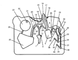
従来の試料液採取方法としては、図12に示す特許文献1の遠心移送式バイオセンサーがある。これは容器310の中に深さの異なる複数のキャビティが形成されている。試料液は入口313から毛細管現象により第1の毛細管キャビティ312内に採取され、次に遠心力を作用させることで、第1の毛細管キャビティ312内の試料液は、濾過材料315と第1の流路314を介して受入キャビティ317に移送され、受入キャビティ317で試薬と反応、および遠心分離させたのちに、芯318の毛細管力によって溶液成分のみを第2の毛細管キャビティ316に採取し、光学的に反応状態を読み取られる。
As a conventional sample solution collecting method, there is a centrifugal transfer biosensor of
また、図13に示す特許文献2の遠心移送式バイオセンサーがある。この図13では分配ユニット400の部分を示している。入口ポート409は、上部部分402を経て毛細管キャビティ404aにつながっている。毛細管キャビティ404aは導管部分405aを介して毛細管キャビティ404bにつながっている。以下同様に、導管部分405b,405c,405d,405eを介して毛細管キャビティ404b,404c,404d,404e,404fにつながっている。毛細管キャビティ404fは上部部分403を経て出口ポート410につながっている。上部部分402と導管部分405a〜405eおよび上部部分403には、通気孔406a〜406gが設けられている。入口ポート409から入った試料は、出口ポート410まで毛細管力で移送し、各毛細管キャビティ404a〜404fを試料液で満たした後、このバイオセンサーの回転によって発生する遠心力によって、それぞれの毛細管キャビティ404a〜404f内の試料液を各通気孔406a〜406gの位置で分配し、各バルブ408a〜408fと各連結微小導管407a〜407fを通って、次の処理室(図示省略)へ移送される。
しかしながら、このような従来の構成では、毛細管キャビティを充填するほどの試料液が与えられなかったり、点着の途中で試料液を注入口から離してしまったりした場合に、注入口付近の表面張力の影響による気泡の混入の問題がある。また、試料液の注入後における取り扱い時にデバイスの向きを変えてしまうことで、毛細管キャビティ内の試料液が動いてしまって気泡が混入したりする可能性がある。 However, in such a conventional configuration, when the sample liquid enough to fill the capillary cavity is not given, or when the sample liquid is separated from the inlet during the spotting, the surface tension near the inlet There is a problem of the mixing of bubbles due to the influence of. Further, by changing the orientation of the device during handling after injection of the sample solution, the sample solution in the capillary cavity may move and bubbles may be mixed in.
このような気泡の混入が発生すると、不足している試料液を後から追加して吸引させようとしても毛細管キャビティ内の気泡を外部に逃がすことができないため、気泡の部分に試料液を充填することができず、一定量の試料液を採取できないという課題を有している。 When such bubbles are mixed, the bubbles in the capillary cavity cannot be released to the outside even if an insufficient sample solution is added later and sucked, so the sample solution is filled in the bubbles. Cannot be collected, and a certain amount of sample solution cannot be collected.
本発明は、前記従来の課題を解決するもので、毛細管キャビティ内への気泡の混入を防ぐことができ、試料液の採取が毛細管キャビティを満たすまで何度でもできるマイクロチップを提供することを目的とする。 The present invention solves the above-described conventional problems, and an object thereof is to provide a microchip that can prevent air bubbles from being mixed into a capillary cavity and can collect a sample solution any number of times until the capillary cavity is filled. And
本発明の請求項1記載のマイクロチップは、マイクロチップ本体の一側から突出し試料液を採取する注入口と、前記注入口を介して毛細管力により一定量の試料液を採取することができる少なくとも1つの第1の毛細管キャビティと、前記第1の毛細管キャビティと連通するとともに軸心周りの回転によって発生する遠心力によって移送される前記第1の毛細管キャビティ内の試料液を受け取る第1の保持チャンバーとを備えるマイクロチップであって、前記注入口と前記第1の保持チャンバーとを連結する前記第1の毛細管キャビティの一側面に、毛細管力を発生せず、前記注入口のマイクロチップ本体から突出している部分で大気と連通するキャビティを設けたことを特徴とする。
The microchip according to
本発明の請求項2記載のマイクロチップは、請求項1において、前記第1の毛細管キャビティおよび前記キャビティの断面形状が矩形形状を有し、前記キャビティの厚み方向の断面寸法が前記第1の毛細管キャビティの断面寸法よりも大きく、前記キャビティが前記第1の毛細管キャビティの片側もしくは両側の側面に形成されていることを特徴とする。
Microchip according to
本発明の請求項3記載のマイクロチップは、請求項1において、前記第1の毛細管キャビティの断面形状の一部が円弧形状を有し、前記キャビティの断面形状が矩形形状を有し、前記キャビティの厚み方向の断面寸法が前記第1の毛細管キャビティの断面寸法よりも大きく、前記キャビティが前記第1の毛細管キャビティの片側もしくは両側の側面に形成されていることを特徴とする。
Microchip according to
本発明の請求項4記載のマイクロチップは、請求項2または請求項3において、前記キャビティの厚み方向の断面寸法が前記毛細管キャビティよりも50μm以上大きくなっていることを特徴とする。 A microchip according to a fourth aspect of the present invention is characterized in that, in the second or third aspect , a cross-sectional dimension in the thickness direction of the cavity is 50 μm or more larger than the capillary cavity.
本発明の請求項5記載のマイクロチップは、請求項1において、前記第1の毛細管キャビティおよび前記キャビティの断面形状の一部が円弧形状を有し、前記キャビティが前記第1の毛細管キャビティの片側もしくは両側の側面に形成されていることを特徴とする。
Microchip according to
本発明の請求項6記載のマイクロチップは、請求項1において、前記キャビティの壁面が疎水表面であることを特徴とする。
本発明の請求項7記載のマイクロチップは、請求項1において、前記第1の毛細管キャビティと連通し、前記第1の毛細管キャビティを経由して、毛細管力により一定量の試料液を採取することができる第2の毛細管キャビティと、前記第2の毛細管キャビティの外周端部と連通するとともに軸心周りの回転によって発生する遠心力によって移送される前記第2の毛細管キャビティ内の試料液を受け取る第2の保持チャンバーとを備え、前記第1の毛細管キャビティと前記第2の毛細管キャビティとの境界部が、前記第1の保持チャンバーおよび前記第2の保持チャンバーよりも内周側に位置しかつ内周方向に突出した湾曲形状を有し、前記境界部の外周側に壁面を有し、かつ、前記第2の毛細管キャビティの前記軸心周りの回転の内周側の一側面が、前記第1の毛細管キャビティの一側面に形成され毛細管力を発生せず大気と連通する前記キャビティに連通していることを特徴とする。
Microchip according to
A microchip according to a seventh aspect of the present invention is the microchip according to the first aspect, wherein the microchip communicates with the first capillary cavity and collects a predetermined amount of sample liquid by a capillary force via the first capillary cavity. A second capillary cavity capable of receiving the sample liquid in the second capillary cavity, which communicates with an outer peripheral end of the second capillary cavity and is transferred by centrifugal force generated by rotation around an axis. e Bei and 2 of the holding chamber, the boundary portion between the front Symbol first capillary cavity and said second capillary cavity is located on the inner peripheral side of the first holding chamber and second holding chamber and has a curved shape protruding toward the inner periphery, have a wall on the outer periphery side of the boundary portion and the inner circumferential side of the rotation of said axis around the second capillary cavity Side surface, characterized in that it communicates with the cavity which communicates with the atmosphere without generating an aspect formed in capillary force of the first capillary cavity.
本発明の請求項8記載のマイクロチップは、請求項7において、前記第2の毛細管キャビティから第N(Nは3以上の正の整数)の毛細管キャビティまで順次連通して形成されるN−2個の毛細管キャビティと、前記N−2個の毛細管キャビティの外周端部に連通するとともに軸心周りの回転によって発生する遠心力によって移送される前記N−2個の毛細管キャビティ内の試料液をそれぞれ受け取るN−2個の保持チャンバーを設け、前記第1の毛細管キャビティと前記第2の毛細管キャビティとの境界部が、前記第1の保持チャンバーおよび前記第2の保持チャンバーよりも内周側に位置しかつ内周方向に突出した湾曲形状を有し、前記第2の毛細管キャビティから順次連続して前記第Nの毛細管キャビティまで形成される前記N−2個の毛細管キャビティのN−2個の境界部が、前記第2の保持チャンバーから前記第Nの保持チャンバーまでのN−2個の保持チャンバーよりもそれぞれ内周側に位置しかつ内周方向に突出した湾曲形状を有し、前記第1の境界部から第N−1の境界部までのN−1個の境界部の外周側に壁面を有し、かつ、前記N−2個の毛細管キャビティの前記軸心周りの回転の内周側の一側面が、前記第1の毛細管キャビティの一側面に形成され毛細管力を発生せず大気と連通する前記キャビティに連通していることを特徴とする。 According to an eighth aspect of the present invention, in the microchip according to the seventh aspect, N-2 is formed by sequentially communicating from the second capillary cavity to the Nth (N is a positive integer of 3 or more) capillary cavity. Each of the sample liquids in the N-2 capillary cavities communicated with the peripheral ends of the N-2 capillary cavities and the centrifugal force generated by the rotation around the axis, respectively. the N-2 pieces of the holding chamber is provided, the boundary portion between the front Symbol first capillary cavity and said second capillary cavity, the inner peripheral side than the first holding chamber and the second holding chamber to receive The N-2 pieces which are located and have a curved shape protruding in the inner circumferential direction, and are formed sequentially from the second capillary cavity to the Nth capillary cavity. N-2 boundary portions of the capillary cavity are located on the inner peripheral side and protrude in the inner peripheral direction from the N-2 holding chambers from the second holding chamber to the Nth holding chamber. has a curved shape, the have a wall from a first boundary portion on the outer peripheral side of the N-1 boundary to the boundary portion of the first N-1, and said of said N-2 pieces of capillary cavity One side surface of the inner peripheral side of the rotation around the axis is formed on one side surface of the first capillary cavity and communicates with the cavity communicating with the atmosphere without generating a capillary force .
本発明のマイクロチップによれば、試料液を採取する毛細管キャビティに気泡が混入するのを防ぐことができるため、毛細管キャビティを満たすまで何度でも試料液を採取することができる。よって、試料液の採取不足による測定エラーをなくすことができるため、マイクロチップの測定精度を向上させることができる。 According to the microchip of the present invention, it is possible to prevent air bubbles from being mixed into the capillary cavity from which the sample liquid is collected. Therefore, the sample liquid can be collected any number of times until the capillary cavity is filled. Therefore, since measurement errors due to insufficient sampling of the sample liquid can be eliminated, the measurement accuracy of the microchip can be improved.
以下、本発明の各実施の形態を図1〜図11と図14に基づいて説明する。
(実施の形態1)
図1〜図8は本発明の実施の形態1を示す。
Embodiments of the present invention will be described below with reference to FIGS. 1 to 11 and FIG.
(Embodiment 1)
1 to 8
図1はマイクロチップ3を外観図で示したものである。図2はそのマイクロチップ3の構成を分解斜視図で示したものである。マイクロチップ3は、上部基板1と下部基板2との貼り合わせで構成されており、下部基板2の1つの面には、微細な凹凸形状をもつマイクロチャネル構造が形成されており、試料液の移送や、所定量の液量を保持するなど、それぞれの機能が働くようになっている。
FIG. 1 shows an external view of the
図3はマイクロチップ3がマイクロチップ保持部材101に装着される様子を示した外観斜視図であり、1つのマイクロチップ3がマイクロチップ保持部材101に装着されており、分析装置(図示せず)側の回転駆動手段により、マイクロチップ保持部材101及びマイクロチップ3が軸心11の所定の方向に回転される。
FIG. 3 is an external perspective view showing how the
また図4は、マイクロチップ3の注入口14の周辺部を示した拡大図であるが、図4に示すように注入口14は、マイクロチップ本体の一側面より軸心11方向に突出した形状にすることにより、指先などによる点着がしやすくなり、点着時に注入口14以外の位置に指などが接触して血液が付着するのを防ぐという効果がある。
4 is an enlarged view showing the peripheral portion of the
注入口14の周囲におけるマイクロチップ3の一側面には、軸心11側のみが開口し、さらに軸心11より外周方向に向けて窪む凹部12が形成されている。なお、本実施例では、凹部12は、凹部の軸心側における開口部の断面積が、凹部の外周側の開口部における断面積よりも同等以上の大きさになるように、ゆるやかに湾曲した構造になるように形成させることによって、遠心力が発生すると、注入口14の周囲に試料液が付着した試料液は、確実に凹部へ移送され、さらに凹部の一番低い位置へ移送されやすくなり、凹部外
へ飛散することなく、収集できるようになっている。
On one side surface of the
また、この開口されている凹部12の底面から軸心11方向に突出するように、注入口14を有する突起部を形成させることによって、注入口14の周囲に付着した試料液は、凹部内へ移送されるのであるが、移送されたその位置は、凹部内のほぼ底面なので、試料液は凹部内から溢れ出すことはなく安定して収集でき、また、1つの凹部で収集できるという効果も得られる。
Further, by forming a protrusion having the
図5は、本実施の形態1のマイクロチップ3が装着される分析装置1000の構成を示す模式図である。図5において、本マイクロチップ3は、分析装置1000の回転駆動手段であるモータ102の回転軸上に装着されているマイクロチップ保持部材101の上部へ装着され、モータ102を回転駆動させて、マイクロチップ3が装着されているマイクロチップ保持部材101を軸心周りに回転駆動させることができる。
FIG. 5 is a schematic diagram showing the configuration of the
本分析装置は、その用途に応じて、マイクロチップ3内のチャンバー及び流路の構成により、軸心周りの回転によって発生する遠心力を用いて、マイクロチップ内の液を移送したり、遠心分離したりする遠心分離機にもなりえる。なお、本発明ではマイクロチップ3を分析装置1000に装着しているが、そのマイクロチップの形状は、扇形状や、立方体形状やその他の形状のものでもよい。また、複数個のマイクロチップ3を分析装置1000に同時に装着してもかまわない。
Depending on the application, this analyzer uses the centrifugal force generated by the rotation around the axial center depending on the configuration of the chamber and flow path in the
また、本分析装置は、マイクロチップ保持部材101をモータ102によりC方向に回転駆動させながら、レーザー光源103よりレーザー光を、分析装置1000のマイクロチップ保持部材101に装着されているマイクロチップに向けて照射する。レーザー光源103は、トラバースモータ104で駆動される送りねじ105に螺合しており、サーボコントロール回路106が、レーザー光源103を任意の測定箇所に配置できるように、トラバースモータ104を駆動してレーザー光源103を、マイクロチップ保持部材101の径方向に移動できる。
In addition, the analyzer is configured to drive the laser light from the
マイクロチップ保持部材101の上部には、レーザー光源103から照射したレーザー光のうち、マイクロチップ保持部材101を透過した透過光の光量を検出するフォトディテクタ(PD)107、フォトディテクタ(PD)107の出力のゲインを調整する調整回路108、調整回路108の出力をデジタル変換するA/D変換器109、A/D変換器109でデジタル変換されたデータを処理する透過光量信号処理回路110、透過光量信号処理回路110で得られたデータを保存するメモリ113、これらを制御するマイクロコンピュータ(CPU)111、そして分析された結果を表示する表示部112を有している。
Above the
なお、本実施の形態では、光ディスクの光学スキャン技術は、特に用いていないが、別段、レーザー光源103のマイクロチップ3への照射に関しては、マイクロチップ3に位置情報を記録された領域を設けることによって、トラバースモータ104の駆動だけでなく、レーザー光源103の内部に設けられたトラッキングアクチェータ(図示せず)によって、レーザー光の光路をマイクロチップの面方向に必要に応じて併せて駆動して位置制御しながら正確にマイクロチップのトラックをトレースできるような構成にしてもよい。
In this embodiment, the optical scanning technique of the optical disc is not particularly used. However, regarding the irradiation of the
次に、本実施の形態1のマイクロチップ3のマイクロチャネル構成、および試料液の移送プロセスについて詳細に説明する。
図6は本実施の形態1のマイクロチップのマイクロチャネル構成を示す平面図である。図7は本実施の形態1の“マイクロチップの試料液注入過程”から“測定チャンバーの充填過程”を説明する図である。また、図8(a)〜図8(d)はそれぞれマイクロチップにおける毛細管キャビティおよびキャビティの断面形状例を示し、図8(a)は同実施の形態の毛細管キャビティ4およびキャビティ15,16の断面形状が矩形形状の場合の断面図、図8(b)は同実施の形態の毛細管キャビティ4およびキャビティ15の断面形状が円弧形状の場合の断面図、図8(c)は同実施の形態の毛細管キャビティ4の断面形状が円弧形状で、キャビティ15の断面形状が矩形形状の場合の断面図、図8(d)は同実施の形態の毛細管キャビティ4およびキャビティ15,16の断面形状が矩形形状で両者の厚みが同じ場合の断面図、図8(e)は同実施の形態の毛細管キャビティ4およびキャビティ15,16の断面形状が矩形形状で、キャビティ15,16の厚みが毛細管キャビティ4より大きい場合の断面図、図8(f)は同実施の形態の毛細管キャビティ4およびキャビティ15の断面形状が円弧形状で、キャビティ15の厚みが毛細管キャビティ4より大きい場合の断面図である。
Next, the microchannel configuration of the
FIG. 6 is a plan view showing a microchannel configuration of the microchip of the first embodiment. FIG. 7 is a diagram for explaining the “filling process of the measurement chamber” from the “microchip sample solution injection process” according to the first embodiment. 8A to 8D show examples of the cross-sectional shapes of the capillary cavity and the cavity in the microchip, respectively, and FIG. 8A shows the cross-sections of the
図6に示すように本実施の形態1のマイクロチップ3のマイクロチャネル構成は、試料液を採取する注入口14と、注入口14に注入された試料液を所定量だけ保持する毛細管キャビティ4と、毛細管キャビティ4内の空気を排出するキャビティ15,16と、分析試薬(図示せず)が保持されている保持チャンバー5と、試料液と分析試薬との混合物を測定する測定チャンバー7と、保持チャンバー5と測定チャンバー7に連通する流路6と、さらに測定チャンバー7と、大気開放孔9を連通させる流路8とで構成されている。ここで本発明では、毛細管キャビティ4、流路6、流路8の深さは50μm〜300μmで形成されているが、毛細管力で試料液が流れるのであれば、この寸法に限定されるものではない。また、保持チャンバー5、測定セル7、キャビティ15,16の深さは、0.3mm〜5mmで形成しているが、これは、サンプル溶液の量や、吸光度を測定する条件(光路長、測定波長、サンプル溶液の反応濃度、試薬の種類等)によって調整可能である。
As shown in FIG. 6, the microchannel configuration of the
本実施の形態1では、毛細管力で試料液を流すために、毛細管キャビティ4、流路6、流路8の壁面に親水処理を行っており、親水処理方法としては、プラズマ、コロナ、オゾン、フッ素等の活性ガスを用いた表面処理方法や、界面活性剤や親水性ポリマーによる表面処理が挙げられる。ここで親水性とは、水との接触角が90°未満のことをいい、より好ましくは接触角40°未満である。
In the first embodiment, in order to cause the sample liquid to flow with capillary force, hydrophilic treatment is performed on the wall surfaces of the
次に、図7を用いて試料液の移送プロセスの詳細を説明する。まず、この形態を持つマイクロチップ3に試料液を供給するためには、このマイクロチップ3をマイクロチップ保持部材101から取り外した状態で、マイクロチップ3の一側面より軸心11方向に突出した注入口14に試料液を点着させると、点着直後に、試料液は図7(a)に示すように毛細管現象により毛細管キャビティ4に所定量だけ注入される。
Next, the details of the sample liquid transfer process will be described with reference to FIG. First, in order to supply the sample solution to the
このとき、本発明では、毛細管キャビティ4の側面に毛細管キャビティ4内の空気を排出するキャビティ15,16を設けているため、試料液は毛細管キャビティ4の側面部が先行して流れる毛細流ではなく、毛細管キャビティ4の中央部が先行して流れる毛管流となって毛細管キャビティ4内を充填していく。そのため、注入口14に点着させる試料液が毛細管キャビティ4の充填途中で不足したり、試料液を充填途中で注入口14から離してしまったりした場合でも、再度、注入口から点着することで、試料液は毛細管キャビティ4の中央部が先行して流れるため、毛細管キャビティ内に保持されていた試料液の中央部と接触し、空気をキャビティ15,16のある側面方向に排出しながら充填されるため、気泡が発生せず、毛細管キャビティ4が所定量の試料液を保持できるまで、何度でも点着することが可能となる。
At this time, in the present invention, since the
毛細管キャビティ4とキャビティ15,16の構成としては、図8(a)に示すように下部基板に形成された矩形状の毛細管キャビティ4の片側もしくは両側の側面に、厚み方向の断面寸法が毛細管キャビティ4の断面寸法より大きくなるようなキャビティ15,16を設ける構成、図8(b)に示すように下部基板に形成された円弧形状の毛細管キャビティ4の片側もしくは両側の側面に、円弧形状のキャビティ15,16を設ける構成、図8(c)に示すように下部基板に形成された円弧形状の毛細管キャビティ4の片側もしくは両側の側面に、厚み方向の断面寸法が毛細管キャビティ4の断面寸法より大きくなるような矩形状のキャビティ15,16を設ける構成、図8(d)に示すように下部基板に形成された円弧形状の毛細管キャビティ4の片側もしくは両側の側面に、毛細管キャビティ4と厚み方向の断面寸法が同じ矩形状のキャビティ15,16を設け、キャビティ15,16の壁面が疎水表面もしくは疎水処理(疎水性の基準としては、水との接触角が90°以上が望ましいが、70°以上でもよい。)が施されている構成、図8(e)に示すように下部基板に形成された矩形状の毛細管キャビティ4の片側もしくは両側の側面に、厚み方向の断面寸法が毛細管キャビティ4の断面寸法より大きくなるように下部基板および上部基板の両方の基板にキャビティ15,16を設ける構成、図8(f)に示すように下部基板と上部基板の両方の基板に形成された円弧形状の毛細管キャビティ4の片側もしくは両側の側面に、下部基板および上部基板の両方の基板に円弧形状のキャビティ15,16を設ける構成、などが挙げられるが、本発明の毛細管キャビティとキャビティの構成はこれに限定されるものではない。
As the structure of the
図8(a),図8(c),図8(e)に示す構成では、キャビティ15,16の厚み方向の断面寸法を毛細管キャビティ4の断面寸法よりも50μm以上大きくすることで、試料液のキャビティ15,16への流入を抑制することができる。キャビティ15,16の厚み方向の断面寸法の上限値としては特に規定はないが、毛細管キャビティの厚み方向の断面寸法を保つために上部基板1に剛性をもたす必要があるため、上部基板1の表面からキャビティ15,16までの距離を0.5〜1mm程度とることが望ましい。また、毛細管キャビティ4に毛細管現象を働かすために親水処理を行う必要があるが、親水処理は毛細管キャビティ4の壁面のみにすることが望ましく、他のキャビティ15,16などの壁面に親水処理をしておくと、キャビティ内への試料液の流入が起こってしまう。
8 (a), 8 (c), and 8 (e), the sample liquid is obtained by making the cross-sectional dimension of the
毛細管キャビティ4に試料液が充填された後、マイクロチップ3を分析装置1000に取り付け、分析装置1000の回転駆動手段によってマイクロチップ3を回転させることで、図7(b)に示すように毛細管キャビティ4内の試料液は遠心力によって分析試薬があらかじめ担持されている保持チャンバー5内に移送される。
After the
保持チャンバー5内に流入した試料液は、分析装置1000の回転の加速度による揺動や回転停止中の液の拡散によって、保持チャンバー5内に担持されている分析試薬と混合されるが、保持チャンバー5自体を直接振動させるような外的な力を作用させて混合することも可能である。
The sample liquid that has flowed into the holding
次に試薬と試料液との混合が所定のレベルに到達すると、保持チャンバー5内の試料液は、図7(c)に示すように毛細管力で流路6内を通じて測定チャンバー7の入口まで移送される。
Next, when the mixing of the reagent and the sample liquid reaches a predetermined level, the sample liquid in the holding
次に分析装置の回転で、図7(d)に示すように流路6内の試料液は測定チャンバー7内に移送され、分析装置1000により、試料液と分析試薬との反応状態を吸光度測定などによって測定することにより、その成分の濃度を測定することができる。
Next, as shown in FIG. 7D, the sample liquid in the
(実施の形態2)
図9〜図11は本発明の実施の形態2を示す。
図9は本実施の形態2のマイクロチップのマイクロチャネル構成を示す平面図である。図10は本実施の形態2の“マイクロチップの試料液注入過程”から“測定チャンバーの充填過程”を説明する図である。また、図11は本発明の実施の形態2の“マイクロチップの試料液分配過程”を説明する拡大図である。
(Embodiment 2)
9 to 11 show a second embodiment of the present invention.
FIG. 9 is a plan view showing the microchannel configuration of the microchip of the second embodiment. FIG. 10 is a diagram for explaining the “filling process of the measurement chamber” from the “microchip sample solution injection process” according to the second embodiment. FIG. 11 is an enlarged view for explaining the “microchip sample solution distribution process” according to the second embodiment of the present invention.
なお、本実施の形態2によるマイクロチップの主な構成、および該マイクロチップが装着される分析装置1000の構成については、実施の形態1で説明した内容と同じであるため、ここでは説明を省略する。
Since the main configuration of the microchip according to the second embodiment and the configuration of the
図9に示すように本実施の形態2のマイクロチップ3のマイクロチャネル構成は、試料液を採取する注入口14と、注入口14に注入された試料液を所定量だけ保持する第1の毛細管キャビティ17と、第1の毛細管キャビティ17を経由して試料液を所定量だけ保持する第2の毛細管キャビティ19と、第2の毛細管キャビティ19を経由して試料液を所定量だけ保持する第3の毛細管キャビティ21と、毛細管キャビティ17,19内の空気を排出するキャビティ15,16と、第1の毛細管キャビティ17内の試料液を受け取り、固体成分の入った試料液を溶液成分と固体成分とに分離する収容室また第1の保持チャンバーとしての保持チャンバー5と、第2の毛細管キャビティ19内の試料液を受け取り試料液の溶液成分と固体成分の比率を測定する第2の保持チャンバーとしての測定チャンバー7と、第3の毛細管キャビティ21内の試料液と希釈液収容チャンバー23内に注入された希釈液とを受け取り、内部で混合して試料液内の成分測定を行う第3の保持チャンバーとしての測定チャンバー25と、保持チャンバー5内で分離された試料液の溶液成分を流路26を経由して所定量だけ保持する第4の毛細管キャビティ28と、第4の毛細管キャビティ28を経由して、溶液成分を所定量だけ保持する第5の毛細管キャビティ30と、第4の毛細管キャビティ28内の試料液を受け取り、試料液と分析試薬との混合物を測定する第4の保持チャンバーとしての測定チャンバー34と、第5の毛細管キャビティ30内の試料液を受け取り、試料液と分析試薬との混合物を測定する第5の保持チャンバーとしての測定チャンバー38と、第4の毛細管キャビティ28の終端に連通したバルブ31と測定チャンバー34に連通する流路33と、さらに測定チャンバー34と、大気開放孔36を連通させる流路35と、第5の毛細管キャビティ30の終端に連通したバルブ32と測定チャンバー38に連通する流路37と、さらに測定チャンバー38と、大気開放孔40を連通させる流路39とで構成されている。
As shown in FIG. 9, the microchannel configuration of the
ここで本発明では、第1の毛細管キャビティ14、第2の毛細管キャビティ19、第3の毛細管キャビティ21、流路24、流路26、第4の毛細管キャビティ28、第5の毛細管キャビティ30、流路33、流路35、流路37、流路39の深さは50μm〜300μmで形成されているが、毛細管力で試料液が流れるのであれば、この寸法に限定されるものではない。また、保持チャンバー5、測定セル7、希釈液収容チャンバー23、キャビティ15,16、測定チャンバー25、バルブ31,32、測定チャンバー36、測定チャンバー38の深さは、0.3mm〜5mmで形成しているが、これは、サンプル溶液の量や、吸光度を測定する条件(光路長、測定波長、サンプル溶液の反応濃度、試薬の種類等)によって調整可能である。
Here, in the present invention, the first
本実施の形態2では、毛細管力で試料液を流すために、第1の毛細管キャビティ14、第2の毛細管キャビティ19、第3の毛細管キャビティ21、流路24、流路26、第4の毛細管キャビティ28、第5の毛細管キャビティ30、流路33、流路35、流路37、流路39の壁面に親水処理を行っており、親水処理方法としては、プラズマ、コロナ、オゾン、フッ素等の活性ガスを用いた表面処理方法や、界面活性剤や親水性ポリマーによる表面処理が挙げられる。ここで親水性とは、水との接触角が90°未満のことをいい、より好ましくは接触角40°未満である。
In the second embodiment, the first
次に図10を用いて試料液の移送プロセスの詳細を説明する。
まず、この形態を持つマイクロチップ3に試料液を供給するためには、このマイクロチップ3をマイクロチップ保持部材101から取り外した状態で、マイクロチップ3の一側面より軸心11の方向に突出した注入口14に試料液を点着させると、点着直後に、試料液は図10(a)に示すように毛細管現象により第1の毛細管キャビティ17に所定量だけ注入され、次に第1の毛細管キャビティ17を経由して、第2の毛細管キャビティ19に所定量だけ注入され、さらに、第2の毛細管キャビティ19を経由して、第3の毛細管キャビティ21に所定量だけ注入される。
Next, details of the sample liquid transfer process will be described with reference to FIG.
First, in order to supply the sample solution to the
このとき、本発明では、第1の毛細管キャビティ17の両側面、第2の毛細管キャビティ19、および第3の毛細管キャビティ21の内周方向の側面に、それぞれの毛細管キャビティ内の空気を排出するキャビティ15,16を設けているため、試料液は毛細管キャビティの側面部が先行して流れる毛細流ではなく、毛細管キャビティの中央部が先行して流れる毛管流となってそれぞれの毛細管キャビティ内を充填していく。
At this time, in the present invention, the cavities for discharging the air in the capillary cavities on both side surfaces of the first
そのため、注入口14に点着させる試料液がそれぞれの毛細管キャビティの充填途中で不足したり、試料液を充填途中で注入口14から離してしまったりした場合でも、再度、注入口から点着することで、試料液は毛細管キャビティの中央部が先行して流れるため、毛細管キャビティ内に保持されていた試料液の中央部と接触し、空気をキャビティ15,16のある側面方向に排出しながら充填されるため、気泡が発生せず、それぞれの毛細管キャビティが所定量の試料液を保持できるまで、何度でも点着することが可能となる。
Therefore, even when the sample liquid to be spotted on the
第1の毛細管キャビティ17、第2の毛細管キャビティ19、第3の毛細管キャビティ21とキャビティ15,16の構成としては、実施の形態1と同様の構成であるため、説明を省略する。
The configurations of the first
第1の毛細管キャビティ17、第2の毛細管キャビティ19、および第3の毛細管キャビティ21に試料液が充填された後、注入口22より所定量の希釈液を希釈液収容チャンバー23へ注入し、その後にこのマイクロチップ3を分析装置1000に取り付け、分析装置1000の回転駆動手段によってマイクロチップ3を回転させることで、図10(b)に示すように遠心力によって、注入口14から境界部としての第1の分配位置18の間に保持されていた第1の毛細管キャビティ17内の試料液は、第1の分配位置18で破断し、保持チャンバー5へ移送され、第1の分配位置18から境界部としての第2の分配位置20の間に保持されていた第2の毛細管キャビティ19内の試料液は、第1の分配位置18、および第2の分配位置20で破断し、測定チャンバー7へ移送され、さらに、第2の分配位置20から測定チャンバー25の間に保持されていた第3の毛細管キャビティ21内の試料液は、第2の分配位置20で破断し、測定チャンバー25へ移送される。また、希釈液収容チャンバー23内の希釈液は、遠心力によって流路24を経由して測定チャンバー25に移送される。
After the first
ここで本発明では、第1の毛細管キャビティ17と、第2の毛細管キャビティ19との境界部である第1の分配位置18と、第2の毛細管キャビティ19と、第3の毛細管キャビティ21との境界部である第2の分配位置20が、保持チャンバー5、測定チャンバー7、および測定チャンバー25よりも内周側の位置で、内周方向に突出した湾曲形状を有しており、さらに、第1の毛細管キャビティ17、第2の毛細管キャビティ19、および第3の毛細管キャビティ21の側面にキャビティ15,16を設けているため、遠心力によってそれぞれの毛細管キャビティ内の試料液を外周方向へ移送する際に、図11に示すように第1の分配位置18、および第2の分配位置20の最内周位置より試料液に遠心力が働いて、試料液を破断させても毛細管キャビティ間の圧力差やサイフォン効果が発生しにくくなっているため、それぞれの試料液を精度よく分配させることができる。図14(a),図14(b),図14(c)はそれぞれ図9に示したA−A′線,C−C′線,D−D′線に沿った断面図を示す。第1の毛細管キャビティ17と第2の毛細管キャビティ19との境界部としての第1の分配位置18は、保持チャンバー5および第2の保持チャンバーとしての測定チャンバー7よりも内周側に位置しかつ内周方向に突出した湾曲形状を有し、外周側に壁面B1を有している。
Here, in the present invention, the
また、保持チャンバーとしての測定チャンバー7から順次連続して形成された第3の毛細管キャビティ21の境界部としての第2の分配位置20は、保持チャンバー5および第2の保持チャンバーとしての測定チャンバー7よりも内周側に位置しかつ内周方向に突出した湾曲形状を有し、外周側に壁面B2を有している。
In addition, the
また、第4の毛細管キャビティ28と第5の毛細管キャビティ30との境界部である第3の分配位置27は、保持チャンバー5および前記第2の保持チャンバーよりも内周側の位置で、内周方向に突出した湾曲形状を有し、第3の分配位置27の外周側に壁面B3を有している。
The
従来、毛細管キャビティ内に充填された試料液を遠心力によって分配移送する場合には、図13に示すような毛細管キャビティの分配位置のみに通気孔を設けた構成では、遠心力をかけた際に、毛細管キャビティ内に液量や毛細管キャビティの断面寸法の違いによって圧力差が生じたり、サイフォン効果が生じたりする。そのため、分配位置で試料液が破断されるまでの間、どちらかの毛細管キャビティに試料液が引き込まれて所定量より多く流入するため、精度のよい分配移送ができないという課題を有していた。 Conventionally, when the sample liquid filled in the capillary cavity is distributed and transferred by centrifugal force, in the configuration in which vent holes are provided only at the distribution position of the capillary cavity as shown in FIG. 13, when the centrifugal force is applied. Depending on the amount of liquid in the capillary cavity and the difference in cross-sectional dimensions of the capillary cavity, a pressure difference or siphon effect may occur. Therefore, until the sample liquid is broken at the distribution position, the sample liquid is drawn into one of the capillary cavities and flows more than a predetermined amount, so that there is a problem that accurate distribution and transfer cannot be performed.
しかしながら本実施の形態の構成によれば、毛細管キャビティ内の試料液を分配する際に、毛細管キャビティ間の圧力差やサイフォン効果を発生させずに分配できるので、試料液の分配精度を向上させることができる。 However, according to the configuration of the present embodiment, when the sample liquid in the capillary cavity is distributed, it can be distributed without generating a pressure difference between the capillary cavities and a siphon effect, so that the distribution accuracy of the sample liquid is improved. Can do.
また、試料液の分配数は、測定項目の数によって調整することが可能であり、N個の分配が必要な場合は、毛細管キャビティをN個設けて、それぞれの毛細管キャビティに混合
チャンバーや、測定チャンバーなどの保持チャンバーを連通させることができるため、本実施の形態2に記載の内容に限定されるものではない。
In addition, the number of sample liquid distribution can be adjusted according to the number of measurement items. When N distributions are required, N capillary cavities are provided, and each capillary cavity has a mixing chamber or measurement. Since a holding chamber such as a chamber can be communicated, it is not limited to the contents described in the second embodiment.
さらに本発明では、注入口14に連通する第1の毛細管キャビティ17の1箇所から一方向に向かって連続する毛細管キャビティに試料液を充填させているが、第1の毛細管キャビティ17の2箇所以上から左右の両方向に向かって毛細管キャビティを連続させて試料液を充填させてもよい。
Furthermore, in the present invention, the sample solution is filled into the capillary cavity continuous in one direction from one location of the first
保持チャンバー5、および測定チャンバー7内に流入した試料液は、遠心力によって溶液成分と固体成分に分離される。また、測定チャンバー25内に流入した試料液と希釈液は、分析装置1000の回転の加速度による揺動や回転停止中の液の拡散によって混合されるが、測定チャンバー25自体を直接に振動させるような外的な力を作用させて混合することも可能である。
The sample liquid that has flowed into the holding
次に保持チャンバー5内の試料液の分離が所定のレベルに達成すると、マイクロチップ3の回転を停止させ、図10(c)に示すように保持チャンバー5内の溶液成分のみを毛細管力で流路26を経由して、第4の毛細管キャビティ28に所定量だけ充填され、さらに第4の毛細管キャビティ28を経由して、第5の毛細管キャビティ30に所定の量だけ充填される。
Next, when the separation of the sample solution in the holding
第4の毛細管キャビティ28の終端には、厚み方向の断面寸法が第4の毛細管キャビティ28よりも大きなバルブ31が設けられており、第4の毛細管キャビティ28内に流入された試料液の毛細管流はバルブ31で停止する。同様に、第5の毛細管キャビティ30の終端には、厚み方向の断面寸法が第5の毛細管キャビティ30よりも大きなバルブ32が設けられており、第5の毛細管キャビティ30内に流入された試料液の毛細管流はバルブ32で停止する。
At the end of the fourth
このとき、本発明では、第4の毛細管キャビティ28、および第5の毛細管キャビティ30の内周方向の側面に、それぞれの毛細管キャビティ内の空気を排出するキャビティ16を設けているため、試料液は毛細管キャビティの外周側の側面部が先行して流れる毛細流となってそれぞれの毛細管キャビティ内を充填していく。そのため、保持チャンバー5から試料液がそれぞれの毛細管キャビティに充填されていく途中で、空気をキャビティ16のある内周側の側面方向に排出しながら充填されるため、毛細管キャビティ内に気泡が発生せず、それぞれの毛細管キャビティ内を試料液で満たすことが可能となる。
At this time, in the present invention, since the
第4の毛細管キャビティ28、第5の毛細管キャビティ30、流路26とキャビティ16の構成としては、実施の形態1と同様の構成であるため、説明を省略する。
第4の毛細管キャビティ28、および第5の毛細管キャビティ30が充填された後、分析装置1000の回転駆動手段によって、マイクロチップ3を回転させることで、図10(d)に示すように遠心力によって、第3の分配位置27から境界部としての第4の分配位置29の間に保持されていた第4の毛細管キャビティ28内の試料液は、第3の分配位置27、および第4の分配位置29で破断し、バルブ32と流路33を経由して測定チャンバー34へ移送され、さらに、第4の分配位置29からバルブ32の間に保持されていた第5の毛細管キャビティ30内の試料液は、第4の分配位置29で破断し、バルブ32と流路37を経由して、測定チャンバー38へ移送される。
The configurations of the fourth
After the fourth
ここで本発明では、流路26と、第4の毛細管キャビティ28との境界部である第3の分配位置27と、第4の毛細管キャビティ28と、第5の毛細管キャビティ30との境界部である第4の分配位置29が、測定チャンバー34、および測定チャンバー38よりも内周側の位置で、内周方向に突出した湾曲形状を有しており、さらに、第4の毛細管キャビティ28、および第5の毛細管キャビティ30の側面にキャビティ16を設けているため、遠心力によってそれぞれの毛細管キャビティ内の試料液を外周方向へ移送する際に、第3の分配位置27、および第4の分配位置29の最内周位置より試料液に遠心力が働いて、試料液を破断させても、毛細管キャビティ間の圧力差やサイフォン効果が発生しにくくなっているため、それぞれの試料液を精度よく分配できる。
Here, in the present invention, at the boundary between the
また、試料液の分配数は、測定項目の数によって調整することが可能であり、N個の分配が必要な場合は、毛細管キャビティをN個設けて、それぞれの毛細管キャビティに混合チャンバーや、測定チャンバーなどの保持チャンバーを連通させることができるため、本実施の形態2に記載の内容に限定されない。
In addition, the number of sample liquid distribution can be adjusted according to the number of measurement items. When N distributions are required, N capillary cavities are provided, and each capillary cavity has a mixing chamber or measurement. Since a holding chamber such as a chamber can be communicated, the contents are not limited to those described in
さらに、本発明では、保持チャンバー5の1箇所から一方向に向かって連続する毛細管キャビティに試料液を充填させているが、保持チャンバー5の2箇所以上から左右の両方向に向かって毛細管キャビティを連続させ、試料液を充填させてもよい。
Further, in the present invention, the sample solution is filled into the capillary cavity that continues from one place of the holding
測定チャンバー34、および測定チャンバー38に移送された試料液は、分析装置に取り付けられている測定器(図示せず)により、試料液と分析試薬との反応状態を吸光度測定などによって測定することにより、その成分の濃度を測定できる。
The sample liquid transferred to the
試料液が血液の場合であれば、ヘマトクリット値(血漿と血球の比率)を測定チャンバー7で測定したり、赤血球中に含まれるヘモグロビンの濃度を測定チャンバー25で測定したり、血漿中に含まれるグルコースや、コレステロールなどの脂質成分を保持チャンバー5で分離された血漿を用いて測定できる。
If the sample liquid is blood, the hematocrit value (ratio of plasma to blood cells) is measured in the
本発明にかかるマイクロチップは、試料液を採取する毛細管キャビティに気泡が混入するのを防ぎ、毛細管キャビティを満たすまで何度でも試料液を採取することができるという効果や、試料液の分配精度を向上させることができるという効果を有し、電気化学式センサーや光学式センサーで生物学的流体の成分測定に使用するマイクロチップにおける試料液の採取方法、分配移送方法等として有用である。 The microchip according to the present invention prevents the bubbles from being mixed into the capillary cavity for collecting the sample liquid, and has the effect that the sample liquid can be collected any number of times until the capillary cavity is filled, and the distribution accuracy of the sample liquid is improved. It has the effect that it can be improved, and is useful as a sample liquid collection method, a distribution transfer method, and the like in a microchip used for measuring components of biological fluids with an electrochemical sensor or an optical sensor.
1 上部基板
2 下部基板
3 マイクロチップ
4 毛細管キャビティ
5 保持チャンバー
6 流路
7 測定セル
8 流路
9 大気開放孔
11 軸心
12 凹部
14 注入口
15 キャビティ
16 キャビティ
17 第1の毛細管キャビティ
18 第1の分配位置
19 第2の毛細管キャビティ
20 第2の分配位置
21 第3の毛細管キャビティ
23 試料液と希釈液収容チャンバー
25 測定チャンバー
26 流路
27 第3の分配位置
28 第4の毛細管キャビティ
29 第4の分配位置
30 第5の毛細管キャビティ
31 バルブ
32 バルブ
33 流路
34 測定チャンバー
35 流路
36 大気開放孔
37 流路
38 測定チャンバー
39 流路
40 大気開放孔40
101 マイクロチップ保持部材
102 モータ
103 レーザー光源
104 トラバースモータ
105 送りねじ
106 サーボコントロール回路
107 フォトディテクタ(PD)
108 調整回路
109 A/D変換器
110 透過光量信号処理回路
111 マイクロコンピュータ(CPU)
112 表示部
113 メモリ
1000 分析装置
B1 壁面
DESCRIPTION OF
101
108 adjustment circuit 109 A /
112
Claims (8)
前記注入口と前記第1の保持チャンバーとを連結する前記第1の毛細管キャビティの一側面に、毛細管力を発生せず、前記注入口のマイクロチップ本体から突出している部分で大気と連通するキャビティを設けた
マイクロチップ。 An inlet that protrudes from one side of the microchip body and collects a sample solution; at least one first capillary cavity that can collect a certain amount of sample solution by capillary force through the inlet; and the first A first holding chamber that communicates with the capillary cavity and receives the sample liquid in the first capillary cavity that is transferred by centrifugal force generated by rotation around the axis,
A cavity that does not generate a capillary force on one side surface of the first capillary cavity that connects the inlet and the first holding chamber and communicates with the atmosphere at a portion protruding from the microchip body of the inlet. Microchip provided with.
請求項1に記載のマイクロチップ。 The cross-sectional shape of the first capillary cavity and the cavity has a rectangular shape, the cross-sectional dimension in the thickness direction of the cavity is larger than the cross-sectional dimension of the first capillary cavity, and the cavity is the first capillary cavity. The microchip according to claim 1, wherein the microchip is formed on one or both side surfaces.
前記キャビティの断面形状が矩形形状を有し、
前記キャビティの厚み方向の断面寸法が前記第1の毛細管キャビティの断面寸法よりも大きく、前記キャビティが前記第1の毛細管キャビティの片側もしくは両側の側面に形成されていることを特徴とする
請求項1に記載のマイクロチップ。 A portion of the cross-sectional shape of the first capillary cavity has an arc shape,
The cross-sectional shape of the cavity has a rectangular shape,
The cross-sectional dimension of the cavity in the thickness direction is larger than the cross-sectional dimension of the first capillary cavity, and the cavity is formed on one or both side surfaces of the first capillary cavity. A microchip according to claim 1.
請求項2または請求項3に記載のマイクロチップ。 4. The microchip according to claim 2, wherein a cross-sectional dimension of the cavity in a thickness direction is 50 μm or more larger than that of the first capillary cavity. 5.
前記キャビティが前記第1の毛細管キャビティの片側もしくは両側の側面に形成されていることを特徴とする
請求項1に記載のマイクロチップ。 A portion of the cross-sectional shape of the first capillary cavity and the cavity has an arc shape;
2. The microchip according to claim 1, wherein the cavity is formed on one or both side surfaces of the first capillary cavity.
請求項1に記載のマイクロチップ。 The microchip according to claim 1, wherein a wall surface of the cavity is a hydrophobic surface.
前記第1の毛細管キャビティと前記第2の毛細管キャビティとの境界部が、前記第1の保持チャンバーおよび前記第2の保持チャンバーよりも内周側に位置しかつ内周方向に突出した湾曲形状を有し、前記境界部の外周側に壁面を有し、かつ、前記第2の毛細管キャビティの前記軸心周りの回転の内周側の一側面が、前記第1の毛細管キャビティの一側面に形成され毛細管力を発生せず大気と連通する前記キャビティに連通している
請求項1記載のマイクロチップ。 A second capillary cavity communicating with the first capillary cavity and capable of collecting a certain amount of sample liquid by capillary force via the first capillary cavity; and an outer periphery of the second capillary cavity A second holding chamber that communicates with the end and receives the sample liquid in the second capillary cavity that is transferred by centrifugal force generated by rotation around the axis;
A boundary portion between the first capillary cavity and the second capillary cavity is located on the inner peripheral side of the first holding chamber and the second holding chamber and has a curved shape protruding in the inner peripheral direction. And having a wall surface on the outer peripheral side of the boundary portion, and forming one side surface on the inner peripheral side of rotation around the axis of the second capillary cavity on one side surface of the first capillary cavity The microchip according to claim 1, wherein the microchip communicates with the cavity communicating with the atmosphere without generating capillary force.
前記N−2個の毛細管キャビティの外周端部に連通するとともに軸心周りの回転によって発生する遠心力によって移送される前記N−2個の毛細管キャビティ内の試料液をそれぞれ受け取るN−2個の保持チャンバーを設け、
前記第1の毛細管キャビティと前記第2の毛細管キャビティとの境界部が、前記第1の保持チャンバーおよび前記第2の保持チャンバーよりも内周側に位置しかつ内周方向に突出した湾曲形状を有し、
前記第2の毛細管キャビティから順次連続して前記第Nの毛細管キャビティまで形成される前記N−2個の毛細管キャビティのN−2個の境界部が、前記第2の保持チャンバーから前記第Nの保持チャンバーまでのN−2個の保持チャンバーよりもそれぞれ内周側に位置しかつ内周方向に突出した湾曲形状を有し、前記第1の境界部から第N−1の境界部までのN−1個の境界部の外周側に壁面を有し、かつ、前記N−2個の毛細管キャビティの前記軸心周りの回転の内周側の一側面が、前記第1の毛細管キャビティの一側面に形成され毛細管力を発生せず大気と連通する前記キャビティに連通している
請求項7記載のマイクロチップ。 N-2 capillary cavities formed in sequential communication from the second capillary cavity to the Nth (N is a positive integer greater than or equal to 3) capillary cavity;
The N-2 capillary cavities communicate with the outer peripheral ends of the N-2 capillary cavities and receive the sample liquid in the N-2 capillary cavities respectively transferred by centrifugal force generated by rotation around the axis. A holding chamber,
A boundary portion between the first capillary cavity and the second capillary cavity is located on the inner peripheral side of the first holding chamber and the second holding chamber and has a curved shape protruding in the inner peripheral direction. Have
N-2 boundaries of the N-2 capillary cavities formed sequentially from the second capillary cavity to the Nth capillary cavity are connected to the Nth capillary cavity from the second holding chamber. N-2 from the first boundary portion to the (N-1) th boundary portion, each having a curved shape that is located on the inner peripheral side and protrudes in the inner peripheral direction from the N-2 holding chambers up to the holding chamber. -1 has a wall surface on the outer peripheral side of one boundary portion, and one side surface on the inner peripheral side of the rotation around the axis of the N-2 capillary cavities is one side surface of the first capillary cavity 8. The microchip according to claim 7, wherein the microchip communicates with the cavity that is formed in the structure and does not generate capillary force and communicates with the atmosphere.
Priority Applications (1)
| Application Number | Priority Date | Filing Date | Title |
|---|---|---|---|
| JP2008542054A JP5247460B2 (en) | 2006-10-31 | 2007-10-23 | Microchip |
Applications Claiming Priority (4)
| Application Number | Priority Date | Filing Date | Title |
|---|---|---|---|
| JP2006295159 | 2006-10-31 | ||
| JP2006295159 | 2006-10-31 | ||
| JP2008542054A JP5247460B2 (en) | 2006-10-31 | 2007-10-23 | Microchip |
| PCT/JP2007/070603 WO2008053743A1 (en) | 2006-10-31 | 2007-10-23 | Microchip and analyzer using the same |
Publications (2)
| Publication Number | Publication Date |
|---|---|
| JPWO2008053743A1 JPWO2008053743A1 (en) | 2010-02-25 |
| JP5247460B2 true JP5247460B2 (en) | 2013-07-24 |
Family
ID=39344086
Family Applications (1)
| Application Number | Title | Priority Date | Filing Date |
|---|---|---|---|
| JP2008542054A Active JP5247460B2 (en) | 2006-10-31 | 2007-10-23 | Microchip |
Country Status (4)
| Country | Link |
|---|---|
| US (1) | US8512638B2 (en) |
| EP (1) | EP2096444B1 (en) |
| JP (1) | JP5247460B2 (en) |
| WO (1) | WO2008053743A1 (en) |
Families Citing this family (34)
| Publication number | Priority date | Publication date | Assignee | Title |
|---|---|---|---|---|
| CN102077096A (en) * | 2008-07-10 | 2011-05-25 | 三光纯药株式会社 | Disc for clinical examination, disc pack and clinical examination device |
| CN103487594B (en) | 2008-07-17 | 2015-02-18 | 松下健康医疗器械株式会社 | Analyzing device, and analyzing method using the analyzing device |
| JP5487466B2 (en) * | 2008-08-28 | 2014-05-07 | パナソニックヘルスケア株式会社 | Analytical device |
| US8546129B2 (en) * | 2009-03-31 | 2013-10-01 | Toppan Printing Co., Ltd. | Sample analysis chip, sample analyzer using sample analysis chip, sample analysis method, and method of producing sample analysis chip |
| JP2012013552A (en) * | 2010-06-30 | 2012-01-19 | Brother Ind Ltd | Inspection object acceptor |
| JP5728217B2 (en) * | 2010-12-14 | 2015-06-03 | ローム株式会社 | Microchip and inspection or analysis method using the same |
| WO2013112877A1 (en) | 2012-01-25 | 2013-08-01 | Tasso, Inc. | Handheld device for drawing, collecting, and analyzing bodily fluid |
| AU2013293078B2 (en) * | 2012-07-23 | 2017-09-07 | Tasso, Inc. | Methods, systems, and devices relating to open microfluidic channels |
| EP2777499B1 (en) * | 2013-03-15 | 2015-09-16 | Ortho-Clinical Diagnostics Inc | Rotatable fluid sample collection device |
| EP2778679B1 (en) * | 2013-03-15 | 2017-09-27 | Ortho-Clinical Diagnostics, Inc. | Rotable disk-shaped fluid sample collection device |
| CN106489072B (en) * | 2014-06-06 | 2019-05-14 | 豪夫迈·罗氏有限公司 | The rotating cylinder for being used to analyze biological sample with measuring room |
| EP2952257A1 (en) * | 2014-06-06 | 2015-12-09 | Roche Diagnostics GmbH | Rotatable cartridge for processing and analyzing a biological sample |
| CN106662596A (en) | 2014-06-30 | 2017-05-10 | 松下健康医疗控股株式会社 | Substrate for sample analysis, and sample analysis apparatus |
| JP6588910B2 (en) | 2014-06-30 | 2019-10-09 | Phcホールディングス株式会社 | Sample analysis substrate, sample analysis apparatus, sample analysis system, and program for sample analysis system |
| WO2016002727A1 (en) | 2014-06-30 | 2016-01-07 | パナソニックヘルスケアホールディングス株式会社 | Substrate for sample analysis, sample analysis device, sample analysis system, and program for sample analysis system |
| EP3163307B1 (en) | 2014-06-30 | 2021-03-03 | PHC Holdings Corporation | Substrate for sample analysis, sample analysis device, sample analysis system, and method for removing liquid from liquid that contains magnetic particles |
| CN113440134A (en) | 2014-08-01 | 2021-09-28 | 塔索公司 | Devices, systems, and methods for gravity-enhanced microfluidic collection, handling, and delivery of liquids |
| CN107209193B (en) | 2014-12-12 | 2019-08-02 | 普和希控股公司 | Sample analysis substrate, sample analyzer, sample analysis system and sample analysis system program |
| CN107530035A (en) * | 2015-01-14 | 2018-01-02 | 弗朗克·托马斯·哈特利 | For extracting the device and method thereof of body fluid |
| TWI562829B (en) * | 2015-06-17 | 2016-12-21 | Delta Electronics Inc | Centrifugal channel device and centrifugal channel main body |
| EP3760106B1 (en) | 2015-12-21 | 2024-04-10 | Tasso, Inc. | Devices for actuation and retraction in fluid collection |
| JP6823824B2 (en) * | 2016-09-01 | 2021-02-03 | 山梨県 | Microfluidic device |
| EP3511700B1 (en) * | 2016-09-06 | 2023-10-04 | Keio University | Method for measuring a uv or infrared protection effect of an aqueous composition and device for preparing a measurement sample |
| GB2555403B (en) | 2016-10-24 | 2021-03-24 | Entia Ltd | A Cuvette |
| WO2018077983A1 (en) | 2016-10-26 | 2018-05-03 | Radisens Diagnostics Limited | A point-of-care diagnostic assay cartridge |
| US11420203B2 (en) * | 2016-10-26 | 2022-08-23 | Radisens Diagnostics Limited | Point-of-care diagnostic assay cartridge |
| US11946943B2 (en) | 2018-02-09 | 2024-04-02 | Phc Holdings Corporation | Substrate for sample analysis, sample analysis device, sample analysis system, and method for controlling sample analysis device |
| GB201806931D0 (en) * | 2018-04-27 | 2018-06-13 | Radisens Diagnostics Ltd | An improved point-of-care diagnostic assay cartridge |
| EP4278983A3 (en) | 2018-09-14 | 2023-12-20 | Tasso, Inc. | Bodily fluid collection device |
| GB201915499D0 (en) | 2019-10-25 | 2019-12-11 | Radisens Diagnostics Ltd | A point-of-care test cartridge |
| GB2607337A (en) | 2021-06-04 | 2022-12-07 | Entia Ltd | A cuvette |
| GB2616667A (en) | 2022-03-18 | 2023-09-20 | Entia Ltd | A composition for coating a cuvette and a method of making a composition for coating a cuvette |
| GB2616840A (en) | 2022-03-18 | 2023-09-27 | Entia Ltd | A cuvette for analysing biological samples |
| GB2616668A (en) | 2022-03-18 | 2023-09-20 | Entia Ltd | A method of obtaining an image of a biological sample in a cuvette |
Citations (10)
| Publication number | Priority date | Publication date | Assignee | Title |
|---|---|---|---|---|
| JPH04504758A (en) * | 1989-04-26 | 1992-08-20 | マイグラータ ユーケイ リミテッド | cuvette |
| JPH10121U (en) * | 1987-04-13 | 1998-05-15 | バイエルコーポレーション | Test device with volumetric capillary gap |
| JP2004132962A (en) * | 2002-08-12 | 2004-04-30 | Bayer Healthcare Llc | Fluid collecting and monitoring apparatus |
| JP2004529333A (en) * | 2001-03-19 | 2004-09-24 | ユィロス・アクチボラグ | Structural unit that defines fluid function |
| EP1508373A2 (en) * | 2003-08-19 | 2005-02-23 | Herbener, Heinz-Gerd | Sample carrier with channel for liquids |
| JP2005114438A (en) * | 2003-10-03 | 2005-04-28 | National Institute For Materials Science | Method of using chip, and inspection chip |
| JP2005345160A (en) * | 2004-05-31 | 2005-12-15 | Advance Co Ltd | Biological information analyzing unit |
| JP2006509196A (en) * | 2002-12-02 | 2006-03-16 | ノラダ・ホールディング・アクチボラグ | Parallel processing of microfluidic devices |
| JP2008501938A (en) * | 2004-06-04 | 2008-01-24 | ベーリンガー インゲルハイム マイクロパーツ ゲゼルシャフト ミット ベシュレンクテル ハフツング | Device for collecting blood and separating blood components, method for separating blood components and use of the device |
| JP2009510465A (en) * | 2005-10-07 | 2009-03-12 | フライブルク大学 | Apparatus and means for measuring phase volume fraction in suspension |
Family Cites Families (3)
| Publication number | Priority date | Publication date | Assignee | Title |
|---|---|---|---|---|
| US5286454A (en) * | 1989-04-26 | 1994-02-15 | Nilsson Sven Erik | Cuvette |
| US7429354B2 (en) * | 2001-03-19 | 2008-09-30 | Gyros Patent Ab | Structural units that define fluidic functions |
| WO2004084263A2 (en) * | 2002-09-07 | 2004-09-30 | Arizona Board Of Regents | Integrated apparatus and methods for treating liquids |
-
2007
- 2007-10-23 WO PCT/JP2007/070603 patent/WO2008053743A1/en active Application Filing
- 2007-10-23 US US12/447,564 patent/US8512638B2/en active Active
- 2007-10-23 EP EP07830337.7A patent/EP2096444B1/en active Active
- 2007-10-23 JP JP2008542054A patent/JP5247460B2/en active Active
Patent Citations (10)
| Publication number | Priority date | Publication date | Assignee | Title |
|---|---|---|---|---|
| JPH10121U (en) * | 1987-04-13 | 1998-05-15 | バイエルコーポレーション | Test device with volumetric capillary gap |
| JPH04504758A (en) * | 1989-04-26 | 1992-08-20 | マイグラータ ユーケイ リミテッド | cuvette |
| JP2004529333A (en) * | 2001-03-19 | 2004-09-24 | ユィロス・アクチボラグ | Structural unit that defines fluid function |
| JP2004132962A (en) * | 2002-08-12 | 2004-04-30 | Bayer Healthcare Llc | Fluid collecting and monitoring apparatus |
| JP2006509196A (en) * | 2002-12-02 | 2006-03-16 | ノラダ・ホールディング・アクチボラグ | Parallel processing of microfluidic devices |
| EP1508373A2 (en) * | 2003-08-19 | 2005-02-23 | Herbener, Heinz-Gerd | Sample carrier with channel for liquids |
| JP2005114438A (en) * | 2003-10-03 | 2005-04-28 | National Institute For Materials Science | Method of using chip, and inspection chip |
| JP2005345160A (en) * | 2004-05-31 | 2005-12-15 | Advance Co Ltd | Biological information analyzing unit |
| JP2008501938A (en) * | 2004-06-04 | 2008-01-24 | ベーリンガー インゲルハイム マイクロパーツ ゲゼルシャフト ミット ベシュレンクテル ハフツング | Device for collecting blood and separating blood components, method for separating blood components and use of the device |
| JP2009510465A (en) * | 2005-10-07 | 2009-03-12 | フライブルク大学 | Apparatus and means for measuring phase volume fraction in suspension |
Also Published As
| Publication number | Publication date |
|---|---|
| WO2008053743A1 (en) | 2008-05-08 |
| EP2096444A4 (en) | 2010-07-07 |
| JPWO2008053743A1 (en) | 2010-02-25 |
| US8512638B2 (en) | 2013-08-20 |
| EP2096444B1 (en) | 2016-12-07 |
| US20100074801A1 (en) | 2010-03-25 |
| EP2096444A1 (en) | 2009-09-02 |
Similar Documents
| Publication | Publication Date | Title |
|---|---|---|
| JP5247460B2 (en) | Microchip | |
| US10101317B2 (en) | Rotatable analyzing device with a separating cavity and a capillary cavity | |
| US20180221880A1 (en) | Analyzing apparatus | |
| US10543484B2 (en) | Analyzing device having an inlet with a liquid reservoir | |
| JP4802925B2 (en) | Analytical device and analytical apparatus using the same | |
| JP2009014529A (en) | Analyzing device, analyzer using it and liquid sample component measuring method | |
| JP4811267B2 (en) | Microchip and analytical device using the same | |
| JP4973800B2 (en) | Analytical device and analytical apparatus using the same | |
| EP2175278B1 (en) | Device for analysis and analyzing apparatus and method using the device | |
| JP2008064701A (en) | A device for rotational analysis, measurement method, and testing method | |
| US8865472B2 (en) | Analyzing apparatus and method that use centrifugal force | |
| JP5408992B2 (en) | Analytical device and analytical method using this analytical device | |
| JP2007315879A (en) | Device for optical analysis, and optical analyzer | |
| JP2009150733A (en) | Living body analyzing device, and blood separation method using it | |
| JP2010025645A (en) | Device for analysis and analysis method | |
| JP5224961B2 (en) | Analytical devices and methods | |
| JP2007333716A (en) | Separating/weighing chip, and method for using the same | |
| JP2009186247A (en) | Analyzing method, analyzing device, and analyzer | |
| JP2009174891A (en) | Microchip | |
| JP2009264858A (en) | Living body analyzing device, and method for quantifying and agitating sample using it |
Legal Events
| Date | Code | Title | Description |
|---|---|---|---|
| A621 | Written request for application examination |
Free format text: JAPANESE INTERMEDIATE CODE: A621 Effective date: 20100609 |
|
| A131 | Notification of reasons for refusal |
Free format text: JAPANESE INTERMEDIATE CODE: A131 Effective date: 20121211 |
|
| A521 | Request for written amendment filed |
Free format text: JAPANESE INTERMEDIATE CODE: A523 Effective date: 20130108 |
|
| A131 | Notification of reasons for refusal |
Free format text: JAPANESE INTERMEDIATE CODE: A131 Effective date: 20130205 |
|
| A521 | Request for written amendment filed |
Free format text: JAPANESE INTERMEDIATE CODE: A523 Effective date: 20130218 |
|
| TRDD | Decision of grant or rejection written | ||
| A01 | Written decision to grant a patent or to grant a registration (utility model) |
Free format text: JAPANESE INTERMEDIATE CODE: A01 Effective date: 20130312 |
|
| A61 | First payment of annual fees (during grant procedure) |
Free format text: JAPANESE INTERMEDIATE CODE: A61 Effective date: 20130409 |
|
| R151 | Written notification of patent or utility model registration |
Ref document number: 5247460 Country of ref document: JP Free format text: JAPANESE INTERMEDIATE CODE: R151 |
|
| FPAY | Renewal fee payment (event date is renewal date of database) |
Free format text: PAYMENT UNTIL: 20160419 Year of fee payment: 3 |
|
| S111 | Request for change of ownership or part of ownership |
Free format text: JAPANESE INTERMEDIATE CODE: R313113 |
|
| R350 | Written notification of registration of transfer |
Free format text: JAPANESE INTERMEDIATE CODE: R350 |
|
| S111 | Request for change of ownership or part of ownership |
Free format text: JAPANESE INTERMEDIATE CODE: R313113 |
|
| R350 | Written notification of registration of transfer |
Free format text: JAPANESE INTERMEDIATE CODE: R350 |
|
| S111 | Request for change of ownership or part of ownership |
Free format text: JAPANESE INTERMEDIATE CODE: R313113 |
|
| R350 | Written notification of registration of transfer |
Free format text: JAPANESE INTERMEDIATE CODE: R350 |
|
| R250 | Receipt of annual fees |
Free format text: JAPANESE INTERMEDIATE CODE: R250 |
|
| R250 | Receipt of annual fees |
Free format text: JAPANESE INTERMEDIATE CODE: R250 |
|
| R250 | Receipt of annual fees |
Free format text: JAPANESE INTERMEDIATE CODE: R250 |
|
| S533 | Written request for registration of change of name |
Free format text: JAPANESE INTERMEDIATE CODE: R313533 |
|
| R350 | Written notification of registration of transfer |
Free format text: JAPANESE INTERMEDIATE CODE: R350 |
|
| R250 | Receipt of annual fees |
Free format text: JAPANESE INTERMEDIATE CODE: R250 |
|
| R250 | Receipt of annual fees |
Free format text: JAPANESE INTERMEDIATE CODE: R250 |
|
| R250 | Receipt of annual fees |
Free format text: JAPANESE INTERMEDIATE CODE: R250 |
|
| R250 | Receipt of annual fees |
Free format text: JAPANESE INTERMEDIATE CODE: R250 |
|
| R250 | Receipt of annual fees |
Free format text: JAPANESE INTERMEDIATE CODE: R250 |
|
| R250 | Receipt of annual fees |
Free format text: JAPANESE INTERMEDIATE CODE: R250 |