JP5247053B2 - Temporary clip for window glass for vehicles - Google Patents
Temporary clip for window glass for vehicles Download PDFInfo
- Publication number
- JP5247053B2 JP5247053B2 JP2007084410A JP2007084410A JP5247053B2 JP 5247053 B2 JP5247053 B2 JP 5247053B2 JP 2007084410 A JP2007084410 A JP 2007084410A JP 2007084410 A JP2007084410 A JP 2007084410A JP 5247053 B2 JP5247053 B2 JP 5247053B2
- Authority
- JP
- Japan
- Prior art keywords
- temporary fixing
- window glass
- fixing clip
- vehicle window
- vehicle
- Prior art date
- Legal status (The legal status is an assumption and is not a legal conclusion. Google has not performed a legal analysis and makes no representation as to the accuracy of the status listed.)
- Active
Links
- 239000005357 flat glass Substances 0.000 title claims description 131
- 230000002093 peripheral effect Effects 0.000 claims description 32
- 238000010276 construction Methods 0.000 claims 1
- 239000000853 adhesive Substances 0.000 description 24
- 230000001070 adhesive effect Effects 0.000 description 24
- 238000010586 diagram Methods 0.000 description 12
- 238000000034 method Methods 0.000 description 9
- 239000011521 glass Substances 0.000 description 7
- 230000000694 effects Effects 0.000 description 4
- 239000000463 material Substances 0.000 description 3
- 238000005192 partition Methods 0.000 description 3
- 239000002994 raw material Substances 0.000 description 3
- JOYRKODLDBILNP-UHFFFAOYSA-N Ethyl urethane Chemical compound CCOC(N)=O JOYRKODLDBILNP-UHFFFAOYSA-N 0.000 description 2
- 238000001746 injection moulding Methods 0.000 description 2
- 230000002452 interceptive effect Effects 0.000 description 2
- 238000004519 manufacturing process Methods 0.000 description 2
- 238000000465 moulding Methods 0.000 description 2
- 238000007789 sealing Methods 0.000 description 2
- 238000009751 slip forming Methods 0.000 description 2
- -1 Ethylene-Propylene Diene Chemical class 0.000 description 1
- 239000004793 Polystyrene Substances 0.000 description 1
- 238000005452 bending Methods 0.000 description 1
- 239000000919 ceramic Substances 0.000 description 1
- 210000000078 claw Anatomy 0.000 description 1
- 230000006866 deterioration Effects 0.000 description 1
- 238000006073 displacement reaction Methods 0.000 description 1
- 229920006351 engineering plastic Polymers 0.000 description 1
- 239000006261 foam material Substances 0.000 description 1
- 238000010438 heat treatment Methods 0.000 description 1
- 238000003780 insertion Methods 0.000 description 1
- 230000037431 insertion Effects 0.000 description 1
- 238000009434 installation Methods 0.000 description 1
- 239000005340 laminated glass Substances 0.000 description 1
- 239000004417 polycarbonate Substances 0.000 description 1
- 229920000515 polycarbonate Polymers 0.000 description 1
- 229920000642 polymer Polymers 0.000 description 1
- 229920002223 polystyrene Polymers 0.000 description 1
- 238000003825 pressing Methods 0.000 description 1
- 239000011347 resin Substances 0.000 description 1
- 229920005989 resin Polymers 0.000 description 1
- 238000007711 solidification Methods 0.000 description 1
- 230000008023 solidification Effects 0.000 description 1
- 238000003892 spreading Methods 0.000 description 1
- 239000005341 toughened glass Substances 0.000 description 1
- 238000003466 welding Methods 0.000 description 1
Images


Description
本発明は、作業性を改善して車両用ウインドウガラスを車体側の開口枠部に容易かつ円滑に仮止めすることができる仮止めクリップ及びその組み付け構造に関する。 The present invention relates to a temporary fixing clip and an assembly structure thereof that can improve workability and can easily and smoothly temporarily fix a vehicle window glass to an opening frame portion on a vehicle body side.
近年、車両側の開口枠部により画成される開口面に覆設される車両用ウインドウガラスは、開口枠部に対し接着剤を用いて固定する手法が多く採用されている。上記手法による場合には、接着剤が固化して所定の接着強度を発揮するまでには数時間を要する。このため、接着剤が固化するまでの間、車両用ウインドウガラスを安定的に仮止めするための様々な態様が提案されている。中でもあらかじめ車両用ウインドウガラスの側に仮止めクリップを配設しておき、開口枠部の側に設けてある嵌合用孔に前記仮止めクリップを嵌着する方法が多く用いられている。 2. Description of the Related Art In recent years, a vehicle window glass that is covered on an opening surface defined by an opening frame portion on the vehicle side often employs a technique of fixing to the opening frame portion using an adhesive. In the case of the above method, it takes several hours for the adhesive to solidify and exhibit a predetermined adhesive strength. For this reason, various modes for stably temporarily fixing the window glass for a vehicle until the adhesive is solidified have been proposed. In particular, a method is often used in which a temporary fixing clip is disposed in advance on the vehicle window glass side and the temporary fixing clip is fitted in a fitting hole provided on the opening frame side.
図7に湾曲形状の異なる車両用ウインドウガラスに従来の仮止めクリップを用いる例を示した。図中の矢印Y方向は、車両への車両用ウインドウガラスの組み付け方向である。図7(A)に示した車両用ウインドウガラスでは仮止めクリップの突起部50bは基台部50aに対してB1°傾けて突設され、一方、図7(B)に示した湾曲形状の異なる車両用ウインドウガラスでは仮止めクリップの突起部51bは基台部51aに対してB2°傾けて突設される。
FIG. 7 shows an example in which a conventional temporary fixing clip is used for a vehicle window glass having a different curved shape. An arrow Y direction in the figure is an assembling direction of the vehicle window glass to the vehicle. In the vehicle window glass shown in FIG. 7 (A), the protrusion 50b of the temporary fixing clip is provided with an inclination of B1 ° with respect to the base part 50a, while the curved shape shown in FIG. 7 (B) is different. In the vehicle window glass, the protrusion 51b of the temporary fixing clip is provided so as to be inclined B2 ° with respect to the
従来の仮止めクリップを用いた場合、車両用ウインドウガラスの湾曲形状に合わせた仮止めクリップを準備し、仮止めクリップの突起部の軸方向を車両用ウインドウガラス組み付け方向と一致させることにより、車両用ウインドウガラスを所望の位置に精度よく、仮止めすることが可能になる。 When a conventional temporary fixing clip is used, a temporary fixing clip that matches the curved shape of the vehicle window glass is prepared, and the axial direction of the protrusion of the temporary fixing clip is made to coincide with the vehicle window glass assembling direction. The window glass for use can be temporarily fixed at a desired position with high accuracy.
一方、これらの手法では、それぞれの車両ごとのガラスの湾曲形状及び車両への組み付け方向に合わせて、形状の異なる専用の仮止めクリップを用いることが必要であり、さらに、右用左用など車両用ウインドウガラスに組み付ける位置によっても形状の異なる仮止めクリップを用いなければ精度よく車両用ウインドウガラスを固定することができない。 On the other hand, in these methods, it is necessary to use a dedicated temporary fixing clip having a different shape in accordance with the curved shape of the glass for each vehicle and the mounting direction to the vehicle. The vehicle window glass cannot be fixed with high precision unless a temporary fixing clip having a different shape is used depending on the position to be assembled to the window glass.
そこで、特許文献1には、非常に多種類になってしまう仮止めクリップの種類を削減するため左側用と右側用とを1部品で兼用することが提案されている。
Therefore, in
しかしながら、従来の車両用ウインドウガラスの仮止めクリップを用いた組み付け構造では、仮止めクリップの突起部の軸方向と車両用ウインドウガラスの組み付け方向が一致しない場合、次のような不具合が生じる。 However, in the conventional assembly structure using the temporary clip for the vehicle window glass, when the axial direction of the projection of the temporary clip and the assembly direction of the vehicle window glass do not match, the following problems occur.
図8は、従来の仮止めクリップと嵌合用孔の組み付け構造例を示した断面模式図である。車両用ウインドウガラスの組み付け方向は矢印Yで示した。図8(A)は、仮止めクリップの突起部の軸方向と車両用ウインドウガラスの組み付け方向が一致した組み付け構造例であり、仮止めクリップの突起部の外周面50cと嵌合用孔60の形状が一致している。よって、仮止めクリップ50を、容易に嵌合用孔60挿入することができ、また、挿入後に仮止めクリップの外周面50cが嵌合用孔60に内接するため車両用ウインドウガラスは精度よく位置決めされる。
FIG. 8 is a schematic cross-sectional view showing an example of an assembly structure of a conventional temporary fixing clip and a fitting hole. The assembling direction of the vehicle window glass is indicated by an arrow Y. FIG. 8A is an assembly structure example in which the axial direction of the protrusion of the temporary fixing clip and the assembly direction of the vehicle window glass match, and the shape of the outer peripheral surface 50 c of the protrusion of the temporary fixing clip and the fitting hole 60. Match. Therefore, the
一方、図8(B)は、仮止めクリップの突起部の軸方向が一致しない場合の組み付け構造例である。仮止めクリップ52の突起部の軸方向が車両用ウインドウガラスの組み付け方向とずれているため、仮止めクリップ52を挿入するためには、嵌合用孔62の形状を仮止めクリップの突起部の傾いている方向に広げなければ挿入することができない。そのため、組み付け後に仮止めクリップの外周面52cと嵌合用孔62の間に長さGの隙間が生じる。その結果、車両の開口枠部10と仮止めクリップ付き車両用ウインドウガラス3は、接着剤固化するまでの間に隙間G分だけの動いてしまうことがあり、車両用ウインドウガラスの位置決め精度が低下することがあった。
On the other hand, FIG. 8B is an example of an assembly structure in the case where the axial directions of the protrusions of the temporary fixing clip do not match. Since the axial direction of the protrusion of the
つまり、従来仮止めクリップでは車両用ウインドウガラスの位置決め精度を確保するためには、仮止めクリップの突起部の軸方向と車両用ウインドウガラスの組み付け方向を一致させることが不可欠であり、車種ごと、車両用ウインドウガラスの湾曲に対応して、取り付け位置ごとに基台部と突起部の角度を変更した仮止めクリップを用意しなくてはならなかった。これでは仮止めクリップの種類が非常に多種類となってしまう。 In other words, in order to ensure the positioning accuracy of the vehicle window glass in the conventional temporary fixing clip, it is indispensable to match the axial direction of the projection of the temporary fixing clip and the assembly direction of the vehicle window glass. Corresponding to the curvature of the vehicle window glass, provisional fastening clips in which the angles of the base part and the projection part were changed for each attachment position had to be prepared. In this case, there are very many kinds of temporary fixing clips.
また、特許文献1の仮止めクリップを用いれば、機能として2種類の組み付け角度に対応できる。しかし、これを用いても対称に湾曲する車両用ウインドウガラスの左右の仮止めクリップが兼用できるだけで、車種ごとや車両用ウインドウガラスの湾曲の程度に合わせて仮止めクリップの突起部の軸方向と車両用ウインドウガラスの組み付け方向を一致させなくてはならないという課題は依然として解決されていなかった。
Moreover, if the temporary fix | clip of
その結果、仮止めクリップの種類が非常に多くなってしまい作業が煩雑にしていること、仮止めクリップの取り違いが生じやすいこと、また、仮止めクリップの取り付けが所定位置から位置がズレると、嵌合用孔に入らない、嵌合用孔との間に隙間が生じ車両用ウインドウガラスの位置決め精度を低下するなど多くの問題があった。 As a result, the number of types of temporary fixing clips has become very large, and the work is complicated, that the temporary fixing clips are easily misplaced, and when the position of the temporary fixing clip is shifted from the predetermined position, There were many problems such as not being able to enter the fitting hole, and a gap between the fitting hole and the positioning accuracy of the vehicle window glass was lowered.
そこで、本発明の仮止めクリップは、前述の課題を解決するために成されたものであり、車種や車両用ウインドウガラスの取り付け位置の湾曲の程度によらず使用することが可能で、かつ、車両用ウインドウガラスの位置決め精度の高い統合型の車両用ウインドウガラス仮止めクリップ及びその組み付け構造を提供することを目的とする。 Therefore, the temporary fixing clip of the present invention is made in order to solve the above-mentioned problem, can be used regardless of the degree of curvature of the mounting position of the vehicle type and the vehicle window glass, and An object of the present invention is to provide an integrated vehicle window glass temporary fixing clip with high positioning accuracy of a vehicle window glass and an assembly structure thereof.
本発明の第1の態様は、車体の開口部に組み付けられる湾曲した車両用ウインドウガラスの周縁部に配設され位置決めする仮止めクリップであって、
前記仮止めクリップは、車両用ウインドウガラス表面への固着用の基台部と基台部に突設される嵌合部と嵌合部に連続して形成される先端部を備え、前記嵌合部の外周面は、基台部に対して略垂直な面を形成し、前記先端部は、嵌合部の突設中心から偏心して形成された頂頭部を備え、前記頂頭部へ向かい先端に行くにしたがって細くなる先細状であり、その外周に傾斜面を備え、前記車両用ウインドウガラスの中心線上での接線と湾曲した周縁部での接線が成す角度をA°としたとき、前記基台部の垂線に対する前記傾斜面の角度がA〜90°であり、前記先端部が、車両に設けられた嵌合用孔に挿入され、前記嵌合部の外周面が前記嵌合用孔に内接して嵌着され車両用ウインドウガラスを位置決めされることができることを特徴とする仮止めクリップを提供する。
A first aspect of the present invention is a temporary fixing clip that is disposed and positioned on a peripheral portion of a curved window glass for a vehicle that is assembled to an opening of a vehicle body,
The temporary fixing clip includes a base portion for fixing to the surface of the vehicle window glass, a fitting portion protruding from the base portion, and a tip portion formed continuously to the fitting portion, and the fitting The outer peripheral surface of the portion forms a surface that is substantially perpendicular to the base portion, and the tip portion includes a top portion that is formed eccentrically from the projecting center of the fitting portion, and the tip portion is directed toward the top portion. When the angle between the tangent line on the center line of the vehicle window glass and the tangent line at the curved peripheral edge is A °, the base is tapered. The angle of the inclined surface with respect to the perpendicular of the part is A to 90 °, the tip part is inserted into a fitting hole provided in the vehicle, and the outer peripheral surface of the fitting part is inscribed in the fitting hole. Temporary fixing characterized by being fitted and capable of positioning a vehicle window glass Provide a clip.
本発明の第2の態様は、前記嵌合部の傾斜面の角度が0°より大きく35°以下である態様1に記載の仮止めクリップを提供する。
A second aspect of the present invention provides the temporary fixing clip according to
本発明の第3の態様は、前記嵌合部の傾斜面の角度が20〜35°である態様1に記載の仮止めクリップを提供する。
A third aspect of the present invention provides the temporary fixing clip according to
本発明の第4の態様は、前記嵌合部の傾斜面の角度が0°より大きく20°以下である態様1に記載の仮止めクリップを提供する。 According to a fourth aspect of the present invention, there is provided the temporary fixing clip according to the first aspect, wherein an angle of the inclined surface of the fitting portion is larger than 0 ° and not larger than 20 °.
本発明の第5の態様は、基台部に突設された前記嵌合部の高さが5mm以上である態様1〜4のいずれかに記載の仮止めクリップを提供する。 According to a fifth aspect of the present invention, there is provided the temporary fixing clip according to any one of the first to fourth aspects, wherein a height of the fitting portion protruding from the base portion is 5 mm or more.
本発明の第6の態様は、基台部に帯状の肉薄部を備える態様1〜5のいずれかに記載の仮止めクリップを提供する。 According to a sixth aspect of the present invention, there is provided the temporary fixing clip according to any one of the first to fifth aspects, wherein the base portion includes a strip-shaped thin portion.
本発明の第7の態様は、態様1〜6のいずれかに記載の仮止めクリップを湾曲した車両用ウインドウガラスの周縁部に固着させた仮止めクリップ付き車両用ウインドウガラスを提供する。 According to a seventh aspect of the present invention, there is provided a vehicle window glass with a temporary fixing clip in which the temporary fixing clip according to any one of the first to sixth aspects is fixed to a peripheral edge portion of a curved vehicle window glass.
本発明の第8の態様は、仮止めクリップ付き車両用ウインドウガラスが、車両の開口枠部に設けられた嵌合用孔と嵌合する仮止めクリップ付き車両用ウインドウガラスの組み付け構造であって、
仮止めクリップ付き車両用ウインドウガラスは態様7に記載の仮止めクリップ付き車両用ウインドウガラスであり、前記嵌合用孔の長径L1が前記仮止めクリップの嵌合部の長径とほぼ等しく、前記嵌合用孔の短径L2が前記仮止めクリップの嵌合部の短径とほぼ等しく、前記先端部が前記嵌合用孔に挿入されて、前記嵌合部の外周面が前記嵌合用孔に内接して嵌着されて車両用ウインドウガラスを位置決めする仮止めクリップ付き車両用ウインドウガラスの組み付け構造を提供する。
The eighth aspect of the present invention is an assembling structure of a vehicle window glass with a temporary fixing clip in which the vehicle window glass with a temporary fixing clip is fitted into a fitting hole provided in an opening frame portion of the vehicle.
The vehicle window glass with a temporary fixing clip is the vehicle window glass with the temporary fixing clip according to
本発明の仮止めクリップによれば、車種や車両用ウインドウガラスへの取り付け位置の湾曲の程度によらず使用することが可能で、かつ、車両用ウインドウガラスの位置決め精度の高い車両用ウインドウガラスの仮止めクリップ及びその組み付け構造を実現することができる。 According to the temporary fixing clip of the present invention, it is possible to use the vehicle window glass with high positioning accuracy of the vehicle window glass, which can be used regardless of the degree of curvature of the mounting position on the vehicle type and the vehicle window glass. A temporary clip and its assembly structure can be realized.
つまり、仮止めクリップの先端部に頂頭部方向へ向かう角度A°の傾斜面を備え、嵌合部の外周面に基台部に対して略垂直な面を備えることにより、嵌合時には、仮止めクリップの傾斜面は、車両用ウインドウガラスの組み付け方向に略垂直になって車両用ウインドウガラスを嵌合用孔方向にズレを修正しながら誘導し、位置決め後には、嵌合部の外周面が車両に設けられた嵌合用孔に内接して車両用ウインドウガラスが位置決めされる。 In other words, the provisional clip is provided with an inclined surface at an angle A ° toward the top, and a surface substantially perpendicular to the base portion on the outer peripheral surface of the fitting portion. The inclined surface of the retaining clip is substantially perpendicular to the assembly direction of the vehicle window glass and guides the vehicle window glass while correcting the displacement in the fitting hole direction. After positioning, the outer peripheral surface of the fitting portion is the vehicle. The window glass for the vehicle is positioned inscribed in the fitting hole provided in the.
その結果、仮止めクリップの突起部の軸方向と車両用ウインドウガラスの組み付け方向を一致させなくても、仮止めクリップ付き車両用ウインドウガラスを取り付けることが可能になる。また、組み付け後の嵌合用孔と仮止めクリップの遊びが減少し、精度の高い車両用ウインドウガラスの組み付け構造が実現できる。 As a result, the vehicle window glass with the temporary fixing clip can be attached without matching the axial direction of the protrusion of the temporary fixing clip and the assembly direction of the vehicle window glass. Further, the play of the fitting hole and the temporary fixing clip after the assembly is reduced, and a highly accurate assembly structure of the vehicle window glass can be realized.
また、嵌合部の突設中心から偏心して形成された頂頭部を備えることにより、組み付け方向が開口枠部に対して垂直でなく、斜め方向から仮止めクリップ付き車両用ウインドウガラスを挿入することが容易になる。車両用ウインドウガラスに取り付けられた仮止めクリップの頂頭部を同一方向に向けることで、仮止めクリップの突起部を傾けたと同様の効果が得られるためである。 Further, by providing a top portion formed eccentrically from the center of projection of the fitting portion, the assembly window is not perpendicular to the opening frame portion, and the vehicle window glass with a temporary clip is inserted from an oblique direction. Becomes easier. This is because the same effect as that obtained by inclining the protrusion of the temporary fixing clip can be obtained by directing the top of the temporary fixing clip attached to the vehicle window glass in the same direction.
また、仮止めクリップを偏心した形状とすることにより、外周部が機能を要求されない部分を削除したり、中空にしたりすることが容易になり、原料使用量を削減して安価な仮止めクリップが提供できる。 In addition, by making the temporary fixing clip an eccentric shape, it becomes easy to delete or hollow out the portion where the outer peripheral portion does not require a function, and the amount of raw material used can be reduced and an inexpensive temporary fixing clip can be obtained. Can be provided.
本発明の仮止めクリップを用いて、これに対応した嵌合用孔と組み合わせた場合には、仮止めクリップの傾斜面の方向を所望の方向に面するよう形成し、固着することにより、
車両用ウインドウガラス組み付け時の上下方向ばかりでなく左右方向においても、所定の角度範囲で仮止めクリップの突起部の軸方向と車両用ウインドウガラスの組み付け方向を一致させなくても組み付けが可能になることは言うまでもない。
Using the temporary fixing clip of the present invention, when combined with a fitting hole corresponding to this, forming the direction of the inclined surface of the temporary fixing clip so as to face the desired direction, and fixing,
Assembling is possible not only in the vertical direction when assembling the vehicle window glass, but also in the left and right direction without matching the axial direction of the protrusion of the temporary fixing clip and the assembling direction of the vehicle window glass within a predetermined angle range. Needless to say.
これにより、車種や仮止めクリップ取り付け位置における車両用ウインドウガラスの湾曲にそれぞれ対応して、基台部と突起部の角度を変更した異なる種類の仮止めクリップを用意する必要がなくなり、仮止めクリップの種類を画期的に減らすことが可能になった。その結果、車両組立て時の部品点数が削減でき、車両用ウインドウガラスの仮止め作業が簡素化されるとともに、仮止めクリップの取り違いによるミスを削減することができる。 This eliminates the need to prepare different types of temporary fixing clips in which the angle of the base portion and the protruding portion is changed in correspondence with the curvature of the vehicle window glass at the vehicle type and the temporary fixing clip mounting position. It has become possible to dramatically reduce the types of As a result, the number of parts at the time of vehicle assembly can be reduced, the temporary fixing operation of the vehicle window glass can be simplified, and mistakes due to mistakes in temporary fixing clips can be reduced.
また、仮止めクリップの取り付け所定位置からのズレの許容幅も大きいため、嵌合用孔に入らないという問題がなくなり、車両用ウインドウガラスの組み付け作業効率が向上する。 Moreover, since the tolerance | permissible width | variety of the deviation | shift from the attachment predetermined position of a temporary fix | clip is large, the problem that it does not enter into the hole for a fitting is eliminated, and the assembly | attachment work efficiency of the window glass for vehicles improves.
さらに、多くの車種及び車両用ウインドウガラス板内での異なる取り付け位置で、同じ仮止めクリップを共通に使用できる。その結果、同一品種の仮止めクリップの生産数量が増え、低コストで製造することが可能になる。 Furthermore, the same temporary fastening clip can be used in common at many different mounting positions in many vehicle types and vehicle window glass plates. As a result, the production quantity of temporary clip clips of the same type increases, and it becomes possible to manufacture at a low cost.
仮止めクリップの先端部の傾斜面の角度が0°より大きければ湾曲の比較的少ない、商用車や大型車などのウインドシールドや、サイドウインドウ用ガラスなど車両用ウインドウガラスすべてにおいて1種類のみの仮止めクリップで車両に組み付けることが可能になる。傾斜面の角度が5°より大きければ、クリップの先端部の幅が広がるため強度が確保しやすくなり、クリップを成形しやすくなる。傾斜面の角度が10°以上であれば、乗用車等の汎用的なウインドシールドやリア用ガラスを1種の仮止めクリップを共用して仮止めすることが可能になる。傾斜面の角度が20°以上であれば、車体の取り付けたときの左右方向のみでなく上下方向でも湾曲の大きいウインドシールド(所謂パノラミックウインドウ)などの取り付けにおいても1種の仮止めクリップを共用して仮止めすることが可能になる。 If the angle of the inclined surface of the tip of the temporary fixing clip is greater than 0 °, there is only one type of temporary window glass for commercial vehicles, large vehicles, and other window glass for vehicles, such as windshields and side windows. The clip can be assembled to the vehicle with a stop clip. If the angle of the inclined surface is larger than 5 °, the width of the tip of the clip is widened, so that it is easy to ensure the strength and the clip is easily molded. If the angle of the inclined surface is 10 ° or more, it is possible to temporarily fix a general-purpose windshield such as a passenger car or a rear glass by using one type of temporarily fixing clip. If the angle of the inclined surface is 20 ° or more, one type of temporary clip is shared not only in the horizontal direction when mounting the vehicle body but also in the installation of windshields (so-called panoramic windows) that have a large curvature in the vertical direction. Can be temporarily fixed.
仮止めクリップの先端部の傾斜面の角度が15°以下であれば、車両開口枠部に嵌合用孔を形成する際のプレス工程が容易になり、車両本体の設計の自由度が高まり経済的設計に寄与する。傾斜面の角度が20°以下であれば、クリップの先端部の強度が向上し、同時に嵌合用孔により挿入しやすい形状となるため、仮止め位置精度が向上し取り付け作業が平易化される。傾斜面の角度が35°以下であれば、車両用ウインドウガラスを固定する接着剤が、組み付け時に面方向に広がることを抑制でき、接着剤の固着後の車両用ウインドウガラスのシール性が向上する。同時に、接着剤のはみ出しを防止できるとともに、車両用ウインドウガラスの周縁部に形成される遮蔽用のセラミックプリントの幅を小さくすることも可能になり意匠の自由度を高めることができる。 If the angle of the inclined surface of the tip end portion of the temporary fixing clip is 15 ° or less, the pressing process when forming the fitting hole in the vehicle opening frame is facilitated, and the degree of freedom in designing the vehicle body is increased and economical. Contributes to design. If the angle of the inclined surface is 20 ° or less, the strength of the tip of the clip is improved, and at the same time, the shape is easy to insert through the fitting hole, so that the temporary fixing position accuracy is improved and the mounting operation is simplified. If the angle of the inclined surface is 35 ° or less, the adhesive that fixes the vehicle window glass can be prevented from spreading in the surface direction during assembly, and the sealing performance of the vehicle window glass after the adhesive is fixed is improved. . At the same time, the adhesive can be prevented from sticking out, and the width of the shielding ceramic print formed on the peripheral edge of the vehicle window glass can be reduced, thereby increasing the degree of freedom of the design.
基台部の嵌合部の高さを5mm以上とすることにより、仮止めクリップの嵌合部がより確実に嵌合用孔に挿入される。また、嵌合部の外周面は基台部に対して略垂直な面を備えるため嵌合用孔に挿入されて内接することにより仮止めクリップの遊びが小さくなり、車両用ウインドウガラスの位置決め精度がより高まる。 By setting the height of the fitting portion of the base portion to 5 mm or more, the fitting portion of the temporary fixing clip is more reliably inserted into the fitting hole. In addition, since the outer peripheral surface of the fitting portion has a surface substantially perpendicular to the base portion, the play of the temporary fixing clip is reduced by being inserted into the fitting hole and inscribed, and the positioning accuracy of the vehicle window glass is reduced. Increase more.
前述の仮止めクリップを備えた車両用ウインドウガラスを用いれば、車両組立工程における部品点数が減少させることができ、効率的で経済的な車両組立工程を提供できる。また、低コストで作業性の良い仮止めクリップ付き車両用ウインドウガラスを実現する。 If the window glass for vehicles provided with the above-mentioned temporary fixing clip is used, the number of parts in a vehicle assembly process can be reduced, and an efficient and economical vehicle assembly process can be provided. In addition, a vehicle window glass with a temporary clip that is low in cost and has good workability is realized.
前述の仮止めクリップと、長径L1が仮止めクリップの嵌合部の長径とほぼ等しく短径L2が仮止めクリップの嵌合部の短径とほぼ等しい嵌合用孔を車両の開口枠部備え、仮止めクリップの先端部が嵌合用孔に挿入されて、仮止めクリップの嵌合部の外周面が嵌合用孔に内接して嵌着されて車両用ウインドウガラスを位置決めする仮止めクリップ付き車両用ウインドウガラスの組み付け構造においては、前述の効果に加え、車両の開口枠部の嵌合用孔形状も仮止めクリップに合わせて共通にすることができ、組み付け工程ばかりでなく車両の開口部構造も簡素化でき経済的に有利である。 An opening frame portion of the vehicle having the above-described temporary fixing clip and a fitting hole whose major axis L1 is substantially equal to the major axis of the fitting part of the temporary retaining clip and whose minor axis L2 is substantially equal to the minor axis of the fitting part of the temporary fixing clip; For vehicles with temporary fixing clips, in which the front end portion of the temporary fixing clip is inserted into the fitting hole, and the outer peripheral surface of the fitting portion of the temporary fixing clip is inscribed and fitted in the fitting hole to position the vehicle window glass. In addition to the effects described above, the window glass assembly structure can be used in common with the fitting hole shape of the opening frame of the vehicle in accordance with the temporary fixing clip, and not only the assembly process but also the vehicle opening structure is simple. This is economically advantageous.
以下、本発明について図を参照しながら詳細に説明する。なお、以下仮止めクリップ基台部の長手方向と平行な方向を長径方向、長径に直角な方向を短径方向、仮止めクリップ基台部の固着面側を下側、突起部側を上側と呼び、湾曲した車両用ウインドウガラスの凸面側を車外側、凹面側を車内側、外周から中心に向かう方向を面内側、その逆方向を面外側と呼ぶこととする。 Hereinafter, the present invention will be described in detail with reference to the drawings. In the following, the direction parallel to the longitudinal direction of the temporary clip base is the major axis direction, the direction perpendicular to the major axis is the minor axis direction, the fixing surface side of the temporary clip base is the lower side, and the protrusion side is the upper side. The convex side of the curved vehicle window glass is called the vehicle outer side, the concave side is called the vehicle inner side, the direction from the outer periphery to the center is called the inner surface, and the opposite direction is called the outer surface.
図1は、本発明にかかる仮止めクリップと嵌合用孔の組合せの一例を示す概念図である。
図1(A)は、仮止めクリップの正面図及びそれに対応した嵌合用孔を示し、図1(B)は、仮止めクリップの平面図である。仮止めクリップ12は、少なくとも一面に車両用ウインドウガラス表面へ固着される基台部12aと、基台部から上側に突設される嵌合部12bと、嵌合部に連続して形成される先端部12cとを備え、嵌合部12bと先端部12cにより突起部13を形成している。
FIG. 1 is a conceptual diagram showing an example of a combination of a temporary fixing clip and a fitting hole according to the present invention.
FIG. 1 (A) shows a front view of the temporary fixing clip and a fitting hole corresponding to the front view, and FIG. 1 (B) is a plan view of the temporary fixing clip. The
嵌合部12bは、基台部12aから上側に突設され、嵌合部の外周面は、基台部に対して略垂直な面を備える。先端部12cは、嵌合部の突設中心から偏心して形成された頂頭部16を備え、嵌合部12bに連続して頂頭部16へ向かい先端に行くにしたがって細くなる先細状であり、その外周に傾斜面18を備える。
The fitting part 12b protrudes upward from the
ここで、傾斜面18と基台部12aの垂線の成す角度をA°とし、嵌合部12bの長径方向の最大径をL1、短径方向の最大径をL2、高さをL3とし、仮止めクリップ12の高さをL4、傾斜面18に垂直方向の先端部12cの最大径をL5とする。
Here, the angle formed by the perpendicular of the
この仮止めクリップと組み合わされる嵌合用孔20は、図示したように長孔形状が好適であり、長径方向の寸法がL1、短径方向の寸法がL2以上でなくてはならない。当然ながら実際の嵌合用孔は、仮止めクリップが挿入可能な程度にL1、L2より若干大きめに形成される。
The
仮止めクリップの傾斜面18の角度がA°でL5の寸法をL1より短く形成すれば、仮止めクリップの突起部13の軸方向と車両用ウインドウガラスの組み付け方向のずれが0°〜A°の間の角度で、仮止めクリップ12と嵌合用孔20が干渉することなく車両用ウインドウガラスを容易に組み付けることが可能になる。例えば、破線で示した方向に嵌合用孔がある場合、嵌合用孔20に挿入された仮止めクリップ12は、傾斜部18により嵌合用孔20に対して所望の位置に誘導され、嵌合部の外周面14が嵌合用孔20に内接して係止される。その結果、車両用ウインドウガラス1が、車両の開口枠部10に対して精度よく位置決めされる。
If the angle of the
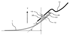
図2は、本発明にかかる車両用ウインドウガラスと仮止めクリップの傾斜面の角度の関係を示す模式図である。図に示したように仮止めクリップ12は車内側周縁部に、傾斜面18が車両用ウインドウガラス1の面内方向に向くように固着される。傾斜面18と平行な直線Q−Q´と基台部12aの垂線P−P´の成す角度をA°とし、車両用ウインドウガラスの中心線上の点Oでの接線(車両用ウインドウガラスの正対したときの平行線)と湾曲した周縁部の仮止めクリップの取り付け位置の点Pでの接線が成す外角の角度をA´°としたとき、傾斜面18を含む直線Q−Q´は車両用ウインドウガラスの中心線上の点Oでの接線の垂線と平行になる。
FIG. 2 is a schematic diagram showing the relationship between the angle of the inclined surface of the vehicle window glass and the temporary fixing clip according to the present invention. As shown in the figure, the temporarily fixing
よって、仮止めクリップ付き車両用ウインドウガラス3の組み付け方向が、直線Q−Q´と平行な矢印Y方向と直線P−P´に平行な矢印Y´方向間の方向であれば、仮止めクリップ12は嵌合用孔と干渉することなく、仮止めクリップ付き車両用ウインドウガラス3を円滑に組み付けることができる。 Therefore, if the assembling direction of the vehicle window glass 3 with a temporary fixing clip is the direction between the arrow Y direction parallel to the straight line QQ ′ and the arrow Y ′ direction parallel to the straight line PP ′, the temporary fixing clip No. 12 can smoothly assemble the window glass 3 with a temporary clip without interfering with the fitting hole.
仮止めクリップの高さL4は、車両の開口枠部と車両用ウインドウガラスの形状によって適宜変更可能であるが、15mm以上であれば、十分な接着剤用の空隙を確保でき好適である。また、仮止めクリップ付き車両用ウインドウガラス3の固定に用いられる接着剤22の塗布高さL6は、仮止めクリップの高さL4より低いことが望ましい。また、LをL6より高くすることにより、輸送時接着剤22が周辺に付着することを低減でき、組み付け時に車両の開口枠部の所望の位置以外への付着も低減できるためである。また、L4が15mmの場合、接着剤22は、L6が12〜14mmの略三角形状で塗布されることが、作業性及び塗布量を適正化するために好適である。これにより、接着剤固化後の車両と車両用ウインドウガラスの間の十分なシール性を確保できる。 The height L4 of the temporary fixing clip can be appropriately changed according to the shape of the opening frame portion of the vehicle and the window glass for the vehicle, but if it is 15 mm or more, a sufficient gap for the adhesive can be secured. Moreover, it is desirable that the application height L6 of the adhesive 22 used for fixing the vehicle window glass 3 with a temporary fixing clip is lower than the height L4 of the temporary fixing clip. Further, by making L higher than L6, it is possible to reduce the adhesion of the adhesive 22 during transportation to the periphery, and it is possible to reduce the adhesion of the opening frame portion of the vehicle to other than the desired position during assembly. When L4 is 15 mm, the adhesive 22 is preferably applied in a substantially triangular shape with L6 of 12 to 14 mm in order to optimize workability and application amount. Thereby, sufficient sealing performance between the vehicle after adhesive solidification and the window glass for vehicles can be secured.
図3は、本発明にかかる仮止めクリップ付き車両用ウインドウガラスの組み付け構造の一例を示す断面図である。仮止めクリップ付き車両用ウインドウガラス3は、矢印Y方向に沿って車両の開口枠部10に組みつけられる。このとき、仮止めクリップ12が嵌合用孔20に挿入され、傾斜部18により所望の位置に誘導され嵌着されて仮止めされる。その結果、車両用ウインドウガラス1が、車両の開口枠部10に対して精度よく位置決めされる。
FIG. 3 is a cross-sectional view showing an example of an assembly structure of a window glass for a vehicle with a temporary fixing clip according to the present invention. The window glass 3 for vehicles with a temporary stop clip is assembled | attached to the
さらに、車両用ウインドウガラス1と開口枠部10は、その隙間に配設された接着剤22によって強固に固着される。接着剤22の車両用ウインドウガラス外周側には接着剤仕切部材24が設けられる。これにより、接着剤22のはみ出しを防止することができ、視界範囲の透明性と意匠性の低下を防止できる。
Furthermore, the
このときの車両用ウインドウガラス1と開口枠部10の間隙L7は、車両の開口枠部と車両用ウインドウガラスの形状によって適宜変更可能であるが、5〜6mmが好適である。また、仮止めクリップの嵌合部12bの高さL3は、L7に対応して定まりL7より高くする必要がある。これは、組み付け後に嵌合部の外周面14が嵌合用孔20に十分な深さで挿入され、隙間なく内接するためである。
The gap L7 between the
前記理由から、L3は5mm以上が好ましく、7mm以上がさらに好ましい。一方、十分な長さの傾斜面18を形成できるように、L3は仮止めクリップの高さL4の半分程度の高さが好適であり、15mm以下が好ましく、10mm以下がさらに好ましい。
For the above reasons, L3 is preferably 5 mm or more, and more preferably 7 mm or more. On the other hand, L3 is preferably about half the height L4 of the temporary fixing clip, preferably 15 mm or less, and more preferably 10 mm or less so that the
また、ここでは仮止めクリップの傾斜面18が車両用ウインドウガラス1の面内方向に向けて固着される例を示したが、本発明はこれに限定されず、車両用ウインドウガラスの湾曲形状に合わせて、面外側に変更することが可能である。
Moreover, although the example in which the
仮止めクリップの傾斜面18の向きを面外側と面内側を組み合わせることにより、組み付け方向に対応した、位置決め誤差の吸収が可能になる。例えば、すべての仮止めクリップを同じ方向に向けて固着した場合、該方向の車外側斜め方向から仮止めクリップ付き車両用ウインドウガラス3を挿入することが容易になる。
By combining the orientation of the
また、仮止めクリップ12に開口枠部10との係着手段を備えてもよい。係着手段は、公知の係着手段を利用可能であるが、弾性爪式、ラッチ式、ソケット式などが好適に利用できる。
Further, the
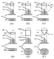
図4は、本発明にかかる仮止めクリップと嵌合用孔の組合せの他の例を示す概念図である。ここまでは、図4(A)に示したような頂頭部16の長径方向片側に傾斜面18を備える例を示したが、図4(B)に示すように頂頭部16の長径方向両側に傾斜部18を備えてもよい。仮止めクリップ12の長径方向で両方向に組み付け誤差の修正が可能になり、組み付け方向の自由度が高まるとともに、組み付け作業時の誤差が自立的に修正され作業性が高まる。また、仮止めクリップの取り違えを減少させることができる。
FIG. 4 is a conceptual diagram showing another example of the combination of the temporary fixing clip and the fitting hole according to the present invention. Up to this point, an example in which the
また、図4(C)に示したように頂頭部16が凸部を形成し、その付け根に形成された肩状部から傾斜部18を備えてもよい。このときL5をL1より小さくするのは前述の通りである。これにより、仮止めクリップ12の体積が減少し、部品が軽量化されるとともに、原料使用量が削減できる。このように、機能に影響のない部分を削除すること、あるいは、中空とすることは、車両の軽量化及び原料コストの低減に効果がある。また、これらの効果は本態様に限定されず他の態様においても同様に適用可能である。
Moreover, as shown in FIG.4 (C), the top 16 may form a convex part, and it may be provided with the
また、図4(D)に示したように傾斜面18は直線状でなく、曲線状でもよく、傾斜面が形成できれば、突起部の形状も半球状、楕円球状など非直線から形成されてもよい。設計自由度が高まるだけでなく、角部が減少し射出成形時の成形性が向上する。
In addition, as shown in FIG. 4D, the
また、図4(E)に示すように頂頭部16の長径方向と短径方向両側に傾斜部18を備えてもよい。仮止めクリップ12の長径方向と短径方向の両方向で組み付け誤差の修正機能を備えた形状となり、短径方向も含めて組み付け方向の自由度がさらに高まるとともに、短径方向においても組み付け作業時の誤差が自立的に修正され作業性が高まる。
Further, as shown in FIG. 4 (E),
また、図4(F)に示すように頂頭部が偏心した略三角柱及び略三角錐形状でもよい。略三角形状であれば、最小数の傾斜面18で長径方向と短径方向の両方向で位置決め精度の高い仮止めクリップを提供できる。また、仮止めクリップ12はさらに、四角形などの多角形やさらに複雑な断面形状を適用することもできる。
Further, as shown in FIG. 4 (F), a substantially triangular prism and a substantially triangular pyramid shape having a decentered top may be used. If it is substantially triangular, a temporary fixing clip having a high positioning accuracy in both the major axis direction and the minor axis direction can be provided with the minimum number of inclined surfaces 18. Further, the
さらに、図に示したように、嵌合用孔20の形状及び寸法は、仮止めクリップの嵌合部12bの寸法L1、L2によって定まる。嵌合用孔20は、長孔形状が、仮止めクリップとの干渉のし難さ、加工の容易さから好適であるが、必ずしもこれに限定されず、本発明の効果を存しない限り、図4(D)に示したように楕円形や図4(F)に示したように三角形でもよく、四角形などの多角形やさらに複雑な形状を適用することもできる。実際の嵌合用孔は、仮止めクリップが挿入可能な程度にL1、L2より若干大きめに隙間を持って形成される。車両用ウインドウガラスの重量にも依存するが、仮止めクリップ嵌合部の外周面16と嵌合用孔20の隙間は0.5〜3mmが好ましく、1〜2mmがさらに好ましい。このとき、仮止めクリップ嵌合部や先端部などに嵌合用孔20からの仮止めクリップの脱落を防止する可撓手段や付勢手段を備えても良い。
Furthermore, as shown in the drawing, the shape and size of the
図5は、本発明にかかる仮止めクリップと嵌合用孔の組合せの応用例を示す概念図である。図5(G)は、図4(B)仮止めクリップの基台部12aに帯状の肉薄部15を備える構成である。肉薄部15は、断面V字状の溝形状を有し、突設された嵌合部12bの付け根から基台部12aの外周縁部へ仮止めクリップの長径及び短径と並行方向に形成される。
FIG. 5 is a conceptual diagram showing an application example of the combination of the temporary fixing clip and the fitting hole according to the present invention. FIG. 5G shows a configuration in which a strip-shaped
図5(H)は、仮止めクリップの長径及び短径方向とは異なる方向に2つの傾斜部18を備え、図5(G)と同様に基台部12aに帯状の肉薄部15を備えた例である。この例のように、傾斜部18は仮止めクリップの長径方向と非平行に形成されてもよく、頂頭部16複数形成されてもよい。傾斜部18を備える複数の組み付け方向で、組み付け誤差の修正が可能になるとともに、仮止めクリップと嵌合用孔の形状の設計自由度が高まる。
FIG. 5 (H) includes two
図6は、図5の仮止めクリップのC−C’断面とウインドウガラスの関係を示す模式図である。図6(A)は、平板な車両用ウインドウガラスに図5(H)の仮止めクリップを取り付けた際の断面、図6(B)は、湾曲した車両用ウインドウガラスに図5(H)の仮止めクリップを取り付けた際の断面である。図6(B)において、仮止めクリップの基台部の当接面17が車両用ウインドウガラス1に追従するには、車両用ウインドウガラスの湾曲に合わせて、基台部12aが変形する必要がる。このとき、基台部12aにV字形状に形成され、他に比べて強度に低い肉薄部15が存在することによって、仮止めクリップの基台部12aが変形しやすくなり、車両用ウインドウガラス1の湾曲への追従性が向上する。
FIG. 6 is a schematic diagram showing the relationship between the C-C ′ cross section of the temporary fixing clip of FIG. 5 and the window glass. 6A is a cross-section when the temporary fixing clip of FIG. 5H is attached to a flat vehicle window glass, and FIG. 6B is a curved window glass of FIG. 5H. It is a cross section at the time of attaching a temporary stop clip. In FIG. 6 (B), in order for the
帯状の肉薄部15は図5に示したように突設された嵌合部12bの付け根と基台部12aの外周縁部とを結んで形成されれば、基台部12aの柔軟性が効果的に高まり、車両用ウインドウガラスへの追従性が向上する。一方、肉薄部15は、必ずしも嵌合部12bの付け根及び基台部の外周縁部まで連続して形成されなくても良い。帯状の肉薄部15は、柔軟性の付与と基台部の強度確保を両立すするために適宜形成することができる。また、肉薄部15は、直線状である必要はなく、曲線状や非連続であっても良い。
If the strip-shaped
図6(C)は、仮止めクリップの当接部17がガラス側に凸の曲面形状を備え、長径方向の両端部の肉厚が薄くなるように形成された例である。これにより、仮止めクリップを湾曲したガラスに取り付ける場合に発生する応力が低減できるとともに、両端部の肉厚が薄いことにより、当接面の曲率より大きな曲率を持つ車両用ウインドウガラスに取り付ける際に、基台部12aの柔軟性がさらに高まり、車両用ウインドウガラスへの追従性の一層の向上が期待できる。当接部17が曲面形状を備え肉厚は一定としてもよく、当接部17は平面で基台部12aの外周側の肉厚が薄くするなど当接面17の形状、帯状の肉薄部15の有無や配置、基台部12aの厚さはそれぞれ独立して設計でき、組み合わせることができることは言うまでもない。
FIG. 6C shows an example in which the
仮止めクリップとの隙間大きすぎるとガタツキが多くなり組み付け時の位置決め精度が低下する。一方、隙間が小さすぎると仮止めクリップが入りにくくなったり、入らなかったりして作業性が低下する。 If the clearance with the temporary fixing clip is too large, rattling will increase and the positioning accuracy during assembly will decrease. On the other hand, if the gap is too small, the temporary fixing clip becomes difficult to enter or does not enter, and workability deteriorates.
本発明における車両用ウインドウガラス11は、平板状のものにも適用可能であるが。湾曲状のものが好適であり、ガラス板内で湾曲の程度が異なるものにさらに好適に適応できる。また、ガラス材料としては、単板ガラスをはじめとし、強化ガラス、合わせガラス等のガラス板、さらに、例えばポリカーボネート類やポリスチレン類等のいわゆるなどの有機透明樹脂材等が用いられてもよい。 Although the window glass 11 for vehicles in this invention is applicable also to a flat form thing. A curved shape is preferable, and it can be more suitably applied to a glass plate having a different degree of bending. Further, as the glass material, a single plate glass, a glass plate such as tempered glass and laminated glass, and a so-called organic transparent resin material such as polycarbonates and polystyrenes may be used.
本発明に仮止めクリップ12の材料には、汎用のエンジニアリングプラスチックが使用可能であるが、POM(Polyoxymethylene Polyacetal)、PBT(Polybutyrene terephthalate)がその射出成形に適した成形性、性能及び価格から好適である。
A general-purpose engineering plastic can be used as the material of the
仮止めクリップは、射出成形によって製造することが可能であり、公知の方法で車両用ウインドウガラスに取り付けることができるが、両面テープやウレタン系接着剤が好適に適用できる。また、加熱や超音波等による溶着や車両用ウインドウガラスのモールを形成する際に同時成形により取り付けられてもよい。 The temporary fixing clip can be manufactured by injection molding and can be attached to the vehicle window glass by a known method, but a double-sided tape or a urethane-based adhesive can be suitably applied. Further, when forming a molding of a window glass for a vehicle or welding by heating or ultrasonic waves, it may be attached by simultaneous molding.
接着剤仕切部材20には、公知のゴム及び発泡材料が使用可能であり、EPDM(Ethylene−Propylene diene terpolymer)が好適である。接着剤22は、公知の高耐久接着剤が利用可能であるが、ウレタン系接着剤が好適である。
For the
本発明は、車両用ウインドウガラスにおいて、特に自動車の固定ウインドウガラスに好適に適用できる。なお、以上において自動車の車両用ウインドウガラスを用いる例を挙げたが、本発明はこれに限定されるものではない。例えば車両の他の開口部、航空機、船舶等の輸送機関やビル、住宅などの建造物等において、板状体を開口枠部に仮止めする際に利用することもできる。 INDUSTRIAL APPLICABILITY The present invention can be suitably applied to a vehicle window glass, particularly to a fixed window glass of an automobile. In addition, although the example which uses the window glass for motor vehicles in the above was given, this invention is not limited to this. For example, it can be used to temporarily fix the plate-like body to the opening frame in other openings of the vehicle, transportation such as airplanes and ships, and buildings such as buildings and houses.
1:車両用ウインドウガラス
3:仮止めクリップ付き車両用ウインドウガラス
10:車両開口枠部
12:仮止めクリップ
12a:基台部
12b:嵌合部
12c:先端部
13:突起部
14:外周面(嵌合部)
15:肉薄部(基台部)
16:頂頭部(先端部)
17:当接面(基台部)
18:傾斜面(先端部)
20:嵌合用孔
22:接着剤
24:接着剤仕切部材
50、51、52:仮止めクリップ
50a、51a:基台部
50b、51b:突起部
50c、52c:外周面(突起部)
60、62:嵌合用孔
1: Vehicle window glass 3: Vehicle window glass with temporary fixing clip 10: Vehicle opening frame portion 12:
15: Thin part (base part)
16: Top (tip)
17: Contact surface (base)
18: Inclined surface (tip)
20: Fitting hole 22: Adhesive 24:
60, 62: holes for fitting
Claims (8)
前記仮止めクリップは、車両用ウインドウガラス表面への固着用の基台部と基台部に突設される嵌合部と嵌合部に連続して形成される先端部を備え、前記嵌合部における嵌合用孔と内接する外周面が基台部に対して垂直であり、前記先端部は、嵌合部の突設中心から偏心して形成された頂頭部を備え、前記頂頭部へ向かい先端に行くにしたがって細くなる先細状であり、その外周に傾斜面を備え、前記車両用ウインドウガラスの中心線上での接線と湾曲した周縁部での接線が成す角度をA°としたとき、前記基台部の垂線に対する前記傾斜面の角度がA〜90°であり、前記先端部が、車両に設けられた前記嵌合用孔に挿入され、前記嵌合部の外周面が前記嵌合用孔に内接して嵌着され車両用ウインドウガラスを位置決めされることができることを特徴とする多車種共用型仮止めクリップ。 A temporary clip that is disposed and positioned at the peripheral edge of a curved vehicle window glass that is assembled to an opening of a vehicle body,
The temporary fixing clip includes a base portion for fixing to the surface of the vehicle window glass, a fitting portion protruding from the base portion, and a tip portion formed continuously to the fitting portion, and the fitting The outer peripheral surface inscribed with the fitting hole in the part is perpendicular to the base part, and the tip part includes a top part formed eccentrically from the projecting center of the fitting part, and the tip part toward the top part When the angle between the tangent line on the center line of the vehicle window glass and the tangent line at the curved peripheral edge is defined as A °, The angle of the inclined surface with respect to the vertical line of the base portion is A to 90 °, the tip portion is inserted into the fitting hole provided in the vehicle, and the outer peripheral surface of the fitting portion is inside the fitting hole. The vehicle window glass can be positioned Multi-car type temporary fixing clip characterized by
仮止めクリップ付き車両用ウインドウガラスは請求項7に記載の仮止めクリップ付き車両用ウインドウガラスであり、
前記嵌合用孔の長径L1が前記仮止めクリップの嵌合部の長径とほぼ等しく、前記嵌合用孔の短径L2が前記仮止めクリップの嵌合部の短径とほぼ等しく、
前記先端部が前記嵌合用孔に挿入されて、前記嵌合部の外周面が前記嵌合用孔に内接して嵌着されて車両用ウインドウガラスを位置決めする
仮止めクリップ付き車両用ウインドウガラスの組み付け構造。 The vehicle window glass with a temporary fixing clip is an assembly structure of a vehicle window glass with a temporary fixing clip that fits into a fitting hole provided in an opening frame portion of the vehicle,
The vehicle window glass with a temporary fixing clip is the vehicle window glass with a temporary fixing clip according to claim 7,
The long diameter L1 of the fitting hole is substantially equal to the long diameter of the fitting portion of the temporary fixing clip, and the short diameter L2 of the fitting hole is substantially equal to the short diameter of the fitting portion of the temporary fixing clip,
Assembling the vehicle window glass with a temporary fixing clip, wherein the tip end portion is inserted into the fitting hole, and the outer peripheral surface of the fitting portion is inscribed and fitted into the fitting hole to position the vehicle window glass. Construction.
Priority Applications (1)
| Application Number | Priority Date | Filing Date | Title |
|---|---|---|---|
| JP2007084410A JP5247053B2 (en) | 2006-03-31 | 2007-03-28 | Temporary clip for window glass for vehicles |
Applications Claiming Priority (3)
| Application Number | Priority Date | Filing Date | Title |
|---|---|---|---|
| JP2006098398 | 2006-03-31 | ||
| JP2006098398 | 2006-03-31 | ||
| JP2007084410A JP5247053B2 (en) | 2006-03-31 | 2007-03-28 | Temporary clip for window glass for vehicles |
Publications (2)
| Publication Number | Publication Date |
|---|---|
| JP2007290692A JP2007290692A (en) | 2007-11-08 |
| JP5247053B2 true JP5247053B2 (en) | 2013-07-24 |
Family
ID=38761721
Family Applications (1)
| Application Number | Title | Priority Date | Filing Date |
|---|---|---|---|
| JP2007084410A Active JP5247053B2 (en) | 2006-03-31 | 2007-03-28 | Temporary clip for window glass for vehicles |
Country Status (1)
| Country | Link |
|---|---|
| JP (1) | JP5247053B2 (en) |
Families Citing this family (1)
| Publication number | Priority date | Publication date | Assignee | Title |
|---|---|---|---|---|
| US7976094B2 (en) * | 2009-03-04 | 2011-07-12 | Zeledyne, Llc | Folding locator pin for glass panels |
Family Cites Families (5)
| Publication number | Priority date | Publication date | Assignee | Title |
|---|---|---|---|---|
| JPH0518914U (en) * | 1991-08-23 | 1993-03-09 | ダイハツ工業株式会社 | Fixed structure for automobile windshield |
| JPH1044764A (en) * | 1996-08-05 | 1998-02-17 | Pop Rivet Fastener Kk | Clip for positioning automobile window glass |
| JP2004144204A (en) * | 2002-10-24 | 2004-05-20 | Three M Innovative Properties Co | Article support |
| JP4226957B2 (en) * | 2003-06-17 | 2009-02-18 | 株式会社東郷製作所 | Wind glass temporary fixing member, wind glass with temporary fixing member, and temporary fixing device for wind glass |
| JP4243841B2 (en) * | 2003-07-22 | 2009-03-25 | 株式会社ニフコ | Wind glass clip |
-
2007
- 2007-03-28 JP JP2007084410A patent/JP5247053B2/en active Active
Also Published As
| Publication number | Publication date |
|---|---|
| JP2007290692A (en) | 2007-11-08 |
Similar Documents
| Publication | Publication Date | Title |
|---|---|---|
| JP5498513B2 (en) | Windshield wiper assembly with optimized wings | |
| KR101269016B1 (en) | Complex partition glass consisting of at least two adjacent glass elements, and method for producing said complex partition glass | |
| JP5043858B2 (en) | Wiper blade with holding body, built-in support and connecting bracket | |
| EP2213519B1 (en) | Joint structure of door edge member | |
| JP5810607B2 (en) | Cowl topside garnish | |
| US9381948B2 (en) | Cowl top cover | |
| JP2010513104A (en) | Wiper blade | |
| US8419105B2 (en) | Sunvisor for vehicle | |
| JP5247053B2 (en) | Temporary clip for window glass for vehicles | |
| JP4793329B2 (en) | Temporary clip for window glass for vehicles | |
| JP4494350B2 (en) | Vehicle windshield mounting structure | |
| JP5122373B2 (en) | Assembled cowl top cover | |
| CN102256855B (en) | Structure of outer hood for rail car | |
| JP2009190621A (en) | Mounting structure of beltline mall | |
| EP1798113A2 (en) | Vehicle molding clip mounting structure | |
| JP2009184487A (en) | Front part air guide structure for automobile | |
| JP4420403B2 (en) | Cowl structure | |
| JP5216756B2 (en) | Connecting structure for vehicle molding | |
| JP2010115985A (en) | Seal member of automobile | |
| US20120001446A1 (en) | Trim component comprising fastening means | |
| JP2010163057A (en) | Wiper blade | |
| KR20210144757A (en) | Vehicle window structures, vehicle window decoration parts and vehicles | |
| JP2005088733A (en) | Attachment structure of plate conditioned body for window to window frame and plate conditioned body for window having base | |
| JP2009262714A (en) | Mounting structure of air dam skirt for vehicle | |
| JP2013052726A (en) | Positioning structure body of vehicle panel |
Legal Events
| Date | Code | Title | Description |
|---|---|---|---|
| A621 | Written request for application examination |
Free format text: JAPANESE INTERMEDIATE CODE: A621 Effective date: 20090904 |
|
| A977 | Report on retrieval |
Free format text: JAPANESE INTERMEDIATE CODE: A971007 Effective date: 20110728 |
|
| A131 | Notification of reasons for refusal |
Free format text: JAPANESE INTERMEDIATE CODE: A131 Effective date: 20110823 |
|
| A521 | Request for written amendment filed |
Free format text: JAPANESE INTERMEDIATE CODE: A523 Effective date: 20111020 |
|
| A02 | Decision of refusal |
Free format text: JAPANESE INTERMEDIATE CODE: A02 Effective date: 20120313 |
|
| A521 | Request for written amendment filed |
Free format text: JAPANESE INTERMEDIATE CODE: A523 Effective date: 20120612 |
|
| A911 | Transfer to examiner for re-examination before appeal (zenchi) |
Free format text: JAPANESE INTERMEDIATE CODE: A911 Effective date: 20120801 |
|
| A912 | Re-examination (zenchi) completed and case transferred to appeal board |
Free format text: JAPANESE INTERMEDIATE CODE: A912 Effective date: 20121005 |
|
| A61 | First payment of annual fees (during grant procedure) |
Free format text: JAPANESE INTERMEDIATE CODE: A61 Effective date: 20130409 |
|
| R151 | Written notification of patent or utility model registration |
Ref document number: 5247053 Country of ref document: JP Free format text: JAPANESE INTERMEDIATE CODE: R151 |
|
| FPAY | Renewal fee payment (event date is renewal date of database) |
Free format text: PAYMENT UNTIL: 20160419 Year of fee payment: 3 |
|
| S533 | Written request for registration of change of name |
Free format text: JAPANESE INTERMEDIATE CODE: R313533 |
|
| R350 | Written notification of registration of transfer |
Free format text: JAPANESE INTERMEDIATE CODE: R350 |
|
| R250 | Receipt of annual fees |
Free format text: JAPANESE INTERMEDIATE CODE: R250 |
|
| R250 | Receipt of annual fees |
Free format text: JAPANESE INTERMEDIATE CODE: R250 |
|
| R250 | Receipt of annual fees |
Free format text: JAPANESE INTERMEDIATE CODE: R250 |
|
| R250 | Receipt of annual fees |
Free format text: JAPANESE INTERMEDIATE CODE: R250 |
|
| R250 | Receipt of annual fees |
Free format text: JAPANESE INTERMEDIATE CODE: R250 |
|
| R250 | Receipt of annual fees |
Free format text: JAPANESE INTERMEDIATE CODE: R250 |