JP5122373B2 - Assembled cowl top cover - Google Patents
Assembled cowl top cover Download PDFInfo
- Publication number
- JP5122373B2 JP5122373B2 JP2008140744A JP2008140744A JP5122373B2 JP 5122373 B2 JP5122373 B2 JP 5122373B2 JP 2008140744 A JP2008140744 A JP 2008140744A JP 2008140744 A JP2008140744 A JP 2008140744A JP 5122373 B2 JP5122373 B2 JP 5122373B2
- Authority
- JP
- Japan
- Prior art keywords
- windshield glass
- top cover
- cowl top
- fixing
- weather strip
- Prior art date
- Legal status (The legal status is an assumption and is not a legal conclusion. Google has not performed a legal analysis and makes no representation as to the accuracy of the status listed.)
- Active
Links
- 239000011521 glass Substances 0.000 claims description 51
- 230000037431 insertion Effects 0.000 claims description 5
- 238000003780 insertion Methods 0.000 claims description 5
- 238000000465 moulding Methods 0.000 description 5
- 230000008878 coupling Effects 0.000 description 2
- 238000010168 coupling process Methods 0.000 description 2
- 238000005859 coupling reaction Methods 0.000 description 2
- 238000004519 manufacturing process Methods 0.000 description 2
- XLYOFNOQVPJJNP-UHFFFAOYSA-N water Substances O XLYOFNOQVPJJNP-UHFFFAOYSA-N 0.000 description 2
- 239000000853 adhesive Substances 0.000 description 1
- 230000001070 adhesive effect Effects 0.000 description 1
Images


Classifications
-
- B—PERFORMING OPERATIONS; TRANSPORTING
- B62—LAND VEHICLES FOR TRAVELLING OTHERWISE THAN ON RAILS
- B62D—MOTOR VEHICLES; TRAILERS
- B62D25/00—Superstructure or monocoque structure sub-units; Parts or details thereof not otherwise provided for
- B62D25/08—Front or rear portions
- B62D25/081—Cowls
-
- B—PERFORMING OPERATIONS; TRANSPORTING
- B62—LAND VEHICLES FOR TRAVELLING OTHERWISE THAN ON RAILS
- B62D—MOTOR VEHICLES; TRAILERS
- B62D25/00—Superstructure or monocoque structure sub-units; Parts or details thereof not otherwise provided for
- B62D25/08—Front or rear portions
-
- B—PERFORMING OPERATIONS; TRANSPORTING
- B60—VEHICLES IN GENERAL
- B60R—VEHICLES, VEHICLE FITTINGS, OR VEHICLE PARTS, NOT OTHERWISE PROVIDED FOR
- B60R13/00—Elements for body-finishing, identifying, or decorating; Arrangements or adaptations for advertising purposes
- B60R13/04—External Ornamental or guard strips; Ornamental inscriptive devices thereon
Description
本発明は、組立式カウルトップカバーに関し、詳しくは自動車車両のフードとウインドシールドガラスとの間に設けられたカウル溝を覆うためのカウルトップカバーについて、カウルトップカバー本体の端部に、ウインドシールドガラスを下方から支持するように着脱可能に設けられた複数の固定用フックを配した組立式のカウルトップカバーに関する。 More particularly, the present invention relates to a cowl top cover for covering a cowl groove provided between a hood of an automobile and a windshield glass. The present invention relates to an assembly type cowl top cover provided with a plurality of fixing hooks detachably provided so as to support glass from below.
一般に、自動車車両のフードとウインドシールドガラスとの間にはカウル溝が設けられ、そのカウル溝を覆うためにカウルトップカバーが設けられている〔例えば、特許文献1、特許文献2参照〕。カウルトップカバーの取付け構造として、カウルトップカバーの後端部に形成した係合溝を有するクリップ部でフロントガラスの下端部を支持するカウルトップ構造〔特許文献3参照〕や、カウルトップカバーの後端部にフロントガラスの下端縁を支持する切欠け受け面を設け、フロントガラスと切欠け受け面とを接着剤にてカウルトップパネルに固定されたカウルトップ構造〔特許文献4参照〕等が報告されている。 Generally, a cowl groove is provided between a hood of an automobile vehicle and a windshield glass, and a cowl top cover is provided to cover the cowl groove [see, for example, Patent Document 1 and Patent Document 2]. As a cowl top cover mounting structure, a cowl top structure (see Patent Document 3) in which a lower end portion of a windshield is supported by a clip portion having an engaging groove formed at a rear end portion of the cowl top cover, or a rear of the cowl top cover. Reported is a cowl top structure (see Patent Document 4) in which a notch receiving surface that supports the lower edge of the windshield is provided at the end, and the windshield and the notch receiving surface are fixed to the cowl top panel with an adhesive. Has been.
図1には、従来のカウルトップカバーの典型的な構造を、車両に取り付けられた状態の断面図で示している。
カウルトップカバー100は、一端がフード10側のカウルアンダーパネル50に取り付けられ、他端がウインドシールドガラス120を支持しており、これによりカウル溝30を覆っている。また、カウルトップカバー100のフード10側では、フード10との水密のためにウェザーストリップ130が設けられ、ウインドシールドガラス120側ではウインドシールドガラス120との水密のためにウェザーストリップ121が嵌着されている。
FIG. 1 is a sectional view showing a typical structure of a conventional cowl top cover attached to a vehicle.
One end of the
カウルトップカバー100においては、そのウインドシールドガラス120側端部に、固定用フック110が一体に設けられており、ウインドシールドガラス120の一端が延長されて、固定用フック110とウェザーストリップ121に挟まれて安定に位置している。
In the
固定用フック110は、ウインドシールドガラス120が傾斜して延長できるように、所定の傾斜角をなして成形されなければならない。それ故、固定用フック110が傾斜角を持つようにカウルトップカバー100と固定用フック110を一体成形するには、図1に示すようにカウルトップカバー100を成形する金型(上型および下型)の移動方向(A)に対して、傾斜角が保たれる移動方向(B)に移動することが出来る別の側面金型が必要となるので、カウルトップカバー100を成形する金型は、大きく、形状が複雑となる。従って、金型の作成、さらに成型に面倒な作業を必要とし、作業時間も長くなり、コストが増加するという問題があった。さらに、車種毎に別途の金型を用意しなければならないことが多く、その面でもコストアップとなっていた。
The
上記問題点を解決すべく、本発明の目的は、カウルトップカバーを成形する金型を小さくすることができる組立式カウルトップカバーを提供することにある。 In order to solve the above-described problems, an object of the present invention is to provide an assembly-type cowl top cover that can reduce a mold for molding the cowl top cover.
上記目的を達成するために、本発明は、自動車のフードとウインドシールドガラスとの間に位置してカウル溝を覆うためのカウルトップカバーであって、a)ウインドシールドガラス側端部に固定溝が設けられると共に、一端がフード側車体に結合し、他端がウインドシールドガラスに接続するカウルトップカバー本体と、b)カウルトップカバー本体のウインドシールドガラス側端部にあって、ウインドシールドガラスを下方から支持するように着脱可能に設けられた複数の固定用フックとで構成されて、
固定用フックは、その上端に固定溝に嵌合される固定突起と、ウェザーストリップ支持部の下側からさらにウインドシールドガラス側に突設されたウインドシールドガラス支持部を有して、ウインドシールドガラス支持部には、ウェザーストリップ支持部とは反対側端部にあってウインドシールドガラスの下面に接触するフック突起と、中央部にウェザーストリップが挿入されるウェザーストリップ挿入孔が設けられて構成されている。
In order to achieve the above object, the present invention provides a cowl top cover for covering a cowl groove located between a hood of an automobile and a windshield glass, and a) a fixed groove at a side end portion of the windshield glass. together is provided having one end attached to the hood side vehicle body, and the cowl top cover body and the other end is connected to the windshield glass, b) in the windshield glass side end portion of the cowl top cover body, a windshield glass It is composed of a plurality of fixing hooks that are detachably provided so as to be supported from below .
The fixing hook has a fixing projection fitted into the fixing groove at the upper end thereof, and a windshield glass support portion protruding from the lower side of the weatherstrip support portion to the windshield glass side. The support portion is provided with a hook protrusion that contacts the lower surface of the windshield glass at the end opposite to the weather strip support portion, and a weather strip insertion hole into which the weather strip is inserted at the center portion. Yes.
固定突起には、ウインドシールドガラス側に、ウェザーストリップを支持するためのウェザーストリップ支持部が突設されるのがよい。 The fixing projection is preferably provided with a weather strip support portion for supporting the weather strip on the windshield glass side.
本発明によれば、ウインドシールドガラスとカウルトップカバーとの連結部に、カバー本体とは別途の部品として固定用フックを設けており、これによりカバー本体と固定用フックはそれぞれ別に成形できるので、カウルトップカバーを成形するための金型の構造を単純にすることができ、金型の製作費用はもちろん、カウルトップカバーの成形費用をも節減することができる。
また、本発明によれば、同一の固定用フックを多様な車種のカウルトップカバーに共用として使用することができるので、部品製造コストを節減することができ、カバー本体と固定用フックを成形する金型をそれぞれ別に備えるので、実行上の自由度を高めることができる。
According to the present invention, the connecting portion between the windshield glass and the cowl top cover is provided with a fixing hook as a separate component from the cover main body, so that the cover main body and the fixing hook can be molded separately, The structure of the mold for molding the cowl top cover can be simplified, and the molding cost of the cowl top cover can be reduced as well as the production cost of the mold.
In addition, according to the present invention, the same fixing hook can be used commonly for a cowl top cover of various types of vehicles, so that the manufacturing cost of parts can be reduced, and the cover body and the fixing hook are formed. Since each mold is provided separately, the degree of freedom in execution can be increased.
以下に添付図面を参照しながら好適な実施の形態の例を挙げて、本発明を詳細に説明する。
図2は、本発明に係る組立式カウルトップカバーのカバー本体を下方からみての斜視図であり、図3は、固定用フックの斜視図であり、図4は、カバー本体と固定用フックとの結合を示す斜視図であり、図5は、図4に示した結合状態にウェザーストリップが挿入されて後、A−A線に沿った断面図である。
Hereinafter, the present invention will be described in detail by way of examples of preferred embodiments with reference to the accompanying drawings.
2 is a perspective view of the cover body of the assembly type cowl top cover according to the present invention as viewed from below, FIG. 3 is a perspective view of the fixing hook, and FIG. 4 is a perspective view of the cover main body, the fixing hook, and FIG. FIG. 5 is a cross-sectional view taken along the line AA after the weather strip has been inserted into the coupled state shown in FIG. 4.
本発明の組立式カウルトップカバーは、図1で説明したようにフード10とウインドシールドガラス120との間に設けられたカウル溝30を覆うためのものであり、カバー本体200と、ウインドシールドガラス120側の端部にあってウインドシールドガラス120を下方から支持する複数の固定用フック210とから構成される。
The assembly type cowl top cover of the present invention is for covering the
カバー本体200と固定用フック210を一体化させるために、カバー本体200のウインドシールドガラス120側端部には固定溝201が設けられ、固定溝201に固定用フック210の一部が嵌込まれる。
In order to integrate the cover
固定用フック210は、図3にその構造を示したように、上端に固定突起212が設けられ、この固定突起212がカバー本体200の固定溝201に嵌合されることになる。このとき、固定突起212と固定溝201は嵌合状態において互いに密になって動きがないようにするため、それぞれの断面が略四角状にすることが好ましい。
As shown in FIG. 3, the
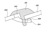
固定突起212において固定溝201と嵌合しない部分には、ウェザーストリップ支持部213が突設され、ウェザーストリップ121が挿入されたときにこれを前方から支持できるようにする。図5に示すように、ウェザーストリップ支持部213は、固定突起212からウインドシールドガラス120側に突出した四角形状であって、ウェザーストリップ121を車両の前方から支持する役割を果たす。そして、ウェザーストリップ121は、ウインドシールドガラス120とウェザーストリップ支持部213との間に固着される。
A weather
また、固定用フック210の側部には、ウインドシールドガラス120を下方から支持するウインドシールドガラス支持部214が突設される。このとき、ウインドシールドガラス支持部214の端部にフック突起216を設けると、ウインドシールドガラス120の滑りを防止することができる。また、ウインドシールドガラス支持部214の中央部には、ウェザーストリップ121が挿入されるウェザーストリップ挿入孔215が設けられることが好ましい。
In addition, a windshield
以上の構造により、カバー本体200と固定用フック210、さらに固定用フック210を介してウインドシールドガラス120が、互いに安定した状態で結合される。
With the above structure, the
次に、このように構成された本発明についてさらに詳細に説明する。
まず、カバー本体200のウインドシールドガラス120側端部に設けられた固定溝201の内部に固定突起212を挿入し、カバー本体200と固定用フック210を結合させる。固定溝201と固定突起212は、それぞれ断面が略四角状をしているので、互いの動きが抑えられ、組立てた構造が安定する。カバー本体200と固定用フック210との結合が完了すると、固定用フック210がカバー本体200の端部に突出するようになり、固定用フック210のウインドシールドガラス支持部214が、ウインドシールドガラス120の傾斜角に合せた傾斜にして設けられる。
Next, the present invention configured as described above will be described in more detail.
First, the
この状態でウインドシールドガラス120を結合させ、ウェザーストリップ121をウインドシールドガラス120の上方からウェザーストリップ挿入孔215に挿着させる。
In this state, the
以上、本発明の実施の形態を例に、図示および説明したが、本発明は、特許請求の範囲に記載した本発明の技術的思想から逸脱しない範囲内において、様々に改良および変形を加え得ることはいうまでもない。 The embodiments of the present invention have been illustrated and described above, but the present invention can be variously improved and modified without departing from the technical idea of the present invention described in the claims. Needless to say.
本発明によれば、カバー本体200と固定用フック210は、それぞれ別途の部品として成形した後にカバー本体200の端部に固定用フック210を結合させるので、カウルトップカバーを成形するための金型は、単純な構造となり、その大きさを小さくすることができる。
また、固定用フック210を別途の部品として成形するので、固定用フック210の標準化が可能であり、複数の車種に共通に使用することができる利点も出てくる。
According to the present invention, the cover
Further, since the
10;フード
30;カウル溝
50;カウルアンダーパネル
100;カウルトップカバー
110;固定用フック
120;ウインドシールドガラス
121;(ウインドシールドガラスとの水密のための)ウェザーストリップ
130;(フードとの水密のための)ウェザーストリップ
200;カウルトップカバー本体
201;固定溝
210;固定用フック
212;固定突起
213;ウェザーストリップ支持部
214;ウインドシールドガラス支持部
215;ウェザーストリップ挿入孔
216;フック突起
10;
Claims (2)
前記固定用フックは、その上端に前記固定溝に嵌合される固定突起と、前記ウェザーストリップ支持部の下側からさらに前記ウインドシールドガラス側に突設されたウインドシールドガラス支持部を有して、
前記ウインドシールドガラス支持部には、前記ウェザーストリップ支持部とは反対側端部にあって前記ウインドシールドガラスの下面に接触するフック突起と、中央部にウェザーストリップが挿入されるウェザーストリップ挿入孔が設けられていることを特徴とする組立式カウルトップカバー。 A) Located between the windshield glass and the windshield glass , a) A fixing groove is provided at the windshield glass side end , one end is coupled to the hood side body, and the other end is connected to the windshield glass. composed of a cowl top cover body, b) in the said windshield glass side end portion of the cowl top cover body, a plurality of fixing hooks provided detachably to support the windshield glass from below A cowl top cover covering a cowl groove between the hood and the windshield glass,
The fixing hook has a fixing projection fitted into the fixing groove at an upper end thereof, and a windshield glass support portion protruding from the lower side of the weather strip support portion to the windshield glass side. ,
The windshield glass support portion has a hook protrusion at an end opposite to the weatherstrip support portion that contacts the lower surface of the windshield glass, and a weatherstrip insertion hole into which the weatherstrip is inserted in the center portion. An assembly type cowl top cover characterized by being provided .
Applications Claiming Priority (2)
| Application Number | Priority Date | Filing Date | Title |
|---|---|---|---|
| KR10-2007-0131007 | 2007-12-14 | ||
| KR1020070131007A KR100882686B1 (en) | 2007-12-14 | 2007-12-14 | Assembly type cowl top cover and producing method thereof |
Publications (2)
| Publication Number | Publication Date |
|---|---|
| JP2009143530A JP2009143530A (en) | 2009-07-02 |
| JP5122373B2 true JP5122373B2 (en) | 2013-01-16 |
Family
ID=40680209
Family Applications (1)
| Application Number | Title | Priority Date | Filing Date |
|---|---|---|---|
| JP2008140744A Active JP5122373B2 (en) | 2007-12-14 | 2008-05-29 | Assembled cowl top cover |
Country Status (5)
| Country | Link |
|---|---|
| US (1) | US7918494B2 (en) |
| JP (1) | JP5122373B2 (en) |
| KR (1) | KR100882686B1 (en) |
| CN (1) | CN101456431B (en) |
| DE (1) | DE102008047917B4 (en) |
Families Citing this family (4)
| Publication number | Priority date | Publication date | Assignee | Title |
|---|---|---|---|---|
| US8757706B2 (en) | 2010-09-28 | 2014-06-24 | Honda Motor Co., Ltd. | Structure for positioning cowl top for vehicle |
| CN102582532B (en) * | 2012-02-29 | 2014-04-16 | 浙江吉利汽车研究院有限公司 | Buckle connecting structure |
| JP2015104995A (en) * | 2013-11-29 | 2015-06-08 | 日本プラスト株式会社 | Cowl part structure of vehicle |
| US9162552B2 (en) * | 2014-03-05 | 2015-10-20 | Fca Us Llc | Self-locating water-soluble glass support |
Family Cites Families (16)
| Publication number | Priority date | Publication date | Assignee | Title |
|---|---|---|---|---|
| DE3442299C1 (en) * | 1984-11-20 | 1986-02-06 | Daimler-Benz Ag, 7000 Stuttgart | Adjustment and fixing device for bonded-in windows |
| US4912895A (en) * | 1987-12-28 | 1990-04-03 | Ford Motor Company | Adjustable spacer |
| US5013077A (en) * | 1988-11-21 | 1991-05-07 | Automotive Moulding Company | Adjustable spacers for supporting front window glass in an automobile |
| US4921297A (en) * | 1988-11-21 | 1990-05-01 | Automotive Moulding Company | Adjustable spacers for supporting front window glass in an automobile |
| JP2848026B2 (en) * | 1991-06-21 | 1999-01-20 | 豊田合成株式会社 | Cowl louver |
| KR0140757Y1 (en) | 1994-06-27 | 1999-04-01 | 전성원 | Extendible car seat |
| US5531496A (en) * | 1994-07-28 | 1996-07-02 | Saturn Corporation | Automotive glass enclosure retaining fixture |
| JP4174881B2 (en) * | 1998-11-18 | 2008-11-05 | 日本プラスト株式会社 | Car cowl top cover structure |
| US6151847A (en) * | 1999-06-04 | 2000-11-28 | Daimlerchrysler Corporation | Window glass spacer |
| KR100428388B1 (en) * | 2001-07-21 | 2004-04-28 | 현대자동차주식회사 | Cowl top cover upper end support means of automobile |
| JP3969121B2 (en) * | 2002-02-26 | 2007-09-05 | 豊田合成株式会社 | Pedestrian protection device |
| US6957849B2 (en) * | 2004-01-02 | 2005-10-25 | Ford Global Technologies, Llc | Windshield stop for cowl vent grille attachment |
| JP4476118B2 (en) * | 2004-07-27 | 2010-06-09 | 日本プラスト株式会社 | Cowl top cover |
| US7147274B2 (en) * | 2004-09-03 | 2006-12-12 | Nissan Technical Center North America | Windshield spacer |
| JP4704786B2 (en) * | 2005-03-31 | 2011-06-22 | 日本プラスト株式会社 | Cowl top cover mounting structure |
| JP2009083593A (en) * | 2007-09-28 | 2009-04-23 | Nippon Plast Co Ltd | Cowl top cover, and windshield glass fitting structure |
-
2007
- 2007-12-14 KR KR1020070131007A patent/KR100882686B1/en active IP Right Grant
-
2008
- 2008-05-29 JP JP2008140744A patent/JP5122373B2/en active Active
- 2008-09-19 DE DE102008047917.9A patent/DE102008047917B4/en active Active
- 2008-09-26 CN CN2008101714304A patent/CN101456431B/en active Active
- 2008-09-26 US US12/238,658 patent/US7918494B2/en active Active
Also Published As
| Publication number | Publication date |
|---|---|
| US7918494B2 (en) | 2011-04-05 |
| CN101456431A (en) | 2009-06-17 |
| CN101456431B (en) | 2012-05-30 |
| JP2009143530A (en) | 2009-07-02 |
| US20090152897A1 (en) | 2009-06-18 |
| DE102008047917B4 (en) | 2017-03-09 |
| KR100882686B1 (en) | 2009-02-06 |
| DE102008047917A1 (en) | 2009-06-18 |
Similar Documents
| Publication | Publication Date | Title |
|---|---|---|
| CN1958345B (en) | Bumper fixture and bumper mounting structure | |
| KR101196174B1 (en) | Wiper blade comprising a support frame, an internal stiffening member and a connecting element | |
| JP2009507711A (en) | Fixing device between wiper blade and windscreen wiper blade holder | |
| JP4704786B2 (en) | Cowl top cover mounting structure | |
| JP5122373B2 (en) | Assembled cowl top cover | |
| JP5994646B2 (en) | Mounting structure for vehicle interior parts | |
| JP4722611B2 (en) | Fender cover structure | |
| JP2010036641A (en) | Windshield support part structure | |
| JP4852462B2 (en) | Car cowl structure | |
| JP2007168654A (en) | Vehicle front structure | |
| JP2006290219A (en) | Wiper blade | |
| JP2006192975A (en) | Front fender mounting part structure of cover member | |
| JP5437239B2 (en) | Configuration to fix the automobile body surface liner near the window glass | |
| US10654526B2 (en) | Vehicle body structure | |
| JP2018047858A (en) | Cowl top cover | |
| JP2006168679A (en) | Roof structure of vehicle | |
| EP2226210B1 (en) | Weatherstrip bar for automobile doors | |
| JP4622529B2 (en) | Roof molding mounting structure | |
| JP5352163B2 (en) | Automotive visor and its mounting structure | |
| CN216833137U (en) | Side wall window assembly and vehicle | |
| JP2005247025A (en) | Attaching structure of weather strip | |
| KR20160055323A (en) | Assembling structure of cowl top cover and the assembling method thereof | |
| JP4177806B2 (en) | Vehicle roof structure | |
| CN217917583U (en) | Automobile door and automobile | |
| JP5516281B2 (en) | Side visor mounting structure |
Legal Events
| Date | Code | Title | Description |
|---|---|---|---|
| A621 | Written request for application examination |
Free format text: JAPANESE INTERMEDIATE CODE: A621 Effective date: 20100604 |
|
| A977 | Report on retrieval |
Free format text: JAPANESE INTERMEDIATE CODE: A971007 Effective date: 20120426 |
|
| A131 | Notification of reasons for refusal |
Free format text: JAPANESE INTERMEDIATE CODE: A131 Effective date: 20120501 |
|
| A521 | Request for written amendment filed |
Free format text: JAPANESE INTERMEDIATE CODE: A523 Effective date: 20120730 |
|
| TRDD | Decision of grant or rejection written | ||
| A01 | Written decision to grant a patent or to grant a registration (utility model) |
Free format text: JAPANESE INTERMEDIATE CODE: A01 Effective date: 20120925 |
|
| A01 | Written decision to grant a patent or to grant a registration (utility model) |
Free format text: JAPANESE INTERMEDIATE CODE: A01 |
|
| A61 | First payment of annual fees (during grant procedure) |
Free format text: JAPANESE INTERMEDIATE CODE: A61 Effective date: 20121024 |
|
| FPAY | Renewal fee payment (event date is renewal date of database) |
Free format text: PAYMENT UNTIL: 20151102 Year of fee payment: 3 |
|
| R150 | Certificate of patent or registration of utility model |
Free format text: JAPANESE INTERMEDIATE CODE: R150 Ref document number: 5122373 Country of ref document: JP Free format text: JAPANESE INTERMEDIATE CODE: R150 |
|
| R250 | Receipt of annual fees |
Free format text: JAPANESE INTERMEDIATE CODE: R250 |
|
| R250 | Receipt of annual fees |
Free format text: JAPANESE INTERMEDIATE CODE: R250 |
|
| R250 | Receipt of annual fees |
Free format text: JAPANESE INTERMEDIATE CODE: R250 |
|
| R250 | Receipt of annual fees |
Free format text: JAPANESE INTERMEDIATE CODE: R250 |
|
| R250 | Receipt of annual fees |
Free format text: JAPANESE INTERMEDIATE CODE: R250 |
|
| R250 | Receipt of annual fees |
Free format text: JAPANESE INTERMEDIATE CODE: R250 |
|
| R250 | Receipt of annual fees |
Free format text: JAPANESE INTERMEDIATE CODE: R250 |
|
| R250 | Receipt of annual fees |
Free format text: JAPANESE INTERMEDIATE CODE: R250 |
|
| R250 | Receipt of annual fees |
Free format text: JAPANESE INTERMEDIATE CODE: R250 |