JP5246775B2 - Screen printing machine - Google Patents
Screen printing machine Download PDFInfo
- Publication number
- JP5246775B2 JP5246775B2 JP2008334365A JP2008334365A JP5246775B2 JP 5246775 B2 JP5246775 B2 JP 5246775B2 JP 2008334365 A JP2008334365 A JP 2008334365A JP 2008334365 A JP2008334365 A JP 2008334365A JP 5246775 B2 JP5246775 B2 JP 5246775B2
- Authority
- JP
- Japan
- Prior art keywords
- screen
- squeegee
- protrusion
- plate
- printing machine
- Prior art date
- Legal status (The legal status is an assumption and is not a legal conclusion. Google has not performed a legal analysis and makes no representation as to the accuracy of the status listed.)
- Active
Links
- 238000007650 screen-printing Methods 0.000 title claims description 12
- 230000002265 prevention Effects 0.000 claims description 28
- 238000007639 printing Methods 0.000 claims description 16
- 239000011248 coating agent Substances 0.000 claims description 10
- 238000001125 extrusion Methods 0.000 description 4
- 229910000679 solder Inorganic materials 0.000 description 4
- 239000000758 substrate Substances 0.000 description 4
- 238000011144 upstream manufacturing Methods 0.000 description 3
- 238000012986 modification Methods 0.000 description 2
- 230000004048 modification Effects 0.000 description 2
- 238000004140 cleaning Methods 0.000 description 1
- 239000012530 fluid Substances 0.000 description 1
- 238000009434 installation Methods 0.000 description 1
- 239000000463 material Substances 0.000 description 1
Images


Description
本発明は、スクリーンのスクリーン板上の塗布剤をスキージを移動させることにより、前記スクリーン板に開設された印刷パターン孔を介してプリント基板上に塗布するスクリーン印刷機に関する。 The present invention relates to a screen printing machine that applies a coating agent on a screen plate of a screen onto a printed board through a printing pattern hole formed in the screen plate by moving a squeegee.
この種のスクリーン印刷機は、例えば特許文献1などに開示されているように、塗布剤が側方へはみ出すのを防止するために、スキージの両側部にはみ出し防止体を設けている。
しかし、スキージの両側部にはみ出し防止体を取り付けているので、スキージの進行側や、スキージとはみ出し防止体との間に塗布剤が溜まりやすく、スキージやはみ出し防止体を清掃する場合には、スクリーン印刷機からスキージ及びはみ出し防止体を備えたスキージユニットを外して行わねばならず、作業者にとって甚だ面倒な作業となっていた。 However, since anti-extrusion bodies are attached to both sides of the squeegee, it is easy for the coating agent to accumulate on the traveling side of the squeegee and between the squeegee and the extrude prevention body. The squeegee and the squeegee unit provided with the protrusion prevention body have to be removed from the printing press, which is a troublesome work for the operator.
そこで本発明は、スキージやはみ出し防止体の清掃が簡単に行えるようにすることを目的とする。 Accordingly, an object of the present invention is to enable easy cleaning of a squeegee and a protrusion prevention body.
このため第1の発明は、スクリーンのスクリーン板上の塗布剤をスキージを移動させることにより、前記スクリーン板に開設された印刷パターン孔を介してプリント基板上に塗布するスクリーン印刷機において、間隔調整部材により前記スクリーン板を支持する対向するスクリーン枠に、前記塗布剤の側方へのはみ出しを防止するはみ出し防止板を高さ調整部材により上下方向に調整可能に設けたはみ出し防止体の両端部を夫々移動可能に取り付けたことを特徴とする。 For this reason, in the first aspect of the present invention, in the screen printing machine that applies the coating agent on the screen plate of the screen to the printed circuit board through the printing pattern hole established in the screen plate by moving the squeegee, the interval adjustment is performed. Both ends of the anti-extrusion body are provided on the opposing screen frame that supports the screen plate by a member and is provided with an anti-extrusion plate that prevents the coating agent from protruding laterally by a height adjusting member. It is characterized in that each is attached so as to be movable.
第2の発明は、第1の発明において、前記はみ出し防止板をその長さ方向の異なる位置で複数の前記高さ調整部材により前記はみ出し防止体に固定したことを特徴とする。 According to a second invention, in the first invention, the protrusion preventing plate is fixed to the protrusion preventing body by a plurality of the height adjusting members at different positions in the length direction .
本発明は、スキージやはみ出し防止体の清掃が簡単に行えるようにすることができる。 The present invention can easily clean the squeegee and the protrusion preventing body.
以下、本発明の具体的な実施形態を図面を参照しながら説明する。スクリーン印刷機は、図示しない上流側装置から搬送されてくるプリント基板Pの上面にチップ状電子部品が装着されるように所望のパターンに塗布剤としての図示しない流動物である半田ペーストを塗布する。 Hereinafter, specific embodiments of the present invention will be described with reference to the drawings. The screen printing machine applies a solder paste, which is a fluid (not shown), as a coating agent to a desired pattern so that chip-shaped electronic components are mounted on the upper surface of the printed circuit board P conveyed from an upstream device (not shown). .
前記プリント基板Pは載置台(図示せず)上に、位置決め機構(図示せず)により位置決めした状態で載置される。この載置台は移動台により上下移動機構により上下移動され、この移動台は移動機構により水平方向に移動可能であり、前記上流側装置からプリント基板Pを受取って載置台上に位置決めする位置決めステーションから印刷ステーションまで移動される。 The printed circuit board P is placed on a placement table (not shown) in a state of being positioned by a positioning mechanism (not shown). This mounting table is moved up and down by a vertical movement mechanism by a moving table, and this moving table is movable in the horizontal direction by the moving mechanism, and receives a printed circuit board P from the upstream device and positions it on the mounting table. Moved to the printing station.
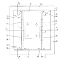
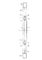
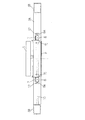
スクリーンの平面図である図1、図1のA−A断面図である図2、図1のB−B断面図である図3において、1はスクリーン支持ユニットにより支持されるスクリーンで、前記プリント基板Pの所望の回路パターンに対応して穿設された印刷パターン孔(開口)が設けられたスクリーン板2と、該スクリーン板2を囲むスクリーン枠3とから構成される。
1 is a plan view of the screen, FIG. 2 is a sectional view taken along the line AA of FIG. 1, and FIG. 3 is a sectional view taken along the line BB of FIG. 1, wherein 1 is a screen supported by a screen support unit. The
前記スクリーン1のスクリーン枠3は、一方の対向する一対のスクリーン枠3A、3Aと他方の対向する一対のスクリーン枠3B、3Bとから平面視矩形状を呈するように形成される。
The screen frame 3 of the screen 1 is formed to have a rectangular shape in plan view from one pair of
そして、一対のスキージ5が交互に下降して一対のスクリーン枠3A、3A間で往復移動機構により前後方向(図1の紙面の上下方向)に移動する。スクリーン1において、一対のはみ出し防止体8が間隔調整部材により、相互の間隔が調整できる。
Then, the pair of
即ち、スクリーン枠3A、3Aの対向する内側面には横長の水平方向に延びるガイド6が形成され、はんだペーストの側方へのはみ出しを防止するはみ出し防止板7を備えた一対のはみ出し防止体8を水平方向に移動させる。また、前記各ガイド6はスクリーン枠3Aの内側面に収納空間Sを形成するように、且つこの空間Sを形成する前面9には横長の案内調整口10が形成される。更に、はみ出し防止体8の両端部の平板部8Aに開設された開口及びガイド6の案内調整口10を介してボルト12が前記空間S内に収納されたナット11にネジ止めされて、スクリーン枠3A、3Aに沿った適宜な位置に各はみ出し防止体8が固定される。
In other words, a horizontally
そして、各はみ出し防止体8には、はみ出し防止板7が上下方向に高さ調整部材により調整可能に取り付けられる。即ち、はみ出し防止体8の中間部の縦断面の外形が四角形を呈しており、概ね断面がコ字形状を呈するはみ出し防止板7がはみ出し防止体8の中間部の外側面及び上面、内側面の一部を覆うように且つ上下移動可能なように配設されて、はみ出し防止板7の外側面7Aに開設された縦長の取付長孔7B、7B及びはみ出し防止体8に開設された取付孔に各ネジ15が挿入して、はみ出し防止体8に適宜な高さ位置ではみ出し防止板7が固定される。
And the
なお、各はみ出し防止板7の内側面の垂れ下がったはみ出し防止片7Cは、はみ出し防止体8の内側面の上部から下方に向かうに従ってより内方となるように斜めに傾斜し、即ち各はみ出し防止板7に取り付けられたはみ出し防止片7Cが互いに近づくように傾斜し、はみ出し防止片7Cの下端ははみ出し防止体8よりも下方に垂下すると共に且つスクリーン3のスクリーン板2より上方に位置するように垂下する。
It should be noted that the
また、はみ出し防止片7Cは弾性を有して材料で形成され、両はみ出し防止片7C、7C間にスキージ5が位置しないときには、両はみ出し防止片7C、7C間の距離はスキージ5の長手方向の長さより少し短く配設されるが、印刷する際に一方のスキージ5がスクリーン板2に圧接するように下降して両はみ出し防止片7C、7C間に位置する場合には、スキージ5は弾性力に抗して両はみ出し防止片7C、7C間の距離を広げながら挟まれる。
Further, the
前記スキージ5、5はスクリーン印刷の際に、スキージ台(図示せず)に取付けられて上下駆動源により交互に上下に移動できると共に、往復移動機構により前記スキージ台が図1の紙面の上下方向に往復移動される。
The
以上のような構成されたスクリーン印刷機の動作について、以下説明する。初めに、印刷動作が開始されると、先ず位置決めステーション側に位置された載置台は供給コンベアの搬送レベルより下方にあり、該供給コンベアにより上流側装置から搬送されてきたプリント基板Pが載置台上方に位置されると、供給コンベアは停止される。 The operation of the screen printing machine configured as described above will be described below. First, when the printing operation is started, the mounting table positioned on the positioning station side is first lower than the transfer level of the supply conveyor, and the printed circuit board P transferred from the upstream device by the supply conveyor is mounted on the mounting table. When positioned above, the supply conveyor is stopped.
次に、載置台は上下駆動源により搬送レベルより上昇され、該載置台上にプリント基板Pが載置される。このプリント基板Pを載置した載置台は、移動機構により印刷ステーションに移動される。そして、図3に示す左側のスキージ5が所望のスキージ角度に角度調整機構により調整された状態で、上下駆動源の駆動によりスクリーン板2上に下降される。
Next, the mounting table is raised from the transport level by the vertical drive source, and the printed circuit board P is mounted on the mounting table. The mounting table on which the printed board P is mounted is moved to the printing station by the moving mechanism. Then, the
この場合、前記左側のスキージ5がスクリーン板2に圧接するように下降する際に、両はみ出し防止片7C、7Cの弾性力に抗して両はみ出し防止片7C、7C間の距離を広げながら下降することとなる(図4及び図5参照)。
In this case, when the
そして、スキージ5がスクリーン板2に押圧して、印刷モータの駆動により所望のスキージ速度に基づき、図5の左から右方向に移動することによりスクリーン板2上に供給された半田ペーストを、スクリーン板2に開設された印刷パターン孔を介してプリント基板P上に印刷する。
Then, the
このように、印刷が行われる際には、スキージ5が上下駆動源の駆動によりスクリーン板2上に下降して、スキージ5がスクリーン板2上に接地して押圧されるが、このとき図4及び図5に示すように、前記スキージ5の両側部に位置することとなったはみ出し防止板7のはみ出し防止片7Cにより半田ペーストがスキージ5の側方へはみ出すのを防止することができる。
As described above, when printing is performed, the
なお、往路方向の印刷が終了したら上下駆動源の駆動により下降している左側のスキージ5を上昇させ、右側のスキージ5を同様に対応する上下駆動源の駆動により下降させて、復路方向の印刷を行い、該スキージ5を上昇させる。そして、印刷終了後、載置台の位置決めが解かれ、搬送レベルより下方に該載置台が下降され、図示しない排出コンベアによりプリント基板Pが排出される。この基板Pが排出された後、該載置台は移動機構により印刷ステーションから位置決めステーションに戻されて、次のプリント基板Pの供給に備える。以下、同様にして印刷動作が続けられる。
When printing in the forward direction is completed, the
なお、プリント基板Pの機種切り替えを行う際には、スクリーン支持ユニットにより支持されていたスクリーン1に代えて、機種切り替えされるプリント基板Pに対応するスクリーン1をスクリーン支持ユニットに取り付ける。この場合、ボルト12とナット11を緩めて、スクリーン枠3A、3Aに沿ってガイド6の案内調整口10を介して両はみ出し防止体8を機種切り替え後のプリント基板Pのサイズに合わせて移動させる。具体的には、図2に示すような両はみ出し防止片7C、7C間の距離L1から、この距離L1より短い図6に示すような距離L2となるように、両はみ出し防止体8を移動させる。
When the model of the printed circuit board P is switched, the screen 1 corresponding to the printed circuit board P to be switched is attached to the screen support unit instead of the screen 1 supported by the screen support unit. In this case, the
この移動後に、ボルト12とナット11を締めることにより、スクリーン枠3A、3Aに沿った適宜な位置に各はみ出し防止体8が固定される。このように、スキージ5の長手方向のサイズに合わせて、スクリーン枠3A、3Aへのはみ出し防止体8の夫々取り付け位置調整を簡単に行え、各はみ出し防止体8をスクリーン枠3A、3Aの適宜な位置に取り付けることができる。
After this movement, the
また、必要な場合には、各ネジ15を緩め、更に取付長孔7B、7Bと各ビス15とが沿いながらはみ出し防止板7を上下いずれかに移動させて、各はみ出し防止体8に対してはみ出し防止板7が上下方向に調整させ、この調整後に各ネジ15を締めることにより、はみ出し防止体8に適宜な高さ位置にはみ出し防止板7が固定されることとなる。この場合、図7は、はみ出し防止体8に対してはみ出し防止板7を上方向に移動させて調整した例を示すものであり、本実施形態によれば、はみ出し防止板7に高さ位置調整が簡単に行える。
Further, if necessary, the
従来は、スキージの両側部にはみ出し防止体を取り付けていたので、スキージの進行側や、スキージとはみ出し防止体との間に塗布剤が溜まりやすく、スキージやはみ出し防止体を清掃する場合には、スクリーン印刷機からスキージ及びはみ出し防止体を備えたスキージユニットを外して行わねばならず、作業者にとって甚だ面倒な作業となっていたが、本発明によれば、スクリーン板を支持する対向するスクリーン枠に、塗布剤の側方へのはみ出しを防止するはみ出し防止体を取り付けたから、スキージやはみ出し防止体の清掃が簡単に行える。 In the past, anti-extrusion bodies were attached to both sides of the squeegee, so the coating agent tends to accumulate between the squeegee's progress side and between the squeegee and the extrude prevention body. The squeegee and the squeegee unit provided with the protrusion preventing body have to be removed from the screen printing machine, which has been a troublesome operation for the operator. According to the present invention, the opposing screen frame that supports the screen plate is used. In addition, since the protrusion preventing body for preventing the coating agent from protruding to the side is attached, the squeegee and the protrusion preventing body can be easily cleaned.
また、上述した実施形態では、スクリーン及びプリント基板を静止させ、スキージを移動させて印刷を行うスクリーン印刷機に本発明を適用した場合について説明したが、スキージを静止させ、スクリーン及び被印刷物を移動させるスクリーン印刷機に本発明を適用することもできる。 In the above-described embodiment, the case where the present invention is applied to a screen printing machine that performs printing by moving the screen and the printed circuit board stationary and moving the squeegee is described. However, the screen and the substrate to be printed are moved stationary. The present invention can also be applied to a screen printing machine.
以上のように本発明の実施態様について説明したが、上述の説明に基づいて当業者にとって種々の代替例、修正又は変形が可能であり、本発明はその趣旨を逸脱しない範囲で前述の種々の代替例、修正又は変形を包含するものである。 Although the embodiments of the present invention have been described above, various alternatives, modifications, and variations can be made by those skilled in the art based on the above description, and the present invention is not limited to the various embodiments described above without departing from the spirit of the present invention. It encompasses alternatives, modifications or variations.
1 スクリーン
2 スクリーン板
3 スクリーン枠
5 スキージ
6 ガイド
7 はみ出し防止板
7B 取付長孔
7C はみ出し防止片
8 はみ出し体
10 案内調整口
11 ナット
12 ボルト
15 ネジ
S 空間
DESCRIPTION OF SYMBOLS 1
Claims (2)
Priority Applications (1)
| Application Number | Priority Date | Filing Date | Title |
|---|---|---|---|
| JP2008334365A JP5246775B2 (en) | 2008-12-26 | 2008-12-26 | Screen printing machine |
Applications Claiming Priority (1)
| Application Number | Priority Date | Filing Date | Title |
|---|---|---|---|
| JP2008334365A JP5246775B2 (en) | 2008-12-26 | 2008-12-26 | Screen printing machine |
Publications (2)
| Publication Number | Publication Date |
|---|---|
| JP2010155362A JP2010155362A (en) | 2010-07-15 |
| JP5246775B2 true JP5246775B2 (en) | 2013-07-24 |
Family
ID=42573635
Family Applications (1)
| Application Number | Title | Priority Date | Filing Date |
|---|---|---|---|
| JP2008334365A Active JP5246775B2 (en) | 2008-12-26 | 2008-12-26 | Screen printing machine |
Country Status (1)
| Country | Link |
|---|---|
| JP (1) | JP5246775B2 (en) |
Families Citing this family (1)
| Publication number | Priority date | Publication date | Assignee | Title |
|---|---|---|---|---|
| JP5988833B2 (en) * | 2012-11-01 | 2016-09-07 | シャープ株式会社 | Screen plate and jig for screen plate |
Family Cites Families (8)
| Publication number | Priority date | Publication date | Assignee | Title |
|---|---|---|---|---|
| JPS5635323Y2 (en) * | 1976-11-17 | 1981-08-20 | ||
| JPS57111542U (en) * | 1980-12-29 | 1982-07-09 | ||
| JPH0450116Y2 (en) * | 1986-12-22 | 1992-11-26 | ||
| JP3087366B2 (en) * | 1991-08-28 | 2000-09-11 | 松下電器産業株式会社 | Printing machine, screen mask for printing machine, and printing method |
| JPH0848025A (en) * | 1994-08-05 | 1996-02-20 | Chichibu Onoda Cement Corp | Printing screen |
| JPH106473A (en) * | 1996-06-24 | 1998-01-13 | Tokuyama Corp | Screen printing plate and screen printing method |
| JPH11262995A (en) * | 1998-03-16 | 1999-09-28 | Fujitsu Ltd | Method for screen printing |
| JP4408299B2 (en) * | 2007-03-29 | 2010-02-03 | 東レエンジニアリング株式会社 | Printing device |
-
2008
- 2008-12-26 JP JP2008334365A patent/JP5246775B2/en active Active
Also Published As
| Publication number | Publication date |
|---|---|
| JP2010155362A (en) | 2010-07-15 |
Similar Documents
| Publication | Publication Date | Title |
|---|---|---|
| US9796035B2 (en) | Screen printing machine, electronic component mounting system, and screen printing method | |
| KR100732917B1 (en) | Semiautomatic screen printer | |
| US8950321B2 (en) | Screen printing device and screen printing method | |
| KR101164593B1 (en) | Fixing apparatus for printed circuit board and printing method of PCB | |
| JP5887489B2 (en) | Paste supply device and screen printing device | |
| JP2011020279A (en) | Screen printing device and screen printing method | |
| JP5246775B2 (en) | Screen printing machine | |
| JP4627238B2 (en) | Screen printing device | |
| JP2004223788A (en) | Squeegee and screen printing machine | |
| JP5247088B2 (en) | Screen printing squeegee | |
| JP4157133B2 (en) | Screen printing machine | |
| US11207879B2 (en) | Screen printer | |
| JP5031638B2 (en) | Warpage correction device for screen printing machine | |
| JP2004034638A (en) | Screen printing equipment | |
| KR101155305B1 (en) | Screen printer | |
| JP6727817B2 (en) | Squeegee head | |
| JP4681335B2 (en) | Screen printing machine | |
| JP2007168283A (en) | Screen printing apparatus and squeegee holder for screen printing | |
| JP2005014470A (en) | Apparatus and method for screen printing | |
| KR200434516Y1 (en) | metallic pattern's clamping device | |
| JP2009241515A (en) | Cleaning apparatus for screen printing machine | |
| JP2005059381A (en) | Squeegee head | |
| JP2007098738A (en) | Screen process printing machine | |
| JP2010118630A (en) | Screen printer | |
| JP2010056382A (en) | Flux-coating apparatus |
Legal Events
| Date | Code | Title | Description |
|---|---|---|---|
| A621 | Written request for application examination |
Free format text: JAPANESE INTERMEDIATE CODE: A621 Effective date: 20110131 |
|
| A131 | Notification of reasons for refusal |
Free format text: JAPANESE INTERMEDIATE CODE: A131 Effective date: 20120621 |
|
| A521 | Request for written amendment filed |
Free format text: JAPANESE INTERMEDIATE CODE: A523 Effective date: 20120820 |
|
| TRDD | Decision of grant or rejection written | ||
| A01 | Written decision to grant a patent or to grant a registration (utility model) |
Free format text: JAPANESE INTERMEDIATE CODE: A01 Effective date: 20130312 |
|
| A61 | First payment of annual fees (during grant procedure) |
Free format text: JAPANESE INTERMEDIATE CODE: A61 Effective date: 20130404 |
|
| R150 | Certificate of patent or registration of utility model |
Ref document number: 5246775 Country of ref document: JP Free format text: JAPANESE INTERMEDIATE CODE: R150 Free format text: JAPANESE INTERMEDIATE CODE: R150 |
|
| FPAY | Renewal fee payment (event date is renewal date of database) |
Free format text: PAYMENT UNTIL: 20160419 Year of fee payment: 3 |
|
| S111 | Request for change of ownership or part of ownership |
Free format text: JAPANESE INTERMEDIATE CODE: R313113 |
|
| R350 | Written notification of registration of transfer |
Free format text: JAPANESE INTERMEDIATE CODE: R350 |
|
| R250 | Receipt of annual fees |
Free format text: JAPANESE INTERMEDIATE CODE: R250 |
|
| R250 | Receipt of annual fees |
Free format text: JAPANESE INTERMEDIATE CODE: R250 |
|
| R250 | Receipt of annual fees |
Free format text: JAPANESE INTERMEDIATE CODE: R250 |
|
| R250 | Receipt of annual fees |
Free format text: JAPANESE INTERMEDIATE CODE: R250 |
|
| R250 | Receipt of annual fees |
Free format text: JAPANESE INTERMEDIATE CODE: R250 |
|
| R250 | Receipt of annual fees |
Free format text: JAPANESE INTERMEDIATE CODE: R250 |
|
| R250 | Receipt of annual fees |
Free format text: JAPANESE INTERMEDIATE CODE: R250 |
|
| R250 | Receipt of annual fees |
Free format text: JAPANESE INTERMEDIATE CODE: R250 |
|
| R250 | Receipt of annual fees |
Free format text: JAPANESE INTERMEDIATE CODE: R250 |