JP5244621B2 - Game machine - Google Patents
Game machine Download PDFInfo
- Publication number
- JP5244621B2 JP5244621B2 JP2009001093A JP2009001093A JP5244621B2 JP 5244621 B2 JP5244621 B2 JP 5244621B2 JP 2009001093 A JP2009001093 A JP 2009001093A JP 2009001093 A JP2009001093 A JP 2009001093A JP 5244621 B2 JP5244621 B2 JP 5244621B2
- Authority
- JP
- Japan
- Prior art keywords
- control
- command
- game
- return
- effect
- Prior art date
- Legal status (The legal status is an assumption and is not a legal conclusion. Google has not performed a legal analysis and makes no representation as to the accuracy of the status listed.)
- Active
Links
- 230000000694 effects Effects 0.000 claims description 235
- 238000003860 storage Methods 0.000 claims description 94
- 238000004519 manufacturing process Methods 0.000 claims description 51
- 238000000034 method Methods 0.000 description 177
- 230000008569 process Effects 0.000 description 174
- 230000005540 biological transmission Effects 0.000 description 84
- 239000000872 buffer Substances 0.000 description 77
- 230000008859 change Effects 0.000 description 77
- 238000007689 inspection Methods 0.000 description 77
- 238000012545 processing Methods 0.000 description 51
- 230000005856 abnormality Effects 0.000 description 46
- 239000004973 liquid crystal related substance Substances 0.000 description 45
- 238000001514 detection method Methods 0.000 description 33
- 238000009877 rendering Methods 0.000 description 28
- 238000011084 recovery Methods 0.000 description 25
- 238000012360 testing method Methods 0.000 description 24
- 230000002159 abnormal effect Effects 0.000 description 20
- 238000001994 activation Methods 0.000 description 19
- 230000004913 activation Effects 0.000 description 18
- 230000007704 transition Effects 0.000 description 14
- 238000003745 diagnosis Methods 0.000 description 12
- 241000167854 Bourreria succulenta Species 0.000 description 10
- 235000019693 cherries Nutrition 0.000 description 10
- 238000003780 insertion Methods 0.000 description 9
- 230000037431 insertion Effects 0.000 description 9
- 230000001066 destructive effect Effects 0.000 description 8
- 241000219109 Citrullus Species 0.000 description 6
- 235000012828 Citrullus lanatus var citroides Nutrition 0.000 description 6
- 230000006378 damage Effects 0.000 description 4
- 230000007423 decrease Effects 0.000 description 4
- 238000011161 development Methods 0.000 description 4
- 230000004044 response Effects 0.000 description 4
- 238000007792 addition Methods 0.000 description 3
- 230000004397 blinking Effects 0.000 description 3
- 230000008901 benefit Effects 0.000 description 2
- 238000010586 diagram Methods 0.000 description 2
- 230000002093 peripheral effect Effects 0.000 description 2
- 238000012546 transfer Methods 0.000 description 2
- 235000014441 Prunus serotina Nutrition 0.000 description 1
- 241001412173 Rubus canescens Species 0.000 description 1
- 239000003086 colorant Substances 0.000 description 1
- 238000005034 decoration Methods 0.000 description 1
- 230000007547 defect Effects 0.000 description 1
- 230000002950 deficient Effects 0.000 description 1
- 230000001678 irradiating effect Effects 0.000 description 1
- 230000007257 malfunction Effects 0.000 description 1
- 238000012986 modification Methods 0.000 description 1
- 230000004048 modification Effects 0.000 description 1
- 238000012544 monitoring process Methods 0.000 description 1
- 230000001151 other effect Effects 0.000 description 1
- 238000002360 preparation method Methods 0.000 description 1
- 230000000717 retained effect Effects 0.000 description 1
- 238000005070 sampling Methods 0.000 description 1
- 238000009751 slip forming Methods 0.000 description 1
- 239000000758 substrate Substances 0.000 description 1
- 230000001960 triggered effect Effects 0.000 description 1
- 238000012795 verification Methods 0.000 description 1
Images


Description
本発明は、弾球遊技機やスロットマシンなど所定の遊技を行うことが可能な遊技機に関する。 The present invention relates to a gaming machine capable of performing a predetermined game such as a ball game machine or a slot machine.
弾球遊技機やスロットマシンなどの遊技機では、遊技の進行制御を行う遊技制御部と、演出の制御を行う演出制御部と、を備え、遊技制御部から送信されたコマンドに応じて演出制御部が演出の制御を行うものが一般的である。 A gaming machine such as a ball ball game machine or a slot machine has a game control unit that controls the progress of the game and an effect control unit that controls the effect, and effects control according to the command transmitted from the game control unit In general, the part controls the production.
このように遊技制御部と演出制御部とを備えた遊技機では、遊技制御部、演出制御部それぞれの制御状態を電断時にもバックアップするとともに、電源投入後、遊技制御部が電断前の状態に復帰可能か否かを判定し、復帰不能である場合に遊技制御部の制御状態を初期化し、遊技制御部の制御状態が初期化された旨を示す初期化コマンドを演出制御部に送信する一方、演出制御部は、電源投入後、所定時間初期化コマンドを受信しなければ、演出制御部の制御状態を電断前の状態に自動的に復旧させるものが提案されている(例えば、特許文献1参照)。 Thus, in a gaming machine having a game control unit and an effect control unit, the control state of each of the game control unit and the effect control unit is backed up even when the power is cut off, and after the power is turned on, the game control unit is If it is impossible to return to the state, the control state of the game control unit is initialized, and an initialization command indicating that the control state of the game control unit is initialized is transmitted to the effect control unit On the other hand, if the production control unit does not receive an initialization command for a predetermined time after power-on, the production control unit has been proposed to automatically restore the control state of the production control unit to the state before power interruption (for example, Patent Document 1).
また、遊技制御部が、複数のコマンドを格納可能な格納手段を有し、格納手段に複数のコマンドが格納されている場合において、これらコマンドが生成された順番で演出制御部に対してコマンドを送信する遊技機が提案されている(例えば、特許文献2参照)。 In addition, when the game control unit has a storage unit capable of storing a plurality of commands, and the storage unit stores a plurality of commands, commands are sent to the effect control unit in the order in which these commands are generated. A gaming machine for transmission has been proposed (see, for example, Patent Document 2).
特許文献1に記載の遊技機では、演出制御部が、電源投入後、所定時間内に初期化コマンドを受信した場合、演出制御部の制御状態も初期化することで、遊技制御部が電断前の状態に復帰できない場合には、演出制御部の制御状態が初期化され、電源投入時に遊技制御部が初期化された場合に遊技制御部と演出制御部との状態を整合させることができるものの、遊技制御部が故障していて電断前の制御状態に復帰できず、かつ初期化コマンドも送信できない場合には、演出制御部だけが電断前の制御状態に復帰してしまうということが生じうる。
In the gaming machine described in
このような問題を解決する方法として、遊技制御部が正常に復帰する場合にもその旨を示す復帰コマンドを送信し、演出制御部が制御状態を電断前の状態に復帰可能な場合に、復帰コマンドを受信することで電断前の状態に復帰させることが考えられるが、特許文献2に記載の遊技機のように、複数のコマンドを格納可能であり、これら複数のコマンドを生成された順番で演出制御部に送信する構成を有し、さらにこれら未送信のコマンドもバックアップする場合には、未送信のコマンドを復帰後の状態に反映させるために復旧時において未送信のコマンドよりも先に復帰コマンドを送信する必要があり、この場合には、電源投入後に復帰コマンドは1回しか送信されないにも関わらず、電源投入時にコマンドの送信順を変更したり、復帰コマンドを他のコマンドとは異なる制御を用いて送信しなければならず、通常のコマンドの送信制御を復帰コマンドと共用の送信制御で送信することができないという問題があった。
As a method for solving such a problem, even when the game control unit returns normally, a return command indicating that is sent, and when the production control unit can return the control state to the state before the power interruption, Although it is conceivable to return to the state before the power interruption by receiving the return command, a plurality of commands can be stored as in the gaming machine described in
本発明は、このような問題点に着目してなされたものであり、遊技制御手段の制御負荷を増やすことなく、遊技制御手段と演出制御手段の制御状態を整合させることができる遊技機を提供することを目的とする。 The present invention has been made paying attention to such problems, and provides a gaming machine capable of matching the control states of the game control means and the effect control means without increasing the control load of the game control means. The purpose is to do.
上記課題を解決するために、本発明の請求項1に記載の遊技機は、
所定の遊技を行うことが可能な遊技機(スロットマシン1)であって、
ゲームの進行制御を行うとともに、該ゲームの進行制御に基づく制御情報(コマンド)を送信する遊技制御手段(メイン制御部41)と、
演出を行う演出装置(液晶表示器51等)と、
前記遊技制御手段(メイン制御部41)から受信した制御情報(コマンド)に基づいて前記演出装置(液晶表示器51等)による出力制御を行う演出制御手段(サブ制御部91)と、
を備え、
前記遊技制御手段(メイン制御部41)は、
前記制御情報(コマンド)を複数格納可能な制御情報格納手段(コマンド送信用バッファ)と、
前記ゲームの進行制御に応じて制御情報(コマンド)を生成し、前記制御情報格納手段(コマンド送信用バッファ)に格納する制御情報生成手段と、
前記遊技機へ電力供給が停止しても、前記制御情報格納手段(コマンド送信用バッファ)に格納されている制御情報(コマンド)を含む前記遊技制御手段(メイン制御部41)の制御状態を電力供給停止前の制御状態へ復帰させるための遊技バックアップデータ(RAM41cの格納データ)を保持する遊技バックアップデータ保持手段と、
前記遊技機への電力供給が開始したときに、前記遊技制御手段(メイン制御部41)の制御状態を前記遊技バックアップデータ(RAM41cの格納データ)に基づいて電力供給停止前の制御状態に復帰させるか否かを判定する遊技復帰判定手段と、
前記遊技復帰判定手段が前記電力供給停止前の制御状態に復帰させると判定したときに、前記遊技制御手段(メイン制御部41)の制御状態を前記遊技バックアップデータ(RAM41cの格納データ)に基づいて電力供給停止前の制御状態に復帰させる遊技復帰手段と、
前記遊技復帰判定手段が前記電力供給停止前の制御状態に復帰させないと判定したときに非復帰時制御情報(設定変更開始コマンド、RAM異常を示すエラーコマンド)を生成し、前記制御情報格納手段(コマンド送信用バッファ)に格納する非復帰時制御情報生成手段と、
前記遊技復帰手段が前記電力供給停止前の制御状態に復帰させるときに復帰時制御情報(復帰コマンド)を生成し、前記制御情報格納手段(コマンド送信用バッファ)に格納する復帰時制御情報生成手段と、
前記制御情報格納手段(コマンド送信用バッファ)に格納されている制御情報(コマンド)を生成された順番で前記演出制御手段(サブ制御部91)に対して送信する制御情報送信手段と、
を含み、
前記演出制御手段(サブ制御部91)は、
前記制御情報(コマンド)の受信に基づいて前記演出制御手段(サブ制御部91)の制御状態を更新する制御状態更新手段と、
前記演出制御手段(サブ制御部91)の制御状態に基づいて前記演出装置(液晶表示器51等)の出力制御を行う演出出力制御手段と、
前記遊技機へ電力供給が停止しても、前記演出制御手段(サブ制御部91)の制御状態を電力供給停止前の制御状態へ復帰させるための演出バックアップデータ(RAM91cの格納データ)を保持する演出バックアップデータ保持手段と、
前記遊技機への電力供給が開始したときに、前記演出制御手段(サブ制御部91)の制御状態が前記演出バックアップデータ(RAM91cの格納データ)に基づいて電力供給停止前の制御状態に復帰可能か否かを判定する演出復帰判定手段と、
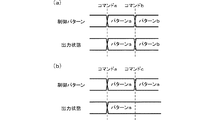
前記演出復帰判定手段が前記電力供給停止前の制御状態に復帰可能であると判定したときに、前記非復帰時制御情報(設定変更開始コマンド、RAM異常を示すエラーコマンド)または前記復帰時制御情報(復帰コマンド)を受信したか否かに関わらず、前記演出制御手段(サブ制御部91)の制御状態を前記演出バックアップデータ(RAM91cの格納データ)に基づいて電力供給停止前の制御状態に復帰させる演出復帰手段と、
前記非復帰時制御情報(設定変更開始コマンド、RAM異常を示すエラーコマンド)を受信したときに、前記演出制御手段(サブ制御部91)の制御状態を遊技非復帰時の制御状態(設定変更報知の制御パターン、RAM異常エラーを報知する制御パターン)とする遊技非復帰時制御手段と、
前記遊技機への電力供給が開始した後、前記非復帰時制御情報(設定変更開始コマンド、RAM異常を示すエラーコマンド)または前記復帰時制御情報(復帰コマンド)のいずれかを受信したときに、前記演出出力制御手段による前記演出制御手段(サブ制御部91)の制御状態に基づく前記演出装置(液晶表示器51等)の出力制御を開始させる演出出力制御開始手段と、
を含み、
前記制御状態更新手段は、前記遊技機への電力供給が開始した後、前記非復帰時制御情報(設定変更開始コマンド、RAM異常を示すエラーコマンド)または前記復帰時制御情報(復帰コマンド)のいずれかを受信する前に、該非復帰時制御情報(設定変更開始コマンド、RAM異常を示すエラーコマンド)及び該復帰時制御情報(復帰コマンド)以外の前記制御情報(コマンド)を受信したときでも、該受信した制御情報(コマンド)に基づいて前記演出制御手段(サブ制御部91)の制御状態を更新する
ことを特徴としている。
この特徴によれば、遊技制御手段が電力供給停止前の制御状態に復帰する場合に送信される復帰時制御情報を受信するまで、演出制御手段の制御状態に基づく演出装置の出力制御が開始しないため、遊技制御手段が故障して非復帰時制御情報を送信できない状況であっても、電力供給停止前の制御状態に基づいて演出装置の出力が復帰してしまうことがなく、このような状況であっても遊技制御手段の制御状態と演出装置による出力状態とを整合させることができる。
また、演出制御手段が、電力供給が開始した後、非復帰時制御情報または復帰時制御情報の受信前の状態であり、電力供給停止前の制御状態に基づいて演出装置の出力が復帰していない状態であっても、他の制御情報を受信した際に、受信した制御情報に基づいて演出制御手段の制御状態は更新され、復帰時制御情報を受信した後、更新された制御状態に基づいて演出装置の出力が開始するので、制御情報格納手段に未送信の制御情報が格納されたままの状態で復帰した場合でも、他の制御情報と同様に復帰時制御情報を生成し、制御情報格納手段に格納し、他の制御情報と同様の制御で生成された順番に復帰時制御情報を送信することで、演出制御手段の制御状態に未送信の制御情報を反映させることができる。
尚、前記遊技復帰判定手段が、前記遊技機への電力供給が開始したときに、前記遊技制御手段の制御状態を前記遊技バックアップデータに基づいて電力供給停止前の制御状態に復帰させるか否かを判定するとは、前記遊技バックアップデータから電力供給停止前の制御状態に復帰可能か否かを判定するものに限らず、初期化操作などによって意図的に電力供給停止前の制御状態に復帰させない制御を行うか否かを判定するものも含む。
また、前記演出制御手段は、前記演出装置の出力制御を直接行うものに限らず、例えば、遊技制御手段からの制御情報を受けて出力態様を決定する第1の演出制御手段と、前記演出装置の出力制御を直接的に行う第2の演出制御手段と、を別個に備える場合であれば、これら第1の演出制御手段及び第2の演出制御手段の双方を合わせて前記演出制御手段が構成されるものである。
In order to solve the above-described problem, a gaming machine according to
A gaming machine (slot machine 1) capable of performing a predetermined game,
A game control means (main control unit 41) for controlling the progress of the game and transmitting control information (command) based on the progress control of the game;
An effect device (such as the liquid crystal display 51) that performs an effect;
Effect control means (sub control unit 91) for performing output control by the effect device (
With
The game control means (main control unit 41)
Control information storage means (command transmission buffer) capable of storing a plurality of the control information (commands);
Control information generating means for generating control information (command) according to the progress control of the game, and storing it in the control information storage means (command transmission buffer);
Stopping power supply to the gaming machine, the power control state of the control information storing means and said game control means including a control information stored in the (command transmission buffer) (command) (main controller 41) Game backup data holding means for holding game backup data (stored data in the
When power supply to the gaming machine is started, the control state of the game control means (main control unit 41) is returned to the control state before the power supply is stopped based on the game backup data (stored data in the
When the game return determination means determines to return to the control state before the power supply stop, the control state of the game control means (main control unit 41) is based on the game backup data (stored data in the
When the game return determination means determines not to return to the control state before the power supply stop, non-return control information (setting change start command, error command indicating RAM abnormality) is generated, and the control information storage means ( Non-return-time control information generation means stored in the command transmission buffer),
Return-time control information generating means for generating return-time control information (return command) when the game return means returns to the control state before the power supply stop, and storing it in the control information storage means (command transmission buffer) When,
Control information transmission means for transmitting the control information (command) stored in the control information storage means (command transmission buffer) to the effect control means (sub-control unit 91) in the order of generation;
Including
The production control means (sub control unit 91)
Control state update means for updating the control state of the effect control means (sub control unit 91) based on reception of the control information (command);
Effect output control means for performing output control of the effect device (
Even if the power supply to the gaming machine is stopped, the effect backup data (stored data in the
When the power supply to the gaming machine is started, the control state of the effect control means (sub control unit 91) can be restored to the control state before the power supply is stopped based on the effect backup data (stored data in the
The non-return control information (setting change start command, error command indicating RAM abnormality) or the return control information when the effect return determination means determines that the control state before the power supply stop can be returned Regardless of whether or not (return command) is received, the control state of the effect control means (sub control unit 91) is returned to the control state before the stop of power supply based on the effect backup data (stored data in the
When the non-return control information (setting change start command, error command indicating RAM abnormality) is received, the control state of the effect control means (sub control unit 91) is changed to the control state (setting change notification) when the game is not returned. A non-returning-time control means, such as a control pattern of (2), a control pattern for informing a RAM abnormality error),
After power supply to the gaming machine is started, when either the non-return control information (setting change start command, error command indicating RAM abnormality) or the return control information (return command) is received, Effect output control starting means for starting output control of the effect device (
Including
After the power supply to the gaming machine is started, the control state update means is configured to either the non-return control information (setting change start command, error command indicating RAM abnormality) or the return control information (return command). Even when the control information (command) other than the non-return control information (setting change start command, error command indicating RAM abnormality) and the return control information (return command) is received before receiving The control state of the effect control means (sub control unit 91) is updated based on the received control information (command).
According to this feature, the output control of the effect device based on the control state of the effect control means does not start until the game control means receives the return control information transmitted when the game control means returns to the control state before stopping the power supply. Therefore, even in a situation where the game control means fails and the non-return-time control information cannot be transmitted, the output of the effect device does not return based on the control state before the power supply is stopped. Even so, the control state of the game control means and the output state of the effect device can be matched.
Further, after the power supply is started, the production control means is in a state before receiving the non-return control information or the return control information, and the output of the production device is restored based on the control state before the power supply is stopped. Even if there is no state, when other control information is received, the control state of the effect control means is updated based on the received control information, and after receiving the return time control information, based on the updated control state Since the output of the rendering device starts, even if the control information storage means returns with the untransmitted control information stored, the return control information is generated in the same manner as other control information, and the control information By storing the return time control information in the order generated by the same control as the other control information stored in the storage means, it is possible to reflect the untransmitted control information in the control state of the effect control means.
Whether or not the game return determination means returns the control state of the game control means to the control state before the power supply stop based on the game backup data when the power supply to the gaming machine is started. and determining, said not only from the gaming backup data that determines whether it is possible to return to the control state before the power outage and does not return to the control state before stopping intentionally powered by such initializing operation control It also includes those that determine whether or not to perform.
In addition, the effect control means is not limited to directly performing output control of the effect device, but, for example, a first effect control means that receives control information from a game control means and determines an output mode; and the effect device If the second production control means that directly controls the output control is separately provided, the production control means comprises both the first production control means and the second production control means. It is what is done.
本発明の手段1に記載の遊技機は、請求項1に記載の遊技機であって、
前記演出制御手段(サブ制御部91)は、前記演出復帰判定手段が前記電力供給停止前の制御状態に復帰可能でないと判定したときに、前記非復帰時制御情報(設定変更開始コマンド、RAM異常を示すエラーコマンド)または前記復帰時制御情報(復帰コマンド)を受信したか否かに関わらず、前記演出制御手段(サブ制御部91)の制御状態を初期化する制御状態初期化手段を含む
ことを特徴としている。
この特徴によれば、演出制御手段の制御状態が電力供給停止前の制御状態に復帰できない場合でも、遊技制御手段から復帰時制御情報を受信した際に、演出装置の出力が停止してしまうことがなく、初期化された制御状態に応じて演出装置の出力制御を開始することができる。
A gaming machine according to
The effect control means (sub-control unit 91) determines that the non-return control information (setting change start command, RAM abnormality) when the effect return determination means determines that it cannot return to the control state before stopping the power supply. Control state initialization means for initializing the control state of the effect control means (sub control unit 91) regardless of whether or not the return time control information (return command) is received. It is characterized by.
According to this feature, even when the control state of the effect control means cannot return to the control state before the power supply stop, when the return control information is received from the game control means, the output of the effect device stops. The output control of the rendering device can be started according to the initialized control state.
本発明の手段2に記載の遊技機は、請求項1または手段1に記載の遊技機であって、
前記演出出力制御手段は、前記遊技機への電力供給が開始した後、前記非復帰時制御情報(設定変更開始コマンド、RAM異常を示すエラーコマンド)または前記復帰時制御情報(復帰コマンド)のいずれかを受信するまでの期間において前記演出装置(液晶表示器51等)を所定の出力状態(復旧中パターンに応じた出力)に制御する
ことを特徴としている。
この特徴によれば、電力供給が開始された後、演出制御手段の制御状態に基づいて演出装置の出力が開始する前の状態でも、演出制御手段が現在どのような状態にあるか、を外部から容易に確認することができる。
The gaming machine according to
After the power supply to the gaming machine is started, the effect output control means is configured to output either the non-return control information (setting change start command, error command indicating RAM abnormality) or the return control information (return command). In the period until the message is received, the effect device (the
According to this feature, after the power supply is started, it is possible to determine in what state the effect control means is currently in the state before the output of the effect device starts based on the control state of the effect control means. Can be easily confirmed.
本発明の手段3に記載の遊技機は、請求項1、手段1または2のいずれかに記載の遊技機であって、
前記遊技制御手段(メイン制御部41)が搭載された遊技制御基板(遊技制御基板40)と、
前記演出制御手段(サブ制御部91)が搭載された演出制御基板(演出制御基板90)と、
を備え、
前記演出制御基板(演出制御基板90)の電力が遊技制御基板(遊技制御基板40)を介して供給されるとともに、前記演出制御基板(演出制御基板90)に対して前記制御情報(コマンド)を伝送する信号線(コマンド伝送ライン)と電力の供給線(電力供給ライン)とが1つのコネクタを介して前記演出制御基板(演出制御基板90)と接続される
ことを特徴としている。
この特徴によれば、遊技制御部から制御情報を伝送する信号線が演出制御部に接続されている状態でなければ、演出制御部に電力が供給されず、演出制御部のみが動作してしまうことがない。
A gaming machine according to means 3 of the present invention is the gaming machine according to
A game control board (game control board 40) on which the game control means (main control unit 41) is mounted;
An effect control board (effect control board 90) on which the effect control means (sub-control unit 91) is mounted;
With
The power of the effect control board (effect control board 90) is supplied via the game control board (game control board 40), and the control information (command) is sent to the effect control board (effect control board 90). A transmission signal line (command transmission line) and a power supply line ( power supply line) are connected to the effect control board (effect control board 90) through one connector.
According to this feature, unless the signal line for transmitting control information from the game control unit is connected to the effect control unit, power is not supplied to the effect control unit, and only the effect control unit operates. There is nothing.
本発明の手段4に記載の遊技機は、請求項1、手段1〜3のいずれかに記載の遊技機であって、
前記演出制御手段(サブ制御部91)は、前記遊技機への電力供給が開始した後、前記非復帰時制御情報(設定変更開始コマンド、RAM異常を示すエラーコマンド)または前記復帰時制御情報(復帰コマンド)のいずれも受信せずに所定時間(検査モード移行待ち時間)経過したときに、前記演出装置(液晶表示器51等)の検査を行うための検査状態(検査モード)に制御する検査制御手段を含む
ことを特徴としている。
この特徴によれば、遊技制御手段と接続せずに起動させるのみで検査制御状態に制御させることが可能となるため、遊技機の開発段階や製造段階において演出装置の検査を容易に行うことができる。
The gaming machine according to means 4 of the present invention is the gaming machine according to any one of
After the power supply to the gaming machine is started, the effect control means (sub control unit 91) is configured to perform the non-return control information (setting change start command, error command indicating RAM abnormality) or the return control information ( Inspection that controls to the inspection state (inspection mode) for inspecting the rendering device (
According to this feature, since it is possible to control the inspection control state only by starting without connecting to the game control means, it is possible to easily inspect the stage device at the development stage or manufacturing stage of the gaming machine. it can.
本発明の実施例を以下に説明する。 Examples of the present invention will be described below.
本発明が適用されたスロットマシンの実施例を図面を用いて説明すると、本実施例のスロットマシン1は、前面が開口する筐体1aと、この筐体1aの側端に回動自在に枢支された前面扉1bと、から構成されている。
An embodiment of a slot machine to which the present invention is applied will be described with reference to the drawings. A
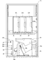
本実施例のスロットマシン1の筐体1aの内部には、図2に示すように、外周に複数種の図柄が配列されたリール2L、2C、2R(以下、左リール、中リール、右リール)が水平方向に並設されており、図1に示すように、これらリール2L、2C、2Rに配列された図柄のうち連続する3つの図柄が前面扉1bに設けられた透視窓3から見えるように配置されている。
Inside the
リール2L、2C、2Rの外周部には、図3に示すように、それぞれ「黒7」、「網7(図中網掛け7)」、「白7」、「BAR」、「リプレイ」、「スイカ」、「黒チェリー」、「白チェリー」、「ベル」、「オレンジ」といった互いに識別可能な複数種類の図柄が所定の順序で、それぞれ21個ずつ描かれている。リール2L、2C、2Rの外周部に描かれた図柄は、透視窓3において各々上中下三段に表示される。
As shown in FIG. 3, on the outer periphery of the
各リール2L、2C、2Rは、各々対応して設けられリールモータ32L、32C、32R(図4参照)によって回転させることで、各リール2L、2C、2Rの図柄が透視窓3に連続的に変化しつつ表示されるとともに、各リール2L、2C、2Rの回転を停止させることで、透視窓3に3つの連続する図柄が表示結果として導出表示されるようになっている。
The
リール2L、2C、2Rの内側には、リール2L、2C、2Rそれぞれに対して、基準位置を検出するリールセンサ33L、33C、33Rと、リール2L、2C、2Rを背面から照射するリールLED55と、が設けられている。また、リールLED55は、リール2L、2C、2Rの連続する3つの図柄に対応する12のLEDからなり、各図柄をそれぞれ独立して照射可能とされている。
Inside the
前面扉1bの各リール2L、2C、2Rの手前側(遊技者側)の位置には、液晶表示器51(図1参照)の表示領域51aが配置されている。液晶表示器51は、液晶素子に対して電圧が印加されていない状態で、透過性を有するノーマリーホワイトタイプの液晶パネルを有しており、表示領域51aの透視窓3に対応する透過領域51b及び透視窓3を介して遊技者側から各リール2L、2C、2Rが視認できるようになっている。また、表示領域51aの透過領域51bを除く領域の裏面には、背後から表示領域51aを照射するバックライト(図示略)が設けられているとともに、さらにその裏面には、内部を隠蔽する隠蔽部材(図示略)が設けられている。
A
液晶表示器51の前面側(図1においては手前側)には、表示面に対する遊技者からの指示(たとえば、タッチ操作)を検出し、当該位置(たとえば、タッチ操作された位置)を特定するためのタッチパネルを構成する発光装置56a、56bと、受光装置57a、57bと、が設置されている。発光装置56a、56bは、赤外線の発光素子(たとえば、LED)を複数備えている。受光装置57a、57bは、赤外線の受光素子(たとえば、フォトトランジスター)を複数備えている。
On the front side (front side in FIG. 1) of the
発光装置56aと受光装置57aとは、液晶表示器51の表示面を挟んで、水平方向に対に設置されている。発光装置56aと受光装置57aとは、発光装置56aが備える複数の発光素子から放射される赤外線を、受光装置57aが備える複数の受光素子により受光可能に設置されている。同様に、発光装置56bと受光装置57bとは、液晶表示器51の表示領域を挟んで、垂直方向に対に設置されている。発光装置56bと受光装置57bとは、発光装置56bが備える複数の発光素子から放射される赤外線を、受光装置57bが備える複数の受光素子により受光可能に設置されている。
The
本実施例では、発光装置56a、56bから赤外線を投射することにより、液晶表示器51の表示面に沿って赤外線のグリッドが形成される。そして、表示面に対して遊技者によりタッチ操作が行なわれると、受光装置57a、57bは、赤外線の遮光を検出し、この検出された受光素子が配置されている位置を特定するための信号を、後述するタッチパネルコントローラ99に出力する。タッチパネルコントローラ99は、受光装置57a、57bからの信号に基づき、液晶表示器51の表示面に対してタッチ操作された位置を特定することができるようになっており、これらによってタッチパネルが形成されている。
In the present embodiment, infrared grids are formed along the display surface of the
タッチパネルを構成する発光装置56a、56bは、液晶表示器51の表示面の左辺および下辺に設置され、受光装置57a、57bは、液晶表示器51の表示面の右辺および上辺に設置されている。タッチパネルは、発光装置56a、56bおよび受光装置57a、57bにより囲まれた領域内のタッチ操作を検出し、タッチ操作された位置を特定することができるようになっている。
The
前面扉1bには、メダルを投入可能なメダル投入部4、メダルが払い出されるメダル払出口9、クレジット(遊技者所有の遊技用価値として記憶されているメダル数)を用いてメダル1枚分の賭数を設定する際に操作される1枚BETスイッチ5、クレジットを用いて、その範囲内において遊技状態に応じて定められた規定数の賭数のうち最大の賭数(本実施例では遊技状態がRB(BB)の場合には2、通常遊技状態では3)を設定する際に操作されるMAXBETスイッチ6、クレジットとして記憶されているメダル及び賭数の設定に用いたメダルを精算する(クレジット及び賭数の設定に用いた分のメダルを返却させる)際に操作される精算スイッチ10、ゲームを開始する際に操作されるスタートスイッチ7、リール2L、2C、2Rの回転を各々停止する際に操作されるストップスイッチ8L、8C、8R、が遊技者により操作可能にそれぞれ設けられている。
On the
また、前面扉1bには、クレジットとして記憶されているメダル枚数が表示されるクレジット表示器11、後述するBB中のメダルの獲得枚数やエラー発生時にその内容を示すエラーコード等が表示される遊技補助表示器12、入賞の発生により払い出されたメダル枚数が表示されるペイアウト表示器13が設けられている。
The
また、前面扉1bには、賭数が1設定されている旨を点灯により報知する1BETLED14、賭数が2設定されている旨を点灯により報知する2BETLED15、賭数が3設定されている旨を点灯により報知する3BETLED16、メダルの投入が可能な状態を点灯により報知する投入要求LED17、スタートスイッチ7の操作によるゲームのスタート操作が有効である旨を点灯により報知するスタート有効LED18、ウェイト(前回のゲーム開始から一定期間経過していないためにリールの回転開始を待機している状態)中である旨を点灯により報知するウェイト中LED19、後述するリプレイゲーム中である旨を点灯により報知するリプレイ中LED20が設けられている。
Further, on the
MAXBETスイッチ6の内部には、1枚BETスイッチ5及びMAXBETスイッチ6の操作による賭数の設定操作が有効である旨を点灯により報知するBETスイッチ有効LED21(図4参照)が設けられており、ストップスイッチ8L、8C、8Rの内部には、該当するストップスイッチ8L、8C、8Rによるリールの停止操作が有効である旨を点灯により報知する左、中、右停止有効LED22L、22C、22R(図4参照)がそれぞれ設けられている。
Inside the
前面扉1bの内側には、所定のキー操作により後述するエラー状態及び後述する打止状態を解除するためのリセット操作を検出するリセットスイッチ23、後述する設定値の変更中や設定値の確認中にその時点の設定値が表示される設定値表示器24、メダル投入部4から投入されたメダルの流路を、筐体1a内部に設けられた後述のホッパータンク34a(図2参照)側またはメダル払出口9側のいずれか一方に選択的に切り替えるための流路切替ソレノイド30、メダル投入部4から投入され、ホッパータンク34a側に流下したメダルを検出する投入メダルセンサ31を有するメダルセレクタ(図示略)、前面扉1bの開放状態を検出するドア開放検出スイッチ25(図4参照)が設けられている。
Inside the
筐体1a内部には、図2に示すように、前述したリール2L、2C、2R、リールモータ32L、32C、32R、各リール2L、2C、2Rのリール基準位置をそれぞれ検出可能なリールセンサ33L、33C、33R(図4参照)からなるリールユニット2、外部出力信号を出力するための外部出力基板1000、メダル投入部4から投入されたメダルを貯留するホッパータンク34a、ホッパータンク34aに貯留されたメダルをメダル払出口9より払い出すためのホッパーモータ34b、ホッパーモータ34bの駆動により払い出されたメダルを検出する払出センサ34cからなるホッパーユニット34、電源ボックス100が設けられている。
As shown in FIG. 2, a
ホッパーユニット34の側部には、ホッパータンク34aから溢れたメダルが貯留されるオーバーフロータンク35が設けられている。オーバーフロータンク35の内部には、貯留された所定量のメダルを検出可能な高さに設けられた左右に離間する一対の導電部材からなる満タンセンサ35aが設けられており、導電部材がオーバーフロータンク35内に貯留されたメダルを介して接触することにより導電したときに内部に貯留されたメダル貯留量が所定量以上となったこと、すなわちオーバーフロータンクが満タン状態となったことを検出できるようになっている。
On the side of the
電源ボックス100の前面には、後述のBB終了時に打止状態(リセット操作がなされるまでゲームの進行が規制される状態)に制御する打止機能の有効/無効を選択するための打止スイッチ36a、後述のBB終了時に自動精算処理(クレジットとして記憶されているメダルを遊技者の操作によらず精算(返却)する処理)に制御する自動精算機能の有効/無効を選択するための自動精算スイッチ36b、起動時に設定変更モードに切り替えるための設定キースイッチ37、通常時においてはエラー状態や打止状態を解除するためのリセットスイッチとして機能し、設定変更モードにおいては後述する内部抽選の当選確率(出玉率)の設定値を変更するための設定スイッチとして機能するリセット/設定スイッチ38、電源をON/OFFする際に操作される電源スイッチ39が設けられている。
On the front surface of the
本実施例のスロットマシン1においてゲームを行う場合には、まず、メダルをメダル投入部4から投入するか、あるいはクレジットを使用して賭数を設定する。クレジットを使用するには1枚BETスイッチ5またはMAXBETスイッチ6を操作すれば良い。遊技状態に応じて定められた規定数の賭数が設定されると、入賞ラインL1〜L5(図1参照)が有効となり、スタートスイッチ7の操作が有効な状態、すなわち、ゲームが開始可能な状態となる。本実施例では、規定数の賭数として遊技状態がRB(BB)では2枚、通常遊技状態では3枚が定められている。尚、遊技状態に対応する規定数のうち最大数を超えてメダルが投入された場合には、その分はクレジットに加算される。
When a game is played in the
入賞ラインとは、各リール2L、2C、2Rの透視窓3に表示された図柄の組合せが入賞図柄の組合せであるかを判定するために設定されるラインである。本実施例では、図1に示すように、各リール2L、2C、2Rの中段に並んだ図柄に跨って設定された入賞ラインL1、各リール2L、2C、2Rの上段に並んだ図柄に跨って設定された入賞ラインL2、各リール2L、2C、2Rの下段に並んだ図柄に跨って設定された入賞ラインL3、リール2Lの上段、リール2Cの中段、リール2Rの下段、すなわち右下がりに並んだ図柄に跨って設定された入賞ラインL4、リール2Lの下段、リール2Cの中段、リール2Rの上段、すなわち右上がりに並んだ図柄に跨って設定された入賞ラインL5の5種類が入賞ラインとして定められている。
The winning line is a line that is set to determine whether a combination of symbols displayed on the
ゲームが開始可能な状態でスタートスイッチ7を操作すると、各リール2L、2C、2Rが回転し、各リール2L、2C、2Rの図柄が連続的に変動する。この状態でいずれかのストップスイッチ8L、8C、8Rを操作すると、対応するリール2L、2C、2Rの回転が停止し、透視窓3に表示結果が導出表示される。
When the
そして全てのリール2L、2C、2Rが停止されることで1ゲームが終了し、有効化されたいずれかの入賞ラインL1〜L5上に予め定められた図柄の組合せ(以下、役とも呼ぶ)が各リール2L、2C、2Rの表示結果として停止した場合には入賞が発生し、その入賞に応じて定められた枚数のメダルが遊技者に対して付与され、クレジットに加算される。また、クレジットが上限数(本実施例では50)に達した場合には、メダルが直接メダル払出口9(図1参照)から払い出されるようになっている。尚、有効化された複数の入賞ライン上にメダルの払出を伴う図柄の組合せが揃った場合には、有効化された入賞ラインに揃った図柄の組合せそれぞれに対して定められた払出枚数を合計し、合計した枚数のメダルが遊技者に対して付与されることとなる。ただし、1ゲームで付与されるメダルの払出枚数には、上限(本実施例では15枚)が定められており、合計した払出枚数が上限を超える場合には、上限枚数のメダルが付与されることとなる。また、有効化されたいずれかの入賞ラインL1〜L5上に、遊技状態の移行を伴う図柄の組合せが各リール2L、2C、2Rの表示結果として停止した場合には図柄の組合せに応じた遊技状態に移行するようになっている。
When one of the
図4は、スロットマシン1の構成を示すブロック図である。スロットマシン1には、図4に示すように、遊技制御基板40、演出制御基板90、電源基板101が設けられており、遊技制御基板40によって遊技状態が制御され、演出制御基板90によって遊技状態に応じた演出が制御され、電源基板101によってスロットマシン1を構成する電気部品の駆動電源が生成され、各部に供給される。
FIG. 4 is a block diagram showing a configuration of the
電源基板101には、外部からAC100Vの電源が供給されるとともに、このAC100Vの電源からスロットマシン1を構成する電気部品の駆動に必要な直流電圧が生成され、遊技制御基板40及び遊技制御基板40を介して接続された演出制御基板90に供給されるようになっている。
The
また、電源基板101には、前述したホッパーモータ34b、払出センサ34c、満タンセンサ35a、打止スイッチ36a、自動精算スイッチ36b、設定キースイッチ37、リセット/設定スイッチ38、電源スイッチ39が接続されている。
Further, the above-described
遊技制御基板40には、前述した1枚BETスイッチ5、MAXBETスイッチ6、スタートスイッチ7、ストップスイッチ8L、8C、8R、精算スイッチ10、リセットスイッチ23、投入メダルセンサ31、ドア開放検出スイッチ25、リールセンサ33L、33C、33Rが接続されているとともに、電源基板101を介して前述した払出センサ34c、満タンセンサ35a、打止スイッチ36a、自動精算スイッチ36b、設定キースイッチ37、リセット/設定スイッチ38が接続されており、これら接続されたスイッチ類の検出信号が入力されるようになっている。
On the
また、遊技制御基板40には、前述したクレジット表示器11、遊技補助表示器12、ペイアウト表示器13、1〜3BETLED14〜16、投入要求LED17、スタート有効LED18、ウェイト中LED19、リプレイ中LED20、BETスイッチ有効LED21、左、中、右停止有効LED22L、22C、22R、設定値表示器24、流路切替ソレノイド30、リールモータ32L、32C、32Rが接続されているとともに、電源基板101を介して前述したホッパーモータ34bが接続されており、これら電気部品は、遊技制御基板40に搭載された後述のメイン制御部41の制御に基づいて駆動されるようになっている。
Further, the
遊技制御基板40には、メインCPU41a、ROM41b、RAM41c、I/Oポート41dを備えたマイクロコンピュータからなり、遊技の制御を行うメイン制御部41、所定範囲(本実施例では0〜65535)の乱数を発生させる乱数発生回路42、乱数発生回路から乱数を取得するサンプリング回路43、遊技制御基板40に直接または電源基板101を介して接続されたスイッチ類から入力された検出信号を検出するスイッチ検出回路44、リールモータ32L、32C、32Rの駆動制御を行うモータ駆動回路45、流路切替ソレノイド30の駆動制御を行うソレノイド駆動回路46、遊技制御基板40に接続された各種表示器やLEDの駆動制御を行うLED駆動回路47、スロットマシン1に供給される電源電圧を監視し、電圧低下を検出したときに、その旨を示す電圧低下信号をメイン制御部41に対して出力する電断検出回路48、電源投入時またはメインCPU41aからの初期化命令が入力されないときにメインCPU41aにリセット信号を与えるリセット回路49、その他各種デバイス、回路が搭載されている。
The
メインCPU41aは、計時機能、タイマ割込などの割込機能(割込禁止機能を含む)を備え、ROM41bに記憶されたプログラム(後述)を実行して、遊技の進行に関する処理を行うととともに、遊技制御基板40に搭載された制御回路の各部を直接的または間接的に制御する。ROM41bは、メインCPU41aが実行するプログラムや各種テーブル等の固定的なデータを記憶する。RAM41cは、メインCPU41aがプログラムを実行する際のワーク領域等として使用される。I/Oポート41dは、メイン制御部41が備える信号入出力端子を介して接続された各回路との間で制御信号を入出力する。
The
メイン制御部41は、信号入力端子を備えており、遊技制御基板40に接続された各種スイッチ類の検出状態がこれら信号入力端子を介して入力ポートに入力される。これら信号入力端子の入力状態は、メインCPU41aにより監視されており、メインCPU41aは、信号入力端子の入力状態、すなわち各種スイッチ類の検出状態に応じて段階的に移行する基本処理を実行する。
The
また、メインCPU41aは、前述のように割込機能を備えており、割込の発生により基本処理に割り込んで割込処理を実行できるようになっている。本実施例では、割込1〜4の4種類の割込を実行可能であり、各割込毎にカウンタモード(信号入力端子とは別個に設けられたトリガー端子からの信号入力に応じて外部割込を発生させる割込モード)とタイマモード(メインCPU41aのクロック入力数に応じて内部割込を発生させる割込モード)のいずれかを選択して設定できるようになっている。
Further, the
本実施例では、割込1〜4のうち、割込2がカウンタモードに設定され、割込3がタイマモードに設定され、割込1、4は未使用とされている。トリガー端子は、前述した電断検出回路48と接続されており、メインCPU41aは電断検出回路48から出力された電圧低下信号の入力に応じて割込2を発生させて後述する電断割込処理(メイン)を実行する。また、メインCPU41aは、クロック入力数が一定数に到達する毎、すなわち一定時間間隔(本実施例では、約0.56ms)毎に割込3を発生させて後述するタイマ割込処理(メイン)を実行する。また、割込1、4は、未使用に設定されているが、ノイズ等によって割込1、4が発生することがあり得る。このため、メインCPU41aは、割込1、4が発生した場合に、もとの処理に即時復帰させる未使用割込処理を実行するようになっている。
In the present embodiment, among the interrupts 1 to 4, interrupt 2 is set to the counter mode, interrupt 3 is set to the timer mode, and interrupts 1 and 4 are unused. The trigger terminal is connected to the power
また、メインCPU41aは、割込1〜4のいずれかの割込の発生に基づく割込処理の実行中に他の割込を禁止するように設定されているとともに、複数の割込が同時に発生した場合には、割込2、3、1、4の順番で優先して実行する割込が設定されている。すなわち割込2とその他の割込が同時に発生した場合には、割込2を優先して実行し、割込3と割込1または4が同時に発生した場合には、割込3を優先して実行するようになっている。
The
また、メインCPU41aは、割込1〜4のいずれかの割込の発生に基づく割込処理の開始時に、レジスタに格納されている使用中のデータをRAM41cに設けられた後述のスタック領域に一時的に退避させるとともに、当該割込処理の終了時にスタック領域に退避させたデータをレジスタに復帰させるようになっている。
Further, the
また、メイン制御部41には、停電時においてもバックアップ電源が供給されており、バックアップ電源が供給されている間は、RAM41cに記憶されているデータが保持されるようになっている。
Further, the
メインCPU41aは、基本処理として遊技制御基板40に接続された各種スイッチ類の検出状態が変化するまでは制御状態に応じた処理を繰り返しループし、各種スイッチ類の検出状態の変化に応じて段階的に移行する処理を実行する。また、メインCPU41aは、前述のように割込機能を備えており、割込の発生により基本処理に割り込んで割込処理を実行できるようになっており、電断検出回路48から出力された電圧低下信号の入力に応じて電断割込処理(メイン)を実行し、一定時間間隔(本実施例では、約0.56ms)毎にタイマ割込処理(メイン)を実行する。尚、タイマ割込処理(メイン)の実行間隔は、基本処理において制御状態に応じて繰り返す処理が一巡する時間とタイマ割込処理(メイン)の実行時間とを合わせた時間よりも長い時間に設定されており、今回と次回のタイマ割込処理(メイン)との間で必ず制御状態に応じて繰り返す処理が最低でも一巡することとなる。
The
メインCPU41aは、I/Oポート41dを介して演出制御基板90に、各種のコマンドを送信する。遊技制御基板40から演出制御基板90へ送信されるコマンドは一方向のみで送られ、演出制御基板90から遊技制御基板40へ向けてコマンドが送られることはない。遊技制御基板40から演出制御基板90へ送信されるコマンドの伝送ラインは、ストローブ(INT)信号ライン、データ伝送ライン、グラウンドラインから構成されているとともに、演出中継基板80を介して接続されており、遊技制御基板40と演出制御基板90とが直接接続されない構成とされている。
The
図5に示すように、メインCPU41aが搭載された遊技制御基板40と演出制御基板90とは演出中継基板80を介して接続されている。遊技制御基板40と演出中継基板80とはゲーブルC1を介して接続され、演出中継基板80と演出制御基板90とはケーブルC2を介して接続されている。遊技制御基板40とケーブルC1とは遊技制御基板40に実装されたコネクタ40aとケーブルC1の一端に設けられたコネクタC1aとを連結することで接続される。ケーブルC1と演出中継基板80とはケーブルC1の他端に設けられたコネクタC1bと演出中継基板80に実装されたコネクタ80aとを連結することで接続される。演出中継基板80とケーブルC2とは演出中継基板80に実装されたコネクタ80bとケーブルC1の一端に設けられたコネクタC2aとを連結することで接続される。ケーブルC2と演出制御基板90とはケーブルC2の他端に設けられたコネクタC2bと演出制御基板90に実装されたコネクタ90aとを連結することで接続される。
As shown in FIG. 5, the
また、図5に示すように、メインCPU41aからのコマンド伝送ラインを構成するストローブ信号ライン(INT)、データ伝送ライン(D1〜D8)、グラウンドライン(GRD)と、遊技制御基板40から演出制御基板90に対して電源を供給するDC12Vラインと、が一系統のケーブルC1及びC2及びコネクタを介して接続されており、これらケーブルと各基板とを接続するコネクタ同士が全て接続されることで演出制御基板90側の各部が動作可能となり、かつメインCPU41aからのコマンドを受信可能な状態となる。このため、メインCPU41aからコマンドを伝送するコマンド伝送ラインが演出制御基板90に接続されている状態でなければ、演出制御基板90側に電源が供給されず、演出制御基板90側のみが動作してしまうことがない。
Further, as shown in FIG. 5, a strobe signal line (INT), a data transmission line (D1 to D8), a ground line (GRD) constituting a command transmission line from the
演出制御基板90には、前述したタッチパネルを構成する受光装置57a、57bが接続されており、これら接続された受光装置57a、57bの検出信号がタッチパネルコントローラ99に入力されるようになっている。
The
演出制御基板90には、スロットマシン1の前面扉1bに配置された液晶表示器51(図1参照)、演出効果LED52、スピーカ53、54、前述したリールLED55等の演出装置が接続されており、これら演出装置は、演出制御基板90に搭載された後述のサブ制御部91による制御に基づいて駆動されるようになっている。また、演出制御基板90には、前述したタッチパネルを構成する発光装置56a、56bが接続されており、発光装置56a、56bは、演出制御基板90に搭載された後述のタッチパネルコントローラ99による制御に基づいて駆動されるようになっている。
The
尚、本実施例では、演出制御基板90に搭載されたサブ制御部91により、液晶表示器51、演出効果LED52、スピーカ53、54、リールLED55等の演出装置の出力制御が行われる構成であるが、サブ制御部91とは別に演出装置の出力制御を直接的に行う出力制御部を演出制御基板90または他の基板に搭載し、サブ制御部91がメイン制御部41からのコマンドに基づいて演出装置の出力パターンを決定し、サブ制御部91が決定した出力パターンに基づいて出力制御部が演出装置の出力制御を行う構成としても良く、このような構成では、サブ制御部91及び出力制御部の双方によって演出装置の出力制御が行われることとなる。
In this embodiment, the
また、本実施例では、演出装置として液晶表示器51、演出効果LED52、スピーカ53、54、リールLED55を例示しているが、演出装置は、これらに限られず、例えば、機械的に駆動する表示装置や機械的に駆動する役モノなどを演出装置として適用しても良い。
Further, in the present embodiment, the
演出制御基板90には、メイン制御部41と同様にサブCPU91a、ROM91b、RAM91c、I/Oポート91dを備えたマイクロコンピュータにて構成され、演出の制御を行うサブ制御部91、演出制御基板90に接続された液晶表示器51の表示制御を行う表示制御回路92、演出効果LED52、リールLED55の駆動制御を行うLED駆動回路93、スピーカ53、54からの音声出力制御を行う音声出力回路94、電源投入時またはサブCPU91aからの初期化命令が一定時間入力されないときにサブCPU91aにリセット信号を与えるリセット回路95、日付情報及び時刻情報を含む時間情報を出力する時計装置97、スロットマシン1に供給される電源電圧を監視し、電圧低下を検出したときに、その旨を示す電圧低下信号をサブCPU91aに対して出力する電断検出回路98、受光装置57a、57bからの信号に基づき、液晶表示器51の表示面に対してタッチ操作された位置を特定する処理などを行うタッチパネルコントローラ99、その他の回路等、が搭載されており、サブCPU91aは、遊技制御基板40から送信されるコマンド、タッチパネルコントローラ99からの出力情報を受けて、演出を行うための各種の制御を行うとともに、演出制御基板90に搭載された制御回路の各部を直接的または間接的に制御する。
Similar to the
サブCPU91aは、メインCPU41aと同様に、割込機能(割込禁止機能を含む)を備える。サブ制御部91の割込端子の1つは、コマンド伝送ラインのうち、メイン制御部41がコマンドを送信する際に出力するストローブ(INT)信号線に接続されており、サブCPU91aは、ストローブ信号の入力に基づいて割込を発生させて、メイン制御部41からのコマンドを取得し、バッファに格納するコマンド受信割込処理を実行する。また、サブCPU91aは、クロック入力数が一定数に到達する毎、すなわち一定間隔毎に割込を発生させて後述するタイマ割込処理(サブ)を実行する。また、サブ制御部91の割込端子の1つは、電断検出回路98と接続されており、サブCPU91aは、電断検出回路98から出力された電圧低下信号の入力に応じて電断割込処理(サブ)を実行する。また、サブCPU91aにおいても未使用の割込が発生した場合には、もとの処理に即時復帰させる未使用割込処理を実行するようになっている。
Similar to the
また、サブCPU91aは、メインCPU41aとは異なり、ストローブ信号(INT)の入力に基づいて割込が発生した場合には、タイマ割込処理(サブ)の実行中であっても、当該処理に割り込んでコマンド受信割込処理を実行し、タイマ割込処理(サブ)の契機となる割込が同時に発生してもコマンド受信割込処理を最優先で実行するようになっている。尚、電断割込処理(サブ)の実行中には、コマンド受信割込処理も禁止されるが、電断割込処理(サブ)の契機となる割込が同時に発生した場合にはコマンド受信割込処理を優先して実行する
Also, unlike the
また、サブ制御部91にも、停電時においてバックアップ電源が供給されており、バックアップ電源が供給されている間は、RAM91cに記憶されているデータが保持されるようになっている。
The
本実施例のスロットマシン1は、設定値に応じてメダルの払出率が変わるものである。詳しくは、後述する内部抽選において設定値に応じた当選確率を用いることにより、メダルの払出率が変わるようになっている。設定値は1〜6の6段階からなり、6が最も払出率が高く、5、4、3、2、1の順に払出率が低くなる。すなわち設定値として6が設定されている場合には、遊技者にとって最も有利度が高く、5、4、3、2、1の順に有利度が段階的に低くなる。
In the
設定値を変更するためには、設定キースイッチ37をON状態としてからスロットマシン1の電源をONする必要がある。設定キースイッチ37をON状態として電源をONすると、設定値表示器24にRAM41cから読み出された設定値が表示値として表示され、リセット/設定スイッチ38の操作による設定値の変更操作が可能な設定変更モードに移行する。設定変更モードにおいて、リセット/設定スイッチ38が操作されると、設定値表示器24に表示された表示値が1ずつ更新されていく(設定6からさらに操作されたときは、設定1に戻る)。そして、スタートスイッチ7が操作されると表示値が確定する。そして、設定キースイッチ37がOFFされると、確定した表示値が設定値としてメイン制御部41のRAM41cに格納され、遊技の進行が可能な状態に移行する。
In order to change the setting value, it is necessary to turn on the power of the
本実施例のスロットマシン1においては、メインCPU41aが電断検出回路48からの電圧低下信号を検出した際に、電断割込処理(メイン)を実行する。電断割込処理(メイン)では、レジスタを後述するRAM41cのスタックに退避し、RAM41cにいずれかのビットが1となる破壊診断用データ(本実施例では、5AH)、すなわち0以外の特定のデータを格納するとともに、RAM41cの全ての領域に格納されたデータに基づくRAMパリティが0となるようにRAMパリティ調整用データを計算し、RAM41cに格納する処理を行うようになっている。尚、RAMパリティとはRAM41cの該当する領域(本実施例では、全ての領域)の各ビットに格納されている値の排他的論理和として算出される値である。このため、RAM41cの全ての領域に格納されたデータに基づくRAMパリティが0であれば、RAMパリティ調整用データは0となり、RAM41cの全ての領域に格納されたデータに基づくRAMパリティが1であれば、RAMパリティ調整用データは1となる。
In the
そして、メインCPU41aは、その起動時においてRAM41cの全ての領域に格納されたデータに基づいてRAMパリティを計算するとともに、破壊診断用データの値を確認し、RAMパリティが0であり、かつ破壊診断用データの値も正しいことを条件に、RAM41cに記憶されているデータに基づいてメインCPU41aの処理状態を電断前の状態に復帰させるが、RAMパリティが0でない場合(1の場合)や破壊診断用データの値が正しくない場合には、RAM異常と判定し、RAM異常エラーコードをレジスタにセットしてRAM異常エラー状態に制御し、遊技の進行を不能化させるようになっている。尚、RAM異常エラー状態は、他のエラー状態と異なり、リセットスイッチ23やリセット/設定スイッチ38を操作しても解除されないようになっており、前述した設定変更モードにおいて新たな設定値が設定されるまで解除されることがない。
The
また、サブCPU91aも電断検出回路98からの電圧低下信号を検出した際に、電断割込処理(サブ)を実行する。電断割込処理(サブ)では、レジスタを後述するRAM91cのスタックに退避し、RAM91cにいずれかのビットが1となる破壊診断用データを格納するとともに、RAM91cの全ての領域に格納されたデータに基づくRAMパリティが0となるようにRAMパリティ調整用データを計算し、RAM91cに格納する処理を行うようになっている。
In addition, when the
そして、サブCPU91aは、その起動時においてRAM91cの全ての領域に格納されたデータに基づいてRAMパリティを計算し、RAMパリティが0であることを条件に、RAM91cに記憶されているデータに基づいてサブCPU91aの処理状態を電断前の状態に復帰させるが、RAMパリティが0でない場合(1の場合)には、RAM異常と判定し、RAM91cを初期化するようになっている。この場合、メインサブCPU91aと異なり、RAM91cが初期化されるのみで演出の実行が不能化されることはない。
Then, the
次に、メイン制御部41のRAM41cの初期化について説明する。メイン制御部41のRAM41cの格納領域は、重要ワーク、一般ワーク、特別ワーク、設定値ワーク、非保存ワーク、未使用領域、スタック領域に区分されている。
Next, initialization of the
重要ワークは、各種表示器やLEDの表示用データ、I/Oポート41dの入出力データ、遊技時間の計時カウンタ等、BB終了時に初期化すると不都合があるデータが格納されるワークである。一般ワークは、停止制御テーブル、停止図柄、メダルの払出枚数、BB中のメダル払出総数等、BB終了時に初期化可能なデータが格納されるワークである。特別ワークは、演出制御基板90へコマンドを送信するためのデータ、各種ソフトウェア乱数等、設定開始前にのみ初期化されるデータが格納されるワークである。設定値ワークは、内部抽選処理で抽選を行う際に用いる設定値が格納されるワークである。非保存ワークは、各種スイッチ類の状態を保持するワークであり、起動時にRAM41cのデータが破壊されているか否かに関わらず必ず値が設定されることとなる。未使用領域は、RAM41cの格納領域のうち使用していない領域であり、後述する複数の初期化条件のいずれか1つでも成立すれば初期化されることとなる。スタック領域は、メインCPU41aのレジスタから退避したデータが格納される領域であり、このうちの未使用スタック領域は、未使用領域と同様に、後述する複数の初期化条件のいずれか1つでも成立すれば初期化されることとなるが、使用中スタック領域は、プログラムの続行のため、初期化されることはない。
The important work is a work in which data that is inconvenient to be initialized at the end of the BB, such as various display devices and LED display data, input / output data of the I /
本実施例においてメインCPU41aは、設定キースイッチ37がONの状態での起動時、RAM異常エラー発生時、BB終了時、設定キースイッチ37がOFFの状態での起動時においてRAM41cのデータが破壊されていないとき、1ゲーム終了時の5つからなる初期化条件が成立した際に、各初期化条件に応じて初期化される領域の異なる4種類の初期化を行う。
In this embodiment, the
初期化1は、起動時において設定キースイッチ37がONの状態であり、設定変更モードへ移行する場合において、その前に行う初期化、またはRAM異常エラー発生時に行う初期化であり、初期化1では、RAM41cの格納領域のうち、使用中スタック領域を除く全ての領域(未使用領域及び未使用スタック領域を含む)が初期化される。初期化2は、BB終了時に行う初期化であり、初期化2では、RAM41cの格納領域のうち、一般ワーク、未使用領域及び未使用スタック領域が初期化される。初期化3は、起動時において設定キースイッチ37がOFFの状態であり、かつRAM41cのデータが破壊されていない場合において行う初期化であり、初期化3では、非保存ワーク、未使用領域及び未使用スタック領域が初期化される。初期化4は、1ゲーム終了時に行う初期化であり、初期化4では、RAM41cの格納領域のうち、未使用領域及び未使用スタック領域が初期化される。
尚、本実施例では、初期化1を設定変更モードの移行前に行っているが、設定変更モードの終了時に行ったり、設定変更モード移行前、設定変更モード終了時の双方で行うようにしても良い。この場合、設定値ワークを初期化してしまうと確定した設定値が失われてしまうこととなるので、設定変更モード終了時の初期化では、設定値ワークの初期化は行われない。
In this embodiment, the
本実施例のスロットマシン1は、前述のように遊技状態に応じて設定可能な賭数の規定数が定められており、遊技状態に応じて定められた規定数の賭数が設定されたことを条件にゲームを開始させることが可能となる。本実施例では、後に説明するが、遊技状態として、レギュラーボーナス(以下ではRBと称す)(ビッグボーナス(以下ではBBと称す))、通常遊技状態があり、このうちRB(BB)では賭数の規定数として2が定められており、通常遊技状態では賭数の規定数として3が定められている。このため、遊技状態がRB(BB)であれば、賭数として2が設定されるとゲームを開始させることが可能となり、通常遊技状態であれば、賭数として3が設定されるとゲームを開始させることが可能となる。尚、本実施例では、遊技状態に応じた規定数の賭数が設定された時点で、全ての入賞ラインL1〜L5が有効化されるようになっており、RB(BB)では賭数として2が定められた時点で全ての入賞ラインL1〜L5が有効化されることなり、通常遊技状態では賭数として3が設定された時点で全ての入賞ラインL1〜L5が有効化されることとなる。
In the
本実施例のスロットマシン1は、全てのリール2L、2C、2Rが停止した際に、有効化された入賞ライン(本実施例の場合、常に全ての入賞ラインが有効化されるため、以下では、有効化された入賞ラインを単に入賞ラインと呼ぶ)上に役と呼ばれる図柄の組合せが揃うと入賞となる。役は、同一図柄の組合せであっても良いし、異なる図柄を含む組合せであっても良い。入賞となる役の種類は、遊技状態に応じて定められているが、大きく分けて、メダルの払い出しを伴う小役と、賭数の設定を必要とせずに次のゲームを開始可能となる再遊技役と、遊技状態の移行を伴う特別役と、がある。以下では、小役と再遊技役をまとめて一般役とも呼ぶ。遊技状態に応じて定められた各役の入賞が発生するためには、後述する内部抽選に当選して、当該役の当選フラグがRAM41cに設定されている必要がある。
In the
尚、これら各役の当選フラグのうち、小役及び再遊技役の当選フラグは、当該フラグが設定されたゲームにおいてのみ有効とされ、次のゲームでは無効となるが、特別役の当選フラグは、当該フラグにより許容された役の組合せが揃うまで有効とされ、許容された役の組合せが揃ったゲームにおいて無効となる。すなわち特別役の当選フラグが一度当選すると、例え、当該フラグにより許容された役の組合せを揃えることができなかった場合にも、その当選フラグは無効とされずに、次のゲームへ持ち越されることとなる。 Of the winning flags for each of these combinations, the winning flag for the small role and the re-playing role is valid only in the game in which the flag is set, and is invalid in the next game. It is valid until a combination of combinations permitted by the flag is completed, and is invalid in a game having a combination of combinations permitted. In other words, once the special combination winning flag is won, even if the combination of the combinations permitted by the flag cannot be made, the winning flag is not invalidated and is carried over to the next game. It becomes.
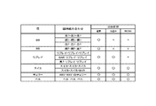
このスロットマシン1における役としては、図6に示すように、特別役としてビッグボーナス(以下ではビッグボーナスをBBとする)、レギュラーボーナス(以下ではレギュラーボーナスをRBとする)が、小役として1枚、スイカ、チェリー、ベルが、再遊技役としてリプレイ(1)〜(3)が定められている。
As shown in FIG. 6, the
チェリーは、いずれの遊技状態においても右リールについて入賞ラインのいずれかに「白チェリー」の図柄が導出されたときに入賞となり、いずれの遊技状態においても1枚のメダルが払い出される。尚、「白チェリー」の図柄が右リールの上段または下段に停止した場合には、入賞ラインL2、L5または入賞ラインL3、L4の2本の入賞ラインにチェリーの組合せが揃うこととなり、2本の入賞ライン上でチェリーに入賞したこととなるので、2枚のメダルが払い出されることとなる。 Cherry is awarded when the symbol “white cherry” is derived on any of the winning lines for the right reel in any gaming state, and one medal is paid out in any gaming state. In addition, when the symbol of “white cherry” stops at the upper or lower stage of the right reel, the combination of cherries is aligned on the two winning lines of the winning lines L2, L5 or the winning lines L3, L4. Since winning a cherry on the winning line, two medals will be paid out.
スイカは、いずれの遊技状態においても入賞ラインのいずれかに「スイカ−スイカ−スイカ」の組合せまたは「スイカ−スイカ−BAR」の組合せが揃ったときに入賞となり、RB(BB)では15枚のメダルが払い出され、通常遊技状態では12枚のメダルが払い出される。ベルは、いずれの遊技状態においても入賞ラインのいずれかに「ベル−ベル−ベル」の組合せが揃ったときに入賞となり、RB(BB)では15枚のメダルが払い出され、通常遊技状態では10枚のメダルが払い出される。 A watermelon is awarded when a combination of “watermelon-watermelon-watermelon” or “watermelon-watermelon-BAR” is available on any of the winning lines in any gaming state, and 15 RBs (BB). Medals are paid out, and in the normal gaming state, 12 medals are paid out. Bell is awarded when the combination of “Bell-Bell-Bell” is aligned on any of the winning lines in any gaming state, and 15 medals are paid out in RB (BB). Ten medals are paid out.
リプレイ(1)は、通常遊技状態において入賞ラインのいずれかに「リプレイ−リプレイ−リプレイ」の組合せ、「BAR−リプレイ−リプレイ」の組合せ、または「黒7−リプレイ−リプレイ」の組合せのうちいずれかの組合せが揃ったときに入賞となる。リプレイ(2)は、通常遊技状態において入賞ラインのいずれかに「スイカ−リプレイ−リプレイ」の組合せが揃ったときに入賞となる。リプレイ(3)は、通常遊技状態において入賞ラインのいずれかに「黒チェリー−リプレイ−リプレイ」の組合せが揃ったときに入賞となる。リプレイ(1)〜(3)が入賞したときには、メダルの払い出しはないが次のゲームを改めて賭数を設定することなく開始できるので、次のゲームで設定不要となった賭数に対応した3枚のメダルが払い出されるのと実質的には同じこととなる。 Replay (1) is a combination of “Replay-Replay-Replay”, “BAR-Replay-Replay”, or “Black 7-Replay-Replay” in any of the winning lines in the normal gaming state. A winning combination will be awarded when these combinations are available. Replay (2) is awarded when a combination of “watermelon-replay-replay” is arranged on any of the winning lines in the normal gaming state. Replay (3) is awarded when a combination of “black cherry-replay-replay” is arranged on any of the winning lines in the normal gaming state. When replays (1) to (3) win, there is no payout of medals, but the next game can be started again without setting the number of bets, so 3 corresponding to the number of bets that need not be set in the next game. This is essentially the same as a medal being paid out.
RBは、通常遊技状態において入賞ラインのいずれかに「網7−網7−黒7」の組合せが揃ったときに入賞となり、遊技状態がRBに移行する。RBは、小役、特にベルの当選確率が高まることによって他の遊技状態よりも遊技者にとって有利となる遊技状態であり、RBが開始した後、12ゲームを消化したとき、または8ゲーム入賞(役の種類は、いずれでも可)したとき、のいずれか早いほうで終了する。 RB is won when the combination of “net 7-net 7-black 7” is aligned on any of the winning lines in the normal gaming state, and the gaming state shifts to RB. The RB is a gaming state that is advantageous to the player over other gaming states by increasing the winning probability of the small role, particularly the bell, and when the 12 games are digested after the RB starts, or when an 8-game winning ( When the type of a combination is allowed), it ends either whichever comes first.
BBは、通常遊技状態において入賞ラインのいずれかに「黒7−黒7−黒7」の組合せ、「網7−網7−網7」の組合せまたは「白7−白7−白7」の組合せが揃ったときに入賞となる。
BB is a combination of “black 7-black 7-black 7”, “net 7-net 7-
BBが入賞すると、遊技状態がBBに移行するとともに同時にRBに移行し、RBが終了した際に、BBが終了していなければ、再度RBに移行し、BBが終了するまで繰り返しRBに制御される。すなわちBB中は、常にRBに制御されることとなる。そして、BBは、当該BB中において遊技者に払い出したメダルの総数が465枚を超えたときに終了する。BBの終了時には、RBの終了条件が成立しているか否かに関わらずRBも終了する。 When BB wins, the gaming state shifts to BB and shifts to RB at the same time. When RB ends, if BB has not ended, it shifts to RB again and is controlled repeatedly until BB ends. The That is, during BB, it is always controlled to RB. The BB ends when the total number of medals paid out to the player in the BB exceeds 465. At the end of the BB, the RB is also ended regardless of whether the RB end condition is satisfied.
以下、本実施例の内部抽選について説明する。内部抽選は、上記した各役への入賞を許容するか否かを、全てのリール2L、2C、2Rの表示結果が導出表示される以前に(実際には、スタートスイッチ7の検出時)決定するものである。内部抽選では、まず、内部抽選用の乱数(0〜65535の整数)が取得される。そして、遊技状態及び特別役の持ち越しの有無に応じて定められた各役について、取得した内部抽選用の乱数と、遊技状態、賭数及び設定値に応じて定められた各役の判定値数に応じて行われる。
Hereinafter, the internal lottery of the present embodiment will be described. In the internal lottery, it is determined whether or not the above winning combination is permitted before the display results of all the
本実施例では、図6に示すように、遊技状態が、通常遊技状態であるか、RB(BB)であるか、によって内部抽選の対象となる役が異なる。さらに遊技状態が通常遊技状態においては、特別役の持越中であるか否かによっても内部抽選の対象となる役が異なる。 In the present embodiment, as shown in FIG. 6, the role that is the subject of the internal lottery differs depending on whether the gaming state is the normal gaming state or RB (BB). Further, when the gaming state is the normal gaming state, the role to be subject to the internal lottery varies depending on whether or not the special role is being carried over.
遊技状態が通常遊技状態であり、いずれの特別役も持ち越されていない状態では、BB、RB、リプレイ、スイカ、チェリー、ベルが内部抽選の対象役として順に読み出される。 When the gaming state is the normal gaming state and any special combination is not carried over, BB, RB, replay, watermelon, cherry, and bell are sequentially read out as the target combination of the internal lottery.
遊技状態が通常遊技状態であり、いずれかの特別役が持ち越されている状態では、リプレイ、スイカ、チェリー、ベルが内部抽選の対象役として順に読み出される。 When the gaming state is the normal gaming state and any special combination is carried over, replay, watermelon, cherry, and bell are sequentially read out as the target combinations for the internal lottery.
遊技状態がRBでは、スイカ、チェリー、ベルが内部抽選の対象役として順に読み出される。 When the gaming state is RB, watermelon, cherry, and bell are sequentially read out as the subject combination of the internal lottery.
内部抽選では、内部抽選の対象となる役、現在の遊技状態及び設定値に対応して定められた判定値数を、内部抽選用の乱数に順次加算し、加算の結果がオーバーフローしたときに、当該役に当選したものと判定される。このため、判定値数の大小に応じた確率(判定値数/65536)で役が当選することとなる。 In the internal lottery, the number of determination values determined corresponding to the role to be subject to the internal lottery, the current gaming state and the set value are sequentially added to the random number for the internal lottery, and when the result of addition overflows, It is determined that the winning combination has been won. For this reason, a winning combination will be won with a probability (number of determination values / 65536) according to the number of determination values.
そして、いずれかの役の当選が判定された場合には、当選が判定された役に対応する当選フラグをRAM41cに割り当てられた内部当選フラグ格納ワークに設定する。内部当選フラグ格納ワークは、2バイトの格納領域にて構成されており、そのうちの上位バイトが、特別役の当選フラグが設定される特別役格納ワークとして割り当てられ、下位バイトが、一般役の当選フラグが設定される一般役格納ワークとして割り当てられている。詳しくは、特別役が当選した場合には、当該特別役が当選した旨を示す特別役の当選フラグを特別役格納ワークに設定し、一般役格納ワークに設定されている当選フラグをクリアする。また、一般役が当選した場合には、当該一般役が当選した旨を示す一般役の当選フラグを一般役格納ワークに設定する。尚、いずれの役及び役の組合せにも当選しなかった場合には、一般役格納ワークのみクリアする。
If a winning combination of any combination is determined, a winning flag corresponding to the combination determined to be winning is set in the internal winning flag storing work assigned to the
次に、リール2L、2C、2Rの停止制御について説明する。
Next, stop control of the
メインCPU41aは、リールの回転が開始したとき、及びリールが停止し、かつ未だ回転中のリールが残っているときに、ROM41bに格納されているテーブルインデックス及びテーブル作成用データを参照して、回転中のリール別に停止制御テーブルを作成する。そして、ストップスイッチ8L、8C、8Rのうち、回転中のリールに対応するいずれかの操作が有効に検出されたときに、該当するリールの停止制御テーブルを参照し、参照した停止制御テーブルの滑りコマ数に基づいて、操作されたストップスイッチ8L、8C、8Rに対応するリール2L、2C、2Rの回転を停止させる制御を行う。
The
テーブルインデックスには、内部抽選による当選フラグの設定状態(以下、内部当選状態と呼ぶ)別に、テーブルインデックスを参照する際の基準アドレスから、テーブル作成用データが格納された領域の先頭アドレスを示すインデックスデータが格納されているアドレスまでの差分が登録されている。これにより内部当選状態に応じた差分を取得し、基準アドレスに対してその差分を加算することで該当するインデックスデータを取得することが可能となる。尚、役の当選状況が異なる場合でも、同一の制御が適用される場合においては、インデックスデータとして同一のアドレスが格納されており、このような場合には、同一のテーブル作成用データを参照して、停止制御テーブルが作成されることとなる。 In the table index, an index that indicates the start address of the area in which the data for table creation is stored, from the reference address when referring to the table index, according to the setting state of the winning flag by internal lottery (hereinafter referred to as the internal winning state) Differences up to the address where the data is stored are registered. As a result, a difference corresponding to the internal winning state is acquired, and the corresponding index data can be acquired by adding the difference to the reference address. Even when the winning combinations are different, when the same control is applied, the same address is stored as the index data. In such a case, the same table creation data is referred to. Thus, a stop control table is created.
テーブル作成用データは、停止操作位置に応じた滑りコマ数を示す停止制御テーブルと、リールの停止状況に応じて参照すべき停止制御テーブルのアドレスと、からなる。 The table creation data includes a stop control table indicating the number of sliding frames according to the stop operation position, and an address of the stop control table to be referred to according to the reel stop status.
リールの停止状況に応じて参照される停止制御テーブルは、全てのリールが回転しているか、左リールのみ停止しているか、中リールのみ停止しているか、右リールのみ停止しているか、左、中リールが停止しているか、左、右リールが停止しているか、中、右リールが停止しているか、によって異なる場合があり、更に、いずれかのリールが停止している状況においては、停止済みのリールの停止位置によっても異なる場合があるので、それぞれの状況について、参照すべき停止制御テーブルのアドレスが回転中のリール別に登録されており、テーブル作成用データの先頭アドレスに基づいて、それぞれの状況に応じて参照すべき停止制御テーブルのアドレスが特定可能とされ、この特定されたアドレスから、それぞれの状況に応じて必要な停止制御テーブルを特定できるようになっている。尚、リールの停止状況や停止済みのリールの停止位置が異なる場合でも、同一の停止制御テーブルが適用される場合においては、停止制御テーブルのアドレスとして同一のアドレスが登録されているものもあり、このような場合には、同一の停止制御テーブルが参照されることとなる。 The stop control table referred to according to the reel stop status is whether all reels are rotating, only the left reel is stopped, only the middle reel is stopped, only the right reel is stopped, It may vary depending on whether the middle reel is stopped, the left and right reels are stopped, the middle and right reels are stopped, and if any reel is stopped, stop Since there may be differences depending on the stop position of the reels already completed, the address of the stop control table to be referenced for each situation is registered for each rotating reel, and based on the top address of the table creation data, It is possible to specify the address of the stop control table that should be referred to according to the status of each, and it is necessary according to each status from this specified address. And to be able to identify the stop control table. Even when the reel stop status and the stopped position of the stopped reel are different, when the same stop control table is applied, the same address may be registered as the address of the stop control table. In such a case, the same stop control table is referred to.
停止制御テーブルは、停止操作が行われたタイミング別の滑りコマ数を特定可能なデータである。本実施例では、リールモータ32L、32C、32Rに、168ステップ(0〜167)の周期で1周するステッピングモータを用いている。すなわちリールモータ32L、32C、32Rを168ステップ駆動させることでリール2L、2C、2Rが1周することとなる。そして、リール1周に対して16ステップ(1図柄が移動するステップ数)毎に分割した21の領域(コマ)が定められており、これらの領域には、リール基準位置から0〜20の領域番号が割り当てられている。一方、1リールに配列された図柄数も21であり、各リールの図柄に対して、リール基準位置から0〜20の図柄番号が割り当てられているので、0番図柄から20番図柄に対して、それぞれ0〜20の領域番号が順に割り当てられていることとなる。そして、停止制御テーブルには、領域番号別の滑りコマ数が所定のルールで圧縮して格納されており、停止制御テーブルを展開することによって領域番号別の滑りコマ数を取得できるようになっている。
The stop control table is data that can specify the number of sliding frames for each timing when the stop operation is performed. In this embodiment, stepping motors that make one turn at a cycle of 168 steps (0 to 167) are used for the
前述のようにテーブルインデックス及びテーブル作成用データを参照して作成される停止制御テーブルは、領域番号に対応して、各領域番号に対応する領域が停止基準位置(本実施例では、透視窓3の下段図柄の領域)に位置するタイミング(リール基準位置からのステップ数が各領域番号のステップ数の範囲に含まれるタイミング)でストップスイッチ8L、8C、8Rの操作が検出された場合の滑りコマ数がそれぞれ設定されたテーブルである。 As described above, the stop control table created by referring to the table index and the table creation data corresponds to the area number, and the area corresponding to each area number is the stop reference position (in this embodiment, the perspective window 3). Sliding frame when an operation of the stop switches 8L, 8C, 8R is detected at a timing (a timing in which the number of steps from the reel reference position is included in the range of the number of steps of each region number). It is a table with each number set.
次に、停止制御テーブルの作成手順について説明すると、まず、リール回転開始時においては、そのゲームの内部当選状態に応じたテーブル作成用データの先頭アドレスを取得する。具体的には、まずテーブルインデックスを参照し、内部当選状態に対応するインデックスデータを取得し、そして取得したインデックスデータに基づいてテーブル作成用データを特定し、特定したテーブル作成用データから全てのリールが回転中の状態に対応する各リールの停止制御テーブルのアドレスを取得し、取得したアドレスに格納されている各リールの停止制御テーブルを展開して全てのリールについて停止制御テーブルを作成する。 Next, the procedure for creating the stop control table will be described. First, at the start of reel rotation, the top address of the table creation data corresponding to the internal winning state of the game is acquired. Specifically, the table index is first referred to, index data corresponding to the internal winning state is obtained, table creation data is identified based on the obtained index data, and all reels are identified from the identified table creation data. The address of the stop control table for each reel corresponding to the state of rotation is acquired, and the stop control table for each reel stored at the acquired address is expanded to generate a stop control table for all reels.
また、いずれか1つのリールが停止したとき、またはいずれか2つのリールが停止したときには、リール回転開始時に取得したインデックスデータ、すなわちそのゲームの内部当選状態に応じたテーブル作成用データの先頭アドレスに基づいてテーブル作成用データを特定し、特定したテーブル作成用データから停止済みのリール及び当該リールの停止位置の領域番号に対応する未停止リールの停止制御テーブルのアドレスを取得し、取得したアドレスに格納されている各リールの停止制御テーブルを展開して未停止のリールについて停止制御テーブルを作成する。 Further, when any one reel stops or any two reels stop, the index data acquired at the start of reel rotation, that is, the top address of the table creation data corresponding to the internal winning state of the game The table creation data is identified based on the table creation data, and the stop control table address of the unreacted reel corresponding to the stopped reel and the area number of the stop position of the reel is obtained from the identified table creation data. The stop control table for each stored reel is expanded to create a stop control table for the unstopped reels.
次に、メインCPU41aがストップスイッチ8L、8C、8Rのうち、回転中のリールに対応するいずれかの操作を有効に検出したときに、該当するリールに表示結果を導出させる際の制御について説明すると、ストップスイッチ8L、8C、8Rのうち、回転中のリールに対応するいずれかの操作を有効に検出すると、停止操作を検出した時点のリール基準位置からのステップ数に基づいて停止操作位置の領域番号を特定し、停止操作が検出されたリールの停止制御テーブルを参照し、特定した停止操作位置の領域番号に対応する滑りコマ数を取得する。そして、取得した滑りコマ数分リールを回転させて停止させる制御を行う。具体的には、停止操作を検出した時点のリール基準位置からのステップ数から、取得した滑りコマ数引き込んで停止させるまでのステップ数を算出し、算出したステップ数分リールを回転させて停止させる制御を行う。これにより、停止操作が検出された停止操作位置の領域番号に対応する領域から滑りコマ数分先の停止位置となる領域番号に対応する領域が停止基準位置(本実施例では、透視窓3の下段図柄の領域)に停止することとなる。
Next, when the
本実施例のテーブルインデックスには、一の遊技状態における一の内部当選状態に対応するインデックスデータとして1つのアドレスのみが格納されており、更に、一のテーブル作成用データには、一のリールの停止状況(及び停止済みのリールの停止位置)に対応する停止制御テーブルの格納領域のアドレスとして1つのアドレスのみが格納されている。すなわち一の遊技状態における一の内部当選状態に対応するテーブル作成用データ、及びリールの停止状況(及び停止済みのリールの停止位置)に対応する停止制御テーブルが一意的に定められており、これらを参照して作成される停止制御テーブルも、一の遊技状態における一の内部当選状態、及びリールの停止状況(及び停止済みのリールの停止位置)に対して一意となる。このため、遊技状態、内部当選状態、リールの停止状況(及び停止済みのリールの停止位置)の全てが同一条件となった際に、同一の停止制御テーブル、すなわち同一の制御パターンに基づいてリールの停止制御が行われることとなる。 In the table index of this embodiment, only one address is stored as index data corresponding to one internal winning state in one gaming state, and further, one table creation data includes one reel. Only one address is stored as the address of the storage area of the stop control table corresponding to the stop status (and the stop position of the stopped reel). In other words, table creation data corresponding to one internal winning state in one gaming state and stop control tables corresponding to reel stop states (and stopped positions of stopped reels) are uniquely determined. The stop control table created with reference to is unique for one internal winning state in one gaming state and the reel stop status (and the stop position of the stopped reel). Therefore, when all of the gaming state, the internal winning state, and the reel stop status (and the stop position of the stopped reel) are the same, the reel is based on the same stop control table, that is, the same control pattern. The stop control is performed.
また、本実施例では、滑りコマ数として0〜4の値が定められており、停止操作を検出してから最大4コマ図柄を引き込んでリールを停止させることが可能である。すなわち停止操作を検出した停止操作位置を含め、最大5コマの範囲から図柄の停止位置を指定できるようになっている。また、1図柄分リールを移動させるのに1コマの移動が必要であるので、停止操作を検出してから最大4図柄を引き込んでリールを停止させることが可能であり、停止操作を検出した停止操作位置を含め、最大5図柄の範囲から図柄の停止位置を指定できることとなる。 Further, in this embodiment, a value of 0 to 4 is determined as the number of sliding frames, and it is possible to stop the reel by drawing a maximum of 4 symbols after detecting a stop operation. That is, the symbol stop position can be designated from a range of up to five frames including the stop operation position at which the stop operation is detected. In addition, since it is necessary to move one frame to move the reel for one symbol, it is possible to stop the reel by pulling in a maximum of four symbols after detecting the stop operation. The symbol stop position can be designated from a range of up to five symbols including the operation position.
本実施例では、いずれかの役に当選している場合には、当選役を入賞ライン上に4コマの範囲で最大限引き込み、当選していない役が入賞ライン上に揃わないように引き込む滑りコマ数が定められた停止制御テーブルを作成し、リールの停止制御を行う一方、いずれの役にも当選していない場合には、いずれの役も揃わない滑りコマ数が定められた停止制御テーブルを作成し、リールの停止制御を行う。これにより、停止操作が行われた際に、入賞ライン上に最大4コマの引込範囲で当選している役を揃えて停止させることができれば、これを揃えて停止させる制御が行われ、当選していない役は、最大4コマの引込範囲でハズシて停止させる制御が行われることとなる。 In this embodiment, when any of the winning combinations is won, the winning combination is drawn to the maximum in the range of 4 frames on the winning line, and the non-winning winning combination is drawn so that it is not aligned on the winning line. A stop control table with a defined number of frames is created and reel stop control is performed. If no winning combination is selected, a stop control table with a determined number of sliding symbols that do not have any combination And stop control of the reel. As a result, when a stop operation is performed, if the winning combination can be stopped on the winning line in the drawing range of up to 4 frames, the control is performed so that the winning combination is stopped. The combination that has not been performed will be controlled to be stopped in a drawing range of a maximum of 4 frames.
特別役が前ゲーム以前から持ち越されている状態で小役が当選した場合など、特別役と小役が同時に当選している場合には、当選した小役を入賞ラインに4コマの範囲で最大限に引き込むように滑りコマ数が定められているとともに、当選した小役を入賞ラインに最大4コマの範囲で引き込めない停止操作位置については、当選した特別役を入賞ラインに4コマの範囲で最大限に引き込むように滑りコマ数が定められた停止制御テーブルを作成し、リールの停止制御を行う。これにより、停止操作が行われた際に、入賞ライン上に最大4コマの引込範囲で当選している小役を揃えて停止させることができれば、これを揃えて停止させる制御が行われ、入賞ライン上に最大4コマの引込範囲で当選している小役を引き込めない場合には、入賞ライン上に最大4コマの引込範囲で当選している特別役を揃えて停止させることができれば、これを揃えて停止させる制御が行われ、当選していない役は、4コマの引込範囲でハズシて停止させる制御が行われることとなる。すなわちこのような場合には、特別役よりも小役を入賞ライン上に揃える制御が優先され、小役を引き込めない場合にのみ、特別役を入賞させることが可能となる。尚、特別役と小役を同時に引き込める場合には、小役のみを引き込み、特別役と同時に小役が入賞ライン上に揃わないようになっている。 When a special role and a small role are elected at the same time, such as when a special role is elected while the special role has been carried over from before the previous game, the winning small role is the maximum in the range of 4 frames on the winning line. The number of sliding frames is fixed so that it can be drawn to the limit, and for the stop operation position where the selected small role cannot be drawn in the range of up to 4 frames in the winning line, the winning special role is in the range of 4 frames in the winning line Then, a stop control table in which the number of sliding frames is determined so as to be pulled in as much as possible is created, and reel stop control is performed. As a result, when a stop operation is performed, if it is possible to stop all the small roles that have been selected in the drawing range of up to 4 frames on the winning line and stop them, control is performed so that the winning combination is stopped. If you can't draw a small role that has been won in the drawing range of up to 4 frames on the line, if you can stop with a special role that has been won in the drawing range of up to 4 frames on the winning line, A control is performed to stop them in a uniform manner, and a winning combination that has not been won will be controlled to be stopped within a 4-frame pull-in range. That is, in such a case, priority is given to the control for aligning the small combination on the winning line over the special combination, and the special combination can be won only when the small combination cannot be drawn. When a special combination and a small combination can be drawn at the same time, only the small combination is drawn and the small combination is not arranged on the winning line at the same time as the special combination.
尚、本実施例では、特別役が前ゲーム以前から持ち越されている状態で小役が当選した場合や新たに特別役と小役が同時に当選した場合など、特別役と小役が同時に当選している場合には、当選した特別役よりも当選した小役が優先され、小役が引き込めない場合のみ、特別役を入賞ライン上に揃える制御を行っているが、特別役と小役が同時に当選している場合に、小役よりも特別役を入賞ライン上に揃える制御が優先され、特別役を引き込めない場合にのみ、小役を入賞ライン上に揃える制御を行っても良い。 In this example, when a special role is elected while the special role has been carried over from before the previous game, or when a special role and a small role are simultaneously elected, the special role and the small role are won simultaneously. If the selected special role is given priority over the selected special role, the special role is controlled on the winning line only when the small role cannot be withdrawn. When winning simultaneously, priority is given to the control for aligning the special role on the winning line over the small role, and the control for aligning the small role on the winning line may be performed only when the special role cannot be drawn.
特別役が前ゲーム以前から持ち越されている状態で再遊技役が当選した場合など、特別役と再遊技役が同時に当選している場合には、停止操作が行われた際に、入賞ライン上に最大4コマの引込範囲で再遊技役の図柄を揃えて停止させる制御が行われる。尚、この場合、再遊技役を構成する図柄または同時当選する再遊技役を構成する図柄は、リール2L、2C、2Rのいずれについても5図柄以内、すなわち4コマ以内の間隔で配置されており、4コマの引込範囲で必ず任意の位置に停止させることができるので、特別役と再遊技役が同時に当選している場合には、遊技者によるストップスイッチ8L、8C、8Rの操作タイミングに関わらずに、必ず再遊技役が揃って入賞することとなる。すなわちこのような場合には、特別役よりも再遊技役を入賞ライン上に揃える制御が優先され、必ず再遊技役が入賞することとなる。尚、特別役と再遊技役を同時に引き込める場合には、再遊技役のみを引き込み、再遊技役と同時に特別役が入賞ライン上に揃わないようになっている。
If a special player and a replaying player are elected at the same time, such as when a replaying player is elected while the special role has been carried over from before the previous game, when the stop operation is performed, In addition, a control is performed in which the symbols of the re-gamer are aligned and stopped within a drawing range of up to 4 frames. In this case, the symbols constituting the re-gamer or the symbols constituting the re-gamer to be simultaneously elected are arranged at intervals of 5 symbols or less, that is, within 4 frames, for any of the
本実施例においてメインCPU41aは、リール2L、2C、2Rの回転が開始した後、ストップスイッチ8L、8C、8Rの操作が検出されるまで、停止操作が未だ検出されていないリールの回転を継続し、ストップスイッチ8L、8C、8Rの操作が検出されたことを条件に、対応するリールに表示結果を停止させる制御を行うようになっている。尚、リール回転エラーの発生により、一時的にリールの回転が停止した場合でも、その後リール回転が再開した後、ストップスイッチ8L、8C、8Rの操作が検出されるまで、停止操作が未だ検出されていないリールの回転を継続し、ストップスイッチ8L、8C、8Rの操作が検出されたことを条件に、対応するリールに表示結果を停止させる制御を行うようになっている。
In this embodiment, after the rotation of the
尚、本実施例では、ストップスイッチ8L、8C、8Rの操作が検出されたことを条件に、対応するリールに表示結果を停止させる制御を行うようになっているが、リールの回転が開始してから、予め定められた自動停止時間が経過した場合に、リールの停止操作がなされない場合でも、停止操作がなされたものとみなして自動的に各リールを停止させる自動停止制御を行うようにしても良い。この場合には、遊技者の操作を介さずにリールが停止することとなるため、例え、いずれかの役が当選している場合でもいずれの役も構成しない表示結果を導出させることが好ましい。 In this embodiment, control is performed to stop the display result on the corresponding reel on condition that the operation of the stop switches 8L, 8C, and 8R is detected. However, the rotation of the reel is started. When a predetermined automatic stop time has elapsed, even if the reel stop operation is not performed, it is assumed that the stop operation has been performed, and automatic stop control is performed to automatically stop each reel. May be. In this case, since the reels are stopped without the player's operation, it is preferable to derive a display result that does not constitute any combination even if any combination is won.
次に、メインCPU41aが演出制御基板90に対して送信するコマンドについて説明する。
Next, commands that the
本実施例では、メインCPU41aが演出制御基板90に対して、BETコマンド、クレジットコマンド、内部当選コマンド、リール回転開始コマンド、リール停止コマンド、入賞判定コマンド、払出開始コマンド、払出終了コマンド、遊技状態コマンド、待機コマンド、打止コマンド、エラーコマンド、復帰コマンド、設定変更開始コマンドを含む複数種類のコマンドを送信する。
In the present embodiment, the
これらコマンドは、コマンドの種類を示す1バイトの種類データとコマンドの内容を示す1バイトの拡張データとからなり、サブCPU91aは、種類データからコマンドの種類を判別できるようになっている。
These commands are composed of 1-byte type data indicating the type of command and 1-byte extension data indicating the content of the command, and the
BETコマンドは、メダルの投入枚数、すなわち賭数の設定に使用されたメダル枚数を特定可能なコマンドであり、ゲーム終了後(設定変更後)からゲーム開始までの状態であり、規定数の賭数が設定されていない状態において、メダルが投入されるか、1枚BETスイッチ5またはMAXBETスイッチ6が操作されて賭数が設定されたときに送信される。
The BET command is a command that can specify the number of inserted medals, that is, the number of medals used to set the bet number, and is a state from the end of the game (after setting change) to the start of the game. Sent when a medal is inserted or the bet number is set by operating the
クレジットコマンドは、クレジットとして記憶されているメダル枚数を特定可能なコマンドであり、ゲーム終了後(設定変更後)からゲーム開始までの状態であり、規定数の賭数が設定されている状態において、メダルが投入されてクレジットが加算されたときに送信される。 The credit command is a command that can specify the number of medals stored as credits, and is a state from the end of the game (after setting change) to the start of the game, and in a state where a predetermined number of bets is set, Sent when a medal is inserted and credits are added.
内部当選コマンドは、内部当選フラグの当選状況、並びに成立した内部当選フラグの種類を特定可能なコマンドであり、スタートスイッチ7が操作されてゲームが開始したときに送信される。
The internal winning command is a command that can specify the winning status of the internal winning flag and the type of the internal winning flag that has been established, and is transmitted when the
リール回転開始コマンドは、リールの回転の開始を通知するコマンドであり、リール2L、2C、2Rの回転が開始されたときに送信される。
The reel rotation start command is a command for notifying the start of reel rotation, and is transmitted when rotation of the
リール停止コマンドは、停止するリールが左リール、中リール、右リールのいずれかであるか、該当するリールの停止操作位置の領域番号、該当するリールの停止位置の領域番号、を特定可能なコマンドであり、各リールの停止操作に伴う停止制御が行われる毎に送信される。 The reel stop command is a command that can specify whether the reel to be stopped is the left reel, the middle reel, or the right reel, the area number of the corresponding reel stop operation position, and the area number of the corresponding reel stop position. And is transmitted each time stop control is performed in accordance with the stop operation of each reel.
入賞判定コマンドは、入賞の有無、並びに入賞の種類、入賞時のメダルの払出枚数を特定可能なコマンドであり、全リールが停止して入賞判定が行われた後に送信される。 The winning determination command is a command that can specify the presence / absence of winning, the type of winning, and the number of medals to be paid out at the time of winning, and is transmitted after all the reels are stopped and the winning determination is performed.
払出開始コマンドは、メダルの払出開始を通知するコマンドであり、入賞やクレジット(賭数の設定に用いられたメダルを含む)の精算によるメダルの払出が開始されたときに送信される。また、払出終了コマンドは、メダルの払出終了を通知するコマンドであり、入賞及びクレジットの精算によるメダルの払出が終了したときに送信される。 The payout start command is a command for notifying the start of payout of medals, and is transmitted when the payout of medals is started by paying out a prize or credit (including medals used for setting the number of bets). The payout end command is a command for notifying the end of payout of medals, and is transmitted when the payout of medals by winning and winning a credit is completed.
遊技状態コマンドは、次ゲームの遊技状態を特定可能なコマンドであり、設定変更モードの終了時及びゲームの終了時に送信される。 The game state command is a command that can specify the game state of the next game, and is transmitted at the end of the setting change mode and at the end of the game.
待機コマンドは、待機状態へ移行する旨を示すコマンドであり、1ゲーム終了後、賭数が設定されずに一定時間経過して待機状態に移行するとき、クレジット(賭数の設定に用いられたメダルを含む)の精算によるメダルの払出が終了し、払出終了コマンドが送信された後に送信される。 The standby command is a command indicating a transition to the standby state, and after one game is over, a credit (which was used for setting the bet number) is set when the transition to the standby state is made after a predetermined time without setting the bet number. (Including medals) is sent out after the medal payout is completed and the payout end command is sent.
打止コマンドは、打止状態の発生または解除を示すコマンドであり、BB終了後、エンディング演出待ち時間が経過した時点で打止状態の発生を示す打止コマンドが送信され、リセット操作がなされて打止状態が解除された時点で、打止状態の解除を示す打止コマンドが送信される。 The stop command is a command indicating the occurrence or release of the stop state, and after the end of the BB, the stop command indicating the occurrence of the stop state is transmitted when the ending effect waiting time has elapsed, and the reset operation is performed. When the stop state is released, a stop command indicating the release of the stop state is transmitted.
エラーコマンドは、エラー状態の発生または解除、エラー状態の種類を示すコマンドであり、エラーが判定され、エラー状態に制御された時点でエラー状態の発生及びその種類を示すエラーコマンドが送信され、リセット操作がなされてエラー状態が解除された時点で、エラー状態の解除を示すエラーコマンドが送信される。 An error command is a command that indicates the occurrence or cancellation of an error condition and the type of error condition. When an error is determined and controlled to an error condition, an error command indicating the occurrence and type of the error condition is sent and reset. When the error state is canceled after the operation is performed, an error command indicating the cancellation of the error state is transmitted.
復帰コマンドは、電断前の制御状態に復帰した旨を示すコマンドであり、メインCPU41aの起動時において電断前の制御状態に復帰した際に送信される。
The return command is a command indicating that the control state before power interruption has been restored, and is transmitted when the
設定変更開始コマンドは、設定変更モードの開始を示すコマンドであり、設定変更モードに移行する際に送信される。 The setting change start command is a command indicating the start of the setting change mode, and is transmitted when shifting to the setting change mode.
これらコマンドは、基本処理において生成され、RAM41cの特別ワークに設けられたコマンド送信用バッファに一時格納され、タイマ割込処理(メイン)において送信される。
These commands are generated in the basic process, temporarily stored in a command transmission buffer provided in a special work in the
コマンド送信用バッファには、最大で16個のコマンドを格納可能な領域が設けられており、複数のコマンドを蓄積できるようになっている。また、各コマンドを格納する領域には、各格納領域毎にアドレス(0〜15)が割り当てられている。更に、コマンド送信用バッファには、次に送信すべきコマンドが格納されている領域のアドレスを示す送信ポインタと次にコマンドを格納すべき領域のアドレスを示す格納ポインタが設定されている。送信ポインタは、コマンド送信用バッファに格納された未送信のコマンドが送信される毎に1加算され(オーバーフローした場合はクリアして0とする)、格納ポインタは、コマンドを格納する際に1加算される(オーバーフローした場合はクリアして0とする)ようになっており、未送信のコマンドが全て送信されたとき及び未送信のコマンドでコマンド送信用バッファの全ての領域が満タンとなったときに送信ポインタが示すアドレスと格納ポインタのアドレスとが同一の番号となる。尚、未送信のコマンドが格納されている場合には、未送信フラグがセットされるため、送信ポインタが示すアドレスと格納ポインタのアドレスとが同一の番号の場合に、未送信フラグがセットされていれば、通常コマンド送信用バッファが未送信のコマンドで満タンである旨が示され、未送信フラグがセットされていなければ未送信のコマンドが空である旨が示されるようになっている。 The command transmission buffer is provided with an area capable of storing a maximum of 16 commands so that a plurality of commands can be accumulated. In addition, addresses (0 to 15) are assigned to the storage areas for the respective commands. Further, in the command transmission buffer, a transmission pointer indicating an address of an area in which a command to be transmitted next is stored and a storage pointer indicating an address of an area in which the command is to be stored next are set. The transmission pointer is incremented by 1 each time an unsent command stored in the command transmission buffer is transmitted (cleared to 0 when overflowed), and the storage pointer is incremented by 1 when storing the command. (If it overflows, it is cleared and set to 0.) When all unsent commands are sent, and all areas of the command transmission buffer are filled with unsent commands. Sometimes the address indicated by the transmission pointer and the address of the storage pointer are the same number. If an unsent command is stored, the unsent flag is set. Therefore, if the address indicated by the send pointer and the address of the stored pointer are the same number, the unsent flag is set. If the untransmitted flag is not set, it is indicated that the normal command transmission buffer is full of untransmitted commands, and that the untransmitted command is empty.
メインCPU41aは、0.56msの間隔で割込3を発生させるとともに、割込3の発生によりタイマ割込処理(メイン)を実行するので、タイマ割込処理(メイン)は0.56ms毎に実行されることとなる。また、タイマ割込処理(メイン)では、タイマ割込1〜4が繰り返し行われるようになっており、これらタイマ割込1〜4に固有な処理が2.24msの間隔で行われることとなる。そして、コマンド送信用バッファに格納されたコマンドの送信を行うコマンド送信処理は、タイマ割込2で実行されるので、コマンド送信処理も2.24msの間隔で実行されることとなる。
The
一方、サブ制御部91のサブCPU91aでは、後述する受信用バッファにバッファしたコマンドを1.12msの間隔で実行するタイマ割込処理(サブ)において取得する。このため、メインCPU41aがタイマ割込処理(メイン)を実行する毎、すなわち0.56msの間隔でコマンドの送信処理を行った場合には、サブ制御部91側でコマンドを正常に受信できない可能性がある。
On the other hand, the
しかしながら、本実施例では、前述のようにメインCPU41aがタイマ割込処理(メイン)4回につき1回の割合、すなわち2.24msの間隔でコマンド送信処理を実行するとともに1回のコマンド送信処理では、コマンド送信用バッファに格納されたコマンドのうちの1つのみ送信することで、複数のコマンドが連続して送信される場合でも、最低2.24msの間隔をあけて送信されることとなり、サブ制御部91側でこれら連続して送信されるコマンドを確実に取得することができる。
However, in the present embodiment, as described above, the
本実施例では、基本処理においてコマンドが生成され、コマンド送信用バッファに格納される。タイマ割込2内のコマンド送信処理においてコマンド送信用バッファに格納された未送信のコマンドが検知されると、遅延時間が設定され、設定した遅延時間が経過した時点で、コマンド送信用バッファに格納された未送信のコマンドが送信される。 In this embodiment, a command is generated in the basic process and stored in the command transmission buffer. When an unsent command stored in the command transmission buffer is detected in the command transmission process in the timer interrupt 2, a delay time is set, and when the set delay time elapses, the command transmission buffer stores the command. The transmitted unsent command is transmitted.
具体的には、未送信のコマンドを検知すると、0〜17の範囲に設定された遅延用乱数値を取得し、RAM41cの特別ワークに設けられた遅延カウンタに設定する。この際、当該遅延カウンタ値を設定したコマンド送信処理及びその後のタイマ割込2内において実行するコマンド送信処理において遅延カウンタ値を1ずつ減算していき、遅延カウンタ値が0となった時点で、未送信のコマンドを送信する。
Specifically, when an untransmitted command is detected, a delay random value set in a range of 0 to 17 is acquired and set in a delay counter provided in a special work in the
すなわち、コマンド送信処理において検知されたコマンドは、コマンド送信処理の実行間隔(2.24ms)の倍数に相当する時間、詳しくはその際取得した遅延カウンタの値から1を減算した値にコマンド送信処理の実行間隔(2.24ms)を乗じた時間{遅延カウンタの値は0〜17の値なので0〜35.84ms}が経過した後、送信されることとなる。 That is, the command detected in the command transmission process is a time corresponding to a multiple of the command transmission process execution interval (2.24 ms). Specifically, the command transmission process is performed by subtracting 1 from the delay counter value acquired at that time. Is transmitted after the elapse of time (2.24 ms) {0 to 35.84 ms because the delay counter value is 0 to 17}.
また、本実施例では、コマンド送信用バッファに複数のコマンドを格納可能な領域が設けられており、コマンド送信用バッファに格納された未送信のコマンドの送信を待たずに、新たに生成したコマンドをコマンド送信用バッファの空き領域に格納することが可能とされている。すなわちコマンド送信用バッファには複数のコマンドを蓄積できるようになっている。このため、コマンドの送信が遅延されることに伴ってゲームの進行が停止してしまうことを回避できる。尚、コマンド送信用バッファが未送信のコマンドで満タンの場合はこの限りでない。 In the present embodiment, an area capable of storing a plurality of commands is provided in the command transmission buffer, and a newly generated command is stored without waiting for transmission of an untransmitted command stored in the command transmission buffer. Can be stored in an empty area of the command transmission buffer. That is, a plurality of commands can be stored in the command transmission buffer. For this reason, it can be avoided that the progress of the game is stopped due to the delay of the command transmission. Note that this is not the case when the command transmission buffer is full of untransmitted commands.
また、基本処理においてコマンド送信用バッファにコマンドを格納する際に、これらコマンドをその生成順に格納するとともに、コマンド送信処理ではコマンド送信用バッファに生成・格納された順番でコマンドを送信するようになっている。すなわちコマンド送信用バッファに格納されたコマンドは、生成・格納された順番で送信されるようになっている。 In addition, when commands are stored in the command transmission buffer in the basic processing, these commands are stored in the order of generation, and in the command transmission processing, commands are transmitted in the order generated and stored in the command transmission buffer. ing. That is, the commands stored in the command transmission buffer are transmitted in the order in which they are generated and stored.
次に、メインCPU41aが演出制御基板90に対して送信するコマンドに基づいてサブ制御部91が実行する演出の制御について説明する。
Next, the control of the effect performed by the
サブCPU91aは、メインCPU41aからのコマンドの送信を示すストローブ信号を入力した際に、コマンド受信割込処理を実行する。コマンド受信割込処理では、RAM91cに設けられた受信用バッファに、コマンド伝送ラインから取得したコマンドを格納する。
The
受信用バッファには、最大で128個のコマンドを格納可能な領域が設けられており、複数のコマンドを蓄積できるようになっている。 The receiving buffer is provided with an area capable of storing a maximum of 128 commands so that a plurality of commands can be accumulated.
サブCPU91aは、タイマ割込処理(サブ)において、受信用バッファに未処理のコマンドが格納されているか否かを判定し、未処理のコマンドが格納されている場合には、そのうち最も早い段階で受信したコマンドに基づいてROM91bに格納された制御パターンテーブルを参照し、制御パターンテーブルに登録された制御内容に基づいて液晶表示器51、演出効果LED52、スピーカ53、54、リールLED55等の各種演出装置の出力制御を行う。
In the timer interrupt process (sub), the
尚、本実施例では、サブCPU91aがタイマ割込処理(サブ)を行う時間間隔(1.12ms)が、メインCPU41aがコマンドを送信する時間間隔(2.24ms)よりも短い間隔であるため、通常のゲームに伴う動作が行われていれば、メインCPU41aから連続してコマンドが送信される場合であっても受信用バッファに格納された未処理のコマンドは、次のコマンドを受信するまでにタイマ割込処理(サブ)によって読み出されることとなり、受信用バッファに未処理のコマンドが複数蓄積されることはなく、メインCPU41aから送信されたコマンドを受信すると、その後最初に行われるタイマ割込処理(サブ)によって受信したコマンドは読み出され、コマンドに対応する処理が行われる。
In this embodiment, the time interval (1.12 ms) at which the
制御パターンテーブルには、複数種類の演出パターン毎に、コマンドの種類に対応する液晶表示器51の表示パターン、演出効果LED52の点灯態様、スピーカ53、54の出力態様、リールLEDの点灯態様等、これら演出装置の制御パターンが登録されており、サブCPU91aは、コマンドを受信した際に、制御パターンテーブルの当該ゲームにおいてRAM91cに設定されている演出パターンに対応して登録された制御パターンのうち、受信したコマンドの種類に対応する制御パターンを参照し、当該制御パターンに基づいて演出装置の出力制御を行う。これにより演出パターン及び遊技の進行状況に応じた演出が実行されることとなる。
In the control pattern table, the display pattern of the
尚、サブCPU91aは、あるコマンドの受信を契機とする演出の実行中に、新たにコマンドを受信した場合には、実行中の制御パターンに基づく演出を中止し、新たに受信したコマンドに対応する制御パターンに基づく演出を実行するようになっている。すなわち演出が最後まで終了していない状態でも、新たにコマンドを受信すると、受信した新たなコマンドが新たな演出の契機となるコマンドではない場合を除いて実行していた演出はキャンセルされて新たなコマンドに基づく演出が実行されることとなる。
If the
特に、本実施例では、演出の実行中に賭数の設定操作がなされたとき、すなわちサブCPU91aが、賭数が設定された旨を示すBETコマンドを受信したときに、実行中の演出を中止するようになっている。このため、遊技者が、演出を最後まで見るよりも次のゲームを進めたい場合には、演出がキャンセルされ、次のゲームを開始できるので、このような遊技者に対して煩わしい思いをさせることがない。また、演出の実行中にクレジットまたは賭数の精算操作がなされたとき、すなわちサブCPU91aが、ゲームの終了を示す遊技状態コマンドを受信した後、ゲームの開始を示す内部当選コマンドを受信する前に、払出開始コマンドを受信した場合には、実行中の演出を中止するようになっている。クレジットや賭数の精算を行うのは、遊技を終了する場合であり、このような場合に実行中の演出を終了させることで、遊技を終了する意志があるのに、不要に演出が継続してしまわないようになっている。
In particular, in this embodiment, when an operation for setting the number of bets is performed during execution of an effect, that is, when the
演出パターンは、内部当選コマンドを受信した際に、内部当選コマンドが示す内部抽選の結果に応じた選択率にて選択され、RAM91cに設定される。演出パターンの選択率は、ROM91bに格納された演出テーブルに登録されており、サブCPU91aは、内部当選コマンドを受信した際に、内部当選コマンドが示す内部抽選の結果に応じて演出テーブルに登録されている選択率を参照し、その選択率に応じて複数種類の演出パターンからいずれかの演出パターンを選択し、選択した演出パターンを当該ゲームの演出パターンとしてRAM91cに設定するようになっており、同じコマンドを受信しても内部当選コマンドの受信時に選択された演出パターンによって異なる制御パターンが選択されるため、結果として演出パターンによって異なる演出が行われることがある。
When the internal winning command is received, the effect pattern is selected at a selection rate corresponding to the result of the internal lottery indicated by the internal winning command, and is set in the
本実施例では、電断後もRAM41cに電源が供給され、電断時のメインCPU41aの制御状態を維持できるようになっており、メインCPU41aが起動した際に、RAM41cのデータが正常であり、設定キースイッチ37がOFFであれば、メインCPU41aの制御状態を電断前の制御状態に復帰させるようになっており、メインCPU41aは、その起動後、電断前の制御状態に復帰させる場合に、電断前の制御状態に復帰する旨を示す復帰コマンドを生成してコマンド送信用バッファに設定し、割込禁止解除後、タイマ割込処理(メイン)においてサブ制御部91に対して送信する。
In this embodiment, the power is supplied to the
また、メインCPU41aが起動した際に、RAM41cのデータが正常でなく、設定キースイッチ37がOFFであれば、RAM41cを初期化するとともに、RAM異常エラー状態に制御するようになっており、メインCPU41aは、その起動後、電断前の制御状態に復帰させず、RAM異常エラー状態に制御する場合に、RAM異常エラー状態の発生を示すエラーコマンドを生成してコマンド送信用バッファに設定し、割込禁止解除後、タイマ割込処理(メイン)においてサブ制御部91に対して送信する。
Further, when the
また、メインCPU41aが起動した際に、RAM41cのデータが正常か否かに関わらず、設定キースイッチ37がONであれば、RAM41cを初期化するとともに、設定変更モードに制御するようになっており、メインCPU41aは、その起動後、電断前の制御状態に復帰させず、設定変更モードに制御する場合に、設定変更モードへの移行を示す設定変更開始コマンドを生成してコマンド送信用バッファに設定し、割込禁止解除後、タイマ割込処理(メイン)においてサブ制御部91に対して送信する。
Further, when the
このようにメインCPU41aは、その起動時に、電断前の制御状態に復帰させる場合には復帰コマンドを、電断前の制御状態に復帰させない場合には、RAM異常を示すエラーコマンドまたは設定変更開始コマンドのいずれかを、必ずサブ制御部91に対して送信するようになっており、メインCPU41aの起動後、これらコマンドのいずれも送信されない場合には、メインCPU41aにコマンドを送信することのできない何らかの不具合が生じていることを特定できるようになっている。
As described above, when the
また、メインCPU41aは、電断前の制御状態に復帰させる場合に、コマンド送信用バッファもそのままの状態で復帰させるため、電断前にコマンド送信用バッファに未送信のコマンドが格納されている場合には、復帰コマンドが未送信のコマンドの後に生成され、格納されることとなり、この場合には、復帰コマンドの方が後に生成され、コマンド送信用バッファに格納されるので、復帰コマンドは、未送信のコマンドが全て送信された後に送信されることとなる。
When the
サブ制御部91のRAM91cには、制御パターンが設定される制御パターン格納領域が割り当てられており、サブCPU91aは、メイン制御部41からコマンドを受信した際に、当該コマンドに応じた制御パターンを制御パターン格納領域に設定するとともに、制御パターン格納領域に設定されている制御パターンを参照して演出装置の出力状態を制御する。
A control pattern storage area in which a control pattern is set is assigned to the
例えば、図7(a)に示すように、サブCPU91aがコマンドaを受信すると、コマンドaに対応するパターンaを制御パターン格納領域に設定し、これとほぼ同時に演出装置をパターンaに基づく出力状態に制御する。これにより液晶表示器51にはパターンaに基づく画像が表示され、スピーカ53、54からパターンaに基づく効果音が出力され、演出効果LED52、リールLED55がパターンaに基づく点灯態様となる。その後、コマンドbを受信すると、制御パターン格納領域の制御パターンをコマンドbに対応するパターンbに更新し、制御パターン格納領域の制御パターンが変更されると、これとほぼ同時に演出装置を変更後のパターンbに基づく出力状態に制御する。これにより液晶表示器51に表示されているパターンaに基づく画像がパターンbに基づく画像に更新され、スピーカ53、54からパターンbに基づく効果音が出力され、演出効果LED52、リールLED55がパターンbに基づく点灯態様となる。また、図7(b)に示すように、対応する制御パターンがコマンドaと同じコマンドcを受信すると、制御パターン格納領域の制御パターンをコマンドcに対応するパターンaに更新するが、制御パターン格納領域の制御パターン自体は変化せず、この場合には、演出装置の出力状態を切り替えることなく、そのままの状態を維持するようになっている。
For example, as shown in FIG. 7A, when the
また、サブCPU91aは、電源投入時においてメインCPU41aよりも先に起動するとともに、その起動時に、RAM91cのデータが正常であれば、メインCPU41aの起動時に必ず送信される復帰コマンド、RAM異常を示すエラーコマンドまたは設定変更開始コマンドのいずれかを受信せずとも、サブCPU91aの制御状態を電断前の制御状態に復帰させるが、復帰コマンド、RAM異常を示すエラーコマンドまたは設定変更開始コマンドのいずれかを受信するまでは、制御パターン格納領域に設定されている制御パターンに応じた出力制御は行わず、復旧処理中である旨を報知する復旧中パターンAに応じた出力制御を行う。これにより液晶表示器51には復旧処理中を示す復旧中画像が表示され、演出効果LED52は消灯状態となる。尚、スピーカ53、54からの効果音の出力はなく、リールLED55も消灯状態となる。その後、復帰コマンドを受信した場合には、制御パターン格納領域に設定されている制御パターンに応じた出力制御を行い、この時点で演出装置の出力状態が復旧中パターンAから制御パターン格納領域に設定されている制御パターンに応じた出力状態に切り替わる。これにより液晶表示器51に表示されている復旧中画像が制御パターン格納領域に設定されている制御パターンに基づく画像に更新され、スピーカ53、54から制御パターン格納領域に設定されている制御パターンに基づく効果音が出力され、演出効果LED52、リールLED55が制御パターン格納領域に設定されている制御パターンに基づく点灯態様となる。
Further, the
また、前述のようにメインCPU41aは、電断前の制御状態に復帰させる際に、電断前にコマンド送信用バッファに未送信のコマンドが格納されている場合には、復帰コマンドが、未送信のコマンドが全て送信された後に送信されることとなるが、サブCPU91aは、その起動時に制御状態を電断前の制御状態に復帰させた後、復帰コマンド、RAM異常を示すエラーコマンドまたは設定変更開始コマンドのいずれも受信していない状態で、他のコマンドを受信した場合には、制御パターン格納領域に設定されている電断前の制御パターンを当該コマンドに応じた制御パターンに更新するようになっている。この際、演出装置の出力状態は、復旧中パターンAのまま維持され、新たな制御パターンに応じた出力状態には切り替わらず、復帰コマンドを受信した時点で新たな制御パターンに応じた出力状態となる。
Further, as described above, when the
例えば、図8に示すように、サブCPU91aは、その起動時に制御状態を電断前の制御状態に復帰させた後、復帰コマンド、RAM異常を示すエラーコマンドまたは設定変更開始コマンドのいずれも受信する前に、コマンドbを受信すると、制御パターン格納領域の制御パターンを電断前の制御パターンaからコマンドbに対応するパターンbに更新するが、演出装置の出力状態は変更せず、復旧中パターンAのまま維持し、その後、復帰コマンドを受信した時点で、制御パターン格納領域に設定されているパターンbに基づく出力状態に制御する。すなわち復帰コマンドを受信する前に、コマンドを受信すると電断前に設定されていた制御パターンが受信したコマンドに応じた制御パターンに更新され、復帰コマンドを受信した時点で、その前に受信したコマンドを反映した制御パターンにて出力制御が行われるようになっている。
For example, as shown in FIG. 8, after the
また、サブCPU91aは、その起動時に、RAM91cのデータが正常でなければ、図9に示すように、メインCPU41aの起動時に必ず送信される復帰コマンド、RAM異常を示すエラーコマンドまたは設定変更開始コマンドのいずれかを受信せずとも、RAM91cを初期化し、制御パターン格納領域に初期化後に対応するパターン0(通常画面の表示など)を設定するが、復帰コマンド、RAM異常を示すエラーコマンドまたは設定変更開始コマンドのいずれかを受信するまでは、制御パターン格納領域に設定されているパターン0に応じた出力制御は行わず、復旧処理中である旨を報知する復旧中パターンBに応じた出力制御を行う。これにより液晶表示器51には復旧中パターンAと同じ復旧中画像が表示されるが、演出効果LED52は復旧中パターンAと異なり点滅状態となる。尚、復旧中パターンAと同様にスピーカ53、54からの効果音の出力はなく、リールLED55も消灯状態となる。その後、復帰コマンドを受信した場合には、制御パターン格納領域に設定されているパターン0に応じた出力制御を行い、この時点で演出装置の出力状態が復旧中パターンBから制御パターン格納領域に設定されているパターン0に応じた出力状態に切り替わる。これにより液晶表示器51に表示されている復旧中画像が制御パターン0に基づく通常画面に更新され、スピーカ53、54からの効果音の出力はなく、演出効果LED52、リールLED55が消灯した状態となる。
If the data in the
また、RAM91cのデータが正常でない場合には、復帰コマンド、RAM異常を示すエラーコマンドまたは設定変更開始コマンドのいずれかを受信するまでの出力状態として、RAM91cのデータが正常の場合の復旧中パターンAとは、その出力態様の異なる復旧中パターンBに応じた出力制御を行うようになっている。本実施例では、復旧中パターンA、Bともに液晶表示器51に復旧中画像が表示され、スピーカ53、54からの効果音の出力はなく、リールLED55が消灯された状態となるが、復旧中パターンAでは、演出効果LEDが消灯状態となるのに対して、復旧中パターンBでは、演出効果LEDが点滅状態となる。
If the data in the
また、サブCPU91aは、その起動時に、RAM91cのデータが正常でなく、RAM91cを初期化した後、復帰コマンド、RAM異常を示すエラーコマンドまたは設定変更開始コマンドのいずれも受信していない状態で、他のコマンドを受信した場合には、制御パターン格納領域に設定されているパターン0を当該コマンドに応じた制御パターンに更新するようになっている。この際、演出装置の出力状態は、復旧中パターンBのまま維持され、新たな制御パターンに応じた出力状態には切り替わらず、復帰コマンドを受信した時点で新たな制御パターンに応じた出力状態となる。
In addition, the
例えば、図10に示すように、サブCPU91aは、その起動時にRAM91cを初期化した後、復帰コマンド、RAM異常を示すエラーコマンドまたは設定変更開始コマンドのいずれも受信する前に、コマンドbを受信すると、制御パターン格納領域の制御パターンをパターン0からコマンドbに対応するパターンbに更新するが、演出装置の出力状態は変更せず、復旧中パターンBのまま維持し、その後、復帰コマンドを受信した時点で、制御パターン格納領域に設定されているパターンbに基づく出力状態に制御する。すなわち復帰コマンドを受信する前に、コマンドを受信するとRAM91cを初期化した際に設定されたパターン0が受信したコマンドに応じた制御パターンに更新され、復帰コマンドを受信した時点で、その前に受信したコマンドを反映した制御パターンにて出力制御が行われるようになっている。
For example, as shown in FIG. 10, when the
また、サブCPU91aは、その起動時に、RAM91cのデータが正常であり、制御状態を電断前の制御状態に復帰させた後、設定変更開始コマンドを受信した場合には、図11に示すように、制御パターン格納領域に設定されている電断前の制御パターンを設定変更中である旨を報知する設定変更中パターンに更新し、制御パターン格納領域の電断前の制御パターンが設定変更中パターンに変更されると、これとほぼ同時に演出装置を設定変更中パターンに応じた出力状態に制御し、演出装置の出力状態を復旧中パターンAから設定変更中パターンに基づく出力状態に切り替える。これにより液晶表示器51に表示されている復旧中画像が設定変更中を示す設定変更中画像に更新され、スピーカ53、54から警告音が出力され、演出効果LED52、リールLED55が点滅状態となる。
Further, when the
また、RAM91cのデータ正常ではなく、RAM91cを初期化した後、設定変更開始コマンドを受信した場合には、制御パターン格納領域に設定されているパターン0を設定変更中である旨を報知する設定変更中パターンに更新し、制御パターン格納領域のパターン0が設定変更中パターンに変更されると、これとほぼ同時に演出装置を設定変更中パターンに応じた出力状態に制御し、演出装置の出力状態を復旧中パターンBから設定変更中パターンに基づく出力状態に切り替える。
Also, if the
また、サブCPU91aは、その起動時に、RAM91cのデータが正常であり、制御状態を電断前の制御状態に復帰させた後、RAM異常を示すエラーコマンドを受信した場合には、図12に示すように、制御パターン格納領域に設定されている電断前の制御パターンをRAM異常エラーを報知するRAM異常エラーパターンに更新し、制御パターン格納領域の電断前の制御パターンがRAM異常エラーパターンに変更されると、これとほぼ同時に演出装置をRAM異常エラーパターンに応じた出力状態に制御し、演出装置の出力状態を復旧中パターンAからRAM異常エラーパターンに基づく出力状態に切り替える。これにより液晶表示器51に表示されている復旧中画像がRAM異常を示すエラー報知画像に更新され、スピーカ53、54から警告音が出力され、演出効果LED52、リールLED55が点滅状態となる。
Further, when the
また、RAM91cのデータ正常ではなく、RAM91cを初期化した後、RAM異常を示すエラーコマンドを受信した場合には、制御パターン格納領域に設定されているパターン0をRAM異常エラーを報知するRAM異常エラーパターンに更新し、制御パターン格納領域のパターン0がRAM異常エラーパターンに変更されると、これとほぼ同時に演出装置をRAM異常エラーパターンに応じた出力状態に制御し、演出装置の出力状態を復旧中パターンBからRAM異常エラーパターンに基づく出力状態に切り替える。
If the
また、サブCPU91aは、その起動時に、RAM91cのデータが正常であり、制御状態を電断前の制御状態に復帰させた後、復帰コマンド、RAM異常を示すエラーコマンドまたは設定変更開始コマンドのいずれも受信せずに、検査モード移行待ち時間が経過した場合には、図13に示すように、制御パターン格納領域に設定されている電断前の制御パターンを待避し、演出装置の動作チェックなどを検証するための検査モード用の検査モードパターンに更新し、制御パターン格納領域の電断前の制御パターンが検査モードパターンに変更されると、これとほぼ同時に演出装置を検査モード用の出力状態に制御し、演出装置の出力状態を復旧中パターンAから検査モード用の出力状態に切り替える。これにより液晶表示器51に表示されている復旧中画像が検査モードの初期画面に更新され、スピーカ53、54からの効果音の出力はなく、演出効果LED52、リールLED55も消灯状態となる。
Further, when the
尚、本実施例では、検査モードへ移行してもRAM91cはクリアされず、さらに制御パターン格納領域に設定されている電断前の制御パターンも待避されるようになっており、検査モードへ移行後、一度電源を落として再投入し、サブCPU91aを再起動させた際にRAM91cのデータが正常であれば、その後メインCPU41aから復帰コマンドを受信した際に、RAM91cに保持されているデータに基づいてサブCPU91aの制御状態及び演出装置の出力状態が復帰するようになっている。
In this embodiment, the
また、RAM91cのデータ正常ではなく、RAM91cを初期化した後、復帰コマンド、RAM異常を示すエラーコマンドまたは設定変更開始コマンドのいずれも受信せずに、検査モード移行待ち時間が経過した場合には、制御パターン格納領域に設定されているパターン0を検査モード用の検査モードパターンに更新し、制御パターン格納領域のパターン0が検査モードパターンに変更されると、これとほぼ同時に演出装置を検査モード用の出力状態に制御し、演出装置の出力状態を復旧中パターンBから検査モード用の出力状態に切り替える。
In addition, when the data in the
従来、遊技の制御を行う遊技制御手段と演出の制御を行う演出制御手段とを備えた遊技機では、遊技制御手段、演出制御手段それぞれの制御状態を電断時にもバックアップするとともに、電源投入後、遊技制御手段が電断前の状態に復帰可能か否かを判定し、復帰不能である場合に遊技制御手段の制御状態を初期化し、遊技制御部手段制御状態が初期化された旨を示す初期化コマンドを演出制御手段に送信する一方、演出制御手段は、電源投入後、所定時間にわたり初期化コマンドを受信しなければ、演出制御手段の制御状態を電断前の状態に自動的に復旧させるものが提案されている。 Conventionally, in a gaming machine having a game control means for controlling a game and an effect control means for controlling an effect, the control state of each of the game control means and the effect control means is backed up even when the power is cut off, and after the power is turned on , It is determined whether or not the game control means can be restored to the state before the power interruption, and if the game control means cannot be restored, the control state of the game control means is initialized to indicate that the game control means control state has been initialized. While the initialization command is transmitted to the effect control means, the effect control means automatically restores the control state of the effect control means to the state before the power interruption if the initialization command is not received for a predetermined time after the power is turned on. Something has been proposed.
このような遊技機では、演出制御手段が、電源投入後、所定時間内に初期化コマンドを受信した場合、演出制御手段の制御状態も初期化することで、遊技制御手段が電断前の状態に復帰できない場合には、演出制御手段の制御状態が初期化され、電源投入時に遊技制御手段が初期化された場合に遊技制御手段と演出制御手段との状態を整合させることができるものの、遊技制御手段が故障していて電断前の制御状態に復帰できず、かつ初期化コマンドも送信できない場合には、演出制御手段だけが電断前の制御状態に復帰してしまうということが生じうる。 In such a gaming machine, when the effect control means receives an initialization command within a predetermined time after turning on the power, the control state of the effect control means is also initialized so that the game control means is in a state before power interruption. If the game control means is initialized when the power is turned on, the state of the game control means and that of the effect control means can be matched. If the control means is out of order and cannot return to the control state before the power interruption, and the initialization command cannot be transmitted, only the effect control means may return to the control state before the power interruption. .
このような問題を解決する方法として、遊技制御手段が正常に復帰する場合にもその旨を示す復帰コマンドを送信し、演出制御手段が制御状態を電断前の状態に復帰可能な場合に、復帰コマンドを受信することで電断前の状態に復帰させることが考えられるが、本実施例のように、複数のコマンドを格納可能であり、これら複数のコマンドを生成された順番で演出制御手段に送信する構成を有し、さらにこれら未送信のコマンドもバックアップする場合には、未送信のコマンドを復帰後の状態に反映させるため、電断からの復旧時に未送信のコマンドよりも先に復帰コマンドを送信する必要があり、この場合には、電源投入後に復帰コマンドは1回しか送信されないにも関わらず、電源投入時にコマンドの送信順を変更したり、復帰コマンドを他のコマンドとは異なる制御を用いて送信しなければならず、通常のコマンドの送信制御を復帰コマンドと共用の送信制御で送信することができないという問題が生じる。 As a method for solving such a problem, even when the game control means returns normally, a return command indicating that is sent, and when the effect control means can return the control state to the state before the power interruption, It is conceivable to return to the state before the power interruption by receiving the return command. However, as in this embodiment, a plurality of commands can be stored, and the plurality of commands are generated in the order in which they are generated. When sending back these unsent commands, the unsent commands will be reflected in the post-recovery status, so that the unsent commands will be restored before recovery from a power outage. It is necessary to send a command. In this case, even if the return command is sent only once after the power is turned on, the command transmission order is changed when the power is turned on. Must be transmitted using different control than the other command, a problem that the transmission control of the normal command and release command can not be transmitted by the transmission control of the shared results.
これに対して本実施例のスロットマシンでは、メインCPU41aが、その起動時に、電断前の制御状態に復帰させる場合には復帰コマンドを、電断前の制御状態に復帰させない場合には、RAM異常を示すエラーコマンドまたは設定変更開始コマンドのいずれかを、必ずサブ制御部91に対して送信するとともに、サブCPU91aは、復帰コマンド、RAM異常を示すエラーコマンドまたは設定変更開始コマンドを受信するまで、制御パターン格納領域に設定されている制御パターンに応じた演出装置の出力制御を行わないようになっており、遊技制御基板40側が故障してメインCPU41aがコマンドを送信できない状況であっても、電断前の制御パターンに応じて演出装置の出力状態が復帰してしまうことがなく、このような状況であってもメインCPU41aの制御状態と演出装置による出力状態とを整合させることができる。
On the other hand, in the slot machine of this embodiment, when the
また、サブCPU91aが、その起動後、復帰コマンド、RAM異常を示すエラーコマンドまたは設定変更開始コマンドの受信前の状態であり、制御パターン格納領域に設定されている制御パターンに応じた演出装置の出力制御が開始していない状態であっても、他のコマンドを受信することで、制御パターン格納領域に設定されている制御パターンが受信したコマンドに応じた制御パターンに更新され、その後、復帰コマンドを受信した際に、更新された制御パターンに応じて演出装置の出力制御が行われるので、コマンド送信用バッファに未送信のコマンドが格納されたままメインCPU41aが復帰した場合でも、他のコマンドと同様に復帰コマンドを生成し、コマンド送信用バッファに格納し、他のコマンドと同様に、コマンド送信用バッファに格納された順番、すなわち未送信のコマンドの送信後に復帰コマンドを送信することで、制御パターン格納領域に格納されている制御パターンに、電断前に未送信だったコマンドを反映させることができ、その後、復帰コマンドを受信することで、電断前に未送信だったコマンドを反映した状態で演出装置の出力制御を開始することができる。
In addition, after the activation, the
また、サブCPU91aは、起動時にRAM91cのデータが正常か否かを判定し、正常でない場合には、復帰コマンド、RAM異常を示すエラーコマンドまたは設定変更開始コマンドの受信を待たずに、RAM91cを初期化し、制御パターン格納領域にパターン0を設定し、その後、復帰コマンドを受信した際に、パターン0に応じた出力状態にて演出装置の出力制御を行うようになっており、サブCPU91aがRAM91cのデータに基づいて電断前の制御状態に復帰できない場合でも、メインCPU41aから復帰コマンドを受信した際に、演出装置の出力が停止してしまうことがなく、初期化された制御パターンに応じて演出装置の出力制御を開始することができる。
In addition, the
また、サブCPU91aは、その起動後、復帰コマンド、RAM異常を示すエラーコマンドまたは設定変更開始コマンドのいずれかを受信するまでの状態において、復旧処理中を示す復旧中パターンに応じて演出装置の出力制御を行うようになっており、電源投入後、制御パターン格納領域に設定されている制御パターンに応じた演出装置の出力が開始する前の状態でも、サブCPU91aが現在どのような状態にあるか、を外部から容易に確認することができる。
Further, the
特に、本実施例では、サブCPU91aが電断前の制御状態に復帰した状態で、復帰コマンド、RAM異常を示すエラーコマンドまたは設定変更開始コマンドのいずれかの受信を待機している場合には、復旧中パターンAに応じて演出装置の出力制御が行われるのに対して、サブCPU91aがRAM91cを初期化した状態で、復帰コマンド、RAM異常を示すエラーコマンドまたは設定変更開始コマンドのいずれかの受信を待機している場合には、復旧中パターンAとは出力態様の異なる復旧中パターンBに応じて演出装置の出力制御が行われるようになっており、復旧中パターンの出力状態にある演出装置の出力態様から、サブCPU91aが電断前の制御状態に復帰したのか、RAM91cが初期化されたのか、を外部から確認することができる。
In particular, in this embodiment, when the
また、サブCPU91aは、その起動後、復帰コマンド、RAM異常を示すエラーコマンドまたは設定変更開始コマンドのいずれも受信せずに、検査モード移行待ち時間が経過した場合には、演出装置の動作チェックなどを検証するための検査モードに自動的に移行するようになっており、遊技制御基板40と演出制御基板90とを接続せずにサブCPU91aを起動させるのみで検査モードに制御させることが可能となるため、スロットマシンの開発段階や製造段階において演出装置の検査を容易に行うことができる。
In addition, after the activation, the
本実施例の演出制御基板90は、出荷前にコマンドシミュレータ(試験用の遊技制御基板)を接続し、サブCPU91aを前述した検査モードに移行させることにより、演出制御基板90に搭載された各部の動作試験を行えるようになっている。
The
動作試験では、コマンドシミュレータにて動作させる部品及びその動作態様を指定した検査コマンドを送信する。 In the operation test, an inspection command specifying a component to be operated by the command simulator and its operation mode is transmitted.
本実施例のスロットマシン1には、サブ制御部91が制御するLED、ランプ、冷陰極管などの電飾部品、スピーカ、液晶表示器51、タッチパネルが搭載されており、出力ポートとその出力ポートに対応する部品及びその動作態様を検査コマンドにて指定することで、指定された部品の動作を検査すること可能である。検査コマンドは2バイトから構成されており、1バイト目で出力ポートを指定し、2バイト目で動作させる部品及びその動作態様を指定する。
The
電飾部品の動作を検査する検査コマンドでは、動作態様として点灯、消灯を指定するとともに、さらに電飾部品が複数色の点灯が可能な部品であれば、さらにその点灯色も指定することが可能である。 In the inspection command that inspects the operation of the lighting component, you can specify lighting and extinguishing as the operation mode, and if the lighting component can turn on multiple colors, you can also specify the lighting color It is.
スピーカの動作を検査する検査コマンドでは、動作態様として左のみ、右のみ左右両方からの出力、出力される音の種類、音声ROM(スピーカから出力される音声データが格納されるROM)のROMチェックを指定することが可能である。 In the inspection command to inspect the operation of the speaker, as the operation mode, the output from both left and right only, the type of sound to be output, and the ROM check of the sound ROM (ROM that stores sound data output from the speaker) Can be specified.
液晶表示器51の動作を検査する検査コマンドでは、動作態様としてカラーバーの表示、赤表示、緑表示、青表示、白表示、黒表示、静電試験用画面の表示、CGROM(液晶表示器51に表示される画像データ(CGデータ)が格納されるROM)のROMチェック、液晶表示器51の表示領域チェック、CGROMに格納された画像データA〜Dの表示、VRAMのチェックを指定することが可能である。
In the inspection command for inspecting the operation of the
タッチパネルの動作を検査する検査コマンドでは、動作態様としてタッチパネルの不良ビームのチェック、タッチパネルの動作チェックを指定することが可能である。尚、タッチパネルの不良チェックを指定した場合には、同時に音声ROM及びCGROMのROMチェックも同時に指定される。 In the inspection command for inspecting the operation of the touch panel, it is possible to specify a defective beam check of the touch panel and an operation check of the touch panel as operation modes. When a touch panel defect check is designated, the voice ROM and CGROM ROM checks are also designated at the same time.
その他の検査コマンドとしてボーナス中演出のバックアップを確認するための検査コマンドがあり、この検査コマンドでは、ボーナス中画面の表示、ボーナス中の電飾部品の動作、ボーナス中のBGM出力が指定される。 As another inspection command, there is an inspection command for confirming the backup of the bonus medium effect. In this inspection command, the display of the bonus medium screen, the operation of the electrical components in the bonus, and the BGM output in the bonus are designated.
1つの検査コマンドでは、1つの出力ポートとその出力ポートに対応する部品及び動作態様のみを指定することが可能であり、出力ポートの異なる部品を同時に動作させて検査する場合には、それぞれの出力ポートを指定した検査コマンドを連続して送信する。このため、全ての電飾部品を動作させる試験を行うだけでも、本実施例では、40の検査コマンドを連続して送信する必要があり、さらに電飾部品以外の部品の動作も同時に試験を行う場合には、その組み合わせに応じて最大128の検査コマンドを連続して送信する必要がある。 In one inspection command, it is possible to specify only one output port, components corresponding to the output port, and operation modes, and when different components of the output port are operated simultaneously and inspected, Send inspection commands with specified ports continuously. For this reason, it is necessary to transmit 40 inspection commands continuously even if only the test for operating all the electrical parts is performed, and the operation of parts other than the electrical parts is also tested at the same time. In some cases, it is necessary to continuously transmit a maximum of 128 inspection commands according to the combination.
尚、コマンドシミュレータでは、複数の電飾部品の動作を指定する検査コマンド、電飾部品の動作を指定する検査コマンドとスピーカの動作を指定する検査コマンド、液晶表示器51の動作を指定する検査コマンド、スピーカの動作を指定する検査コマンドと液晶表示器51の動作を指定する検査コマンドをそれぞれ同時に送信することはできるが、液晶表示器51の動作を指定する検査コマンドとそれとは異なる液晶表示器51の動作を指定する検査コマンド、液晶表示器51の動作を指定する検査コマンドとタッチパネルの動作を指定する検査コマンドなど、同時に実施することができない動作を指定する動作コマンドを同時に送信することはできないようになっている。
In the command simulator, an inspection command for designating the operation of a plurality of electrical components, an inspection command for designating the operation of electrical components, an inspection command for designating the operation of the speaker, and an inspection command for designating the operation of the
前述のように通常のゲームに伴う動作が行われていれば、メインCPU41aから連続してコマンドが送信される場合であっても受信用バッファに格納された未処理のコマンドは、次のコマンドを受信するまでにタイマ割込処理(サブ)によって読み出されるので、受信用バッファに未処理のコマンドが複数蓄積されることはないが、コマンドシミュレータによる動作試験では、最大128の検査コマンドが連続して送信される可能性があるため、RAM91cの受信バッファには、128個のコマンドを格納可能な領域が設けられている。
As described above, if an operation associated with a normal game is being performed, an unprocessed command stored in the reception buffer is the next command even when commands are continuously transmitted from the
サブCPU91aは、タイマ割込処理(サブ)において受信バッファに未処理のコマンドが格納されているか否か判定し、未処理のコマンドが格納されている場合には、受信バッファから最も早い段階で受信したコマンドを読み出し、読み出したコマンドが検査コマンドであるか否かを判定する。この結果、読み出したコマンドが検査コマンドである場合には、検査コマンドが指定する部品及びその動作態様を特定し、特定した部品を特定した動作態様にて動作させる。これによりコマンドシミュレータから送信した検査コマンドに基づく動作状況を外部から確認できるようになっている。
In the timer interrupt process (sub), the
一般的に演出制御手段は、遊技制御手段の送信バッファと同数の受信バッファを有しており、かつ送信バッファの数と受信バッファの数は、通常の遊技を想定してオーバーフローしない程度の数とされているため、通常に遊技を行っている分には、受信バッファ以上の数のコマンドが連続して送信されるようなことはなく、遊技制御手段から送信されたコマンドがオーバーフローしてしまうことはない。しかしながら、前述のような開発中や出荷前に演出制御手段が正常に動作するか否かを検査するための動作試験においては、試験用の遊技制御手段を演出制御手段に接続して大量のコマンドを連続して送信することで、動作試験の効率を高めることが可能となるが、上記のように受信バッファの数が送信バッファの数と同数であると、動作試験時に大量のコマンドを送信すると、受信バッファがオーバーフローしてしまい、正確に動作試験を行えなくなってしまう虞がある。このため、動作試験時に連続して送信されるコマンドの数または送信間隔を多く取る必要があり、その結果、動作試験の効率を十分に高めることができないという問題が生じる。 In general, the effect control means has the same number of reception buffers as the transmission buffers of the game control means, and the number of transmission buffers and the number of reception buffers are such that there is no overflow in the case of a normal game. Therefore, as long as the game is played normally, more commands than the reception buffer are not transmitted continuously, and the command transmitted from the game control means overflows. There is no. However, in the operation test for inspecting whether or not the production control means operates normally during development or before shipment as described above, a large number of commands are connected by connecting the test game control means to the production control means. It is possible to increase the efficiency of the operation test by continuously transmitting the message, but if the number of reception buffers is the same as the number of transmission buffers as described above, a large number of commands are transmitted during the operation test. There is a risk that the reception buffer overflows and the operation test cannot be performed accurately. For this reason, it is necessary to increase the number of commands or transmission intervals that are continuously transmitted during the operation test, and as a result, there arises a problem that the efficiency of the operation test cannot be sufficiently increased.
これに対して本実施例では、サブ制御部91がメイン制御部41より受信したコマンドを格納する受信用バッファに、メイン制御部41がサブ制御部91に対して送信するコマンドが格納される通常コマンド送信用バッファが有するコマンドの格納領域よりも多くの数のコマンドを格納可能な格納領域が設けられている。これにより、コマンドシミュレータなどの動作試験用基板を演出制御基板90に接続して動作試験を行う場合において、連続して検査コマンドを送信する場合にも、一度に送信できる検査コマンドの数や送信間隔が、メイン制御部41に設けられた通常コマンド送信用バッファの格納領域、すなわち通常のゲームを想定してオーバーフローしない程度の数分割り当てられた格納領域の数(本実施例では16個のコマンド)に応じて制限されることがなく、受信用バッファの格納領域の限界(本実施例では128個のコマンド)まで大量の検査コマンドを連続して送信することが可能となるため、動作試験の効率を効果的に高めることができる。
On the other hand, in this embodiment, the command that the
また、本実施例では、検査コマンド毎に、複数ある電飾部品、液晶表示器51、タッチパネルなどの演出用部品を個別に指定して動作試験を行うことができるようになっており、これら複数ある電飾部品、液晶表示器51、タッチパネルなどの演出用部品をそれぞれ指定する検査コマンドを送信することで、それぞれの演出用部品が正常に動作するか否かを正確に検査することができる。
Further, in this embodiment, for each inspection command, a plurality of lighting parts,
また、本実施例では、スロットマシン1で動作試験を行う場合に、1つの検査コマンドで、1つの出力ポートとその出力ポートに対応する演出用部品及びその動作態様のみを指定することが可能であるため、出力ポートの数を基準にしてそれよりも多い数のコマンドを格納可能な格納領域が受信用バッファの格納領域に設けられており、全ての演出用部品の動作試験を一括して行う場合に、それぞれの出力ポートに対応する検査コマンドを連続して送信した場合でも、受信用バッファがオーバーフローすることがないため、一層効率的に動作試験を行うことができる。
In the present embodiment, when an operation test is performed in the
尚、本実施例では、1つの検査コマンドで、1つの出力ポートとその出力ポートに対応する演出用部品及びその動作態様のみを指定することが可能となっているが、1つの検査コマンドで、1つの演出用部品及びその動作対応のみを指定可能としても良く、この場合には、演出用部品の数よりも多い数のコマンドを格納可能な格納領域を受信用バッファに設けることで、全ての演出用部品の動作試験を一括して行う場合に、それぞれの演出用部品に対応する検査コマンドを連続して送信した場合でも、受信用バッファがオーバーフローすることがないため、一層効率的に動作試験を行うことができる。 In this embodiment, it is possible to specify only one output port, a production component corresponding to the output port and its operation mode with one inspection command, but with one inspection command, It may be possible to specify only one performance component and its operation correspondence. In this case, by providing a storage area in the reception buffer that can store more commands than the number of performance components, When performing production component operation tests in a batch, even if inspection commands corresponding to each production component are sent continuously, the reception buffer does not overflow, so the operation test is more efficient. It can be performed.
また、本実施例のようにタッチパネルなど演出用の操作手段の操作に応じて演出制御手段が演出の制御を行う遊技機において、演出用の操作手段の操作の検出状況を検査する必要がある場合には、操作が検出される前に誤って次の検査コマンドを送信してしまうと、演出用の操作手段の操作の検出を待たずに、次の検査コマンドを受信して、次の動作試験に移行してしまい、演出用の操作手段の操作の検出状況の検査を正常に行えなくなってしまうという問題が生じる。 In the gaming machine in which the production control means controls the production according to the operation of the production operation means such as a touch panel as in the present embodiment, it is necessary to inspect the detection status of the operation of the production operation means. If the next inspection command is mistakenly transmitted before the operation is detected, the next inspection command is received without waiting for the detection of the operation of the operation means for production, and the next operation test is performed. There is a problem that the detection of the operation detection status of the operation means for production cannot be normally performed.
これに対して本実施例のサブCPU91aは、タッチパネルの動作チェックを指定する検査コマンドを受信して、タッチパネルの動作チェックを行う場合には、コマンド受信割込処理を、タッチ操作が検出されるまでの間禁止し、この間は、新たなコマンドを受信しないようになっており、この間に新たなコマンドが送信された場合でも、タッチ操作が検出され、動作チェックが完了するまでは、新たなコマンドは受信されず、当該コマンドに基づく処理が行われないようになっている。このため、タッチパネルの動作チェックの完了を待たずに誤って検査コマンドを送信した場合にも、タッチパネルの動作チェックの検査を正常に行うことができる。
On the other hand, when the
また、サブCPU91aは、タッチパネルの動作チェックを指定する検査コマンドを受信した後、タッチ操作が検出されるまでの間は、コマンド受信割り込み処理が禁止されるのみならず、受信用バッファに格納されているコマンドの読み出しも行わないようになっており、既にコマンドを受信し、受信したコマンドが受信用バッファに格納されている場合であっても、タッチ操作が検出され、動作チェックが完了するまでは、受信用バッファに格納されているコマンドに基づく処理も行われないようになっている。このため、タッチパネルの動作チェックを指定する検査コマンドと連続して他の検査コマンドが送信された場合にも、タッチパネルの動作チェックの検査を正常に行うことができる。
The
尚、本実施例では、演出操作手段としてタッチパネルを適用しているが、タッチパネル以外の演出操作手段、例えば、ボタンやダイアルなどを適用しても良く、タッチパネル以外の演出操作手段以外の動作チェックを行う場合にも、上記と同様に演出操作手段の操作が検出されるまでコマンドの受信を禁止することで、動作チェックの完了を待たずに誤って検査コマンドを送信した場合にも、動作チェックを検査を正常に行うことができるし、演出操作手段の操作が検出されるまで受信用バッファに格納されているコマンドの読み出しを行わないことで、動作チェックを指定する検査コマンドと連続して他の検査コマンドが送信された場合にも、動作チェックの検査を正常に行うことができる。 In this embodiment, the touch panel is applied as the production operation means. However, production operation means other than the touch panel, such as buttons and dials, may be applied, and operation checks other than the production operation means other than the touch panel may be performed. Even in the case of performing the operation check, even if the inspection command is erroneously transmitted without waiting for the completion of the operation check by prohibiting the reception of the command until the operation of the production operation means is detected in the same manner as described above. The inspection can be performed normally, and the command stored in the reception buffer is not read out until the operation of the production operation means is detected, so that another inspection command specifying the operation check is continuously performed. Even when the inspection command is transmitted, the operation check can be normally performed.
次に、本実施例におけるメイン制御部41のメインCPU41aが実行する各種制御内容を、図14〜図18に示すフローチャートに基づいて以下に説明する。
Next, various control contents executed by the
メインCPU41aは、リセット回路49からリセット信号が入力されると、図14のフローチャートに示す起動処理(メイン)を行う。尚、リセット信号は、電源投入時及びメイン制御部41の動作が停滞した場合に出力される信号であるので、起動処理(メイン)は、電源投入に伴うメインCPU41aの起動時及びメインCPU41aの不具合に伴う再起動時に行われる処理である。
When the reset signal is input from the
起動処理(メイン)では、まず、内蔵デバイスや周辺IC、割込モード、スタックポインタ等を初期化した後(Sa1)、入力ポートから電圧低下信号の検出データを取得し、電圧低下信号が入力されているか否か、すなわち電圧が安定しているか否かを判定し(Sa2)、電圧低下信号が入力されている場合には、電圧低下信号が入力されているか否かの判定以外は、いずれの処理も行わないループ処理に移行する。 In the startup process (main), first, the built-in device, peripheral IC, interrupt mode, stack pointer, etc. are initialized (Sa1), then the voltage drop signal detection data is acquired from the input port, and the voltage drop signal is input. Whether or not the voltage is stable (Sa2), and if the voltage drop signal is input, any of the other than the determination of whether or not the voltage drop signal is input The process proceeds to a loop process that does not perform any process.
Sa2のステップにおいて電圧低下信号が入力されていないと判定した場合には、Iレジスタ及びIYレジスタの値を初期化する(Sa3)。Iレジスタ及びIYレジスタの初期化により、Iレジスタには、割込発生時に参照する割込テーブルのアドレスが設定され、IYレジスタには、RAM41cの格納領域を参照する際の基準アドレスが設定される。これらの値は、固定値であり、起動時には常に初期化されることとなる。
If it is determined in step Sa2 that the voltage drop signal is not input, the values of the I register and IY register are initialized (Sa3). By the initialization of the I register and the IY register, the address of the interrupt table to be referred to when an interrupt occurs is set in the I register, and the reference address for referring to the storage area of the
次いで、RAM41cへのアクセスを許可し(Sa4)、RAM41cの全ての格納領域(未使用領域及び未使用スタック領域を含む)のRAMパリティを計算し(Sa5)、打止スイッチ36、自動精算スイッチ29の状態を取得し、メインCPU41aの特定のレジスタに打止機能、自動精算機能の有効/無効を設定する(Sa6)。
Next, access to the
次いで、Sa5のステップにおいて計算したRAMパリティが0か否かを判定する(Sa7)。正常に電断割込処理(メイン)が行われていれば、RAMパリティが0になるはずであり、Sa7のステップにおいてRAMパリティが0でなければ、RAM41cに格納されているデータが正常ではなく、この場合には、RAM41cの格納領域のうち、使用中スタック領域を除く全ての格納領域を初期化する初期化1を実行した後(Sa17)、設定キースイッチ37がONか否か、すなわちRAM41cの初期化操作がなされているか否かを判定し(Sa18)、設定キースイッチ37がONであれば、割込を許可して(Sa16)、設定変更処理、すなわち設定変更モードに移行する。
Next, it is determined whether or not the RAM parity calculated in step Sa5 is 0 (Sa7). If the power interruption interrupt processing (main) is normally performed, the RAM parity should be 0. If the RAM parity is not 0 in the step of Sa7, the data stored in the
Sa18のステップにおいて設定キースイッチ37がOFFであれば、RAM異常を示すエラーコードをレジスタに設定し(Sa19)、割込を許可して(Sa20)、エラー処理、すなわちRAM異常エラー状態に移行する。
If the setting
Sa7のステップにおいて、RAMパリティが0であれば、更に破壊診断用データが正常か否かを判定する(Sa8)。正常に電断割込処理(メイン)が行われていれば、破壊診断用データが設定されているはずであり、Sa8のステップにおいて破壊診断用データが正常でない場合(破壊診断用データが電断時に格納される5A(H)以外の場合)にも、RAM41cのデータが正常ではないので、Sa18のステップに移行して初期化1を実行し、その後、Sa19のステップにおいて設定キースイッチ37がONであれば、割込を許可して(Sa16)、設定変更処理に移行し、設定キースイッチ37がOFFであれば、RAM異常を示すエラーコードをレジスタに設定し(Sa19)、割込を許可して(Sa20)、エラー処理に移行する。
If the RAM parity is 0 in step Sa7, it is further determined whether or not the destructive diagnosis data is normal (Sa8). If power interruption interrupt processing (main) is performed normally, the data for destruction diagnosis should be set. If the data for destruction diagnosis is not normal in step Sa8 (data for destruction diagnosis is power interruption) Since the data in the
Sa8のステップにおいて破壊診断用データが正常であると判定した場合には、RAM41cのデータは正常であるので、破壊診断用データをクリアし(Sa9)、RAM41cの非保存ワーク、未使用領域及び未使用スタック領域を初期化する初期化3を行った後(Sa10)、設定キースイッチ37がONか否かを判定し(Sa11)、設定キースイッチ37がONであれば、Sa15のステップに移行して初期化1を実行し、その後、Sa19のステップにおいて設定キースイッチ37がONであれば、割込を許可して(Sa16)、設定変更処理に移行する。
If it is determined in step Sa8 that the destructive diagnosis data is normal, the data in the
Sa11のステップにおいて設定キースイッチ37がOFFであれば、復帰コマンドを生成してコマンド送信用バッファに設定し(Sa12)、各レジスタを電断前の状態、すなわちスタックに保存されている状態に復帰し(Sa13)、割込を許可して(Sa14)、電断前の最後に実行していた処理に戻る。Sa14のステップにおいて割込が許可されると、タイマ割込処理(メイン)が定期的に実行されることとなり、これに伴いSa12のステップにおいて設定された復帰コマンドがサブCPU91aに対して送信される。
If the setting
図15は、メインCPU41aが実行するエラー処理の制御内容を示すフローチャートである。
FIG. 15 is a flowchart showing the control contents of error processing executed by the
エラー処理では、まず、現在の遊技補助表示器12の表示状態をスタックに退避し(Sb1)、レジスタに格納されているエラーコードを遊技補助表示器12に表示し(Sb2)、エラー状態の発生及びその種類を示すエラーコマンドをコマンド送信用バッファに設定する(Sb3)。Sb3のステップで設定されたエラーコマンドは、その後のタイマ割込処理(メイン)にてサブCPU91aに対して送信される。
In the error processing, first, the current display state of the game
次いで、レジスタに格納されているエラーコードを確認し、当該エラーコードがRAM異常エラーまたは異常入賞エラーを示すエラーコードであるか否かを判定し(Sb4)、RAM異常エラーまたは異常入賞エラーを示すエラーコードである場合には、いずれの処理も行わないループ処理に移行する。 Next, the error code stored in the register is checked to determine whether or not the error code is an error code indicating a RAM abnormal error or an abnormal winning error (Sb4), and a RAM abnormal error or an abnormal winning error is indicated. If it is an error code, the process proceeds to a loop process in which no process is performed.
また、Sb4のステップにおいて、RAM異常エラー及び異常入賞エラーを示すエラーコードではないと判定された場合には、リセット/設定スイッチ38の操作が検出されているか否かを判定し(Sb5)、リセット/設定スイッチ38の操作が検出されていなければ、更にリセットスイッチ23の操作が検出されているか否かを判定し(Sb6)、リセットスイッチ23の操作も検出されていなければ、Sb5のステップに戻る。すなわちリセット/設定スイッチ38またはリセットスイッチ23の操作が検出されるまで、遊技の進行が不能な状態で待機する。
If it is determined in step Sb4 that the error code does not indicate a RAM error or an abnormal winning error, it is determined whether an operation of the reset / setting
そして、Sb5のステップにおいてリセット/設定スイッチ38の操作が検出された場合、またはSb6のステップにおいてリセットスイッチ23の操作が検出された場合には、レジスタに格納されているエラーコードをクリアし(Sb7)、遊技補助表示器12の表示状態をSb1のステップにおいてスタックに退避した表示状態に復帰させ(Sb8)、エラー状態が解除された旨を示すエラーコマンドをコマンド用送信バッファに設定して(Sb9)、もとの処理に戻る。Sb9で設定されたエラーコマンドは、その後のタイマ割込処理(メイン)にてサブCPU91aに対して送信される。
When the operation of the reset / setting
このようにエラー処理においては、RAM異常エラー及び異常入賞エラー以外によるエラー処理であれば、リセット/設定スイッチ38またはリセットスイッチ23が操作されることで、エラー状態を解除してもとの処理に復帰するが、RAM異常エラーまたは異常入賞エラーによるエラー処理であれば、リセット/設定スイッチ38またはリセットスイッチ23が操作されてもエラー状態が解除され、元の状態に復帰することはない。
As described above, in the error processing, if the error processing is other than the RAM abnormal error and the abnormal winning error, the reset / setting
図16は、メインCPU41aが実行する設定変更処理の制御内容を示すフローチャートである。
FIG. 16 is a flowchart showing the control content of the setting change process executed by the
設定変更処理では、まず、設定変更開始コマンドを生成し、コマンド送信用バッファに設定する(Sc1)。Sc1のステップで設定された設定変更開始コマンドは、その後のタイマ割込処理(メイン)にてサブCPU91aに対して送信される。
In the setting change process, first, a setting change start command is generated and set in the command transmission buffer (Sc1). The setting change start command set in the step of Sc1 is transmitted to the
次いで、RAM41cの設定値ワークに格納されている設定値を読み出して、読み出した値を表示値とし(Sc2)、表示値が設定可能な範囲(1〜6)外か否かを判定し(Sc3)、表示値が設定可能な範囲内であればSc5のステップに進み、表示値が設定可能な範囲外であれば、表示値を1に補正し(Sc4)、Sc5のステップに進む。
Next, the set value stored in the set value work of the
Sc5のステップでは、設定値表示器24に表示値を表示させた後、リセット/設定スイッチ38とスタートスイッチ7の操作の検出待ちの状態となり(Sc6、Sc7)、Sc6のステップにおいてリセット/設定スイッチ38の操作が検出されると、表示値を1加算し(Sc8)、Sc3のステップに戻る。
In the step of Sc5, after the display value is displayed on the setting
また、Sc7のステップにおいてスタートスイッチ7の操作が検出されると、設定値表示器24に表示されている値を0に更新し(Sc9)、設定キースイッチ37がOFFの状態となるまで待機する(Sc10)。
When the operation of the
Sc10のステップにおいて設定キースイッチ37のOFFが判定されると、表示値を設定値ワークに格納して、設定値を確定した後(Sc11)、遊技状態コマンドを生成し、コマンド送信用バッファに設定し(Sc12)、ゲーム処理に移行する。Sc12のステップにおいて設定された遊技状態コマンドは、その後のタイマ割込処理(メイン)にてサブCPU91aに対して送信される。
When it is determined in step Sc10 that the setting
図17は、メインCPU41aが実行するゲーム処理の制御内容を示すフローチャートである。
FIG. 17 is a flowchart showing the control contents of the game process executed by the
ゲーム処理では、BET処理(Sd1)、内部抽選処理(Sd2)、リール回転処理(Sd3)、入賞判定処理(Sd4)、払出処理(Sd5)、ゲーム終了時処理(Sd6)を順に実行し、ゲーム終了時処理が終了すると、再びBET処理に戻る。 In the game process, a BET process (Sd1), an internal lottery process (Sd2), a reel rotation process (Sd3), a winning determination process (Sd4), a payout process (Sd5), and a game end process (Sd6) are sequentially executed. When the end-time process ends, the process returns to the BET process again.
Sd1のステップにおけるBET処理では、賭数を設定可能な状態で待機し、遊技状態に応じた規定数の賭数が設定され、スタートスイッチ7が操作された時点で賭数を確定してゲームを開始させる処理を実行する。
In the BET process in the step of Sd1, the player stands by in a state where the number of bets can be set, a predetermined number of bets corresponding to the gaming state is set, and when the
Sd2のステップにおける内部抽選処理では、Sd1のステップにおけるスタートスイッチ7の検出によるゲーム開始と同時に内部抽選用の乱数を抽出し、抽出した乱数の値に基づいて上記した各役への入賞を許容するかどうかを決定する処理を行う。この内部抽選処理では、それぞれの抽選結果に基づいて、RAM41cに当選フラグが設定される。
In the internal lottery process in step Sd2, a random number for internal lottery is extracted simultaneously with the start of the game by the detection of the
Sd3のステップにおけるリール回転処理では、各リール2L、2C、2Rを回転させる処理、遊技者によるストップスイッチ8L、8C、8Rの操作が検出されたことに応じて対応するリール2L、2C、2Rの回転を停止させる処理を実行する。
In the reel rotation process in the step of Sd3, the process of rotating each
Sd4のステップにおける入賞判定処理では、Sd3のステップにおいて全てのリール2L、2C、2Rの回転が停止したと判定した時点で、各リール2L、2C、2Rに導出された表示結果に応じて入賞が発生したか否かを判定する処理を実行する。
In the winning determination process in the step Sd4, when it is determined in the step Sd3 that the rotation of all the
Sd5のステップにおける払出処理では、Sd4のステップにおいて入賞の発生が判定された場合に、その入賞に応じた払出枚数に基づきクレジットの加算並びにメダルの払出等の処理を行う。 In the payout process in step Sd5, when it is determined that a prize is generated in step Sd4, processing such as addition of credits and payout of medals is performed based on the number of payouts according to the win.
Sd6のステップにおけるゲーム終了時処理では、次のゲームに備えて遊技状態を設定する処理を実行する。 In the game end process in the step of Sd6, a process of setting a gaming state in preparation for the next game is executed.
また、ゲーム処理では、ゲームの進行に応じてコマンドを生成し、コマンド送信用バッファに設定することで、その後のタイマ割込処理(メイン)においてサブCPU91aに対して設定されたコマンドが送信されるようになっている。
In the game process, a command is generated according to the progress of the game and set in the command transmission buffer, so that the set command is transmitted to the
図18は、メインCPU41aが割込2の発生に応じて、すなわち電断検出回路48からの電圧低下信号が入力されたときに起動処理やゲーム処理に割り込んで実行する電断割込処理(メイン)の制御内容を示すフローチャートである。
FIG. 18 shows a power interruption interrupt process (main
電断割込処理(メイン)においては、まず、割込を禁止する(Sk1)。すなわち電断割込処理(メイン)の開始にともなってその他の割込処理が実行されることを禁止する。次いで、使用している可能性がある全てのレジスタをスタック領域に退避する(Sk2)。尚、前述したIレジスタ及びIYレジスタの値は使用されているが、起動時の初期化に伴って常に同一の固定値が設定されるため、ここでは保存されない。 In the power interruption interruption process (main), first, interruption is prohibited (Sk1). That is, other interrupt processing is prohibited from being executed at the start of the power interruption interrupt processing (main). Next, all registers that may be in use are saved in the stack area (Sk2). Note that the values of the I register and IY register described above are used, but are not saved here because the same fixed value is always set with the initialization at the time of startup.
次いで、入力ポートから電圧低下信号の検出データを取得し、電圧低下信号が入力されているか否かを判定する(Sk3)。この際、電圧低下信号が入力されていなければ、Sk2においてスタック領域に退避したレジスタを復帰し(Sk4)、Sk1のステップにおいて禁止した割込を許可して(Sk5)、割込前の処理に戻る。 Next, the detection data of the voltage drop signal is acquired from the input port, and it is determined whether or not the voltage drop signal is input (Sk3). At this time, if the voltage drop signal is not input, the register saved in the stack area in Sk2 is restored (Sk4), the interrupt prohibited in the Sk1 step is permitted (Sk5), and the process before the interrupt is performed. Return.
また、Sk3のステップにおいて電圧低下信号が入力されていれば、破壊診断用データ(本実施例では、5A(H))をセットして(Sk6)、全ての出力ポートを初期化する(Sk7)。次いでRAM41cの全ての格納領域(未使用領域及び未使用スタック領域を含む)の排他的論理和が0になるようにRAMパリティ調整用データを計算してセットし(Sk8)、RAM41cへのアクセスを禁止する(Sk9)。
If a voltage drop signal is input in step Sk3, the destruction diagnosis data (5A (H) in this embodiment) is set (Sk6), and all output ports are initialized (Sk7). . Next, the RAM parity adjustment data is calculated and set so that the exclusive OR of all the storage areas (including the unused area and the unused stack area) of the
そして、電圧低下信号が入力されているか否かの判定(Sk10、尚、Sk10は、Sk3と同様の処理である)を除いて、何らの処理も行わないループ処理に入る。すなわち、そのまま電圧が低下すると内部的に動作停止状態になる。よって、電断時に確実にメインCPU41aは動作停止する。また、このループ処理において、電圧が回復し、電圧低下信号が入力されない状態となると、前述した起動処理(メイン)が実行され、RAMパリティが0となり、かつ破壊診断用データが正常であれば、元の処理に復帰することとなる。
Then, except for the determination as to whether or not the voltage drop signal is input (Sk10, where Sk10 is the same process as Sk3), the process enters a loop process in which no process is performed. That is, when the voltage decreases as it is, the operation is stopped internally. Therefore, the operation of the
尚、本実施例では、RAM41cへのアクセスを禁止した後、電圧低下信号の出力状況を監視して、電圧低下信号が入力されなくなった場合に電圧の回復を判定し、起動処理(メイン)へ移行するようになっているが、ループ処理において何らの処理も行わず、ループ処理が行われている間に、電圧が回復し、リセット回路49からリセット信号が入力されたことに基づいて、起動処理(メイン)へ移行するようにしても良い。
In this embodiment, after prohibiting access to the
次に、サブ制御部91のサブCPU91aが実行する各種制御内容を、図19〜図21のフローチャートに基づいて以下に説明する。
Next, various control contents executed by the
サブCPU91aは、サブ制御部91にリセット回路95からリセット信号が入力されると、図19に示す起動処理(サブ)を行う。
When the reset signal is input from the
起動処理(サブ)では、内蔵デバイスや周辺IC、割込モード、スタックポインタ等を初期化した後(Sr1)、RAM91cへのアクセスを許可する(Sr2)。そして、RAM91cの全ての格納領域のRAMパリティを計算し(Sr3)、RAMパリティが0か否かを判定する(Sr4)。
In the startup process (sub), the built-in device, peripheral IC, interrupt mode, stack pointer, etc. are initialized (Sr1), and then access to the
RAM91cのデータが正常であれば、RAMパリティが0になるはずであり、Sr4のステップにおいてRAMパリティが0であれば、RAM91cに格納されているデータが正常であるので、Sr5のステップに進み、電断前の制御状態を復帰させる。Sr5のステップでは、制御パターン格納領域に設定されている制御パターンではなく、復旧中パターンAに応じて演出装置の出力制御を行った後、Sr9のステップに進む。
If the data in the
Sr4のステップにおいてRAMパリティが0でなければ、RAM91cに格納されているデータが正常ではないので、RAM91cを初期化した後(Sr6)、制御パターン格納領域にパターン0を設定し(Sr7)、制御パターン格納領域に設定されているパターン0ではなく、復旧中パターンBに応じて演出装置の出力制御を行った後、Sr9のステップに進む。
If the RAM parity is not 0 in the step of Sr4, the data stored in the
Sr9のステップでは、復帰コマンド、RAM異常を示すエラーコマンドまたは設定変更開始コマンドのいずれかの受信待ちである旨を示す復旧待ちフラグをRAM91cに設定し、割込を許可する(Sr10)。
In step Sr9, a recovery waiting flag indicating waiting for reception of either a return command, an error command indicating a RAM abnormality, or a setting change start command is set in the
その後、タイマ割込処理(サブ)において復帰コマンド、RAM異常を示すエラーコマンドまたは設定変更開始コマンドのいずれかの受信が判定され、復旧待ちフラグがクリアされるか、RAM異常を示すエラーコマンドまたは設定変更開始コマンドのいずれも受信せずに検査モード移行待ち時間が経過するまで待機し(Sr11、Sr12)、Sr11のステップにおいて復旧待ちフラグが設定されていないと判定された場合、すなわち復帰コマンド、RAM異常を示すエラーコマンドまたは設定変更開始コマンドのいずれかを受信した場合には、ループ処理に移行する。 After that, in the timer interrupt process (sub), it is determined whether a return command, an error command indicating a RAM error, or a setting change start command is received, the recovery waiting flag is cleared, or an error command or setting indicating a RAM error Wait until the inspection mode transition wait time elapses without receiving any change start command (Sr11, Sr12), and when it is determined that the recovery waiting flag is not set in the step of Sr11, that is, the return command, RAM If either an error command indicating an abnormality or a setting change start command is received, the process proceeds to loop processing.
また、Sr12のステップにおいてRAM異常を示すエラーコマンドまたは設定変更開始コマンドのいずれも受信せずに検査モード移行待ち時間が経過したと判定した場合には、検査処理、すなわち検査モードに移行する。 If it is determined in step Sr12 that neither the error command indicating the RAM abnormality nor the setting change start command has been received and the waiting time for the inspection mode transition has elapsed, the processing shifts to the inspection processing, that is, the inspection mode.
次に、サブCPU91aが1.12msの間隔で定期的に実行するタイマ割込処理(サブ)を、図20のフローチャートに基づいて以下に説明する。
Next, a timer interrupt process (sub) that is periodically executed by the
図20に示すように、タイマ割込処理(サブ)においては、まず、電断割込を禁止し(Ss1)、受信用バッファにコマンドが格納されているか否か、すなわちメインCPU41aからコマンドを受信しているか否かを判定する(Ss2)。受信用バッファにコマンドが格納されていなければ、Ss19のステップに進み、受信用バッファにコマンドが格納されていれば、受信用バッファからコマンドを取得し(Ss3)、Ss4のステップに進む。
As shown in FIG. 20, in the timer interrupt process (sub), first, a power interruption interrupt is prohibited (Ss1), and whether or not a command is stored in the reception buffer, that is, a command is received from the
Ss4のステップでは、取得したコマンドが復帰コマンドか否かを判定し、復帰コマンドでなければSs6のステップに進み、復帰コマンドであれば、復旧待ちフラグをクリアして(Ss5)、Ss16のステップに進む。 In step Ss4, it is determined whether the acquired command is a return command. If it is not a return command, the process proceeds to step Ss6. If it is a return command, the recovery waiting flag is cleared (Ss5), and the process proceeds to step Ss16. move on.
Ss6のステップでは、取得したコマンドが設定変更開始コマンドか否かを判定し、設定変更開始コマンドでなければSs10のステップに進み、設定変更開始コマンドであれば、復旧待ちフラグをクリアして(Ss7)、RAM91cを初期化し(Ss8)、制御パターン格納領域に設定変更中パターンを設定し(Ss9)、Ss16のステップに進む。
In step Ss6, it is determined whether or not the acquired command is a setting change start command. If it is not a setting change start command, the process proceeds to step Ss10. If it is a setting change start command, the recovery waiting flag is cleared (Ss7). ), The
Ss10のステップでは、取得したコマンドがRAM異常エラーを示すエラーコマンドか否かを判定し、RAM異常エラーを示すエラーコマンドでなければSs14のステップに進み、RAM異常エラーを示すエラーコマンドであれば、復旧待ちフラグをクリアして(Ss11)、RAM91cを初期化し(Ss12)、RAM異常エラー報知パターンを設定し(Ss13)、Ss16のステップに進む。
In step Ss10, it is determined whether or not the acquired command is an error command indicating a RAM abnormality error. If the command is not an error command indicating a RAM abnormality error, the process proceeds to step Ss14, and if it is an error command indicating a RAM abnormality error, The recovery waiting flag is cleared (Ss11), the
Ss14のステップでは、取得したコマンドが内部当選コマンドの場合に、ROM91bに格納されている演出テーブルを参照し、内部当選コマンドが示す内部抽選の結果に応じた選択率にて演出パターンを選択し、選択した演出パターンを当該ゲームの演出パターンとしてRAM91cに設定する演出パターン選択処理を実行し、Ss15のステップに進む。
In the step of Ss14, when the acquired command is an internal winning command, the effect table stored in the
Ss15のステップでは、ROM91bに格納されている制御パターンテーブルを参照し、RAM91cに設定されている演出パターン及び取得したコマンドに対応して登録されている制御パターンを読み出して制御パターン格納領域の制御パターンを更新する制御パターン更新処理を実行し、Ss16のステップに進む。
In step Ss15, the control pattern table stored in the
Ss16のステップでは、復旧待ちフラグが設定されているか否かを判定し、復旧待ちフラグが設定されている場合には、Ss19のステップに進み、復旧待ちフラグが設定されていない場合には、さらに制御パターン格納領域に設定されている制御パターンと演出装置の出力状態とが一致するか否かを判定し(Ss17)制御パターン格納領域に設定されている制御パターンと演出装置の出力状態が一致する場合には、Ss19のステップに進み、一致しない場合には、制御パターン格納領域に設定されている制御パターンに応じて演出装置の出力制御を行い(Ss18)、Ss19のステップに進む。 In step Ss16, it is determined whether or not a recovery waiting flag is set. If the recovery waiting flag is set, the process proceeds to step Ss19, and if the recovery waiting flag is not set, It is determined whether or not the control pattern set in the control pattern storage area matches the output state of the rendering device (Ss17). The control pattern set in the control pattern storage region matches the output state of the rendering device. In this case, the process proceeds to step Ss19. If they do not match, output control of the effect device is performed according to the control pattern set in the control pattern storage area (Ss18), and the process proceeds to step Ss19.
Ss19のステップでは、タッチパネルコントローラ99から取得したデータに基づいてタッチパネルの検出状況を解析するタッチパネル処理を行った後、Ss20のステップに進み、各種カウンタの値を更新する処理を行った後、Ss1のステップにおいて禁止した電断割込を許可して(Ss21)、タイマ割込処理(サブ)を終了する。
In step Ss19, after performing touch panel processing for analyzing the detection status of the touch panel based on the data acquired from the
図21は、サブCPU91aが電断検出回路98からの電圧低下信号が入力されたときに実行する電断割込処理(サブ)の制御内容を示すフローチャートである。
FIG. 21 is a flowchart showing the control contents of the power interruption interrupt process (sub) executed when the
電断割込処理(サブ)においては、まず、割込を禁止する(St1)。すなわち電断割込処理(サブ)の開始にともなってその他の割込処理が実行されることを禁止する。次いで、使用している可能性がある全てのレジスタをスタック領域に退避する(St2)。 In the power interruption interruption process (sub), first, interruption is prohibited (St1). That is, other interrupt processes are prohibited from being executed at the start of the power interruption interrupt process (sub). Next, all registers that may be in use are saved in the stack area (St2).
次いで、入力ポートから電圧低下信号の検出データを取得し、電圧低下信号が入力されているか否かを判定する(St3)。この際、電圧低下信号が入力されていなければ、St2においてスタック領域に退避したレジスタを復帰し(St4)、St1のステップにおいて禁止した割込を許可して(St5)、割込前の処理に戻る。 Next, the detection data of the voltage drop signal is acquired from the input port, and it is determined whether or not the voltage drop signal is input (St3). At this time, if the voltage drop signal is not input, the register saved in the stack area at St2 is restored (St4), the interrupt prohibited in the step of St1 is permitted (St5), and the process before the interrupt is performed. Return.
また、St3のステップにおいて電圧低下信号が入力されていれば、全ての出力ポートを初期化する(St6)。次いでRAM91cの全ての格納領域の排他的論理和が0になるようにRAMパリティ調整用データを計算してセットし(St7)、RAM91cへのアクセスを禁止する(St8)。
If a voltage drop signal is input in step St3, all output ports are initialized (St6). Next, the RAM parity adjustment data is calculated and set so that the exclusive OR of all the storage areas of the
そして、電圧低下信号が入力されているか否かの判定(St9、尚、St9は、St3と同様の処理である)を除いて、何らの処理も行わないループ処理に入る。すなわち、そのまま電圧が低下すると内部的に動作停止状態になる。よって、電断時に確実にサブCPU91aは動作停止する。また、このループ処理において、電圧が回復し、電圧低下信号が入力されない状態となると、前述した起動処理(サブ)が実行され、RAMパリティが0となれば、元の処理に復帰することとなる。
Then, except for the determination of whether or not the voltage drop signal is input (St9, where St9 is the same process as St3), the process enters a loop process in which no process is performed. That is, when the voltage decreases as it is, the operation is stopped internally. Therefore, the
尚、本実施例では、RAM41cへのアクセスを禁止した後、電圧低下信号の出力状況を監視して、電圧低下信号が入力されなくなった場合に電圧の回復を判定し、起動処理(サブ)へ移行するようになっているが、ループ処理において何らの処理も行わず、ループ処理が行われている間に、電圧が回復し、リセット回路95からリセット信号が入力されたことに基づいて、起動処理(サブ)へ移行するようにしても良い。
In this embodiment, after the access to the
以上、本発明の実施例を図面により説明してきたが、本発明はこの実施例に限定されるものではなく、本発明の主旨を逸脱しない範囲における変更や追加があっても本発明に含まれることは言うまでもない。 Although the embodiments of the present invention have been described with reference to the drawings, the present invention is not limited to these embodiments, and modifications and additions within the scope of the present invention are included in the present invention. Needless to say.
例えば、前記実施例では、遊技機としてスロットマシンを用いているが、本発明はこれに限定されるものではなく、遊技の制御を行う遊技制御手段と、演出の制御を行う演出制御手段と、を備えた遊技機であれば本発明を適用可能であり、遊技球を用いて遊技を行う弾球遊技機に適用しても良い。 For example, in the above embodiment, a slot machine is used as a gaming machine, but the present invention is not limited to this, a game control means for controlling a game, an effect control means for effect control, The present invention can be applied to any game machine equipped with a game ball, and may be applied to a ball game machine that uses a game ball to play a game.
また、前記実施例では、電源投入時に設定キースイッチ37のONが確認された場合、すなわち設定変更モードへ移行させる操作がなされた場合に、メイン制御部41のRAM41cが初期化される構成であるが、RAMの初期化操作スイッチを個別に有しており、電源投入時にRAMの初期化操作スイッチが操作されることによりRAM41cが初期化される構成としても良い。
In the embodiment, the
1 スロットマシン
2L、2C、2R リール
6 MAXBETスイッチ
7 スタートスイッチ
8L、8C、8R ストップスイッチ
41 メイン制御部
41a メインCPU
41b ROM
41c RAM
91 サブ制御部
91a サブCPU
91b ROM
91c RAM
1
41b ROM
41c RAM
91
91b ROM
91c RAM
Claims (1)
ゲームの進行制御を行うとともに、該ゲームの進行制御に基づく制御情報を送信する遊技制御手段と、
演出を行う演出装置と、
前記遊技制御手段から受信した制御情報に基づいて前記演出装置による出力制御を行う演出制御手段と、
を備え、
前記遊技制御手段は、
前記制御情報を複数格納可能な制御情報格納手段と、
前記ゲームの進行制御に応じて制御情報を生成し、前記制御情報格納手段に格納する制御情報生成手段と、
前記遊技機へ電力供給が停止しても、前記制御情報格納手段に格納されている制御情報を含む前記遊技制御手段の制御状態を電力供給停止前の制御状態へ復帰させるための遊技バックアップデータを保持する遊技バックアップデータ保持手段と、
前記遊技機への電力供給が開始したときに、前記遊技制御手段の制御状態を前記遊技バックアップデータに基づいて電力供給停止前の制御状態に復帰させるか否かを判定する遊技復帰判定手段と、
前記遊技復帰判定手段が前記電力供給停止前の制御状態に復帰させると判定したときに、前記遊技制御手段の制御状態を前記遊技バックアップデータに基づいて電力供給停止前の制御状態に復帰させる遊技復帰手段と、
前記遊技復帰判定手段が前記電力供給停止前の制御状態に復帰させないと判定したときに非復帰時制御情報を生成し、前記制御情報格納手段に格納する非復帰時制御情報生成手段と、
前記遊技復帰手段が前記電力供給停止前の制御状態に復帰させるときに復帰時制御情報を生成し、前記制御情報格納手段に格納する復帰時制御情報生成手段と、
前記制御情報格納手段に格納されている制御情報を生成された順番で前記演出制御手段に対して送信する制御情報送信手段と、
を含み、
前記演出制御手段は、
前記制御情報の受信に基づいて前記演出制御手段の制御状態を更新する制御状態更新手段と、
前記演出制御手段の制御状態に基づいて前記演出装置の出力制御を行う演出出力制御手段と、
前記遊技機へ電力供給が停止しても、前記演出制御手段の制御状態を電力供給停止前の制御状態へ復帰させるための演出バックアップデータを保持する演出バックアップデータ保持手段と、
前記遊技機への電力供給が開始したときに、前記演出制御手段の制御状態が前記演出バックアップデータに基づいて電力供給停止前の制御状態に復帰可能か否かを判定する演出復帰判定手段と、
前記演出復帰判定手段が前記電力供給停止前の制御状態に復帰可能であると判定したときに、前記非復帰時制御情報または前記復帰時制御情報を受信したか否かに関わらず、前記演出制御手段の制御状態を前記演出バックアップデータに基づいて電力供給停止前の制御状態に復帰させる演出復帰手段と、
前記非復帰時制御情報を受信したときに、前記演出制御手段の制御状態を遊技非復帰時の制御状態とする遊技非復帰時制御手段と、
前記遊技機への電力供給が開始した後、前記非復帰時制御情報または前記復帰時制御情報のいずれかを受信したときに、前記演出出力制御手段による前記演出制御手段の制御状態に基づく前記演出装置の出力制御を開始させる演出出力制御開始手段と、
を含み、
前記制御状態更新手段は、前記遊技機への電力供給が開始した後、前記非復帰時制御情報または前記復帰時制御情報のいずれかを受信する前に、該非復帰時制御情報及び該復帰時制御情報以外の前記制御情報を受信したときでも、該受信した制御情報に基づいて前記演出制御手段の制御状態を更新する
ことを特徴とする遊技機。 A gaming machine capable of performing a predetermined game,
Game control means for performing progress control of the game and transmitting control information based on the progress control of the game;
A directing device for directing;
Effect control means for performing output control by the effect device based on control information received from the game control means;
With
The game control means includes
Control information storage means capable of storing a plurality of the control information;
Control information generating means for generating control information according to the progress control of the game and storing the control information in the control information storage means;
Even if power supply to the gaming machine is stopped, game backup data for returning the control state of the game control means including the control information stored in the control information storage means to the control state before the power supply stop is provided. Game backup data holding means for holding;
A game return determination means for determining whether or not to return the control state of the game control means to the control state before the power supply stop based on the game backup data when power supply to the gaming machine is started;
When the game return determination means determines to return the control state before stopping the power supply, the game returns to restore the control state before the power outage based on the control state of the game control unit to the game backup data Means,
Non-return control information generation means for generating non-return control information when the game return determination means determines not to return to the control state before the power supply stop, and storing in the control information storage means;
Return-time control information generating means for generating return-time control information when the game return means returns to the control state before the power supply stop, and storing in the control information storage means;
Control information transmitting means for transmitting the control information stored in the control information storage means to the effect control means in the order of generation;
Including
The production control means includes
Control state updating means for updating the control state of the effect control means based on reception of the control information;
Effect output control means for performing output control of the effect device based on the control state of the effect control means;
Effect backup data holding means for holding effect backup data for returning the control state of the effect control means to the control state before the power supply stop even if power supply to the gaming machine is stopped,
When the power supply to the gaming machine is started, an effect return determination means for determining whether or not the control state of the effect control means can be returned to the control state before the power supply stop based on the effect backup data;
Regardless of whether the non-return-time control information or the return-time control information is received when the effect return determination means determines that the control state before the power supply stop can be returned, the effect control Effect returning means for returning the control state of the means to the control state before the power supply stop based on the effect backup data;
When the non-return control information is received, the game non-return control means that sets the control state of the effect control means to the control state when the game is non-return,
The effect based on the control state of the effect control means by the effect output control means when receiving either the non-return control information or the return control information after power supply to the gaming machine is started Production output control start means for starting output control of the device,
Including
The control state update means, after the power supply to the gaming machine is started, before receiving either the non-return control information or the return control information, the non-return control information and the return control Even if the control information other than information is received, the control state of the effect control means is updated based on the received control information.
Priority Applications (1)
| Application Number | Priority Date | Filing Date | Title |
|---|---|---|---|
| JP2009001093A JP5244621B2 (en) | 2009-01-06 | 2009-01-06 | Game machine |
Applications Claiming Priority (1)
| Application Number | Priority Date | Filing Date | Title |
|---|---|---|---|
| JP2009001093A JP5244621B2 (en) | 2009-01-06 | 2009-01-06 | Game machine |
Related Child Applications (1)
| Application Number | Title | Priority Date | Filing Date |
|---|---|---|---|
| JP2013079122A Division JP5754748B2 (en) | 2013-04-05 | 2013-04-05 | Game machine |
Publications (3)
| Publication Number | Publication Date |
|---|---|
| JP2010158306A JP2010158306A (en) | 2010-07-22 |
| JP2010158306A5 JP2010158306A5 (en) | 2013-01-17 |
| JP5244621B2 true JP5244621B2 (en) | 2013-07-24 |
Family
ID=42575939
Family Applications (1)
| Application Number | Title | Priority Date | Filing Date |
|---|---|---|---|
| JP2009001093A Active JP5244621B2 (en) | 2009-01-06 | 2009-01-06 | Game machine |
Country Status (1)
| Country | Link |
|---|---|
| JP (1) | JP5244621B2 (en) |
Families Citing this family (16)
| Publication number | Priority date | Publication date | Assignee | Title |
|---|---|---|---|---|
| JP5543244B2 (en) * | 2010-03-12 | 2014-07-09 | 株式会社三共 | Game machine |
| JP5543245B2 (en) * | 2010-03-12 | 2014-07-09 | 株式会社三共 | Game machine |
| JP5543243B2 (en) * | 2010-03-12 | 2014-07-09 | 株式会社三共 | Game machine |
| JP5725569B2 (en) * | 2012-01-27 | 2015-05-27 | サミー株式会社 | Game machine |
| JP6082919B2 (en) * | 2012-08-07 | 2017-02-22 | 株式会社ソフイア | Game machine |
| JP6162175B2 (en) * | 2015-06-15 | 2017-07-12 | 株式会社三共 | Game machine |
| JP6179658B2 (en) * | 2016-12-28 | 2017-08-16 | サミー株式会社 | Slot machine |
| JP6596739B2 (en) * | 2017-02-09 | 2019-10-30 | 株式会社三共 | Game machine |
| JP6343788B1 (en) * | 2017-07-26 | 2018-06-20 | 株式会社大都技研 | Amusement stand |
| JP6340572B1 (en) * | 2017-07-26 | 2018-06-13 | 株式会社大都技研 | Amusement stand |
| JP6937656B2 (en) * | 2017-10-13 | 2021-09-22 | 株式会社三洋物産 | Pachinko machine |
| JP2019072067A (en) * | 2017-10-13 | 2019-05-16 | 株式会社三洋物産 | Game machine |
| JP6870862B2 (en) * | 2019-06-26 | 2021-05-12 | 京楽産業.株式会社 | Game machine |
| JP6987397B2 (en) * | 2019-06-26 | 2021-12-22 | 京楽産業.株式会社 | Pachinko machine |
| JP6788092B2 (en) * | 2019-11-15 | 2020-11-18 | 株式会社三共 | Game machine |
| JP2021045677A (en) * | 2020-12-28 | 2021-03-25 | 株式会社三洋物産 | Game machine |
Family Cites Families (7)
| Publication number | Priority date | Publication date | Assignee | Title |
|---|---|---|---|---|
| JP4614192B2 (en) * | 1999-09-20 | 2011-01-19 | サミー株式会社 | Slot machine |
| JP3590324B2 (en) * | 2000-04-11 | 2004-11-17 | 株式会社藤商事 | Ball game machine |
| JP2002143523A (en) * | 2000-11-14 | 2002-05-21 | Sophia Co Ltd | Game machine |
| JP4370448B2 (en) * | 2001-02-21 | 2009-11-25 | 株式会社大一商会 | Game machine |
| JP4296768B2 (en) * | 2002-10-24 | 2009-07-15 | 株式会社三洋物産 | Game machine |
| JP4201139B2 (en) * | 2004-03-19 | 2008-12-24 | 株式会社三共 | Slot machine |
| JP4947547B2 (en) * | 2006-10-11 | 2012-06-06 | 豊丸産業株式会社 | Game machine |
-
2009
- 2009-01-06 JP JP2009001093A patent/JP5244621B2/en active Active
Also Published As
| Publication number | Publication date |
|---|---|
| JP2010158306A (en) | 2010-07-22 |
Similar Documents
| Publication | Publication Date | Title |
|---|---|---|
| JP5244621B2 (en) | Game machine | |
| JP5558724B2 (en) | Slot machine | |
| JP5558725B2 (en) | Slot machine | |
| JP5952856B2 (en) | Slot machine | |
| JP6148283B2 (en) | Game machine | |
| JP5518323B2 (en) | Slot machine | |
| JP2014136075A (en) | Slot machine | |
| JP2011000225A (en) | Slot machine | |
| JP5558726B2 (en) | Slot machine | |
| JP5934473B2 (en) | Slot machine | |
| JP5754748B2 (en) | Game machine | |
| JP6484573B2 (en) | Slot machine | |
| JP5952858B2 (en) | Slot machine | |
| JP5538710B2 (en) | Slot machine | |
| JP5934472B2 (en) | Slot machine | |
| JP5957033B2 (en) | Slot machine | |
| JP5957032B2 (en) | Slot machine | |
| JP5957031B2 (en) | Slot machine | |
| JP5952857B2 (en) | Slot machine | |
| JP5546774B2 (en) | Slot machine | |
| JP6081220B2 (en) | Slot machine | |
| JP6484574B2 (en) | Slot machine | |
| JP5893079B2 (en) | Slot machine | |
| JP5588632B2 (en) | Slot machine | |
| JP5546773B2 (en) | Slot machine |
Legal Events
| Date | Code | Title | Description |
|---|---|---|---|
| A621 | Written request for application examination |
Free format text: JAPANESE INTERMEDIATE CODE: A621 Effective date: 20111220 |
|
| A521 | Request for written amendment filed |
Free format text: JAPANESE INTERMEDIATE CODE: A523 Effective date: 20121128 |
|
| TRDD | Decision of grant or rejection written | ||
| A977 | Report on retrieval |
Free format text: JAPANESE INTERMEDIATE CODE: A971007 Effective date: 20130306 |
|
| A01 | Written decision to grant a patent or to grant a registration (utility model) |
Free format text: JAPANESE INTERMEDIATE CODE: A01 Effective date: 20130312 |
|
| A61 | First payment of annual fees (during grant procedure) |
Free format text: JAPANESE INTERMEDIATE CODE: A61 Effective date: 20130408 |
|
| FPAY | Renewal fee payment (event date is renewal date of database) |
Free format text: PAYMENT UNTIL: 20160412 Year of fee payment: 3 |
|
| R150 | Certificate of patent or registration of utility model |
Free format text: JAPANESE INTERMEDIATE CODE: R150 Ref document number: 5244621 Country of ref document: JP Free format text: JAPANESE INTERMEDIATE CODE: R150 |
|
| R250 | Receipt of annual fees |
Free format text: JAPANESE INTERMEDIATE CODE: R250 |
|
| R250 | Receipt of annual fees |
Free format text: JAPANESE INTERMEDIATE CODE: R250 |
|
| R250 | Receipt of annual fees |
Free format text: JAPANESE INTERMEDIATE CODE: R250 |
|
| R250 | Receipt of annual fees |
Free format text: JAPANESE INTERMEDIATE CODE: R250 |
|
| R250 | Receipt of annual fees |
Free format text: JAPANESE INTERMEDIATE CODE: R250 |
|
| R250 | Receipt of annual fees |
Free format text: JAPANESE INTERMEDIATE CODE: R250 |
|
| R250 | Receipt of annual fees |
Free format text: JAPANESE INTERMEDIATE CODE: R250 |
|
| R250 | Receipt of annual fees |
Free format text: JAPANESE INTERMEDIATE CODE: R250 |