JP5244133B2 - Device for connecting a valve stem to a valve member - Google Patents
Device for connecting a valve stem to a valve member Download PDFInfo
- Publication number
- JP5244133B2 JP5244133B2 JP2009551772A JP2009551772A JP5244133B2 JP 5244133 B2 JP5244133 B2 JP 5244133B2 JP 2009551772 A JP2009551772 A JP 2009551772A JP 2009551772 A JP2009551772 A JP 2009551772A JP 5244133 B2 JP5244133 B2 JP 5244133B2
- Authority
- JP
- Japan
- Prior art keywords
- valve stem
- valve
- hole
- opening
- threaded
- Prior art date
- Legal status (The legal status is an assumption and is not a legal conclusion. Google has not performed a legal analysis and makes no representation as to the accuracy of the status listed.)
- Active
Links
- 230000002093 peripheral effect Effects 0.000 claims description 6
- 230000000717 retained effect Effects 0.000 claims 2
- 239000012530 fluid Substances 0.000 description 4
- 238000004519 manufacturing process Methods 0.000 description 3
- 230000008878 coupling Effects 0.000 description 2
- 238000010168 coupling process Methods 0.000 description 2
- 238000005859 coupling reaction Methods 0.000 description 2
- 230000000712 assembly Effects 0.000 description 1
- 238000000429 assembly Methods 0.000 description 1
- 238000010586 diagram Methods 0.000 description 1
- 238000006073 displacement reaction Methods 0.000 description 1
- 238000005553 drilling Methods 0.000 description 1
- 238000000034 method Methods 0.000 description 1
- 239000007787 solid Substances 0.000 description 1
Images


Classifications
-
- F—MECHANICAL ENGINEERING; LIGHTING; HEATING; WEAPONS; BLASTING
- F16—ENGINEERING ELEMENTS AND UNITS; GENERAL MEASURES FOR PRODUCING AND MAINTAINING EFFECTIVE FUNCTIONING OF MACHINES OR INSTALLATIONS; THERMAL INSULATION IN GENERAL
- F16B—DEVICES FOR FASTENING OR SECURING CONSTRUCTIONAL ELEMENTS OR MACHINE PARTS TOGETHER, e.g. NAILS, BOLTS, CIRCLIPS, CLAMPS, CLIPS OR WEDGES; JOINTS OR JOINTING
- F16B39/00—Locking of screws, bolts or nuts
- F16B39/02—Locking of screws, bolts or nuts in which the locking takes place after screwing down
- F16B39/023—Locking of screws, bolts or nuts in which the locking takes place after screwing down by driving a conic or wedge-shaped expander through the threaded element
-
- F—MECHANICAL ENGINEERING; LIGHTING; HEATING; WEAPONS; BLASTING
- F16—ENGINEERING ELEMENTS AND UNITS; GENERAL MEASURES FOR PRODUCING AND MAINTAINING EFFECTIVE FUNCTIONING OF MACHINES OR INSTALLATIONS; THERMAL INSULATION IN GENERAL
- F16K—VALVES; TAPS; COCKS; ACTUATING-FLOATS; DEVICES FOR VENTING OR AERATING
- F16K1/00—Lift valves or globe valves, i.e. cut-off apparatus with closure members having at least a component of their opening and closing motion perpendicular to the closing faces
- F16K1/32—Details
- F16K1/48—Attaching valve members to screw-spindles
-
- F—MECHANICAL ENGINEERING; LIGHTING; HEATING; WEAPONS; BLASTING
- F16—ENGINEERING ELEMENTS AND UNITS; GENERAL MEASURES FOR PRODUCING AND MAINTAINING EFFECTIVE FUNCTIONING OF MACHINES OR INSTALLATIONS; THERMAL INSULATION IN GENERAL
- F16K—VALVES; TAPS; COCKS; ACTUATING-FLOATS; DEVICES FOR VENTING OR AERATING
- F16K3/00—Gate valves or sliding valves, i.e. cut-off apparatus with closing members having a sliding movement along the seat for opening and closing
- F16K3/22—Gate valves or sliding valves, i.e. cut-off apparatus with closing members having a sliding movement along the seat for opening and closing with sealing faces shaped as surfaces of solids of revolution
- F16K3/24—Gate valves or sliding valves, i.e. cut-off apparatus with closing members having a sliding movement along the seat for opening and closing with sealing faces shaped as surfaces of solids of revolution with cylindrical valve members
Description
本発明は、一般的に弁棒を弁部材に接続するための装置に関するものであり、とくにネジ切りされた弁棒を制御弁の弁部材に接続するための装置に関するものである。 The present invention relates generally to an apparatus for connecting a valve stem to a valve member, and more particularly to an apparatus for connecting a threaded valve stem to a valve member of a control valve.
生産加工プラントでは、たとえば食品加工プラントにおける製品の流れの管理、大規模なタンク施設における流体のレベルの維持などの如きさまざまな用途において制御弁が用いられている。また、可変流路のように機能することによって製品の流れの管理または流体レベルの維持のために自動制御弁が用いられている。自動制御弁の弁箱を流れる流体の量を弁部材(たとえば、弁体)の精密な移動によって正確に制御することができる。制御弁(たとえば、スライディングステム弁)は、弁棒が弁部材に対してほぼ垂直になるように、弁部材のネジ切りされた開口部においてネジ山を介して弁部材に接続される弁棒を有しうる。しかしながら、弁棒を弁部材に接続すると、弁棒と弁部材との間に位置ずれを引き起こし、弁部材の統合性に影響を与えてしまうおそれがある。 In production processing plants, control valves are used in a variety of applications such as managing product flow in food processing plants, maintaining fluid levels in large tank facilities, and the like. In addition, automatic control valves are used to manage product flow or maintain fluid levels by functioning like a variable flow path. The amount of fluid flowing through the valve box of the automatic control valve can be accurately controlled by precise movement of the valve member (for example, the valve body). A control valve (eg, a sliding stem valve) has a valve stem connected to the valve member via a thread at a threaded opening in the valve member such that the valve stem is substantially perpendicular to the valve member. Can have. However, if the valve stem is connected to the valve member, there is a risk of causing a displacement between the valve stem and the valve member, which may affect the integrity of the valve member.
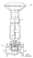
図1は、公知となっているスライディングステム弁組立体100を示す部分切欠き概略図である。アクチュエータ110は、弁組立体170の中に延びる弁棒140と結合されている。図2は、弁棒140を含む、図1の弁組立体170の一部を示す拡大図である。図2によりさらに明瞭に示されているように、弁棒140の端部148は、ネジ山143と、ある角度に傾斜した開口部146とを有している。弁組立体170は、弁オリフィス174および流出口176と連通する流入口172を有している。弁オリフィス174を流れる流体の流量は、弁体または弁部材180により制御されるようになっている。弁部材180は、ネジ山183が設けられた中央貫通孔182と、弁体孔184と、弁面185からある角度での弁面187に向けて延びる座ぐり孔186とを有している。弁棒140の端部148のネジ山143は、弁部材180のネジ山183により受けられるようになっている。図2から明らかなように、ピン190は、座ぐり孔186の直径よりわずかに大きくなっているが、弁部材180の座ぐり孔186および弁棒140のある角度で傾斜した開口部146の内部に配置されている。
FIG. 1 is a partial cutaway schematic diagram showing a known sliding
弁棒140は、当該弁棒140が弁部材180に対してほぼ垂直となるようにネジ山143を中央貫通孔182のネジ山183の中に螺合させることによって、弁部材180と結合されている。弁棒140が貫通孔182の中に堅固に螺合されたあと、座ぐり孔186が弁部材180の中に開けられ、開口部146が弁棒140の端部148の中に開けられる。次いで、ピン190が、座ぐり孔186および開口部146の中に圧入され、弁棒140を弁部材180に固定し、弁部材180が弁棒140に対して回転しないようになしてある(すなわち、回転する可能性をなくすようになしてある)。弁棒140は、中央貫通孔182の最上部のネジ山183と最上部のネジ山143との係合部で確固とした接点構成(solid contact alignment)を形成している。しかしながら、ピン190と弁棒140の端部148との係合部は弁面187の近傍にある。ピン190が弁棒140の中へ圧入される力により、弁棒140が弁部材180に対して垂直とならない角度(たとえば、位置ずれ状態)で設けられるおそれがある。位置ずれにより弁棒140が弁部材180に対して垂直でない場合、弁部材180の弁棒140への結合の統合性に対して影響を与えてしまうおそれがある。
The
弁棒を弁部材に接続させるための装置であって、 ネジ切りされた開口部を有する弁部材と、外周面にネジ山が設けられた弁棒であって、その端部にはこの弁棒の軸方向に延びる開口部が設けられ、外周面のネジ山が弁部材のネジ切りされた開口部により受けられる弁棒と、この弁棒の開口部に受けられる栓とを備えており、弁棒が弁部材の開口部内に螺合され、栓が弁棒の開口部に受けられて、弁棒の端部を直径方向に拡大させることにより弁棒を弁部材に固定するようになっている。 An apparatus for connecting a valve stem to a valve member, comprising: a valve member having a threaded opening; and a valve stem provided with a thread on an outer peripheral surface thereof; An opening extending in the axial direction of the valve member, and a valve stem whose outer peripheral thread is received by the threaded opening of the valve member, and a plug received by the opening of the valve stem, The rod is screwed into the opening of the valve member, the stopper is received by the opening of the valve rod, and the valve rod is fixed to the valve member by expanding the end of the valve rod in the diameter direction. .
一般的に、さまざまなタイプの組立体またはデバイスの部品間の接続に対して、本明細書に記載の弁部材に弁棒を接続するための例示の装置を用いることが可能である。これに加えて、本明細書に記載の実施例が、生産加工産業のための製品の流れの制御に関連して記述されているものの、より一般的にいえば、本明細書に記載の実施例は、さまざまな目的のさまざまな制御操作に対して適用可能である。 In general, the exemplary apparatus for connecting a valve stem to a valve member described herein can be used for connections between various types of assemblies or parts of a device. In addition, although the embodiments described herein have been described in connection with controlling product flow for the production and processing industry, more generally speaking, the implementations described herein. The examples are applicable for different control operations for different purposes.
図3には、弁部材280に弁棒240を接続するための例示の装置200が示されている。弁棒240は、当該弁棒240の端部242の外周に設けられたネジ山243を有している。さらに図4を参照すると、この端部242は、ネジ山246を有するネジ切りされた開口部244を備えている。スロット250が、ネジ切りされた開口部244に設けられ、弁棒240の長手方向の中心線または軸A−Aに対して平行となっている。スロット250は、弁棒240の端部242全体を横方向に貫通して延設されている。
In FIG. 3, an
図3に示されているように、弁部材280は、面285と面287との間に延設される中央貫通孔282を有し、当該貫通孔内にネジ山283を有している。弁棒240は、この中央貫通孔282の中へネジ込まれ、その中に着座するようになっている。テーパ形状の栓またはネジ切りされた部材300が雄ネジ302を有している(図5を参照)。図3を参照すると、テーパ形状の栓300の雄ネジ302は、端部242に隣接するネジ切りされた開口部244内のネジ山246により係合されている。栓300は、そのテーパ形状により、端部242に隣接するネジ山246としっかりと係合して開口部244内に保持されるようになっている。これに加えて、栓300を杭で支えること(杭を打ち込むこと)により、ネジ切りされた開口部244内で栓300を拡大させ(広げ)、栓300をその中にさらに固定させることができる。
As shown in FIG. 3, the
例示の装置200を組み立てるにあたって、弁棒240は、ネジ山243を中央貫通孔282のネジ山283に螺合させることにより、弁部材280に結合される。次いで、テーパ形状の栓300が、弁棒240のネジ切りされた開口部244の中に据え付けられるかまたは螺合される。テーパ形状の栓300を挿入させて端部242を直径方向外側に向けて拡大させることにより、弁棒240のネジ山243を中央貫通孔282のネジ山283としっかりと係合させる。この端部242の拡大は、ネジ切りされた開口部244内のスロット250により補助または促進される。スロット250は、端部242全体を貫通して端部242の横方向の拡大を等しいものとするとともに、端部242の位置合わせをより再現性のあるものとする。弁棒240は、最上部のネジ山243と中央貫通孔282の最上部のネジ山283との係合部において確固とした接点構成を達成するようになっている。また、弁棒240は、端部242に隣接する最下部のネジ山243と中央貫通孔282の最下部のネジ山283との係合部において確固とした接点構成を達成するようになっている。このようにして、端部242と弁部材280とが確固とした接点構成を達成することにより、弁棒240と弁部材280との間が非垂直となる位置ずれの発生を最小限に抑制するようになっている。
In assembling the
図6には、弁棒440を弁部材480に結合するための他の例示の装置400が示されている。装置400および弁棒440の弁部材480への接続のほとんどは、図3、図4および図5に関して先に記載されたこととほぼ同一であるので、簡潔にするため、図3、図4および図5との同一部分に関する説明は繰り返さないこととする。より正確にいえば、必要な読者は、図3、図4および図5の対応する記載を参照されたい。参照を容易にするために、図6の同一の部品には、図3、図4および図5の対応する部品の参照番号に200を加えた参照番号が付与されている。
FIG. 6 shows another
図6の例示の装置400は、弁棒440が弁部材480に堅固に取り付けられたままであることを担保するために追加のまたは任意選択的な構成部品を備えている。弁棒440が中央貫通孔482の中にしっかりと螺合され、テーパ形状の栓またはネジ切りされた部材500がネジ切りされた開口部444の中に挿入されたあと、単一の穿孔作業によって、座ぐり孔496を弁部材480の中に形成し、位置合わせされた孔もしくは通路456を端部442に形成し、位置合わせされた孔または通路をテーパ形状の栓500内に形成することができる。座ぐり孔496は拡大された孔部496Aを有していてもよい。座ぐり孔496および位置合わせされた孔または通路456、506は、弁棒440の長手方向の軸B−Bに対して約30度の角度で設けられている。ピン497は拡大された頭部498と、座ぐり孔496および通路456、506よりわずかに大きな直径を有したシャフト499とを備えている。ピン497のシャフト499は、座ぐり孔496および通路456、506の中に圧入され、拡大された頭部498が拡大された孔部496A内で受けられるようになっている。座ぐり孔496および通路456、506内にピン497を設けることで、弁部材と弁棒との間で回転が生じないようになるため、弁棒440を弁部材480に対して軸方向に固定することができる。
The
本明細書には幾つかの装置が記載されているが、本発明の技術範囲はこれらに限定されるものではない。もっと正確にいえば、本発明は、添付の特許請求の範囲に文字通りにまたは均等論に従って正当に含まれる製造の方法、装置および製品をすべて網羅するものである。 Although several apparatuses are described in this specification, the technical scope of the present invention is not limited to these. More precisely, the present invention covers all methods, devices and products of manufacture that are legally included in the appended claims literally or in accordance with an equivalent theory.
Claims (13)
ネジ切りされた開口部を有する弁部材と、
外周面にネジ山が設けられた弁棒であって、その端部にはこの弁棒の軸方向に延びる開口部が設けられ、前記外周面の前記ネジ山が前記弁部材の前記ネジ切りされた開口部に螺合されて受けられる弁棒と、
前記弁棒の前記開口部に受けられる栓とを備えており、
前記栓が前記弁棒の前記端部を直径方向に拡大させ、前記弁部材の前記ネジ切りされた開口部内に前記弁棒を螺合することと共同して前記弁棒を前記弁部材に固定するように構成され、
前記弁部材の表面と前記弁棒の前記開口部との間に延設される孔と、該孔の中に挿入されるピンとをさらに備え、
前記孔が、前記弁部材、前記弁棒および前記栓に孔を開けることにより形成され、
前記栓がさらに、ピンで支えられることにより前記弁棒の前記開口部内に保持されるように構成されてなる、装置。 A device for connecting a valve stem to a valve member,
A valve member having a threaded opening;
A valve stem having a thread on the outer peripheral surface, an opening extending in the axial direction of the valve stem is provided at an end thereof, and the thread on the outer peripheral surface is threaded of the valve member. A valve stem received by being screwed into the opening,
A stopper received in the opening of the valve stem,
The plug secures the valve stem to the valve member in conjunction with expanding the diametrically end of the valve stem and screwing the valve stem into the threaded opening of the valve member. Configured to
A hole extending between the surface of the valve member and the opening of the valve stem, and a pin inserted into the hole;
The hole is formed by opening a hole in the valve member, the valve stem, and the stopper;
The apparatus, wherein the plug is further configured to be retained within the opening of the valve stem by being supported by a pin.
前記角度が約30度である、請求項1に記載の装置。 The hole is provided to form an angle with respect to the longitudinal axis of the valve stem;
The apparatus of claim 1 , wherein the angle is about 30 degrees.
ネジ切りされた開口部を有する弁部材と、
外周面にネジ山が設けられた弁棒であって、その端部には軸方向に延びるネジ切りされた開口部が設けられ、スロットが前記弁棒の前記開口部に設けられ、前記外周面の前記ネジ山が前記弁部材の前記ネジ切りされた開口部により受けられる弁棒と、
前記弁棒の前記ネジ切りされた開口部に受けられるネジ切りされた部材とを備えており、
前記ネジ切りされた部材が前記弁棒の前記端部を直径方向に拡大させ、
前記弁棒が前記弁部材の前記開口部内に螺合され、前記ネジ切りされた部材が前記弁棒の前記ねじ切りされた開口部に受けられることにより前記弁棒を前記弁部材に固定するように構成され、
前記弁部材の表面と前記弁棒の前記開口部との間に延設される孔であって、前記弁棒の長手方向の軸に対してある角度を形成するように設けられてなる孔と、該孔の中に挿入されるピンとをさらに備え、
前記孔が、前記弁部材、前記弁棒および前記ネジ切りされた部材に孔を開けることにより形成されてなる、装置。 An apparatus for connecting a valve stem to a valve member of a control valve,
A valve member having a threaded opening;
A valve stem having a thread on the outer peripheral surface, the end of which is provided with a threaded opening extending in the axial direction, and a slot is provided in the opening of the valve stem, the outer peripheral surface A valve stem whose thread is received by the threaded opening of the valve member;
A threaded member received in the threaded opening of the valve stem;
The threaded member expands the end of the valve stem in a diametrical direction;
The valve stem is screwed into the opening of the valve member, and the threaded member is received by the threaded opening of the valve stem so that the valve stem is fixed to the valve member. Configured ,
A hole extending between the surface of the valve member and the opening of the valve stem, the hole being provided to form an angle with respect to the longitudinal axis of the valve stem; And a pin inserted into the hole,
The apparatus, wherein the hole is formed by making a hole in the valve member, the valve stem, and the threaded member .
Applications Claiming Priority (3)
| Application Number | Priority Date | Filing Date | Title |
|---|---|---|---|
| US11/711,428 | 2007-02-27 | ||
| US11/711,428 US7387292B1 (en) | 2007-02-27 | 2007-02-27 | Apparatus to connect a stem to a valve member |
| PCT/US2008/052635 WO2008106265A1 (en) | 2007-02-27 | 2008-01-31 | Apparatus to connect a stem to a valve member |
Publications (3)
| Publication Number | Publication Date |
|---|---|
| JP2010519489A JP2010519489A (en) | 2010-06-03 |
| JP2010519489A5 JP2010519489A5 (en) | 2012-03-22 |
| JP5244133B2 true JP5244133B2 (en) | 2013-07-24 |
Family
ID=39430778
Family Applications (1)
| Application Number | Title | Priority Date | Filing Date |
|---|---|---|---|
| JP2009551772A Active JP5244133B2 (en) | 2007-02-27 | 2008-01-31 | Device for connecting a valve stem to a valve member |
Country Status (8)
| Country | Link |
|---|---|
| US (1) | US7387292B1 (en) |
| EP (1) | EP2132450B1 (en) |
| JP (1) | JP5244133B2 (en) |
| CN (1) | CN101595315B (en) |
| BR (1) | BRPI0806924B1 (en) |
| CA (1) | CA2674396C (en) |
| MX (1) | MX2009008930A (en) |
| WO (1) | WO2008106265A1 (en) |
Families Citing this family (10)
| Publication number | Priority date | Publication date | Assignee | Title |
|---|---|---|---|---|
| US8752809B2 (en) * | 2010-03-03 | 2014-06-17 | Fisher Controls International, Llc | Methods and apparatus to couple valve shafts and closure members |
| US9010720B2 (en) * | 2011-03-18 | 2015-04-21 | Fisher Controls International, Llc | Thermally compensated valve trim apparatus |
| CN102518870A (en) * | 2011-12-23 | 2012-06-27 | 中国石化销售有限公司华南分公司 | Device for connecting valve rod to valve member |
| US9022070B2 (en) * | 2012-07-16 | 2015-05-05 | Fisher Controls International Llc | Bolted valve control element |
| US9746095B2 (en) | 2013-07-17 | 2017-08-29 | Fisher Controls International Llc | Apparatus to attach a fluid valve bonnet |
| CN106763942A (en) * | 2015-11-20 | 2017-05-31 | 镇江液压股份有限公司 | A kind of self-locking type safety valve |
| JP6762165B2 (en) * | 2016-08-26 | 2020-09-30 | アズビル株式会社 | Control valve |
| DE102017123308B4 (en) * | 2017-10-06 | 2022-09-08 | Samson Ag | control valve |
| US10920908B2 (en) * | 2018-01-22 | 2021-02-16 | DDS Investments, LLC | Valve stem for choke valve |
| CN110671506A (en) * | 2019-10-17 | 2020-01-10 | 太原纳新食品有限公司 | Lock nut type double-seal ring valve |
Family Cites Families (24)
| Publication number | Priority date | Publication date | Assignee | Title |
|---|---|---|---|---|
| US918288A (en) * | 1908-05-26 | 1909-04-13 | Thomas Crowe | Faucet, tap, valve, ball-cock, and the like. |
| US941652A (en) * | 1908-07-09 | 1909-11-30 | Edward A Field | Air-hose coupling. |
| US1686849A (en) * | 1927-10-15 | 1928-10-09 | Aloysius M Frauenheim | Fluid valve |
| US2057150A (en) * | 1932-03-21 | 1936-10-13 | Union Carbide & Carbon Corp | Two-stage pressure regulator |
| US1985149A (en) * | 1933-12-09 | 1934-12-18 | Chapple Charles Edwin | Faucet valve |
| US2121315A (en) * | 1936-05-28 | 1938-06-21 | Ridge Tool Co | Valve washer |
| US2277251A (en) * | 1941-01-16 | 1942-03-24 | Edson F Palmer | Packing washer |
| US2457492A (en) * | 1944-05-22 | 1948-12-28 | Weatherhead Co | Valve |
| FR1113215A (en) * | 1954-10-26 | 1956-03-26 | Nail or internal jam screw | |
| US2930401A (en) * | 1956-11-16 | 1960-03-29 | Bobrick Mfg Corp | Poppet valve construction |
| US3059895A (en) * | 1957-05-31 | 1962-10-23 | Parker Hannifin Corp | Probe terminal assembly for in-flight re-fueling |
| FR2034598A1 (en) * | 1969-03-03 | 1970-12-11 | Wada Takeji | |
| JPS60127111U (en) * | 1984-01-30 | 1985-08-27 | 佐藤螺旋株式会社 | fastener |
| JPS6232218U (en) * | 1985-08-13 | 1987-02-26 | ||
| CN2050902U (en) * | 1989-05-23 | 1990-01-10 | 范文林 | Bolt guarding against theft |
| CN2093260U (en) * | 1990-05-07 | 1992-01-15 | 朱伟琪 | Expansion bolt |
| US5201335A (en) | 1991-10-15 | 1993-04-13 | Fisher Controls International, Inc. | Method and apparatus for attaching ceramic to metal parts |
| US5244323A (en) * | 1993-02-03 | 1993-09-14 | The United States Of America As Represented By The Secretary Of The Navy | Self locking set screw |
| EP1050691A3 (en) * | 1999-05-03 | 2003-04-02 | Junker & Partner GmbH | Screw locking device |
| JP2001032951A (en) * | 1999-07-19 | 2001-02-06 | Kubota Corp | Gate valve |
| DE19937955B4 (en) * | 1999-08-11 | 2005-04-21 | Framatome Anp Gmbh | Screwing device and method for locking a nut |
| US20030074792A1 (en) * | 2001-10-18 | 2003-04-24 | Fisher Controls International, Inc. | Connecting and locking stems for valves and other devices |
| US6878890B1 (en) * | 2003-12-19 | 2005-04-12 | Eaton Corporation | Circuit breaker lockable fastener securing a movable contact to its terminal mounting |
| JP2005249084A (en) * | 2004-03-04 | 2005-09-15 | Katsuhiro Ouchi | Locking mechanism of screw |
-
2007
- 2007-02-27 US US11/711,428 patent/US7387292B1/en active Active
-
2008
- 2008-01-31 JP JP2009551772A patent/JP5244133B2/en active Active
- 2008-01-31 MX MX2009008930A patent/MX2009008930A/en active IP Right Grant
- 2008-01-31 WO PCT/US2008/052635 patent/WO2008106265A1/en active Application Filing
- 2008-01-31 BR BRPI0806924A patent/BRPI0806924B1/en not_active IP Right Cessation
- 2008-01-31 CA CA2674396A patent/CA2674396C/en active Active
- 2008-01-31 CN CN200880002936.0A patent/CN101595315B/en active Active
- 2008-01-31 EP EP08728700.9A patent/EP2132450B1/en active Active
Also Published As
| Publication number | Publication date |
|---|---|
| BRPI0806924A2 (en) | 2014-04-29 |
| EP2132450A1 (en) | 2009-12-16 |
| EP2132450B1 (en) | 2014-03-12 |
| CA2674396A1 (en) | 2008-09-04 |
| CN101595315B (en) | 2015-01-21 |
| CA2674396C (en) | 2014-10-21 |
| MX2009008930A (en) | 2009-08-28 |
| BRPI0806924B1 (en) | 2019-08-13 |
| WO2008106265A1 (en) | 2008-09-04 |
| JP2010519489A (en) | 2010-06-03 |
| US7387292B1 (en) | 2008-06-17 |
| CN101595315A (en) | 2009-12-02 |
Similar Documents
| Publication | Publication Date | Title |
|---|---|---|
| JP5244133B2 (en) | Device for connecting a valve stem to a valve member | |
| JP2010534802A (en) | Device for connecting the valve stem to the disc | |
| KR101284749B1 (en) | Flow control valve | |
| EP3462064B1 (en) | Flow control valve | |
| JP6450499B2 (en) | Electronic expansion valve | |
| WO2016130740A2 (en) | Valve stem and plug connections and staking tools | |
| EP3526498B1 (en) | Yoke for rotary valve | |
| US20160017903A1 (en) | Fluid throttle member | |
| JP5078893B2 (en) | Control valve | |
| JP5175135B2 (en) | Flow control valve | |
| US10619746B2 (en) | Regulating valve, valve body, valve stem, and locking member | |
| CN113932018A (en) | Electronic expansion valve | |
| MX2012010176A (en) | Method and apparatus to couple valve shafts and closure member. | |
| US20190264817A1 (en) | Tapered nut valve plug fasteners | |
| US10753481B2 (en) | Regulating valve, valve body, and valve stem | |
| JP2009281527A (en) | Relief valve | |
| JP5242443B2 (en) | Valve device | |
| JP2011075079A (en) | Ball valve | |
| CN211649114U (en) | Straight stroke sleeve regulating valve | |
| CN216201039U (en) | Shaft sleeve for valve | |
| JP5303226B2 (en) | Double seat valve | |
| DE202009017102U1 (en) | Self-balancing, self-compensating, encapsulated tap | |
| KR101797732B1 (en) | Ball Valves Having Shaft through the ball | |
| JP6054221B2 (en) | Butterfly type steam valve | |
| RU2006128533A (en) | WELDED VALVE SHUT-OFF |
Legal Events
| Date | Code | Title | Description |
|---|---|---|---|
| A521 | Request for written amendment filed |
Free format text: JAPANESE INTERMEDIATE CODE: A523 Effective date: 20110111 |
|
| A621 | Written request for application examination |
Free format text: JAPANESE INTERMEDIATE CODE: A621 Effective date: 20110111 |
|
| A521 | Request for written amendment filed |
Free format text: JAPANESE INTERMEDIATE CODE: A523 Effective date: 20120202 |
|
| A977 | Report on retrieval |
Free format text: JAPANESE INTERMEDIATE CODE: A971007 Effective date: 20121122 |
|
| A131 | Notification of reasons for refusal |
Free format text: JAPANESE INTERMEDIATE CODE: A131 Effective date: 20121127 |
|
| A521 | Request for written amendment filed |
Free format text: JAPANESE INTERMEDIATE CODE: A523 Effective date: 20130128 |
|
| TRDD | Decision of grant or rejection written | ||
| A01 | Written decision to grant a patent or to grant a registration (utility model) |
Free format text: JAPANESE INTERMEDIATE CODE: A01 Effective date: 20130319 |
|
| A61 | First payment of annual fees (during grant procedure) |
Free format text: JAPANESE INTERMEDIATE CODE: A61 Effective date: 20130405 |
|
| FPAY | Renewal fee payment (event date is renewal date of database) |
Free format text: PAYMENT UNTIL: 20160412 Year of fee payment: 3 |
|
| R150 | Certificate of patent or registration of utility model |
Free format text: JAPANESE INTERMEDIATE CODE: R150 Ref document number: 5244133 Country of ref document: JP Free format text: JAPANESE INTERMEDIATE CODE: R150 |
|
| R250 | Receipt of annual fees |
Free format text: JAPANESE INTERMEDIATE CODE: R250 |
|
| R250 | Receipt of annual fees |
Free format text: JAPANESE INTERMEDIATE CODE: R250 |
|
| R250 | Receipt of annual fees |
Free format text: JAPANESE INTERMEDIATE CODE: R250 |
|
| R250 | Receipt of annual fees |
Free format text: JAPANESE INTERMEDIATE CODE: R250 |
|
| R250 | Receipt of annual fees |
Free format text: JAPANESE INTERMEDIATE CODE: R250 |