JP5243017B2 - Passenger conveyor drive - Google Patents

Passenger conveyor drive Download PDF

Info

Publication number
JP5243017B2
JP5243017B2 JP2007331776A JP2007331776A JP5243017B2 JP 5243017 B2 JP5243017 B2 JP 5243017B2 JP 2007331776 A JP2007331776 A JP 2007331776A JP 2007331776 A JP2007331776 A JP 2007331776A JP 5243017 B2 JP5243017 B2 JP 5243017B2
Authority
JP
Japan
Prior art keywords
passenger conveyor
gear box
gear
opening
mounting seat
Prior art date
Legal status (The legal status is an assumption and is not a legal conclusion. Google has not performed a legal analysis and makes no representation as to the accuracy of the status listed.)
Active
Application number
JP2007331776A
Other languages
Japanese (ja)
Other versions
JP2009154982A (en
Inventor
敏行 福田
啓輔 竹本
智典 山下
Current Assignee (The listed assignees may be inaccurate. Google has not performed a legal analysis and makes no representation or warranty as to the accuracy of the list.)
Hitachi Ltd
Original Assignee
Hitachi Ltd
Priority date (The priority date is an assumption and is not a legal conclusion. Google has not performed a legal analysis and makes no representation as to the accuracy of the date listed.)
Filing date
Publication date
Application filed by Hitachi Ltd filed Critical Hitachi Ltd
Priority to JP2007331776A priority Critical patent/JP5243017B2/en
Priority to CN2008101852554A priority patent/CN101468773B/en
Publication of JP2009154982A publication Critical patent/JP2009154982A/en
Application granted granted Critical
Publication of JP5243017B2 publication Critical patent/JP5243017B2/en
Active legal-status Critical Current
Anticipated expiration legal-status Critical

Links

Images

Description

本発明は隣接踏板に段差が生じるエスカレーターや隣接踏板間に段差が生じない電動道路等の乗客コンベアの駆動装置に係り、特に、歯車箱の上に駆動用電動機を支持した乗客コンベアの駆動装置に関する。   TECHNICAL FIELD The present invention relates to an escalator in which a step is formed on adjacent treads and a drive device for a passenger conveyor such as an electric road where no step is generated between adjacent treads, and more particularly to a drive device for a passenger conveyor that supports a drive motor on a gear box. .

設置スペースの縮小や部品数の低減を目的に、歯車箱の上部に駆動用電動機を支持した乗客コンベアの駆動装置は、例えば特許文献1,2に開示されているように、既に提案されている。   For the purpose of reducing the installation space and reducing the number of parts, a passenger conveyor driving device that supports a driving motor on the top of a gear box has already been proposed as disclosed in, for example, Patent Documents 1 and 2. .

特開平6−87591号公報JP-A-6-87591 特開平6−92579号公報JP-A-6-92579

上記特許文献1に開示された乗客コンベアの駆動装置は、歯車箱上に直接駆動用電動機を取付けている。そのために、歯車箱内に歯車を組み込む際に、歯車箱を上下二分割構成にしなければならない。その結果、上下二分割面の機械加工を精密にしなければ潤滑油が歯車箱外に漏洩するので、機械加工が厄介になると共に、分割面の精度が要求される部品数が多くなる問題がある。   In the passenger conveyor driving device disclosed in Patent Document 1, a driving motor is directly mounted on a gear box. Therefore, when the gear is incorporated in the gear box, the gear box must be divided into two parts. As a result, if the machining of the upper and lower split surfaces is not precise, the lubricating oil will leak out of the gearbox, making machining difficult and increasing the number of parts that require precision on the split surfaces. .

一方、特許文献2に開示された乗客コンベアの駆動装置は、歯車箱上に開口部を設けているので、この開口部から歯車を歯車箱内に組み込むことができる。しかし、歯車箱の開口部を塞ぐ塞ぎ部材が必要となり、そのために歯車箱とは別構成の塞ぎ部材を用意し、この塞ぎ部材に駆動用電動機を固定するように構成している。このために、塞ぎ部材の歯車箱に対向する面と駆動用電動機を固定する取付面とを精度よく機械加工しなければ精度の良い駆動用電動機の据付けができず、その結果、精度が要求される部品数が増加すると共に精度が要求される機械加工が必要となる新たな問題が発生する。   On the other hand, the passenger conveyor drive device disclosed in Patent Document 2 is provided with an opening on the gear box, so that the gear can be incorporated into the gear box from this opening. However, a closing member for closing the opening of the gear box is required. For this purpose, a closing member having a configuration different from that of the gear box is prepared, and the driving motor is fixed to the closing member. For this reason, if the surface facing the gear box of the closing member and the mounting surface for fixing the driving motor cannot be machined with high accuracy, the driving motor cannot be installed with high accuracy, and as a result, accuracy is required. As the number of parts increases, new problems arise that require machining that requires high precision.

本発明の目的は、精度が要求される部品数を低減して機械加工を少なくした乗客コンベアの駆動装置を提供することにある。   An object of the present invention is to provide a driving device for a passenger conveyor that reduces the number of parts that require accuracy and reduces machining.

本発明は上記目的を達成するために、歯車箱の頂部に開口部を形成し、この開口部の周縁に前記駆動用電動機の取付脚を固定する取付座を形成したのである。   In order to achieve the above object, the present invention has an opening formed at the top of the gear box, and a mounting seat for fixing the mounting leg of the driving motor is formed around the periphery of the opening.

このように歯車箱の開口部周縁に駆動用電動機を取付ける取付座を形成したので、精度よい機械加工は取付座の取付座面だけでよく、また、駆動用電動機の支持を兼ね精度が要求される別部材の開口部の塞ぎ部材が不要になるので、精度が要求される部品数を低減することができる。   Since the mounting seat for mounting the drive motor is formed on the periphery of the opening of the gear box in this way, accurate machining is only required for the mounting seat surface of the mounting seat, and accuracy is also required to support the drive motor. Therefore, the number of parts requiring high accuracy can be reduced.

したがって、精度が要求される部品数を低減して機械加工を少なくした乗客コンベアの駆動装置を得ることができる。   Therefore, it is possible to obtain a passenger conveyor drive device that reduces the number of parts that require accuracy and reduces machining.

以下、本発明による乗客コンベアの駆動装置の一実施の形態を図1〜図4に基づいて説明する。   Hereinafter, an embodiment of a passenger conveyor drive device according to the present invention will be described with reference to FIGS.

図4は、乗客コンベアとしてエスカレーター1を示すもので、このエスカレーター1は、上下階床に跨って設置され上部水平枠2Aと中間傾斜枠2Bと下部水平枠2Cとから構成された枠体2と、上部水平枠2A内に軸支された駆動スプロケット3と、下部水平枠2C内に軸支された従動スプロケット4と、これら駆動スプロケット3と従動スプロケット4とに跨って無端状に巻き掛けられた踏段チェーン5と、この踏段チェーン5に連結され往路側では常に水平に保持される踏板を有する複数の踏段6と、前記枠体2の踏段6の幅方向両側に対応する位置に沿って立設された欄干パネル7と、この欄干パネル7の周縁に案内されて移動する移動手摺8と、前記踏段チェーン5や移動手摺8の駆動ぶとなる駆動装置9とを備えている。   FIG. 4 shows an escalator 1 as a passenger conveyor. The escalator 1 is installed across the upper and lower floors, and includes a frame 2 composed of an upper horizontal frame 2A, an intermediate inclined frame 2B, and a lower horizontal frame 2C. The drive sprocket 3 supported in the upper horizontal frame 2A, the driven sprocket 4 supported in the lower horizontal frame 2C, and the drive sprocket 3 and the driven sprocket 4 were wound endlessly. A plurality of steps 6 having a step chain 5, a step plate connected to the step chain 5 and always kept horizontal on the forward path side, and standing along positions corresponding to both sides in the width direction of the step 6 of the frame 2 And a moving handrail 8 that moves while being guided by the periphery of the balustrade panel 7, and a driving device 9 that drives the step chain 5 and the moving handrail 8.

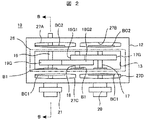
駆動装置9は、減速機10と駆動用電動機11とを備えている。減速機10は、図1〜図3に示すように、角型の直方体をなし上部に開口部13を有する歯車箱12と、この歯車箱12の開口部13の周縁に形成された取付座14と、歯車箱12の下部に形成され歯車箱12をエスカレーター1の固定部材(例えば上部水平枠2A)に取付ける固定座15とを有している。一方、上記駆動用電動機11は、前記取付座14の取付座面14Sにボルトやナットで固定される取付脚16を有している。   The drive device 9 includes a speed reducer 10 and a drive motor 11. As shown in FIGS. 1 to 3, the speed reducer 10 is a gear box 12 having a rectangular parallelepiped shape and having an opening 13 at the top, and a mounting seat 14 formed on the periphery of the opening 13 of the gear box 12. And a fixing seat 15 which is formed at the lower part of the gear box 12 and attaches the gear box 12 to a fixing member (for example, the upper horizontal frame 2A) of the escalator 1. On the other hand, the driving motor 11 has mounting legs 16 fixed to the mounting seat surface 14S of the mounting seat 14 with bolts or nuts.

また、歯車箱10は、直方体の幅狭方向に対向する側壁12A,12Bに複数の軸受B1,B2を支持させ、これら軸受B1,B2に入力軸17,中間軸18,出力軸19を支承させている。これら入力軸17,中間軸18,出力軸19には、例えば、はすば歯車による夫々入力歯車17Gと中間歯車18G1,18G2と出力歯車19Gを固定して平行軸歯車を構成している。また、歯車箱10から外側に突出した入力軸17にはボスを介して入力スプロケット20が固定され、出力軸19にはボスを介して出力スプロケット21が固定されている。そして、軸受B1,B2の周囲には歯車箱10の外側から軸受カバーBC1,BC2が施されている。   Further, the gear box 10 supports a plurality of bearings B1 and B2 on side walls 12A and 12B opposed to each other in the narrow direction of the rectangular parallelepiped, and supports the input shaft 17, the intermediate shaft 18 and the output shaft 19 on these bearings B1 and B2. ing. The input shaft 17, the intermediate shaft 18, and the output shaft 19 are, for example, fixed to the input gear 17G, the intermediate gears 18G1, 18G2, and the output gear 19G made of helical gears to constitute parallel shaft gears. An input sprocket 20 is fixed to the input shaft 17 protruding outward from the gear box 10 via a boss, and an output sprocket 21 is fixed to the output shaft 19 via a boss. Then, bearing covers BC1 and BC2 are provided around the bearings B1 and B2 from the outside of the gear box 10.

そして、駆動用電動機11の回転軸に設けたスプロケット22と前記入力スプロケット20とに動力伝達チェーン23を巻き掛けると共に、前記出力スプロケット21と前記駆動スプロケット3と同軸の動力伝達スプロケット(図示せず)との間に動力伝達チェーン24を巻き掛けている。ここで、入力スプロケット20とスプロケット22と動力伝達チェーン23とが本発明による駆動用電動機11の動力を入力軸17達する第1の伝達手段となり、出力スプロケット21、駆動スプロケット3と同軸の動力伝達スプロケット(図示せず)及び動力伝達チェーン24が本発明による出力軸19から乗客コンベア(エスカレーター)の踏板や移動手摺の駆動部に動力を伝達する第2の伝達手段となる。駆動スプロケット3と同軸の動力伝達スプロケット(図示せず)に伝達された動力は、駆動スプロケット3を介して複数の踏段6を駆動すると共に、手摺駆動機構(図示せず)を介して移動手摺8を駆動している。   A power transmission chain 23 is wound around the sprocket 22 provided on the rotating shaft of the drive motor 11 and the input sprocket 20, and a power transmission sprocket coaxial with the output sprocket 21 and the drive sprocket 3 (not shown). A power transmission chain 24 is wound between the two. Here, the input sprocket 20, the sprocket 22, and the power transmission chain 23 become the first transmission means for reaching the input shaft 17 with the power of the driving motor 11 according to the present invention, and the power transmission sprocket coaxial with the output sprocket 21 and the driving sprocket 3. The power transmission chain 24 (not shown) and the power transmission chain 24 serve as second transmission means for transmitting power from the output shaft 19 according to the present invention to the stepping plate of the passenger conveyor (escalator) and the driving unit of the moving handrail. The power transmitted to a power transmission sprocket (not shown) coaxial with the drive sprocket 3 drives a plurality of steps 6 via the drive sprocket 3 and a moving handrail 8 via a handrail drive mechanism (not shown). Is driving.

このほかエスカレーター1には、図示は省略するが各種安全装置や自動運転装置、さらには省エネルギー運転手段が設けられているが、これらは制御装置25を経由した指令に基づいて運転制御されている。さらに、歯車箱12の内部には潤滑油が入っており、この潤滑油が各種歯車17G,18G,19Gの回転によって開口部13から飛び出ることがあるので、取付座14に薄鋼板や樹脂板等からなる塞ぎ部材26をビス止めして前記開口部13を塞いでいる。このように塞ぐことで、潤滑油の飛び跳ねや塵埃の歯車箱12内への侵入を防止することができる。尚、塞ぎ部材26を設けることで部品数が増えるが、この塞ぎ部材26は精度を要求されるものではないので、精度が要求される部品を増加させることにはならない。また、塞ぎ部材26を単独で用いずに、駆動用電動機11の取付脚16側に溶接やビス止め等で一体に取付けておくことにより、取付座14へのビス止め作業を廃止したり、塞ぎ部材26の紛失を防止したりすることができる。   In addition, although not shown in the drawing, the escalator 1 is provided with various safety devices, automatic operation devices, and energy saving operation means, which are controlled for operation based on a command via the control device 25. Furthermore, since the lubricating oil is contained in the gear box 12, and this lubricating oil may jump out of the opening 13 due to the rotation of the various gears 17G, 18G, 19G, a thin steel plate, a resin plate, etc. The opening member 13 is closed by screwing a closing member 26 made of a screw. By closing in this way, it is possible to prevent the splashing of the lubricating oil and the intrusion of dust into the gear box 12. Although the number of parts is increased by providing the closing member 26, the closing member 26 is not required to be accurate, so that the number of parts required for accuracy is not increased. In addition, the screw fixing work to the mounting seat 14 can be abolished or closed by attaching the welding member 26 integrally to the mounting leg 16 side of the driving motor 11 by welding or screwing without using the closing member 26 alone. The loss of the member 26 can be prevented.

さらに、各種歯車17G,18G,19Gを歯車箱12内に組み込む場合には、まず、両側に軸受B1,B2を装着しその中間に中間歯車18G1,18G2を固定した中間軸18を、歯車箱12の開口部13側から挿入し、軸受B1,B2を側壁12A,12Bの内側に設けた軸受保持部に保持させる。その後、軸受箱12内に小歯車17G,大歯車19Gを保持した状態で、入力軸17,出力軸19の一端を側壁12A,12Bを貫通して設置した軸受B1,B2のうち一方側の軸受を貫通させ、次に、入力歯車17G,出力歯車19Gを貫通させ,最後に他方側の軸受を貫通させることで、平行軸歯車を組み込むことができる。したがって、歯車箱12を各軸17〜19の位置で上下に分割する必要はなく、分割の必要がないことから、当然従来において必要としていた分割面の機械加工も不要となる。   Further, when incorporating the various gears 17G, 18G, and 19G into the gear box 12, first, the intermediate shaft 18 having the bearings B1 and B2 mounted on both sides and the intermediate gears 18G1 and 18G2 being fixed therebetween is connected to the gear box 12. The bearings B1 and B2 are held by bearing holding portions provided inside the side walls 12A and 12B. Thereafter, in a state where the small gear 17G and the large gear 19G are held in the bearing housing 12, one end of the bearings B1 and B2 in which one end of the input shaft 17 and the output shaft 19 is installed through the side walls 12A and 12B. Next, the input gear 17G and the output gear 19G are penetrated, and finally the other side bearing is penetrated, whereby a parallel shaft gear can be incorporated. Therefore, it is not necessary to divide the gear box 12 vertically at the positions of the respective shafts 17 to 19, and it is not necessary to divide the gear box 12.

このほか、本実施の形態においては、歯車箱12の開口部13の周縁に形成された取付座14に、平面的に動力伝達チェーン23の張架方向に平行となる方向に沿った、云い代えれば、平面的に歯車軸と直交する方向に沿つた長円形のボルト貫通孔27a〜 27Dが設けられている。このため、動力伝達チェーン23に多少の長短が生じても、取付座14の上を駆動用電動機11の取付脚16を動力伝達チェーン23の張架方向に平行移動させて動力伝達チェーン23を適切な張力で張架されるように調整し、その後、ボルトにより固定することで、容易に動力伝達チェーン23の張架調整を行なうことができる。また、このボルト貫通孔27a〜 27Dが歯車箱12の取付座14に設けられているので、駆動用電動機11のスプロケット22と減速機10の入カスプロケット20との芯出し作業を簡略化できる。
In addition, in this embodiment, the mounting seat 14 formed on the periphery of the opening 13 of the gear box 12 is replaced with a plane along a direction parallel to the stretching direction of the power transmission chain 23 in a plane. For example, oval bolt through-holes 27a to 27D are provided along a plane perpendicular to the gear shaft. For this reason, even if the power transmission chain 23 is slightly longer or shorter, the mounting leg 16 of the driving motor 11 is translated on the mounting seat 14 in the stretching direction of the power transmission chain 23 so that the power transmission chain 23 is properly It is possible to easily adjust the tension of the power transmission chain 23 by adjusting the tension so that the power transmission chain 23 is tensioned and then fixing with a bolt. Further, since the bolt through holes 27a to 27D are provided in the mounting seat 14 of the gear box 12, the centering operation between the sprocket 22 of the drive motor 11 and the input crest 20 of the speed reducer 10 can be simplified.

このほか、従来における歯車箱12とは別体の、駆動用電動機11の固定を兼用する歯車箱12の開口部を塞ぐ塞ぎ部材が不要になる分、駆動装置9の高さ寸法を縮小することができるので、駆動装置9の狭い枠体2内の設置を有利にすることができる。   In addition, the height of the drive device 9 is reduced by the amount that eliminates the need for a closing member that closes the opening of the gear box 12 that also serves to fix the drive motor 11 separately from the conventional gear box 12. Therefore, the installation of the driving device 9 in the narrow frame 2 can be made advantageous.

本実施の形態によれば、歯車箱12の上部に開口部13を形成し、その周縁に取付座14を形成して駆動用電動機11の取付脚16を歯車箱12に直接支持固定するようにしているので、駆動用電動機11を歯車箱12に取付けるための精度が要求される専用の部品を必要とすることがなく、その結果、精度が要求される部品数を低減することができる。さらに、精度を要する機械加工は駆動用電動機11を取付ける取付座14の取付座面14Sだけでよく、そのため精密な機械加工作業を少なくすることができる。   According to the present embodiment, the opening 13 is formed in the upper part of the gear box 12 and the mounting seat 14 is formed in the periphery thereof so that the mounting leg 16 of the driving motor 11 is directly supported and fixed to the gear box 12. Therefore, there is no need for a dedicated component that requires accuracy for mounting the drive motor 11 to the gear box 12, and as a result, the number of components that require accuracy can be reduced. Furthermore, the machining that requires accuracy is only the mounting seat surface 14S of the mounting seat 14 to which the drive motor 11 is attached, and therefore, precise machining operations can be reduced.

尚、上記実施の形態は乗客コンベアとしてエスカレーター1を説明したが、本発明は電動道路にも適用できることは云うまでもない。   In addition, although the said embodiment demonstrated the escalator 1 as a passenger conveyor, it cannot be overemphasized that this invention is applicable also to an electric road.

本発明による乗客コンベアの駆動装置を示す側面図。The side view which shows the drive device of the passenger conveyor by this invention. 図1のA−A線に沿う平面図。The top view which follows the AA line of FIG. 図1のB−B線に沿う縦断正面図。The longitudinal section front view which follows the BB line of FIG. 本発明の乗客コンベアの駆動装置が適用されたエスカレーターを示す概略側面図。The schematic side view which shows the escalator to which the drive device of the passenger conveyor of this invention was applied.

符号の説明Explanation of symbols

1…エスカレーター、2…枠体、2A…上部水平枠、2B…中間傾斜枠、2C…下部水平枠、3…駆動スプロケット、4…従動スプロケット、5…踏段チェーン、6…踏段、7…欄干パネル、8…移動手摺、9…駆動装置、10…減速機、11…駆動用電動機、12…歯車箱、13…開口部、14…取付座、14S…取付座面、15…固定座、16…取付脚、17…入力軸、18…中間軸、19…出力軸、17G…入力歯車、18G1,18G2…中間歯車、19G…出力歯車、20…入力スプロケット、21…出力スプロケット、22…スプロケット、23,24…動力伝達チェーン、25…制御装置、26…塞ぎ部材、27A〜27D…ボルト貫通孔、B1,B2…軸受、BC1,BC2…軸受カバー。   DESCRIPTION OF SYMBOLS 1 ... Escalator, 2 ... Frame body, 2A ... Upper horizontal frame, 2B ... Intermediate inclination frame, 2C ... Lower horizontal frame, 3 ... Drive sprocket, 4 ... Drive sprocket, 5 ... Step chain, 6 ... Step, 7 ... Railing panel , 8 ... moving handrail, 9 ... driving device, 10 ... reduction gear, 11 ... driving motor, 12 ... gear box, 13 ... opening, 14 ... mounting seat, 14S ... mounting seat surface, 15 ... fixed seat, 16 ... Mounting legs, 17 ... input shaft, 18 ... intermediate shaft, 19 ... output shaft, 17G ... input gear, 18G1, 18G2 ... intermediate gear, 19G ... output gear, 20 ... input sprocket, 21 ... output sprocket, 22 ... sprocket, 23 , 24 ... power transmission chain, 25 ... control device, 26 ... closing member, 27A to 27D ... bolt through hole, B1, B2 ... bearing, BC1, BC2 ... bearing cover.

Claims (7)

複数の歯車を軸支した歯車箱と、この歯車箱の上に支持された駆動用電動機と、この駆動用電動機の動力を前記複数の歯車を介して乗客コンベアの踏板の駆動部及び移動手摺の駆動部に伝達する乗客コンベアの駆動装置において、前記歯車箱の頂部に開口部を形成し、この開口部の周縁に前記駆動用電動機の取付脚を前記歯車箱に直接支持固定する取付座を形成し、かつ前記開口部を塞ぐ塞ぎ部材を前記取付座とは別部品で設けたことを特徴とする乗客コンベアの駆動装置。 A gear box that pivotally supports a plurality of gears, a driving motor supported on the gear box, and the power of the driving motor via the plurality of gears, In the driving device for the passenger conveyor that transmits to the driving unit, an opening is formed at the top of the gear box, and a mounting seat for directly supporting and fixing the mounting leg of the driving motor to the gear box is formed at the periphery of the opening. And a driving device for a passenger conveyor, wherein a closing member for closing the opening is provided as a separate component from the mounting seat . 前記塞ぎ部材は、薄鋼板または樹脂板で形成されていることを特徴とする請求項1に記載の乗客コンベアの駆動装置。2. The passenger conveyor drive device according to claim 1, wherein the closing member is formed of a thin steel plate or a resin plate. 記歯車箱の下部にはこの歯車箱を乗客コンベアの固定部材に取付ける固定座を設けたことを特徴とする請求項1又は2に記載の乗客コンベアの駆動装置。 Driving device for a passenger conveyor according to claim 2, characterized in that a fixing seat for mounting the gearbox to a fixed member of the passenger conveyor the bottom of the front Symbol gearbox. 記塞ぎ部材は、前記駆動用電動機側に一体に設けられていることを特徴とする請求項1〜3の何れかに記載の乗客コンベアの駆動装置。 Before SL closing member, the driving device of passenger conveyor according to any one of claims 1 to 3, characterized in that provided integrally with the driving motor side. 記塞ぎ部材は、前記駆動用電動機側とは別体に設けられていることを特徴とする請求項1〜3の何れかに記載の乗客コンベアの駆動装置。 Before SL closing member, the driving device of passenger conveyor according to any one of claims 1 to 3, characterized in that is provided separately from said driving motor side. 前記取付座には、駆動用電動機の取付脚をボルトで固定するためのボルト貫通孔が形成されており、このボルト貫通孔は平面的に歯車軸と直交する方向に沿った長円形に形成されていることを特徴とする請求項1〜5の何れかに記載の乗客コンベアの駆動装置。 The mounting seat is formed with a bolt through hole for fixing the mounting leg of the driving motor with a bolt, and the bolt through hole is formed in an oval shape along a direction perpendicular to the gear shaft in a plan view. The drive device for a passenger conveyor according to any one of claims 1 to 5. 歯車箱と、この歯車箱の上部に形成した開口部と、歯車箱の対向する両側壁に固定された複数の軸受と、これら軸受に軸支されて噛合う複数の平行軸歯車と、前記開口部の周縁に形成され駆動用電動機の取付脚を前記歯車箱に直接支持固定する固定する取付座と、前記歯車箱の下部に形成され歯車箱を乗客コンベアの固定部材に取付ける固定座と、前記取付座とは別部品の前記開口部を塞ぐ塞ぎ部材とを備え、前記複数の平行軸歯車のうち一つの平行軸歯車の回転軸を入力軸とし、残る一つの平行軸歯車の回転軸を出力軸とし、かつ、前記駆動用電動機の動力を前記入力軸に伝達する第1の伝達手段と、前記出力軸から乗客コンベアの駆動部に動力を伝達する第2の伝達手段とを設けると共に、前記取付座には前記駆動用電動機をボルト固定するためボルト貫通孔が形成されており、このボルト貫通孔は平面的に歯車軸と直交する方向に沿った長円形に形成されており、さらに、前記開口部は複数の平行軸歯車を搬出入する大きさに形成されていることを特徴とする乗客コンベアの駆動装置。 A gear box, an opening formed in an upper portion of the gear box, a plurality of bearings fixed to opposite side walls of the gear box, a plurality of parallel shaft gears supported by and supported by the bearings, and the opening a mounting seat for a peripheral edge formed attachment leg of the drive motor parts fixed support fixed directly to the gearbox, a fixing seat for mounting the fixing member of the formed below the gearbox passenger conveyor gearbox, the And a closing member that closes the opening , which is a separate part from the mounting seat, and outputs the rotation axis of one parallel axis gear among the plurality of parallel axis gears as the input axis and the rotation axis of the remaining one parallel axis gear. A shaft, and a first transmission means for transmitting the power of the driving motor to the input shaft, and a second transmission means for transmitting the power from the output shaft to a driving portion of a passenger conveyor, The drive motor is bolted to the mounting seat Because the bolt through hole is formed, the bolt through hole is formed in an oval along a direction perpendicular to the plane to the gear shaft, further wherein the opening loading and unloading a plurality of parallel shaft gear A driving device for a passenger conveyor, characterized in that the driving device is formed in a size to be used.
JP2007331776A 2007-12-25 2007-12-25 Passenger conveyor drive Active JP5243017B2 (en)

Priority Applications (2)

Application Number Priority Date Filing Date Title
JP2007331776A JP5243017B2 (en) 2007-12-25 2007-12-25 Passenger conveyor drive
CN2008101852554A CN101468773B (en) 2007-12-25 2008-12-24 Driving apparatus of passenger conveyor

Applications Claiming Priority (1)

Application Number Priority Date Filing Date Title
JP2007331776A JP5243017B2 (en) 2007-12-25 2007-12-25 Passenger conveyor drive

Publications (2)

Publication Number Publication Date
JP2009154982A JP2009154982A (en) 2009-07-16
JP5243017B2 true JP5243017B2 (en) 2013-07-24

Family

ID=40826630

Family Applications (1)

Application Number Title Priority Date Filing Date
JP2007331776A Active JP5243017B2 (en) 2007-12-25 2007-12-25 Passenger conveyor drive

Country Status (2)

Country Link
JP (1) JP5243017B2 (en)
CN (1) CN101468773B (en)

Families Citing this family (2)

* Cited by examiner, † Cited by third party
Publication number Priority date Publication date Assignee Title
JP5501296B2 (en) * 2011-06-13 2014-05-21 株式会社日立製作所 Repair method for passenger conveyor boarding / exiting floors
CN106115440A (en) * 2016-08-21 2016-11-16 南通亨特电器有限公司 A kind of portable electric drive cat ladder

Family Cites Families (5)

* Cited by examiner, † Cited by third party
Publication number Priority date Publication date Assignee Title
JPS5856764U (en) * 1981-10-14 1983-04-18 三菱電機株式会社 Passenger conveyor drive device
JPS62280186A (en) * 1986-05-26 1987-12-05 三菱電機株式会社 Drive for passenger conveyor
JP3104936B2 (en) * 1992-09-10 2000-10-30 株式会社日立製作所 Conveyor drive
JPH0687591A (en) * 1992-09-10 1994-03-29 Hitachi Ltd Driving device for passenger conveyor
JP2006206251A (en) * 2005-01-27 2006-08-10 Toshiba Elevator Co Ltd Passenger conveyor driving device

Also Published As

Publication number Publication date
CN101468773B (en) 2012-05-23
JP2009154982A (en) 2009-07-16
CN101468773A (en) 2009-07-01

Similar Documents

Publication Publication Date Title
CN105722627A (en) Metal plate cutting device
CN1030182C (en) Driver unit of conveyer
US5701973A (en) Linear belt door operator
JP5243017B2 (en) Passenger conveyor drive
SK285735B6 (en) Gear box and method of assembly
US20090044649A1 (en) Spur Gear Transmission
US5659160A (en) Linear belt door operator
JP2006213508A (en) Passenger conveyer driving device
KR20130076698A (en) Gear device
KR0185470B1 (en) Elevator hoist apparatus and manufacturing method therefor
JP2013159161A (en) Electric power steering device
JP5378840B2 (en) Vehicle handling equipment
KR100826727B1 (en) Drive unit for escalators or moving sidewalks
KR200256796Y1 (en) Backlash reguator of decelerator
JP3844749B2 (en) Rotating transport drive device
JP2006064002A (en) Drive structure for oil pump in automatic transmission
KR870001992Y1 (en) Passenger conveyer driving apparatus
KR200163054Y1 (en) Apparatus for operating a window for a greenhouse or a building
JP2009095955A (en) Cutter shaft driving mechanism of gear cutting machine
US6986344B2 (en) Bladeshaft assembly for a powered saw or cutting machine
JP2010042472A (en) Industrial robot
KR200145656Y1 (en) Slide fine adjusting device for press
JP3763824B2 (en) Electric chain gate
JP2599447Y2 (en) Linear actuator capable of supporting radial loads
JP2021121563A (en) Rotation transmission mechanism and chain block

Legal Events

Date Code Title Description
A621 Written request for application examination

Free format text: JAPANESE INTERMEDIATE CODE: A621

Effective date: 20100209

A977 Report on retrieval

Free format text: JAPANESE INTERMEDIATE CODE: A971007

Effective date: 20120229

A131 Notification of reasons for refusal

Free format text: JAPANESE INTERMEDIATE CODE: A131

Effective date: 20120925

A521 Written amendment

Free format text: JAPANESE INTERMEDIATE CODE: A523

Effective date: 20121107

TRDD Decision of grant or rejection written
A01 Written decision to grant a patent or to grant a registration (utility model)

Free format text: JAPANESE INTERMEDIATE CODE: A01

Effective date: 20130326

A61 First payment of annual fees (during grant procedure)

Free format text: JAPANESE INTERMEDIATE CODE: A61

Effective date: 20130404

FPAY Renewal fee payment (event date is renewal date of database)

Free format text: PAYMENT UNTIL: 20160412

Year of fee payment: 3

R150 Certificate of patent or registration of utility model

Free format text: JAPANESE INTERMEDIATE CODE: R150

Ref document number: 5243017

Country of ref document: JP

Free format text: JAPANESE INTERMEDIATE CODE: R150