JP5242984B2 - Substrate processing apparatus and semiconductor device manufacturing method - Google Patents
Substrate processing apparatus and semiconductor device manufacturing method Download PDFInfo
- Publication number
- JP5242984B2 JP5242984B2 JP2007266160A JP2007266160A JP5242984B2 JP 5242984 B2 JP5242984 B2 JP 5242984B2 JP 2007266160 A JP2007266160 A JP 2007266160A JP 2007266160 A JP2007266160 A JP 2007266160A JP 5242984 B2 JP5242984 B2 JP 5242984B2
- Authority
- JP
- Japan
- Prior art keywords
- gas supply
- manifold
- supply nozzle
- reaction vessel
- substrate
- Prior art date
- Legal status (The legal status is an assumption and is not a legal conclusion. Google has not performed a legal analysis and makes no representation as to the accuracy of the status listed.)
- Active
Links
- 239000000758 substrate Substances 0.000 title claims description 82
- 238000004519 manufacturing process Methods 0.000 title claims description 10
- 239000004065 semiconductor Substances 0.000 title claims description 7
- 238000000034 method Methods 0.000 claims description 40
- 238000003825 pressing Methods 0.000 claims description 30
- 229910052755 nonmetal Inorganic materials 0.000 claims description 6
- 239000007789 gas Substances 0.000 description 130
- 239000002184 metal Substances 0.000 description 24
- 229910052751 metal Inorganic materials 0.000 description 24
- VYPSYNLAJGMNEJ-UHFFFAOYSA-N silicon dioxide Inorganic materials O=[Si]=O VYPSYNLAJGMNEJ-UHFFFAOYSA-N 0.000 description 21
- 239000010453 quartz Substances 0.000 description 18
- 230000002093 peripheral effect Effects 0.000 description 11
- 238000011144 upstream manufacturing Methods 0.000 description 10
- 239000000463 material Substances 0.000 description 8
- 238000010586 diagram Methods 0.000 description 7
- 239000010408 film Substances 0.000 description 7
- 238000011109 contamination Methods 0.000 description 6
- HBMJWWWQQXIZIP-UHFFFAOYSA-N silicon carbide Chemical compound [Si+]#[C-] HBMJWWWQQXIZIP-UHFFFAOYSA-N 0.000 description 5
- 239000010935 stainless steel Substances 0.000 description 5
- 229910000990 Ni alloy Inorganic materials 0.000 description 4
- 239000003779 heat-resistant material Substances 0.000 description 4
- 239000011261 inert gas Substances 0.000 description 4
- 230000002265 prevention Effects 0.000 description 4
- 238000010926 purge Methods 0.000 description 4
- 229910001220 stainless steel Inorganic materials 0.000 description 4
- 230000015572 biosynthetic process Effects 0.000 description 3
- 230000008602 contraction Effects 0.000 description 3
- 238000010438 heat treatment Methods 0.000 description 3
- 239000007769 metal material Substances 0.000 description 3
- 238000005229 chemical vapour deposition Methods 0.000 description 2
- 238000009826 distribution Methods 0.000 description 2
- 230000000694 effects Effects 0.000 description 2
- 239000011347 resin Substances 0.000 description 2
- 229920005989 resin Polymers 0.000 description 2
- 230000000452 restraining effect Effects 0.000 description 2
- 238000007789 sealing Methods 0.000 description 2
- 229910010271 silicon carbide Inorganic materials 0.000 description 2
- 239000010409 thin film Substances 0.000 description 2
- 239000004809 Teflon Substances 0.000 description 1
- 229920006362 Teflon® Polymers 0.000 description 1
- 238000010923 batch production Methods 0.000 description 1
- 230000000903 blocking effect Effects 0.000 description 1
- 230000006835 compression Effects 0.000 description 1
- 238000007906 compression Methods 0.000 description 1
- 239000011521 glass Substances 0.000 description 1
- 230000002452 interceptive effect Effects 0.000 description 1
- 238000004518 low pressure chemical vapour deposition Methods 0.000 description 1
- 238000012423 maintenance Methods 0.000 description 1
- 229910052710 silicon Inorganic materials 0.000 description 1
- 239000010703 silicon Substances 0.000 description 1
- 229910001256 stainless steel alloy Inorganic materials 0.000 description 1
- 238000002230 thermal chemical vapour deposition Methods 0.000 description 1
- 230000002463 transducing effect Effects 0.000 description 1
- 238000011282 treatment Methods 0.000 description 1
Images


Landscapes
- Chemical Vapour Deposition (AREA)
Description
本発明は基板を処理する基板処理装置、及び半導体装置の製造方法に関する。 The present invention relates to a substrate processing apparatus for processing a substrate and a method for manufacturing a semiconductor device.
半導体装置の製造工程の一工程として実施されるCVD(Chemical Vapor Deposition
)等の基板処理工程においては、例えば、減圧CVD装置等の基板処理装置が用いられている。
CVD (Chemical Vapor Deposition), which is performed as a part of the manufacturing process of semiconductor devices
For example, a substrate processing apparatus such as a low pressure CVD apparatus is used in the substrate processing step such as).
かかる基板処理装置は、基板を処理する反応容器と、反応容器内にガスを供給するガス供給体とを備えている。反応容器は、反応管としてのプロセスチューブと、プロセスチューブを支持するマニホールド(インレットアダプタとも呼ぶ)とを備えている。マニホールドには、反応容器内にガスを供給するガス供給ノズルが気密に取り付けられる。そして、反応容器外に突出したガス供給ノズルの上流側端部には、ガス供給体が接続される。基板を支持したボートを反応容器内へ搬入し、ガス供給体からガス供給ノズルを介して反応容器内へとガスを供給することによって、基板への処理が実施される。 Such a substrate processing apparatus includes a reaction container for processing a substrate and a gas supply body for supplying a gas into the reaction container. The reaction vessel includes a process tube as a reaction tube and a manifold (also referred to as an inlet adapter) that supports the process tube. A gas supply nozzle for supplying gas into the reaction vessel is hermetically attached to the manifold. A gas supply body is connected to the upstream end portion of the gas supply nozzle protruding outside the reaction vessel. The boat that supports the substrate is carried into the reaction vessel, and gas is supplied from the gas supply body into the reaction vessel through the gas supply nozzle, whereby the substrate is processed.
上記において、反応管としてのプロセスチューブ、基板を支持するボート等は、基板の金属汚染を抑制するため石英等の非金属により構成されている。なお、基板の金属汚染を抑制するため、ガス供給ノズルを石英等により構成した基板処理装置が知られている(例えば特許文献1参照)。
上記において、マニホールドは、機械的強度を確保するため、あるいは加工容易性を確保するため、例えばステンレス鋼(SUS)やニッケル合金等の金属により構成されていた。しかしながら、マニホールドが金属により構成されている場合には基板が金属汚染される原因となり得る。一方、ガス供給ノズルとの気密性を確保しながらマニホールドの構成部品を石英等の非金属により構成すれば、部品が破損し易くなってしまう恐れがある。 In the above, the manifold is made of a metal such as stainless steel (SUS) or nickel alloy, for example, in order to ensure mechanical strength or to ensure workability. However, if the manifold is made of metal, the substrate may be contaminated with metal. On the other hand, if the component parts of the manifold are made of non-metal such as quartz while ensuring airtightness with the gas supply nozzle, the parts may be easily damaged.
そこで本発明は、基板の金属汚染を抑制するとともに、構成部品の破損を抑制することが可能な基板処理装置及び半導体装置の製造方法を提供することを目的とする。 SUMMARY OF THE INVENTION An object of the present invention is to provide a substrate processing apparatus and a semiconductor device manufacturing method capable of suppressing metal contamination of a substrate and preventing damage to components.
本発明の第1の態様は、ガス供給ノズルが挿入される開口部が設けられた反応容器と、該反応容器外にて前記ガス供給ノズルに接続され前記反応容器内にガスを供給するガス供給体と、該ガス供給体と前記反応容器との間に設けられ前記ガス供給ノズルを保持する継手部と、該継手部が前記開口部を気密に塞ぐように前記継手部を前記反応容器側に押し付ける押付け部と、を備える基板処理装置である。 A first aspect of the present invention includes a reaction vessel provided with an opening into which a gas supply nozzle is inserted, and a gas supply that is connected to the gas supply nozzle outside the reaction vessel and supplies gas into the reaction vessel Body, a joint portion provided between the gas supply body and the reaction vessel and holding the gas supply nozzle, and the joint portion on the reaction vessel side so that the joint portion hermetically closes the opening. And a pressing unit that presses the substrate processing apparatus.
本発明の第2の態様は、ガス供給ノズルが挿入される開口部が設けられた反応容器内に基板を搬入する工程と、前記ガス供給ノズルを保持する継手部を押付け部により前記反応容器の外周に押し付けて前記開口部を気密に塞いだ状態で、前記反応容器外にて前記ガス供給ノズルに接続されたガス供給体から前記反応容器内にガスを供給して基板を処理する工程と、前記反応容器内から基板を搬出する工程と、を有する半導体装置の製造方法である。 The second aspect of the present invention includes a step of carrying a substrate into a reaction vessel provided with an opening into which a gas supply nozzle is inserted, and a joint portion holding the gas supply nozzle by a pressing portion. A step of processing a substrate by supplying gas into the reaction vessel from a gas supply body connected to the gas supply nozzle outside the reaction vessel in a state of being pressed against the outer periphery and hermetically closing the opening; And a step of unloading the substrate from the reaction vessel.
本発明にかかる基板処理装置及び半導体装置の製造方法によれば、基板の金属汚染を抑制するとともに、構成部品の破損を抑制することが出来る。 According to the substrate processing apparatus and the semiconductor device manufacturing method of the present invention, it is possible to suppress metal contamination of the substrate and to prevent damage to the component parts.
(1)基板処理装置の構成
まず、本発明の一実施形態にかかる基板処理装置の構成について、図6を用いて説明する。図6は、本実施形態にかかる基板処理装置が備える処理炉202の断面構成図である。
(1) Configuration of Substrate Processing Apparatus First, the configuration of a substrate processing apparatus according to an embodiment of the present invention will be described with reference to FIG. FIG. 6 is a cross-sectional configuration diagram of the
図6に示されているように、処理炉202は加熱機構としてのヒータ206を有する。ヒータ206は円筒形状であり、保持板としてのヒータベース251に支持されることにより垂直に据え付けられている。
As shown in FIG. 6, the
ヒータ206の内側には、ヒータ206と同心円状に反応管としてのプロセスチューブ203が配設されている。プロセスチューブ203は、内部反応管としてのインナーチューブ204と、その外側に設けられた外部反応管としてのアウターチューブ205と、を有する。インナーチューブ204は、例えば石英(SiO2)または炭化珪素(SiC)等の耐熱性材料からなり、上端および下端が開口した円筒形状に形成されている。インナーチューブ204の筒中空部には、処理室201が形成されている。処理室201内には、後述する基板保持具としてのボート217を収容可能に構成されている。ボート217は、シリコンやガラス等の基板200を、水平姿勢で垂直方向に多段に整列した状態で収容可能に構成されている。アウターチューブ205は、例えば石英または炭化シリコン等の耐熱性材料からなり、内径がインナーチューブ204の外径よりも大きく、上端が閉塞し、下端が開口した円筒形状に形成されており、インナーチューブ204と同心円状に設けられている。
A
アウターチューブ205の下方には、アウターチューブ205と同心円状に、マニホールド209が配設されている。マニホールド209は上端および下端が開口した円筒形状に形成されている。マニホールド209は、インナーチューブ204とアウターチューブ205とにそれぞれ係合されており、これらをそれぞれ支持するように設けられている。なお、マニホールド209とアウターチューブ205との間には、シール部材としてのOリング220aが設けられている。マニホールド209がヒータベース251に支持されることにより、プロセスチューブ203は垂直に据え付けられた状態となっている。プロセスチューブ203とマニホールド209により反応容器が形成される。
A
なお、反応容器には、ガス供給ノズルが挿入される開口部(貫通穴)が少なくとも1つ設けられている。具体的には、マニホールド209の側壁に開口部209aが設けられており、開口部209aには、筒状のガス供給ノズル230が、反応容器の内外を連通するようにそれぞれ気密に接続されている。マニホールド209の側壁におけるガス供給ノズル230の導入部の断面構成は、従来の基板処理装置と本実施形態にかかる基板処理装置とで異なるため、図1〜図5を用いて後述する。
The reaction vessel is provided with at least one opening (through hole) into which the gas supply nozzle is inserted. Specifically, an opening 209a is provided on the side wall of the
マニホールド209に保持されるガス供給ノズル230は、図6に示すように下流側端部が垂直に立ち上がったL字型タイプの他、図示していないストレートタイプ等がある。ガス供給ノズル230は石英等の耐熱性を有する非金属材料により構成されている。なお、ガス供給ノズル230の上流側端部は、反応容器外に突出しており、反応容器内にガスを供給するガス供給体としてのガス供給管232に接続されている。なお、ガス供給管232の上流側、すなわち、ガス供給管232におけるガス供給ノズル230との接続側と反対側には、ガス流量制御器としてのマスフローコントローラ(MFC)241を介して
、図示しない処理ガス供給源や不活性ガス供給源が接続されている。MFC241には、ガス流量制御部235が電気的に接続されている。MFC241は、処理室201内に供給するガスの流量が所望の量となるよう所望のタイミングにて制御するように構成されている。
As shown in FIG. 6, the
また、マニホールド209の側壁には、処理室201内の雰囲気を排気する排気系231が設けられている。排気系231は、インナーチューブ204とアウターチューブ205との隙間によって形成される筒状空間250の下端部に配置されており、筒状空間250内に連通している。排気系231の下流側、すなわち排気系231のマニホールド209との接続側とは反対側には、圧力検出器としての圧力センサ245およびメインバルブ242を介して、真空ポンプ等の真空排気装置246が接続されている。メインバルブ242は、処理室201と真空排気装置246との間を遮断する機能を有すると共に、処理室201内の圧力が所定の圧力(真空度)となるように開度を自在に変更することが出来るように構成されている。メインバルブ242および圧力センサ245には、圧力制御部236が電気的に接続されている。圧力制御部236は、処理室201内の圧力が所望のタイミングにて所望の圧力となるように、圧力センサ245により検出された処理室201内や排気系231内の圧力に基づいて、メインバルブ242の開度をフィードバック制御するように構成されている。なお、排気系231のメインバルブ242の上流側には、過加圧防止処理を行うための過加圧防止ライン233が接続されている。過加圧防止ライン233には、過加圧防止バルブ234が挿入されている。処理室201内の圧力が過加圧になって、その過加圧が圧力センサ245により検出されると、圧力制御部236が過加圧防止バルブ234を開いて処理室201内の過加圧状態を開放させる。
Further, an
マニホールド209の下方には、マニホールド209の下端開口を気密に閉塞可能な炉口蓋体としてのシールキャップ219が設けられている。シールキャップ219は、マニホールド209の下端に垂直方向下側から当接されるようになっている。シールキャップ219は、例えばステンレス等の金属からなり、円盤状に形成されている。シールキャップ219の上面には、マニホールド209の下端と当接するシール部材としてのOリング220bが設けられる。シールキャップ219における処理室201と反対側には、ボート217を回転させる回転機構254が設置されている。回転機構254の回転軸255は、反応容器内の気密を保持したままシールキャップ219を貫通して、後述するボート217に接続されている。回転機構254によりボート217を回転させることで、基板200を回転させるように構成されている。シールキャップ219は、プロセスチューブ203の外部に垂直に設備された昇降機構としてのボートエレベータ115によって、垂直方向に昇降されるように構成されている。これによりボート217を処理室201に対し搬入搬出することが可能となっている。回転機構254及びボートエレベータ115には、駆動制御部237が電気的に接続されている。駆動制御部237は、回転機構254及びボートエレベータ115が所望のタイミングで所望の動作をするように、回転機構254及びボートエレベータ115を制御するように構成されている。
Below the
ボート217は、例えば石英(SiO2)や炭化珪素(SiC)等の耐熱性材料からなり、複数枚の基板200を水平姿勢でかつ互いに中心を揃えた状態で整列させて多段に保持するように構成されている。なお、ボート217の下部には、例えば石英や炭化珪素等の耐熱性材料からなる円板形状をした断熱部材としての断熱板216が、水平姿勢で多段に複数枚配置されている。断熱板216は、ヒータ206からの熱をマニホールド209側に伝えにくくするように構成されている。
The
プロセスチューブ203内には、温度検出器としての温度センサ263が設置されている。ヒータ206と温度センサ263には、温度制御部238が電気的に接続されている。温度制御部238は、温度センサ263により検出された温度情報に基づき、処理室2
01内の温度が所望のタイミングで所望の温度分布となるように、ヒータ206への通電具合を制御するように構成されている。
A
The power supply to the
ガス流量制御部235、圧力制御部236、駆動制御部237、温度制御部238は、操作部、入出力部をも構成し、基板処理装置全体を制御する主制御部239に電気的に接続されている。これら、ガス流量制御部235、圧力制御部236、駆動制御部237、温度制御部238、主制御部239は、コントローラ240として構成されている。
The gas flow
(2)従来のガス供給ノズル導入部の構成
続いて、ガス供給ノズル230の導入部の構成について説明する。なお、上述したように、かかる構成は従来の基板処理装置と本実施形態にかかる基板処理装置とで異なる。以下、本実施形態にかかる構成の説明に先立ち、従来の構成について図1、2を用いて説明する。
(2) Configuration of Conventional Gas Supply Nozzle Introducing Section Next, the configuration of the introducing section of the
まず、ステンレス鋼やニッケル合金等の金属により構成された従来のマニホールド209におけるガス供給ノズル230の導入部の断面構成について、図1を用いて説明する。
First, the cross-sectional configuration of the introduction portion of the
上述したように、マニホールド209は、上端および下端が開口した円筒形状に形成されている。そして、マニホールド209の上端部は、Oリング220aを介してアウターチューブ205の下端部を支持している。マニホールド209の内壁の上端部には、金属製のシール部材204a,204bが順に係止されている。シール部材204a、204bは、インナーチューブ204の下端部を支持している。また、マニホールド209の下端部は、2組のOリング220bを介してシールキャップ219上に当接されている。なお、マニホールド209の内側におけるシールキャップ219上は、石英からなるプレート219aによって覆われている。
As described above, the manifold 209 is formed in a cylindrical shape with an upper end and a lower end opened. The upper end portion of the manifold 209 supports the lower end portion of the
マニホールド209の側壁には、ガス供給ノズル230を挿入するための開口部(貫通穴)209aが、少なくとも1つ設けられている。マニホールド209の外壁側には、開口部209aに挿入されるガス供給ノズル230を保持する筒状の継手部209eが、開口部209a及びガス供給ノズル230の外周を気密に塞ぐようにそれぞれ溶接されている。継手部209eとしては、マニホールド209と同材質で形成されたOリング式真空継手(例えばSwagelok社製のウルトラトール継手等)が用いられてきた。なお、継手部209eの上流側端部は、マニホールド209の外壁から突出している。
The side wall of the manifold 209 is provided with at least one opening (through hole) 209 a for inserting the
ガス供給ノズル230は、マニホールド209の開口部209aに挿入されるとともに、上述の継手部209eによって保持される。マニホールド209の開口部に挿入されるガス供給ノズル230の角度等は、反応容器内に設けられた金属製のノズル調整部材230aによって調整されるように構成されている。なお、ガス供給ノズル230と継手部209eとの間は密着しており、反応容器内は気密に保たれるように構成されている。
The
また、上述したように、ガス供給ノズル230の上流側端部は、ガス供給管232に気密に接続されている。
Further, as described above, the upstream end of the
上述の従来構成においては、マニホールド209、シール部材204a,204b、ノズル調整部材230aがいずれもステンレス鋼(SUS)やニッケル合金等の金属により構成されている。そのため、反応容器内で基板を処理する際に、これらの金属部品が基板の金属汚染の原因となり得るという課題があった。
In the above-described conventional configuration, the manifold 209, the
続いて、石英により構成された従来のマニホールド209におけるガス供給ノズル230の導入部の断面構成について、図2を用いて説明する。
Next, a cross-sectional configuration of the introduction portion of the
上述したように、マニホールド209は、上端および下端が開口した円筒形状として形成されている。なお、図2には図示していないが、マニホールド209の上端部は、Oリング220aを介してアウターチューブ205の下端部を支持しているとともに、インナーチューブ204の下端部を支持している。また、マニホールド209の下端部は、シールキャップ219上に当接されている。また、マニホールド209は、緩衝性を有するシート部材からなるクッション309bを介して、金属製のインレットアダプタサポート309aにより、下方から支持されている。
As described above, the manifold 209 is formed in a cylindrical shape with an upper end and a lower end opened. Although not shown in FIG. 2, the upper end portion of the manifold 209 supports the lower end portion of the
マニホールド209の側壁には、ガス供給ノズル230を挿入するための開口部(貫通穴)209aが、少なくとも1つ設けられている。マニホールド209の外周側には、開口部209aに挿入されるガス供給ノズル230の外周を囲う石英からなるパイプ209bが、開口部209a及びガス供給ノズル230の外周を気密に塞ぐように、マニホールド209と一体成形されている。なお、パイプ209bの上流側端部はマニホールド209の外壁から突出している。そして、マニホールド209と一体成形されたパイプ209bの上流側端部には、金属製の継手部303が、Oリング305を介して気密に接続されている。具体的には、パイプ209bの先端部はスリーブ209cとナット209dとを有しており、ナット209dを継手部303の外周部に固定することにより、パイプ209bと継手部303とが接続されるように構成されている。
The side wall of the manifold 209 is provided with at least one opening (through hole) 209 a for inserting the
ガス供給ノズル230は、マニホールド209の開口部209aに挿入されるとともに、上述の継手部303によって保持される。なお、ガス供給ノズル230と継手部303との間は密着しており、反応容器内は気密に保たれるように構成されている。
The
また、上述したように、ガス供給ノズル230の上流側端部は、Oリング319を介してガス供給管232に気密に接続されている。具体的には、ガス供給管232の下流側端部はスリーブ232aとナット232bとを有しており、ナット232bを継手部303の外周部に固定することにより、ガス供給管232とガス供給ノズル230とが接続されるように構成されている。
Further, as described above, the upstream end of the
上述の従来構成においては、例えば、石英製のマニホールド209の外周から突出した石英製のパイプ209bが破損が発生しやすいという課題があった。そして、パイプ209bを破損した場合には、反応容器からマニホールド209を取り外して交換する必要があるため、装置のダウンタイムも大きくなる。また、マニホールド209の形状が複雑であるため、製造コストが嵩むという課題があった。
In the above-described conventional configuration, for example, there is a problem that the
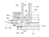
(3)本実施形態のガス供給ノズル導入部の構成
続いて、本実施形態にかかるガス供給ノズル230の導入部の構成について、図3〜5を用いて説明する。なお、本構成にかかるマニホールド209は、石英(SiO2)や炭化珪素(SiC)等の耐熱性を有する非金属により構成されている。
(3) Configuration of Gas Supply Nozzle Introducing Section of the Present Embodiment Next, the configuration of the introducing section of the
マニホールド209は、上端および下端が開口した円筒形状として形成されている。なお、図3には図示していないが、マニホールド209の上端部は、Oリング220aを介してアウターチューブ205の下端部を支持するとともに、インナーチューブ204の下端部を支持している。また、マニホールド209の下端部は、シールキャップ219上に当接されるように構成されている。また、マニホールド209は、緩衝性を有するシート部材である109bを介して、ステンレス鋼(SUS)やニッケル合金等の金属からなるインレットアダプタサポート109aにより下方から支持されている。
The manifold 209 is formed in a cylindrical shape with an upper end and a lower end opened. Although not shown in FIG. 3, the upper end portion of the manifold 209 supports the lower end portion of the
マニホールド209の側壁には、ガス供給ノズル230を挿入するための開口部(貫通
穴)209aが、少なくとも1つ設けられている。そして、マニホールド209の開口部209aには、ガス供給ノズル230を保持する金属製の継手部103が、マニホールド209の外側からOリング105を介して当接されるように構成されている。
The side wall of the manifold 209 is provided with at least one opening (through hole) 209 a for inserting the
継手部103は、押付け部としてのスプリング107によりマニホールド209の外周側に押付けられ、マニホールド209に設けられた開口部209aの外周を気密に塞ぐように構成されている。
The
具体的には、継手部103の外周に、マニホールド209側が高く構成された段差103a、あるいは突起が設けられている。そして、押付け部としてのスプリング107が、マニホールド209とは反対側(ガス供給管232側)から継手部103の外周を囲うように配置され、その端部が上述の段差103aあるいは突起に係止されている。スプリング107の外周(スプリング107におけるマニホールド209とは反対側の端部)は、支持材としてのネジ106により支持されている。支持材としてのネジ106は、例えばインレットアダプタサポート109aにより支持されて、マニホールド209側あるいはガス供給管232側に水平移動が可能なように構成されている。そして、ネジ106をマニホールド209側に移動させ、スプリング107の反発力を継手部103に伝えることにより、継手部103をマニホールド209の外側に押付けることが可能なように構成されている。つまり、ネジ106は、マニホールド209とは反対側(ガス供給管232側)で、スプリング107の反力を支持するように構成されている。
Specifically, a
このように、スプリング107の反発力を用いて継手部103をマニホールド209の外周側に押付けることで、マニホールド209の厚さや継手部103の長さ等の加工精度に誤差があったとしても、スプリング107が変形することによってマニホールド209に所定以上の力が加わることを防止することが出来る。また、反応容器内の真空引きや反応容器内の加熱によりマニホールド209の位置が変位しても、スプリング107が変形することによってマニホールド209に所定以上の力が加わることを防止することが出来るとともに、継手部103と開口部209aとの軸心がずれることを抑制できる。なお、継手部103の外周には、ネジ106の脱落を防止するための止め輪112を設けることが好ましい。
Thus, even if there is an error in processing accuracy such as the thickness of the manifold 209 and the length of the
ガス供給ノズル230は、マニホールド209に設けられた開口部に挿入されるとともに、上述の継手部103によって保持される。なお、なお、ガス供給ノズル230と継手部103との間は密着しており、反応容器内は気密に保たれるように構成されている。
The
また、上述したように、ガス供給ノズル230の上流側端部は、Oリング119を介してガス供給管232に気密に接続されている。具体的には、ガス供給管232の下流側端部はスリーブ232aとナット232bとを有しており、ナット232bを継手部303の外周部に固定することにより、ガス供給管232とガス供給ノズル230とが気密に接続されるよう構成されている。
As described above, the upstream end of the
上記においては、押付け部としてのスプリング107を、継手部103に対してガス供給管232側に設置していたが、本発明は上述の実施形態は上述の構成に限定されない。例えば、スプリング107を継手部103に対してマニホールド209側に設置し、スプリング107の収縮力によって継手部103をマニホールド209の外周側に押付けてもよい。また、スプリング107の端部を継手部103の外周に設けた段差や突起に係止していたが、スプリング107の端部を継手部103の外周に溶接することとしてもよい。また、押付け部としては、コイルバネに限らず、例えば板バネなどの他の弾性体を用いてもよい。
In the above description, the
なお、図4に示すように、継手部103とマニホールド209との間に設けられるOリング105の取り付けは、例えば、継手部103の先端面(マニホールド209に対向する面)にリング状のOリング取付溝を設け、このOリング取付溝にOリング105を嵌め込むことによって行うことが好ましい。そして、Oリング105の脱落を抑制するため、Oリング取付溝の内側(継手部103の外周側)をテーパ加工することが好ましい。
As shown in FIG. 4, the O-
また、図4に示すように、継手部103の先端面であってOリング105の外側には、Oリング105の外周を囲うように、リング状の緩衝部材としてのクッションリング104を設けることが好ましい。継手部103がマニホールド209側に押し付けられてOリング105が潰れたときに、金属製の継手部103が石英製のマニホールド209に直接接触することを回避するためである。クッションリング104の取り付けは、例えば、継手部103の先端面であってOリング取付溝の外側にリング状のクッションリング取付溝を設け、このクッションリング取付溝にクッションリング104を嵌め込むことによって行うことが出来る。この際、クッションリング104の脱落を防ぐため、クッションリング104の内側(内壁)、及びクッションリング取付溝の内側(継手部103の外周側)を、図4に示すようにテーパ加工することが好ましい。なお、クッションリング104は、例えば、テフロン(登録商標)等の耐熱性の高い樹脂を好適に用いることが好ましい。
Further, as shown in FIG. 4, a
また、図4に示すように、クッションリング104を設ける際には、マニホールド209の外周側に、開口部(貫通穴)209aと同心円状の座繰り加工を行って座繰り部209fを設けることが好ましい。座繰り部209fの内径とクッションリング104の外径とを一致させることにより、これらの相対的な位置合わせ(例えば軸心合わせ等)を容易に行うことが可能になるからである。これにより、ガス供給ノズル230の取り付け角度や位置を正確に行うことが可能となり、ガス供給ノズル230とマニホールド209とが接触して破損することを回避することが可能となる。
As shown in FIG. 4, when the
また、図5に示すように、継手部103には、継手部103の回転を抑制する抑制部としてのピン111が設けられていることが好ましい。具体的には、抑制部としてのピン111を、継手部103の下側から突出するように設けるとともに、継手部103と対向するインレットアダプタサポート109aに、ピン111に対応するガイド溝109cを設けることが好ましい。これにより、ネジ106を回転させたときに、ピン111がガイド溝109cの内壁に干渉して、継手部103が回転してしまうことを抑制することが可能となり、Oリング105の磨耗やガス供給ノズル230の破損等を回避することが可能になる。
Further, as shown in FIG. 5, the
(4)基板処理工程
続いて、本実施形態にかかる基板処理装置により実施される基板処理工程について説明する。
(4) Substrate Processing Step Next, the substrate processing step performed by the substrate processing apparatus according to the present embodiment will be described.
まず、プロセスチューブ203内から搬出されているボート217に、複数枚の基板200を装填(ウェハチャージ)する。これにより、ボート217に、薄膜が形成されるべき複数枚、例えば100枚、直径300mmの基板200が収容される。基板の装填が終了すると、複数枚の基板200を保持したボート217を、ボートエレベータ115によって持ち上げて、図6に示すように、処理室201内に搬入(ボートローディング)する(反応容器内に基板を搬入する工程)。この状態で、マニホールド209の下端は、Oリング220bを介してシールキャップ219によりシールされた状態となる。
First, a plurality of
反応容器内に基板を搬入する工程が終了すると、処理室201内が所望の圧力(真空度)となるように真空排気装置246によって真空排気する。これにより、処理室201内の雰囲気を排気系231を介して排出する。この際、処理室201内の圧力を、圧力セン
サ245で測定する。この測定した圧力に基づいて、メインバルブ242の開度をフィードバック制御する。また、処理室201内が所望の温度となるようにヒータ206によって処理室201内を加熱する。そして、ヒータ206への通電具合は、温度センサ263が検出した温度情報に基づき、処理室201内が所望の温度分布となるようにフィードバック制御する。続いて、回転機構254によりボート217を回転させることで、基板200を回転させる。
When the step of carrying the substrate into the reaction vessel is completed, the
次いで、反応容器内に処理ガスを供給して、基板上への成膜処理を実行する。すなわち、図示しない処理ガス供給源から供給され、MFC241にて所望の流量となるように制御されたガスをガス供給体としてのガス供給管232から供給して、ガス供給ノズル230を介して処理室201内へと導入する。導入されたガスは、処理室201内を上昇し、インナーチューブ204の上端開口から筒状空間250内に流出して、排気系231から排気される。処理ガスは、処理室201内を通過する際に基板200の表面と接触し、この際に熱CVD反応によって基板200の表面上に薄膜が堆積(デポジション)される。
Next, a processing gas is supplied into the reaction vessel, and a film forming process on the substrate is performed. That is, a gas supplied from a processing gas supply source (not shown) and controlled to have a desired flow rate by the
成膜処理が終了したら、アフタパージ処理を実行する。すなわち、ガス供給管232からガス供給ノズル230を介して処理室201内に不活性ガスを供給する。また、このとき、真空排気装置246によって真空排気処理を実行する。その結果、処理室201内の雰囲気が不活性ガスにより浄化される。
After the film forming process is completed, an after purge process is executed. That is, an inert gas is supplied from the
アフタパージ処理が終了したら、大気戻し処理を実行する。すなわち、真空排気処理を停止して、不活性ガスの供給処理だけを実行する。その結果、処理室201内の圧力が常圧に復帰する。
When the after purge process is completed, the atmosphere return process is executed. That is, the evacuation process is stopped and only the inert gas supply process is executed. As a result, the pressure in the
なお、少なくとも上述の成膜処理、アフタパージ処理、及び大気戻し処理は、ガス供給ノズル230を保持する継手部103を、押付け部としてのスプリング107により反応容器の外周に押し付けて、開口部203aを気密に塞いだ状態で実行する。すなわち、少なくとも処理室201内にガスを供給する間は、支持材としてのネジ106をマニホールド209側に移動させ、継手部103をマニホールド209の外周に押付けて、開口部203aの周囲を継手部103により気密に塞いでおく。
Note that at least the film forming process, the after purge process, and the atmosphere returning process described above are performed by pressing the
大気戻し処理が終了したら、ボートアンロード処理を実行する。すなわち、ボートエレベータ115によりシールキャップ219を下降させ、マニホールド209の下端を開口させるとともに、成膜処理の済んだ基板200を、ボート217に保持させた状態でマニホールド209の下端からプロセスチューブ203の外部に搬出(ボートアンローディング)する(基板を処理室より搬出する工程)。その後、成膜処理の済んだ基板200を、ボート217より回収して(ウェハディスチャージ)、1バッチ目の処理を終了する。以下、同様に、2バッチ目以降も処理対象の基板200に対して上述の処理を実行する。
When the atmosphere return process is completed, the boat unload process is executed. That is, the
(5)本実施形態にかかる効果
本実施形態によれば、以下に示す1つ又は複数の効果を奏する。
(5) Effects according to the present embodiment According to the present embodiment, the following one or more effects are achieved.
本実施形態にかかる成膜処理、アフタパージ処理、及び大気戻し処理は、ガス供給ノズル230を保持する継手部103を、押付け部としてのスプリング107により反応容器の外周に押し付けて、開口部203aを気密に塞いだ状態で実行する。従って、反応容器内の気密を維持したまま、これらの処理を実施することが出来る。
In the film forming process, the after purge process, and the atmosphere returning process according to the present embodiment, the
また、マニホールド209が石英等の非金属により構成されているため、反応容器内の金属の露出面が少ない。そのため、成膜処理などの基板処理を行う際に、基板が金属汚染される可能性を低減させることが可能となる。 Further, since the manifold 209 is made of non-metal such as quartz, the exposed surface of the metal in the reaction vessel is small. Therefore, when performing substrate processing such as film formation processing, it is possible to reduce the possibility of metal contamination of the substrate.
また、石英製のマニホールド209の外周からは、マニホールド209と一体成形された石英製のパイプ209bが突出していない。そのため、部品の破損が発生しにくい。
Further, a
また、石英製のマニホールド209の形状を単純化させることが可能となり、基板処理装置の製造コストを低減させることが出来る。
In addition, the shape of the
また、スプリング107の反発力により継手部103をマニホールド209の外周側に押付けることで、マニホールド209の厚さや継手部103の長さの寸法に誤差があったとしても、スプリング107が変形することによってマニホールド209等に対し所定以上の力が加わることを防止することが出来る。そのため、マニホールド209の破損を防ぐことが出来るとともに、マニホールド209や継手部103の加工精度を下げることが可能となり、基板処理装置の製造コストを低減させることが出来る。
Further, by pressing the
また、反応容器内の真空引きや反応容器内の加熱によりマニホールド209の位置や厚さが変位しても、スプリング107が変形することによってマニホールド209等に所定以上の力が加わることを防止することが出来る。そのため、マニホールド209の破損を防ぐことが出来る。さらには、継手部103と開口部209aとの軸心がずれることを抑制することが可能となり、ガス供給ノズル230を安定して保持することが出来るとともに、マニホールド209とガス供給ノズル230とが接触してこれらが破損することを回避することが出来る。
Further, even if the position and thickness of the manifold 209 are displaced due to evacuation in the reaction vessel or heating in the reaction vessel, the
また、継手部103には、継手部103の回転を抑制する抑制部としてのピン111が設けられているとともに、継手部103の下側に対向するインレットアダプタサポート109aに、ピン111に対応するガイド溝109cが設けられている。そのため、ネジ106を回転させたときに、継手部103が回転してしまうことを抑制することが出来る。その結果、Oリング105の磨耗を抑制することができ、ガス供給ノズル230の破損等を抑制することが出来る。
In addition, the
また、継手部103とマニホールド209との間に設けられるOリング105の取り付けは、例えば、継手部103の先端面(マニホールド209に対向する面)にリング状のOリング取付溝を設け、このOリング取付溝にOリング105を嵌め込むことによって行われている。さらには、Oリング取付溝の内側(継手部103の外周側)がテーパ加工されている。そのため、基板処理装置の組み立てやメンテナンスを行う際に、Oリング105が脱落することを抑制できる。
The O-
また、継手部103の先端面であってOリング105の外側には、Oリング105の外周を囲うように、リング状の緩衝部材としてのクッションリング104を設けられている。そのため、継手部103がマニホールド209側に押し付けられてOリング105が潰れたときに、金属製の継手部103が石英製のマニホールド209に直接接触することを抑制し、金属部品と接触することによるマニホールド209の破損を抑制することが可能になる。
Further, a
また、クッションリング104は、継手部103の先端面であってOリング取付溝の外側に設けられたクッションリング取付溝に嵌め込まれている。そして、クッションリング104の内側、及びクッションリング取付溝の内側(継手部103の外周側)はテーパ加工されている。そのため、基板処理装置の組み立てやメンテナンスを行う際に、クッションリング104の脱落を抑制することが出来る。
Further, the
また、マニホールド209の外周側に、開口部(貫通穴)209aと同心円状に座繰り
部209fが設けられているとともに、座繰り部209fの内径とクッションリング104の外径とが一致している。そのため、基板処理装置の組み立てやメンテナンスを行う際に、開口部209aと継手部103との相対的な位置合わせ(例えば軸心合わせ等)を容易に行うことが可能となる。これにより、ガス供給ノズル230の取り付け角度や位置を正確に行うことが可能となり、ガス供給ノズル230とマニホールド209とが接触して破損することを回避することが可能となる。
Further, a
<他の実施態様>
以下に、本発明の好ましい態様について付記する。
<Other embodiments>
Hereinafter, preferred embodiments of the present invention will be additionally described.
本発明の第1の態様によれば、ガス供給ノズルが挿入される開口部が設けられた反応容器と、該反応容器外にて前記ガス供給ノズルに接続され前記反応容器内にガスを供給するガス供給体と、該ガス供給体と前記反応容器との間に設けられ前記ガス供給ノズルを保持する継手部と、該継手部が前記開口部を気密に塞ぐように前記継手部を前記反応容器側に押し付ける押付け部と、を備える基板処理装置が提供される。 According to the first aspect of the present invention, a reaction vessel provided with an opening into which a gas supply nozzle is inserted, and gas is supplied into the reaction vessel connected to the gas supply nozzle outside the reaction vessel. A gas supply body, a joint portion provided between the gas supply body and the reaction vessel, and holding the gas supply nozzle; and the joint portion that seals the opening in an airtight manner. There is provided a substrate processing apparatus comprising: a pressing unit that presses against the side.
本発明の第2の態様によれば、ガス供給ノズルが挿入される開口部が設けられた反応容器内に基板を搬入する工程と、前記ガス供給ノズルを保持する継手部を押付け部により前記反応容器の外周に押し付けて前記開口部を気密に塞いだ状態で、前記反応容器外にて前記ガス供給ノズルに接続されたガス供給体から前記反応容器内にガスを供給して基板を処理する工程と、前記反応容器内から基板を搬出する工程と、を有する半導体装置の製造方法が提供される。 According to the second aspect of the present invention, the step of carrying the substrate into the reaction container provided with the opening into which the gas supply nozzle is inserted, and the reaction part that holds the gas supply nozzle by the pressing part are used for the reaction. A process of processing the substrate by supplying gas into the reaction container from a gas supply body connected to the gas supply nozzle outside the reaction container in a state in which the opening is hermetically closed by pressing against the outer periphery of the container And a step of unloading the substrate from the reaction vessel.
本発明の第3の態様によれば、反応容器と、該反応容器内にガスを供給するよう接続されるガス供給体と、該ガス供給体と前記反応容器との間に設けられ、少なくとも前記ガス供給体と前記反応容器とを連通させるガス供給ノズルを保持する継手部と、該継手部を前記反応容器側に反発力により押付ける押付け部と、を備える基板処理装置が提供される。 According to the third aspect of the present invention, a reaction vessel, a gas supply connected to supply gas into the reaction vessel, and provided between the gas supply and the reaction vessel, at least the There is provided a substrate processing apparatus comprising: a joint portion that holds a gas supply nozzle that communicates a gas supply body and the reaction vessel; and a pressing portion that presses the joint portion against the reaction vessel side by a repulsive force.
本発明の第4の態様によれば、反応容器内に基板を搬入する工程と、ガス供給体と前記反応容器との間に設けられ、少なくとも前記ガス供給体と前記反応容器とを連通させるガス供給ノズルを保持する継手部を押付け部により前記反応容器側に押付けた状態で、前記ガス供給体から前記ガス供給ノズルを経由し前記反応容器内にガスを供給する工程と、前記反応容器内で基板を処理する工程と、前記反応容器内から基板を搬出する工程と、を有する半導体装置の製造方法が提供される。 According to the fourth aspect of the present invention, a gas is provided between the step of carrying the substrate into the reaction vessel and the gas supply body and the reaction vessel, and communicates at least the gas supply body and the reaction vessel. A step of supplying gas from the gas supply body through the gas supply nozzle into the reaction vessel in a state where the joint holding the supply nozzle is pressed against the reaction vessel by the pressing portion; There is provided a method for manufacturing a semiconductor device, comprising a step of processing a substrate and a step of unloading the substrate from the reaction vessel.
本発明の第5の態様によれば、反応管と、該反応管を支持するマニホールドと、該マニホールドに継手部を介して接続され、該反応容器内にガスを供給するガス供給体と、該継手部外周に設けられ、該継手部を前記マニホールド側に反発力あるいは収縮力により押付ける押付け部と、該押付け部の外周に設けられ、該押付け部を支持し、前記マニホールド側とは反対側で前記押付け部の反力を支持する支持材と、を備える基板処理装置が提供される。 According to the fifth aspect of the present invention, a reaction tube, a manifold that supports the reaction tube, a gas supply body that is connected to the manifold via a joint and supplies gas into the reaction vessel, and Provided on the outer periphery of the joint, pressing the joint against the manifold side by repulsive force or contraction force, and provided on the outer periphery of the pressing part, supporting the pressing part, opposite to the manifold side And a support material that supports the reaction force of the pressing portion.
本発明の第6の態様によれば、前記マニホールドは非金属材により構成される第5の態様に記載の基板処理装置が提供される。 According to a sixth aspect of the present invention, there is provided the substrate processing apparatus according to the fifth aspect, wherein the manifold is made of a non-metallic material.
本発明の第7の態様によれば、前記継手部は、前記反応管内にガスを供給するガス供給ノズルを保持し、少なくとも前記押付け部の反発力あるいは収縮力により、前記マニホールドと前記継手部との間を真空シール可能なように設けられている第5又は6の態様に記載の基板処理装置が提供される。 According to the seventh aspect of the present invention, the joint portion holds a gas supply nozzle that supplies gas into the reaction tube, and at least the repulsion force or contraction force of the pressing portion causes the manifold and the joint portion to The substrate processing apparatus as described in the 5th or 6th aspect provided so that a space | interval can be vacuum-sealed is provided.
本発明の第8の態様によれば、前記継手部は、金属材により構成されており、前記マニホールドとは非接触となるように前記マニホールドと前記継手部との間に設けられるOリングの外側に緩衝部材を介在させている第6の態様に記載の基板処理装置が提供される。 According to an eighth aspect of the present invention, the joint portion is made of a metal material, and an outer side of an O-ring provided between the manifold and the joint portion so as not to contact the manifold. A substrate processing apparatus according to a sixth aspect in which a buffer member is interposed is provided.
本発明の第9の態様によれば、前記緩衝部材は樹脂によりリング状に形成されており、該リング外径と前記マニホールドに設けられた座繰り部内径とで軸心合わせが可能な第8の態様に記載の基板処理装置が提供される。 According to a ninth aspect of the present invention, the buffer member is formed in a ring shape from a resin, and an eighth center capable of axial alignment with the outer diameter of the ring and the inner diameter of the countersunk portion provided in the manifold. The substrate processing apparatus according to the aspect is provided.
本発明の第10の態様によれば、前記継手部は、該継手部の回転を抑制する抑制部を備える第7の態様に記載の基板処理装置が提供される。 According to a tenth aspect of the present invention, there is provided the substrate processing apparatus according to the seventh aspect, wherein the joint portion includes a suppressing portion that suppresses rotation of the joint portion.
本発明の第11の態様によれば、前記押付け部には、スプリング材が設けられている第1,3,5のいずれかの態様に記載の基板処理装置が提供される。 According to an eleventh aspect of the present invention, there is provided the substrate processing apparatus according to any one of the first, third, and fifth aspects, wherein the pressing portion is provided with a spring material.
本発明の第12の態様によれば、前記スプリング材は、圧縮バネもしくは板バネである第11の態様に記載の基板処理装置が提供される。 According to a twelfth aspect of the present invention, there is provided the substrate processing apparatus according to the eleventh aspect, wherein the spring material is a compression spring or a leaf spring.
本発明の第13の態様によれば、前記継手部にOリング取付溝が形成されており、該取付溝の内側がテーパ加工されている第8の態様に記載の基板処理装置が提供される。 According to a thirteenth aspect of the present invention, there is provided the substrate processing apparatus according to the eighth aspect, wherein an O-ring attachment groove is formed in the joint portion, and an inner side of the attachment groove is tapered. .
本発明の第14の態様によれば、前記緩衝部材の内側と前記継手部の外側とがそれぞれテーパ加工されており、該テーパ部を用いて前記緩衝部材を前記継手部に嵌め込むように形成されている第9の態様に記載の基板処理装置が提供される。 According to the fourteenth aspect of the present invention, the inner side of the buffer member and the outer side of the joint part are each tapered so that the buffer member is fitted into the joint part using the taper part. A substrate processing apparatus according to the ninth aspect is provided.
103 継手部
106 ネジ(支持材)
107 スプリング(押付け部)
109a インレットアダプタサポート
109c ガイド溝
111 ピン(抑制部)
200 基板
203 プロセスチューブ(反応管)
203a 開口部
209 マニホールド
209a 開口部
209f 座繰り部
230 ガス供給ノズル
232 ガス供給管(ガス供給体)
103
107 Spring (Pressing part)
109a
200
Claims (3)
該反応容器外にて前記ガス供給ノズルに接続され前記反応容器内にガスを供給するガス供給体と、
該ガス供給体と前記反応容器との間に設けられ前記ガス供給ノズルを保持する継手部と、
該継手部が前記開口部を気密に塞ぐように前記継手部を前記反応容器側に押し付ける弾性体で構成された押付け部と、
前記押付け部の端部に設けられ、水平移動することによって前記押付け部からの反発力を支持する支持部と、
を備える基板処理装置。 A reaction vessel provided with an opening into which the gas supply nozzle is inserted and made of a non-metal;
A gas supply body connected to the gas supply nozzle outside the reaction vessel and supplying gas into the reaction vessel;
A joint provided between the gas supply body and the reaction vessel and holding the gas supply nozzle;
A pressing portion composed of an elastic body that presses the joint portion against the reaction vessel side so that the joint portion seals the opening hermetically;
A support portion provided at an end of the pressing portion and supporting a repulsive force from the pressing portion by horizontally moving;
A substrate processing apparatus comprising:
弾性体で構成された押付け部が、前記押付け部の端部に設けられ、前記押付け部からの反発力を支持する支持部が水平移動することによって前記ガス供給ノズルを保持する継手部を前記反応容器の外周に押し付けて前記開口部を気密に塞いだ状態で、前記反応容器外にて前記ガス供給ノズルに接続されたガス供給体から前記反応容器内にガスを供給して基板を処理する工程と、
前記反応容器内から基板を搬出する工程と、
を有する半導体装置の製造方法。 A step of carrying the substrate into a reaction vessel that is provided with an opening into which the gas supply nozzle is inserted and is made of a non-metal;
A pressing portion made of an elastic body is provided at an end portion of the pressing portion, and a support portion that supports a repulsive force from the pressing portion moves horizontally so that a joint portion that holds the gas supply nozzle is reacted with the reaction portion. A process of processing the substrate by supplying gas into the reaction container from a gas supply body connected to the gas supply nozzle outside the reaction container in a state in which the opening is airtightly closed by pressing the outer periphery of the container When,
Unloading the substrate from the reaction vessel;
A method for manufacturing a semiconductor device comprising:
Priority Applications (1)
| Application Number | Priority Date | Filing Date | Title |
|---|---|---|---|
| JP2007266160A JP5242984B2 (en) | 2007-10-12 | 2007-10-12 | Substrate processing apparatus and semiconductor device manufacturing method |
Applications Claiming Priority (1)
| Application Number | Priority Date | Filing Date | Title |
|---|---|---|---|
| JP2007266160A JP5242984B2 (en) | 2007-10-12 | 2007-10-12 | Substrate processing apparatus and semiconductor device manufacturing method |
Publications (2)
| Publication Number | Publication Date |
|---|---|
| JP2009094426A JP2009094426A (en) | 2009-04-30 |
| JP5242984B2 true JP5242984B2 (en) | 2013-07-24 |
Family
ID=40666079
Family Applications (1)
| Application Number | Title | Priority Date | Filing Date |
|---|---|---|---|
| JP2007266160A Active JP5242984B2 (en) | 2007-10-12 | 2007-10-12 | Substrate processing apparatus and semiconductor device manufacturing method |
Country Status (1)
| Country | Link |
|---|---|
| JP (1) | JP5242984B2 (en) |
Families Citing this family (2)
| Publication number | Priority date | Publication date | Assignee | Title |
|---|---|---|---|---|
| JP6345497B2 (en) * | 2014-06-16 | 2018-06-20 | 古河機械金属株式会社 | Gas distribution pipe fitting and vapor phase growth apparatus |
| CN218299750U (en) * | 2019-03-20 | 2023-01-13 | 株式会社国际电气 | Gas supply unit and substrate processing apparatus |
Family Cites Families (5)
| Publication number | Priority date | Publication date | Assignee | Title |
|---|---|---|---|---|
| JP3172756B2 (en) * | 1993-01-20 | 2001-06-04 | 東京エレクトロン株式会社 | Processing equipment |
| JP3436955B2 (en) * | 1993-10-18 | 2003-08-18 | 東京エレクトロン株式会社 | Heat treatment equipment |
| JP4282912B2 (en) * | 2001-03-29 | 2009-06-24 | 東京エレクトロン株式会社 | Vertical heat treatment equipment |
| JP2007027426A (en) * | 2005-07-15 | 2007-02-01 | Hitachi Kokusai Electric Inc | Substrate processing device |
| JP5036172B2 (en) * | 2005-11-21 | 2012-09-26 | 株式会社日立国際電気 | Substrate processing apparatus, substrate processing method, and semiconductor device manufacturing method |
-
2007
- 2007-10-12 JP JP2007266160A patent/JP5242984B2/en active Active
Also Published As
| Publication number | Publication date |
|---|---|
| JP2009094426A (en) | 2009-04-30 |
Similar Documents
| Publication | Publication Date | Title |
|---|---|---|
| US8529701B2 (en) | Substrate processing apparatus | |
| KR100932168B1 (en) | Method of manufacturing substrate processing apparatus and semiconductor device | |
| US8851886B2 (en) | Substrate processing apparatus and method of manufacturing semiconductor device | |
| TWI387666B (en) | Substrate processing apparatus and method of manufacturing semiconductor device | |
| KR100936554B1 (en) | Apparatus and method for semiconductor process | |
| US8591657B2 (en) | Substrate processing apparatus and method of manufacturing semiconductor device | |
| JP5242984B2 (en) | Substrate processing apparatus and semiconductor device manufacturing method | |
| KR20100012816A (en) | Substrate processing apparatus | |
| KR20170090967A (en) | Substrate processing apparatus, method of manufacturing semiconductor device and non-transitory computer-readable recording medium | |
| JP4652408B2 (en) | Substrate processing apparatus, reaction tube, substrate processing method, and semiconductor device manufacturing method | |
| JP5087283B2 (en) | Temperature control system, substrate processing apparatus, and semiconductor device manufacturing method | |
| JP2010056124A (en) | Substrate processing device and method for manufacturing semiconductor device | |
| JP7194805B2 (en) | Gas supply unit, substrate processing apparatus, and semiconductor device manufacturing method | |
| JPH0247266A (en) | Treating device | |
| JP4342765B2 (en) | Substrate processing equipment | |
| JP2012099723A (en) | Substrate processing apparatus | |
| JP2010245422A (en) | Semiconductor manufacturing device | |
| JP5060916B2 (en) | Substrate processing apparatus, semiconductor device manufacturing method, and substrate processing method | |
| JP2007324478A (en) | Substrate processing apparatus | |
| JP2010040919A (en) | Substrate processing apparatus | |
| KR20180050709A (en) | Substrate processing apparatus, joint part, and manufacturing method of semiconductor device | |
| JP2011198957A (en) | Substrate processing apparatus, substrate holder, and method of manufacturing semiconductor device | |
| JP2013016635A (en) | Substrate processing apparatus and semiconductor device manufacturing method | |
| JP2010093131A (en) | Substrate processing apparatus | |
| KR20230042552A (en) | Furnace opening structure, substrate processing apparatus and method of manufacturing semiconductor device |
Legal Events
| Date | Code | Title | Description |
|---|---|---|---|
| A621 | Written request for application examination |
Free format text: JAPANESE INTERMEDIATE CODE: A621 Effective date: 20101006 |
|
| A977 | Report on retrieval |
Free format text: JAPANESE INTERMEDIATE CODE: A971007 Effective date: 20110719 |
|
| A131 | Notification of reasons for refusal |
Free format text: JAPANESE INTERMEDIATE CODE: A131 Effective date: 20121024 |
|
| A521 | Request for written amendment filed |
Free format text: JAPANESE INTERMEDIATE CODE: A523 Effective date: 20121221 |
|
| A131 | Notification of reasons for refusal |
Free format text: JAPANESE INTERMEDIATE CODE: A131 Effective date: 20130116 |
|
| RD03 | Notification of appointment of power of attorney |
Free format text: JAPANESE INTERMEDIATE CODE: A7423 Effective date: 20130307 |
|
| A521 | Request for written amendment filed |
Free format text: JAPANESE INTERMEDIATE CODE: A523 Effective date: 20130308 |
|
| TRDD | Decision of grant or rejection written | ||
| A01 | Written decision to grant a patent or to grant a registration (utility model) |
Free format text: JAPANESE INTERMEDIATE CODE: A01 Effective date: 20130327 |
|
| A61 | First payment of annual fees (during grant procedure) |
Free format text: JAPANESE INTERMEDIATE CODE: A61 Effective date: 20130404 |
|
| FPAY | Renewal fee payment (event date is renewal date of database) |
Free format text: PAYMENT UNTIL: 20160412 Year of fee payment: 3 |
|
| R150 | Certificate of patent or registration of utility model |
Free format text: JAPANESE INTERMEDIATE CODE: R150 Ref document number: 5242984 Country of ref document: JP Free format text: JAPANESE INTERMEDIATE CODE: R150 |
|
| R250 | Receipt of annual fees |
Free format text: JAPANESE INTERMEDIATE CODE: R250 |
|
| R250 | Receipt of annual fees |
Free format text: JAPANESE INTERMEDIATE CODE: R250 |
|
| R250 | Receipt of annual fees |
Free format text: JAPANESE INTERMEDIATE CODE: R250 |
|
| S111 | Request for change of ownership or part of ownership |
Free format text: JAPANESE INTERMEDIATE CODE: R313111 |
|
| S531 | Written request for registration of change of domicile |
Free format text: JAPANESE INTERMEDIATE CODE: R313531 |
|
| R350 | Written notification of registration of transfer |
Free format text: JAPANESE INTERMEDIATE CODE: R350 |
|
| R250 | Receipt of annual fees |
Free format text: JAPANESE INTERMEDIATE CODE: R250 |
|
| R250 | Receipt of annual fees |
Free format text: JAPANESE INTERMEDIATE CODE: R250 |
|
| R250 | Receipt of annual fees |
Free format text: JAPANESE INTERMEDIATE CODE: R250 |
|
| R250 | Receipt of annual fees |
Free format text: JAPANESE INTERMEDIATE CODE: R250 |
|
| R250 | Receipt of annual fees |
Free format text: JAPANESE INTERMEDIATE CODE: R250 |
|
| R250 | Receipt of annual fees |
Free format text: JAPANESE INTERMEDIATE CODE: R250 |