JP5241663B2 - Solid electrolyte fuel cell stack, bundle and fuel cell - Google Patents
Solid electrolyte fuel cell stack, bundle and fuel cell Download PDFInfo
- Publication number
- JP5241663B2 JP5241663B2 JP2009211877A JP2009211877A JP5241663B2 JP 5241663 B2 JP5241663 B2 JP 5241663B2 JP 2009211877 A JP2009211877 A JP 2009211877A JP 2009211877 A JP2009211877 A JP 2009211877A JP 5241663 B2 JP5241663 B2 JP 5241663B2
- Authority
- JP
- Japan
- Prior art keywords
- fuel
- fuel cell
- cell stack
- fuel electrode
- electrode
- Prior art date
- Legal status (The legal status is an assumption and is not a legal conclusion. Google has not performed a legal analysis and makes no representation as to the accuracy of the status listed.)
- Expired - Fee Related
Links
Images


Classifications
-
- Y—GENERAL TAGGING OF NEW TECHNOLOGICAL DEVELOPMENTS; GENERAL TAGGING OF CROSS-SECTIONAL TECHNOLOGIES SPANNING OVER SEVERAL SECTIONS OF THE IPC; TECHNICAL SUBJECTS COVERED BY FORMER USPC CROSS-REFERENCE ART COLLECTIONS [XRACs] AND DIGESTS
- Y02—TECHNOLOGIES OR APPLICATIONS FOR MITIGATION OR ADAPTATION AGAINST CLIMATE CHANGE
- Y02E—REDUCTION OF GREENHOUSE GAS [GHG] EMISSIONS, RELATED TO ENERGY GENERATION, TRANSMISSION OR DISTRIBUTION
- Y02E60/00—Enabling technologies; Technologies with a potential or indirect contribution to GHG emissions mitigation
- Y02E60/30—Hydrogen technology
- Y02E60/50—Fuel cells
-
- Y—GENERAL TAGGING OF NEW TECHNOLOGICAL DEVELOPMENTS; GENERAL TAGGING OF CROSS-SECTIONAL TECHNOLOGIES SPANNING OVER SEVERAL SECTIONS OF THE IPC; TECHNICAL SUBJECTS COVERED BY FORMER USPC CROSS-REFERENCE ART COLLECTIONS [XRACs] AND DIGESTS
- Y02—TECHNOLOGIES OR APPLICATIONS FOR MITIGATION OR ADAPTATION AGAINST CLIMATE CHANGE
- Y02P—CLIMATE CHANGE MITIGATION TECHNOLOGIES IN THE PRODUCTION OR PROCESSING OF GOODS
- Y02P70/00—Climate change mitigation technologies in the production process for final industrial or consumer products
- Y02P70/50—Manufacturing or production processes characterised by the final manufactured product
Landscapes
- Inert Electrodes (AREA)
- Fuel Cell (AREA)
Description
本発明は、内部に燃料の流通部を有する支持体の表面に発電素子部(セル)を設けた固体電解質形の燃料電池セルスタック、バンドル及び燃料電池に関するものである。 The present invention, the power generation element to the surface of the support having the internal fuel flow part provided therein (cell) solid oxide fuel cell stack having a, but about the bundle and fuel cells.
次世代エネルギーとして、近年、燃料電池が種々提案されている。このような燃料電池には、固体高分子形、リン酸形、溶融炭酸塩形、固体電解質形など、各種のものが知られているが、中でも固体電解質形燃料電池(SOFC;Solid Oxide Fuel Cell)は、作動温度が800〜1000℃と高いものの、発電効率が高く、また排熱利用ができるなどの利点を有しており、その研究開発が推し進められている。 In recent years, various fuel cells have been proposed as next-generation energy. Various types of fuel cells such as solid polymer type, phosphoric acid type, molten carbonate type, and solid electrolyte type are known. Among them, a solid oxide fuel cell (SOFC) is known. ) Has a high operating temperature of 800 to 1000 ° C., but has advantages such as high power generation efficiency and the ability to use exhaust heat, and its research and development is being promoted.
固体電解質形燃料電池は、燃料電池セルスタックを複数有し、これらの燃料電池セルスタックを互いに電気的に接続してバンドルとし、このバンドルを収納容器内に収容したものである。燃料電池セルスタックにおいては、その燃料電池セルスタックに発電素子部をどのように配置するかによって、いわゆる「横縞形」のタイプが知られている。
この横縞形の燃料電池セルスタックは、発電素子部を、セルスタックの長手方向に沿って複数個配置し、それらを直列に接続したものである。発電素子部は例えば1つあたり0.7Vの起電力しか得られないが、複数直列に接続することで、1セルスタック当たり相当の起電力が得られる。
The solid oxide fuel cell has a plurality of fuel cell stacks, and these fuel cell stacks are electrically connected to each other to form a bundle, and the bundle is accommodated in a storage container. In the fuel cell stack, a so-called “horizontal stripe” type is known depending on how the power generation element portion is arranged in the fuel cell stack.
In this horizontal stripe fuel cell stack, a plurality of power generating element portions are arranged along the longitudinal direction of the cell stack and connected in series. For example, only one electromotive force of 0.7 V can be obtained for each power generating element portion, but by connecting a plurality of power generating elements in series, a considerable electromotive force can be obtained per cell stack.
横縞形の燃料電池セルスタックは、多孔質絶縁体である支持体の表面に、発電素子部を長手方向に所定間隔をおいて複数配置している。それぞれの発電素子部は、燃料極、固体電解質及び空気極を順次積層した層構造となっている。互いに隣り合う発電素子部は、それぞれインターコネクタにより直列に接続されている。すなわち、一方の発電素子部の燃料極と他方の発電素子部の空気極とが、インターコネクタにより接続されている。そして、支持体の内部には燃料ガス流路が形成されている。 In the horizontally striped fuel cell stack, a plurality of power generating element portions are arranged at predetermined intervals in the longitudinal direction on the surface of a support that is a porous insulator. Each power generating element portion has a layer structure in which a fuel electrode, a solid electrolyte, and an air electrode are sequentially stacked. The power generating element portions adjacent to each other are connected in series by an interconnector. That is, the fuel electrode of one power generation element part and the air electrode of the other power generation element part are connected by the interconnector. A fuel gas flow path is formed inside the support.
前記構造の横縞形の燃料電池セルスタックの発電原理は、次のとおりである。
固体電解質の酸素イオン伝導性は600℃程度から高くなるため、600℃以上の温度域で、空気極に酸素を含むガスを、燃料極に水素を含むガスを各々供給することで、空気極と燃料極間の酸素濃度差が発生する。
空気極から固体電解質を通じて燃料極へ移動した酸素イオンは、燃料極で水素イオンと結合して水となる。このとき、空気極では、下記式(1)の電極反応を生じ、燃料極では、下記式(2)の電極反応を生じる。これにより電子の移動が起こり、発電する。
The power generation principle of the horizontal stripe fuel cell stack having the above structure is as follows.
Since the oxygen ion conductivity of the solid electrolyte increases from about 600 ° C., by supplying a gas containing oxygen to the air electrode and a gas containing hydrogen to the fuel electrode in a temperature range of 600 ° C. or higher, A difference in oxygen concentration occurs between the fuel electrodes.
Oxygen ions that have moved from the air electrode to the fuel electrode through the solid electrolyte are combined with hydrogen ions at the fuel electrode to become water. At this time, an electrode reaction of the following formula (1) occurs at the air electrode, and an electrode reaction of the following formula (2) occurs at the fuel electrode. As a result, electrons move and generate electricity.
空気極: 1/2O2+2e-→ O2-(固体電解質) …(1)
燃料極: O2-(固体電解質)+H2→ H2O+2e- …(2)
横縞形の燃料電池セルスタックでは、以上の反応を起こす発電素子部が、支持体表面に、長手方向に複数形成され且つ互いに直列に接続されているために、少ないセルスタック数で高い電圧を得られるという利点がある。
Air electrode: 1 / 2O 2 + 2e − → O 2− (solid electrolyte) (1)
Fuel electrode: O 2− (solid electrolyte) + H 2 → H 2 O + 2e − (2)
In the horizontal stripe fuel cell stack, a plurality of power generating element parts that cause the above reaction are formed in the longitudinal direction on the support surface and connected in series with each other, so that a high voltage can be obtained with a small number of cell stacks. There is an advantage that
従来、隣り合う発電素子部同士を接続するインターコネクタ16は、図6に示すように、絶縁性の支持体12の上に直接形成され、燃料極13に接続される部分16aと、折れ曲がって空気極15に接続する部分16bとを備えていた。
しかし、このインターコネクタ16の形状では、インターコネクタ16を長手方向に流れる電流のパスが長くなり、その分、燃料電池セルスタックの内部抵抗が大きくなり、燃料電池から発電電力を効率よく取り出せなくなる。
Conventionally, as shown in FIG. 6, the
However, with this shape of the
本発明は、燃料極から流れる電流経路を短くすることによって、発電素子部の間に介在する抵抗を減少させ、発電効率を向上させることのできる固体電解質形の燃料電池セルスタック、バンドル及び燃料電池を提供することを目的とする。 The present invention shortens a current path flowing from a fuel electrode, thereby reducing a resistance interposed between power generation element portions and improving a power generation efficiency, and a solid electrolyte fuel cell stack, a bundle, and a fuel cell The purpose is to provide a pond .
本発明の燃料電池セルスタックは、単一若しくは複数の燃料ガス流路が長手方向に形成された柱状の電気絶縁性の支持体の表面に、燃料極、固体電解質及び空気極をこの順に積層してなる発電素子部を長手方向に所定間隔をおいて複数個設け、該複数の発電素子部をインターコネクタを介して直列に接続してなる燃料電池セルスタックであって、前記インターコネクタが、前記発電素子部の前記燃料極の上に層状に形成されているとともに、前記固体電解質が前記インターコネクタの上面における前記支持体の長手方向の両端部を被覆した状態で前記燃料極の上に形成されており、前記インターコネクタの前記固体電解質で被覆されていない露出した部分と、隣り合う前記発電素子部の前記空気極との間を接続する発電素子接続部材がさらに設けられ、燃料極が、固体電解質側の活性燃料極と支持体側の集電燃料極とを具備して形成されており、活性燃料極が、Ni若しくはNi酸化物と、希土類元素が固溶しているZrO 2 との混合体からなり、集電燃料極が、Ni若しくはNi酸化物と、希土類元素酸化物との混合体からなり、インターコネクタが、活性燃料極の上に形成されている構造であることを特徴とする。 Fuel cell stack of the present invention, laminated on the surface of a single or a plurality of columnar fuel gas channel is formed in the long side direction of the electrically insulating support, a fuel electrode, a solid electrolyte and an air electrode in this order A plurality of power generation element portions are provided at predetermined intervals in the longitudinal direction, and the plurality of power generation element portions are connected in series via an interconnector, wherein the interconnector includes: It is formed in layers on the fuel electrode of the power generation element portion, and the solid electrolyte is formed on the fuel electrode in a state where both ends of the support in the longitudinal direction are covered on the upper surface of the interconnector. And a power generation element connection member that connects between the exposed portion of the interconnector that is not covered with the solid electrolyte and the air electrode of the adjacent power generation element portion. Vignetting, the fuel electrode, the solid electrolyte and electrolyte side of the active fuel electrode is formed by and a current collecting fuel electrode on the support side, the active fuel electrode, a Ni or Ni oxide, rare earth element dissolved and are made of a mixture of ZrO 2, the current collecting fuel electrode, a Ni or Ni oxide, consist mixture of rare earth oxide, interconnector is formed on the active anode structure It is characterized by being.
この構成であれば、一般に金属に比較して電気伝導度の低いセラミックスからなるインターコネクタを燃料極の上に層状に形成し、その上に発電素子接続部材を接続しているので、インターコネクタを長手方向に流れる電流のパスがなくなり、インターコネクタによる抵抗が減少する。
また、燃料極の上に形成される固体電解質は、当該インターコネクタの長手方向の両端部を被覆した状態で形成されているので、燃料電池セルスタックの内部と外部のガスシールも完全に行うことができる。
If it is this structure, since the interconnector which consists of ceramics with low electrical conductivity generally compared with a metal is formed in a layer form on a fuel electrode, and a power generation element connection member is connected on it, an interconnector is connected. The path of current flowing in the longitudinal direction is eliminated, and the resistance caused by the interconnector is reduced.
In addition, since the solid electrolyte formed on the fuel electrode is formed so as to cover both ends in the longitudinal direction of the interconnector, the gas sealing inside and outside the fuel cell stack should also be performed completely. Can do.
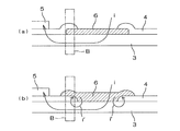
さらに、本発明において、固体電解質がインターコネクタの長手方向の両端部を被覆している効果を、図5を用いて説明する。
比較例として示す図5(b)では、インターコネクタ6の両端部の付近Bにおいて、燃料極3/固体電解質4/インターコネクタ6がこの順に層状に重なった構造となる。この図5(b)の構造では、インターコネクタ6を通して燃料極3に電流iが流れ込むときに、通常の電流の流れiに対して、符合iダッシュで示すように、発電に寄与しない局部的な回り込み回路ができる可能性がある。そのため、このような回路ができないようにする必要がある。
Further, in the present invention, the effect of the solid electrolyte covering both ends in the longitudinal direction of the interconnector will be described with reference to FIG.
In FIG. 5B shown as a comparative example, the
本発明の燃料電池セルスタックの構造によれば、図5(a)に示すように、インターコネクタ6の両端部の付近Bにおいて、燃料極3/インターコネクタ6/固体電解質4がこの順に層状に重なった構造を実現できる。したがって、符合iダッシュで示した発電に寄与しない局部的な回り込み回路がなくなり、発電効率の向上を実現することができる。
According to the structure of the fuel cell stack of the present invention, as shown in FIG. 5A, the
さらに、支持体が、Ni若しくはNi酸化物と、希土類元素酸化物が固溶しているZrO2とを含んでいてもよい。
この構造であれば、従来技術に比べて、集電燃料極の熱膨張率と、支持体の熱膨張率とを近づけることができるので、燃料電池セルスタックの作製時、加熱時、冷却時において両者の熱膨張差に起因して発生する熱応力を小さくすることができ、燃料極の割れや剥離などを抑制することができる。このため、燃料ガスを流して発電を行う場合においても、支持体との熱膨張係数の整合性は安定に維持され、燃料電池セルスタックの耐久性、信頼性を増すことができる。
Furthermore, the support, and a Ni or Ni oxide, rare earth oxide may include a ZrO 2 are dissolved.
With this structure, the thermal expansion coefficient of the current collecting fuel electrode and the thermal expansion coefficient of the support can be made closer to those of the prior art, so that the fuel cell stack can be manufactured, heated, and cooled. The thermal stress generated due to the difference in thermal expansion between the two can be reduced, and cracking and peeling of the fuel electrode can be suppressed. For this reason, even in the case of generating power by flowing fuel gas, the consistency of the thermal expansion coefficient with the support is stably maintained, and the durability and reliability of the fuel cell stack can be increased.
集電燃料極の熱膨張率と、支持体の熱膨張率とを、ほぼ一致させるためには、Ni若しくはNi酸化物の組成比を調製すればよい。
具体的には、支持体がNi若しくはNi酸化物を含有するとともに、支持体におけるNi若しくはNi酸化物がNi換算量で5体積%〜25体積%含有され、集電燃料極におけるNi若しくはNi酸化物がNi換算量で35体積%〜60体積%含有されるように調製することにより、支持体と集電燃料極との熱膨張差を1×10⁻⁶/°C以下とすることができる。
In order to make the thermal expansion coefficient of the current collecting fuel electrode substantially coincide with the thermal expansion coefficient of the support, the composition ratio of Ni or Ni oxide may be adjusted.
Specifically, the support contains Ni or Ni oxide, and Ni or Ni oxide in the support is contained in an amount of 5 to 25% by volume in terms of Ni, and Ni or Ni oxidation in the current collecting fuel electrode By preparing the product so as to contain 35% by volume to 60% by volume in terms of Ni, the difference in thermal expansion between the support and the collector fuel electrode can be reduced to 1 × 10 −6 / ° C. or less. .
希土類元素が固溶しているZrO2は、Y-ZrO2又はSc-ZrO2であることが望ましい。この理由は、固溶することによって電気伝導度が高くなり、またこの材料は固体電解質材料として用いられているので、活性燃料極を固体電解質層によく固着させることができるからである。
前記支持体および前記集電燃料極に含有されている前記希土類元素酸化物は、Y2O3又はYb2O3であることが望ましい。この理由は、原料コストの低下である。
ZrO 2 in which the rare earth element is dissolved is preferably Y—ZrO 2 or Sc—ZrO 2 . This is because the electric conductivity is increased by solid solution, and since this material is used as a solid electrolyte material, the active fuel electrode can be well fixed to the solid electrolyte layer.
The rare earth element oxide contained in the support and the current collecting fuel electrode is preferably Y 2 O 3 or Yb 2 O 3 . The reason for this is a reduction in raw material costs.
前記支持体は、扁平状であることが望ましい。このような燃料電池セルスタックでは、発電素子の面積を大きくでき、発電量を大きくすることができるため、必要とする発電量を得るためのセルスタック本数を減らすことができる。したがって、セルスタック間の接続箇所を減少させることができる。そのため、構造、組み立てが簡単になるとともに、信頼性が向上する。 The support is preferably flat. In such a fuel cell stack, since the area of the power generation element can be increased and the amount of power generation can be increased, the number of cell stacks for obtaining the required amount of power generation can be reduced. Therefore, the connection location between cell stacks can be reduced. Therefore, the structure and the assembly are simplified and the reliability is improved.
また、このような燃料電池セルスタックを電気的に接続してなるバンドルを収納容器に収納して燃料電池とする場合には、円筒形の燃料電池セルスタックに比べ、燃料電池セルスタックを密に配置できることから、発電量当たりのバンドルの占める体積を小さくすることができ、小型で、熱効率の高い燃料電池を提供することができる。
また、本発明によれば、燃料電池セルスタックの片側又は両側の端部に、他の燃料電池セルスタックの発電素子と電気的に接続するためのセルスタック間接続部材を用いて、燃料電池セルスタックの複数を互いに電気的に接続してなるバンドルが提供される。この構造によって、燃料電池セルスタック当たりの発電電圧を高くすることができるとともに、内部抵抗の小さな、大きな電力が取り出せる、信頼性の高いバンドルが得られる。
Further, when a bundle formed by electrically connecting such fuel cell stacks is stored in a storage container to form a fuel cell, the fuel cell stack is denser than a cylindrical fuel cell stack. Since it can arrange | position, the volume which the bundle per power generation amount occupies can be made small, and a small and highly efficient fuel cell can be provided.
Further, according to the present invention, the fuel cell unit is provided with the inter-cell stack connecting member for electrically connecting to the power generating element of the other fuel cell stack at one or both ends of the fuel cell stack. A bundle is provided in which a plurality of stacks are electrically connected to each other. With this structure, it is possible to increase the power generation voltage per fuel cell stack, and to obtain a highly reliable bundle with a small internal resistance and capable of extracting a large amount of power.
以上に説明したバンドルを収納容器に複数収納してなる燃料電池を構成すると、小型で熱効率の高い燃料電池を提供することができる。 By configuring a fuel cell in which a plurality of bundles described above are stored in a storage container, a small and highly efficient fuel cell can be provided .
以下、本発明の実施の形態を、添付図面を参照しながら詳細に説明する。
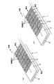
図1は、本発明の燃料電池セルスタックの構造を示す斜視図であり、図2はその平面図である。
この燃料電池セルスタック1は、発電素子接続部材7(図3参照)を塗布する前の状態を示している。
Hereinafter, embodiments of the present invention will be described in detail with reference to the accompanying drawings.
FIG. 1 is a perspective view showing a structure of a fuel cell stack according to the present invention, and FIG. 2 is a plan view thereof.
The
この燃料電池セルスタック1は、中空かつ扁平板状の支持体2に、複数の発電素子部をセルスタックの長手方向に沿って複数個配置し、それらをインターコネクタ6で直列に接続した「横縞形」といわれるものである。発電素子部は、支持体2の表面及び裏面にそれぞれ形成されている。
図1(a)は、セルスタック表面の先端の発電素子部(図示せず)と、セルスタック裏面の先端の発電素子部(図示せず)とが、セルスタックを周回する金属バンドによって接続され、セルスタック表面の電流の方向と、セルスタック裏面の電流の方向とが反対になるタイプを示している。
This
In FIG. 1A, a power generation element portion (not shown) at the front end of the cell stack and a power generation element portion (not shown) at the front end of the cell stack are connected by a metal band that goes around the cell stack. 1 shows a type in which the direction of current on the cell stack surface is opposite to the direction of current on the back surface of the cell stack.
図1(b)は、セルスタック表面の各発電素子部と、セルスタック裏面の各発電素子部とが、セルスタックを周回するインターコネクタ6によりそれぞれ接続されて、全体としてみればセルスタック表面の発電素子部と、セルスタック裏面の発電素子部とが、並列に接続されるタイプを示している。
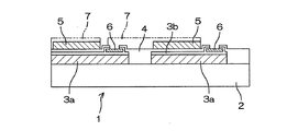
図3は、図2のAーA線で切った、発電素子部が形成された部分を示すセルスタックの断面図である。
FIG. 1B shows that each power generation element portion on the cell stack surface and each power generation element portion on the back surface of the cell stack are connected by an
FIG. 3 is a cross-sectional view of the cell stack showing a portion where the power generation element portion is formed, taken along line AA in FIG.
燃料電池セルスタック1は、支持体2の表面に、その長手方向に所定間隔をおいて、複数の発電素子部を配列することにより構成されている。
それぞれの発電素子部は、集電燃料極3a、活性燃料極3b(集電燃料極3a、活性燃料極3bを総称して「燃料極3」という)、固体電解質4及び空気極5を順次積層した層構造となっている。
The
Each power generation element section is formed by sequentially laminating a current
隣り合う発電素子部は、インターコネクタ6及び発電素子接続部材7により直列に接続されている。すなわち、一方の発電素子部の燃料極3の上にインターコネクタ6が形成され、このインターコネクタ6と他方の発電素子部の空気極5とが発電素子接続部材7により電気的に接続された構造となっている。
支持体2の内部には、内径の小さな複数の燃料ガス流路8が長手方向に貫通して形成されている(図1参照)。このように、支持体2の内部に燃料ガス流路8を複数形成することにより、支持体2の内部に大きな燃料ガス流路を1本形成する場合に比べて、支持体2を扁平板状とすることができ、支持体2の強度も上がる。
Adjacent power generation element portions are connected in series by an
A plurality of fuel gas passages 8 having a small inner diameter are formed in the
この燃料ガス流路8内に燃料ガス(水素ガス)を流し、かつ空気極5を空気等の酸素含有ガスに曝すことにより、燃料極3及び空気極5間で前述した式(1),(2)に示す電極反応が生じ、両極間に電位差が発生し、発電するようになっている。
前記燃料電池セルスタック1を複数集合して、燃料電池セルスタック1同士をセルスタック間接続部材で接続して、バンドルを組み立てる。このバンドルの両端に、バンドルで発生した電力を燃料電池外に取り出すための導電部材(図示せず)を取り付けて、収納容器内に収容して、燃料電池を製作することができる。この収納容器に空気等の酸素含有ガスを導入し、水素等の燃料ガスを導入管を通して燃料ガスマニホールドMに導入する。燃料ガスを燃料ガスマニホールドMを通して燃料電池セルスタック1内部に導入し、燃料電池セルスタック1を所定温度に加熱すれば、燃料電池セルスタック1によって発電することができる。使用された燃料ガス、酸素含有ガスは、収納容器外に排出される。
By flowing a fuel gas (hydrogen gas) through the fuel gas flow path 8 and exposing the
A bundle is assembled by assembling a plurality of the
以下、セルスタックを構成する各部材の材質を詳しく説明する。
前記支持体2は、Ni若しくはNi酸化物(NiO)と、例えば希土類元素酸化物が固溶したZrO2とからなっている。なお、希土類元素酸化物を構成する希土類元素としては、Y,La,Yb,Tm,Er,Ho,Dy,Gd,Sm,Prなどを例示することができるが、好ましいものは、Yの酸化物である。Y2O3やYb2O3、特にY2O3が好ましい。また、支持体2として、希土類元素酸化物が固溶したZrO2に代えて、例えばスピネル、フォルステライト、ジルコン酸カルシウム等を用いることもできる。
Hereinafter, the material of each member constituting the cell stack will be described in detail.
The
前記NiあるいはNiO(NiOは、発電時には、通常、水素ガスにより還元されてNiとして存在する)は、Ni換算で5〜25体積%、特に5〜10体積%の範囲で支持体2中に含有されているのがよい。
この支持体2の熱膨張係数は、通常、10.5〜11.5×10⁻⁶(1/K)程度である。
Ni or NiO (NiO is usually reduced by hydrogen gas and exists as Ni during power generation) is contained in the
The thermal expansion coefficient of the
支持体2は、発電素子部間の電気的ショートを防ぐために電気絶縁性であることが必要であり、Ni等の含量を前記範囲として、10Ω・cm以上の抵抗率を持たせることが好ましい。
また、Ni等以外の残量の全ては、通常、希土類元素酸化物が固溶しているZrO2である。しかし、少量、例えば5重量%以下の範囲で、MgOやSiO2などの他の酸化物、若しくは複合酸化物例えばジルコン酸カルシウムなどを含有していてもよい。
The
Further, the remaining amount other than Ni or the like is usually ZrO 2 in which a rare earth element oxide is dissolved. However, other oxides such as MgO and SiO 2 or composite oxides such as calcium zirconate may be contained in a small amount, for example, in the range of 5% by weight or less.
なお、前記支持体2は、燃料ガス流路8内の燃料ガスを燃料極3の表面まで導入可能でなければならず、このため、多孔質であることが必要である。一般に、その開気孔率は25%以上、特に30〜40%の範囲にあるのがよい。
燃料極3は、前記式(2)の電極反応を生じせしめるものであり、本実施形態においては、固体電解質側の活性燃料極3bと、支持体2側の集電燃料極3aとの二層構造に形成されている。
The
The
前記固体電解質側の活性燃料極3bは、多孔質の導電性セラミックスから形成される。例えば、希土類元素が固溶しているZrO2(安定化ジルコニア)と、Ni及び/又はNi酸化物NiO(以下、Ni等と呼ぶ)とからなる。この希土類元素が固溶した安定化ジルコニアとしては、後述する固体電解質4に使用されているものと同様のものを用いることができる。
The
活性燃料極3b中の安定化ジルコニア含量は、35〜65体積%の範囲にあることが好ましく、またNi等の含量は、良好な集電性能を発揮させるため、Ni換算で65〜35体積%の範囲にあるのがよい。
さらに活性燃料極3bの開気孔率は、20%以上、特に25〜40%の範囲にあるのがよい。
The stabilized zirconia content in the
Further, the open porosity of the
この活性燃料極3bの熱膨張係数は、通常、12.3×10⁻⁶(1/K)程度である。
また、活性燃料極3bの厚みは、3μm以上、10μm未満の範囲にあることが望ましい。厚み10μm以上であれば、固体電解質4との熱膨張差に起因して発生する熱応力を吸収できないようになり、活性燃料極の割れや剥離などを生じるおそれがある。
活性燃料極3bは、導電性であることが好ましく、Ni等の含量が前記範囲として、400S/cm以上の導電率を持たせることができる。
The thermal expansion coefficient of the
The thickness of the
The
一方、燃料極3のうち前記支持体2側の集電燃料極3aは、Ni若しくはNi酸化物と、希土類元素酸化物との混合体である。希土類元素酸化物を構成する希土類元素としては、Y,La,Yb,Tm,Er,Ho,Dy,Gd,Sm,Prなどを例示することができるが、好ましいものは、Yの酸化物である。Y2O3やYb2O3、特にY2O3が好ましい。
On the other hand, the current collecting
前記NiあるいはNi酸化物(NiOは、発電時には、通常、水素ガスにより還元されてNiとして存在する)は、Ni換算で35体積%〜60体積%の範囲で希土類元素酸化物中に含有されているのがよい。この範囲で調製することにより、集電燃料極3aの熱膨張係数は、通常、11.5×10⁻⁶(1/K)程度となる。
したがって、支持体2と集電燃料極3aとの熱膨張差を1.0×10⁻⁶/°C以下とすることができる。
The Ni or Ni oxide (NiO is usually reduced by hydrogen gas and present as Ni during power generation) is contained in the rare earth element oxide in a range of 35 vol% to 60 vol% in terms of Ni. It is good to be. By preparing in this range, the thermal expansion coefficient of the current collecting
Therefore, the thermal expansion difference between the
集電燃料極3aも、活性燃料極3bと同様、電流の流れを損なわないように、導電性であることが好ましく、Ni等の含量が前記範囲として、400S/cm以上の導電率をもたせることができる。
また、この集電燃料極3aの厚みは、100μm以上であることが望ましい。100μm未満であれば、長手方向に電流が流れるときの抵抗が増加して、燃料電池セルスタック1内部に無視できない電圧降下が発生してしまう。
The current
The thickness of the current collecting
以上のように、燃料極3を、固体電解質側の活性燃料極3bと支持体側の集電燃料極3aとの二層に形成した構造であれば、支持体側の集電燃料極3aのNi換算でのNi量あるいはNiO量を35〜60体積%の範囲内で調製することにより、活性燃料極3bとの接合性を損なうことなく、その熱膨張係数を、支持体2の熱膨張係数に近づけることができ、例えば両者の熱膨張差を、1.0×10⁻⁶/℃未満とすることができる。
As described above, if the
したがって、燃料電池セルスタック1の作製時、加熱時、冷却時などにおいて燃料極3と支持体2との熱膨張差に起因して発生する熱応力を小さくすることができるため、燃料極3の割れや剥離などを抑制することができる。そして、燃料ガス(水素ガス)を流して発電を行う場合においても、支持体2との熱膨張係数の整合性は安定に維持される。
前記固体電解質4は、電極間の電子の橋渡しをする電解質としての機能を有すると同時に、燃料ガスと空気等の酸素含有ガスとのリークを防止するためにガス遮断性を有していることが必要である。従って、固体電解質4としては、このような特性を備えている緻密質なセラミックス、例えば、3〜15モル%の希土類元素が固溶した安定化ZrO2を用いるのが好ましい。この安定化ZrO2中の希土類元素としては、Sc,Y,La,Ce,Pr,Nd,Pm,Sm,Eu,Gd,Tb,Dy,Ho,Er,Tm,Yb,Luを例示することができるが、安価であるという点で、Y,Ybが好適である。また、8YSZ(8モル%のYが固溶している安定化ZrO2)と熱膨張係数がほぼ等しいランタンガレート系固体電解質なども好適に用いることができる。
Therefore, since the thermal stress generated due to the difference in thermal expansion between the
The
前記の固体電解質4は、ガス透過を防止するという点から10〜100μmの厚みを有し、さらに相対密度(アルキメデス法による)が93%以上、特に95%以上であることが望ましい。
固体電解質4上に形成される空気極5は、前述した式(1)の電極反応を生じさせるものであり、いわゆるABO3型のペロブスカイト型酸化物からなる導電性セラミックスから形成される。このようなペロブスカイト型酸化物としては、遷移金属型ペロブスカイト酸化物、特にAサイトにLaを有するLaMnO3系酸化物、LaFeO3系酸化物、LaCoO3系酸化物の少なくとも一種が好適であり、600〜1000℃程度の比較的低温での電気伝導性が高いという点から、LaFeO3系酸化物が特に好適である。
It is desirable that the
The
なお、前記のペロブスカイト型酸化物においては、AサイトにLaと共にSrが存在していてもよいし、さらにBサイトには、Fe,Co,Mnが共存していてもよい。
また、前記の空気極5は、ガス透過性を有していなければならず、その開気孔率は20%以上、特に30〜50%の範囲にあるのがよい。さらに、その厚みは、集電性という点から30〜100μmであることが望ましい。
In the perovskite oxide, Sr may exist together with La at the A site, and Fe, Co, and Mn may coexist at the B site.
The
隣り合う発電素子部同士を直列に接続するために使用されるインターコネクタ6は、一方の発電素子部の燃料極3と他方の発電素子部の空気極5とを接続するものであり、導電性セラミックスから形成されるが、燃料ガス(水素ガス)及び空気等の酸素含有ガスと接触するため、耐還元性、耐酸化性を有していることが必要である。
インターコネクタ6は、厚み10μmから100μm程度の導電体である。インターコネクタ6は、一方の発電素子部の活性燃料極3bと他方の発電素子部の空気極5とを、発電素子接続部材7を介して接続するものであり、導電性セラミックスから形成される。燃料ガス(水素ガス)及び空気等の酸素含有ガスと接触するため、耐還元性、耐酸化性を有していることが必要である。このため、かかる導電性セラミックスとしては、一般に、ランタンクロマイト系のペロブスカイト型酸化物(LaCrO3系酸化物)が使用される。また、燃料ガス流路8を通る燃料ガスと空気極5の外部を通る空気等の酸素含有ガスとのリークを防止するため、かかる導電性セラミックスは緻密質でなければならず、例えば93%以上、特に95%以上の相対密度(アルキメデス法)を有していることが好適である。なお、このインターコネクタ6の端面と、固体電解質4の端面との間には、適当な接合層(例えばY2O3)を介在させることにより、シール性を向上させることもできる。
The
The
発電素子接続部材7は、一方の発電素子部のインターコネクタ6と他方の発電素子部の空気極5とを接続するものであり、インターコネクタ6と同様、導電性、耐酸化性を有する材料で形成される。ただし、ガスの遮断性は要求されないので、インターコネクタ6のように緻密でなくてもよい。
セルスタック間接続部材は、1つの燃料電池セルスタックのインターコネクタ6と、他の燃料電池セルスタックの空気極5とを接続する部材である。セルスタック間接続部材は、耐熱性、耐酸化性、電気伝導性という点から、Pt、Ag、Ni基合金、Fe−Cr鋼合金の少なくとも一種からなることが望ましい。このセルスタック間接続部材とインターコネクタ6、セルスタック間接続部材と空気極5の接続部に、AgやPt等の貴金属やNi等の金属を含有するペーストを導電性接着剤として用いて、接続信頼性を向上させることもできる。
The power generation
The inter-cell stack connecting member is a member that connects the
前述した燃料電池セルスタック1は、例えば以下のようにして製造することができる。
先ず、支持体2の材料として、平均粒径が0.1〜10μmのY2O3等の希土類元素酸化物が固溶したZrO2粉末と、Ni粉末(NiO粉末でもよい)とを用意し、これらの粉末を、所定の比率で混合する。この混合粉末に、ポアー剤と、セルロース系有機バインダーと、水とからなる溶媒とを混合し、押し出し成形して、内部に燃料ガス流路8を有する中空形状、扁平状の支持体成形体を作製する。
The
First, as a material for the
次に、集電燃料極の材料を作製する。例えば、NiO粉末、Ni粉末と、Y2O3等の希土類元素酸化物粉末とを混合し、これにポアー剤を添加し、アクリル系バインダーとトルエンを加えてスラリーとし、ドクターブレード法にて、厚み100〜150μmの集電燃料極テープを作製する。
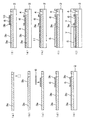
以下、燃料電池セルスタックの製造工程図である図4を参照して説明する。
Next, a material for the current collecting fuel electrode is prepared. For example, NiO powder, Ni powder, and rare earth element oxide powder such as Y 2 O 3 are mixed, a pore agent is added thereto, an acrylic binder and toluene are added to form a slurry, and a doctor blade method is used. A current collecting fuel electrode tape having a thickness of 100 to 150 μm is prepared.
Hereinafter, the fuel cell stack manufacturing process will be described with reference to FIG.
切断した集電燃料極テープ3aにおいて、絶縁体を形成する部分を打ち抜く(図4(a))。
次に、この集電燃料極テープ3a上のインターコネクタ形成部分に、活性燃料極3bを印刷する(図4(b))。
さらに、活性燃料極3b上に、インターコネクタ6を印刷する(図4(c))。
In the cut current collecting
Next, the
Further, the
そしてもう一度、インターコネクタ6の中央部分を除いて活性燃料極3bを全体に印刷する(図4(d))。
次に、この状態で、燃料極テープ3aを、支持体成形体2に横縞状に貼り付ける。その際の燃料極テープ3aと他の燃料極テープ3aとは、3mm程度の間隔をあけて配置する。そして、この積層体を乾燥し、900〜1100℃の温度範囲で仮焼する。(図4(e))。
Then, once again, the
Next, in this state, the
インターコネクタ6の、前記活性燃料極3bを印刷しなかった中央部分に、有機物シート(マスキングテープ)10を貼り付ける(図4(f))。
次に、この積層体を、8YSZ(8モル%のYが固溶したZrO2粉末)にアクリル系バインダーとトルエンを加えてスラリーとした固体電解質溶液に漬けて、固体電解質溶液から取り出す。このディップにより、積層体の一面に固体電解質4の層が塗布されるとともに、前記(a)で打ち抜いた空間に絶縁体である固体電解質4が充填される。
An organic material sheet (masking tape) 10 is attached to the central portion of the
Next, this laminate is immersed in a solid electrolyte solution obtained by adding an acrylic binder and toluene to 8YSZ (ZrO 2 powder in which 8 mol% of Y is solid-dissolved), and is taken out from the solid electrolyte solution. By this dipping, a layer of the
この状態で、800°C、1時間仮焼きする。この仮焼き中に、有機物シート10とその上に塗布された固体電解質4の層を除去することができる(図4(g))。
次に空気極の形成部分に反応防止層11を塗布して1480°C、2時間焼成する(図4(h))。その反応防止層11の上から、空気極5を印刷し1050°C、2時間焼き付ける(図4(i))。
In this state, calcining is performed at 800 ° C. for 1 hour. During the calcination, the
Next, the
最後に、1つの発電素子部のインターコネクタ6と、これに隣接する発電素子部の空気極5とを接続するための発電素子接続部材7を貼り付けて(図4(j))、燃料電池セルスタックが完成する。
以上で、本発明の実施の形態を説明したが、本発明の実施は、前記の形態に限定されるものではない。例えば、前記の例では支持体2は、中空の板状で内部に複数の燃料ガス流路8を有するものとして説明したが、支持体2は、円筒状でもよく、燃料ガス流路8の数は一つでもよいことはいうまでもない。その他、本発明の範囲内で種々の変更を施すことが可能である。
Finally, a power generation
Although the embodiments of the present invention have been described above, the embodiments of the present invention are not limited to the above-described embodiments. For example, in the above example, the
1 燃料電池セルスタック
2 支持体
3 燃料極
3a 集電燃料極
3b 活性燃料極
4 固体電解質
5 空気極
6 インターコネクタ
7 発電素子接続部材
8 燃料ガス流路
10 有機物シート
11 反応防止層
DESCRIPTION OF
Claims (8)
前記インターコネクタが、前記発電素子部の前記燃料極の上に層状に形成されているとともに、前記固体電解質が前記インターコネクタの上面における前記支持体の長手方向の両端部を被覆した状態で前記燃料極の上に形成されており、
前記インターコネクタの前記固体電解質で被覆されていない露出した部分と、隣り合う前記発電素子部の前記空気極との間を接続する発電素子接続部材がさらに設けられ、
前記燃料極が、前記固体電解質側の活性燃料極と前記支持体側の集電燃料極とからなるとともに、
前記活性燃料極が、Ni若しくはNi酸化物と、希土類元素が固溶しているZrO2との混合体からなり、
前記集電燃料極が、Ni若しくはNi酸化物と、希土類元素酸化物との混合体からなり、
前記インターコネクタが、前記活性燃料極の上に形成されていることを特徴とする燃料電池セルスタック。 A power generation element portion in which a fuel electrode, a solid electrolyte, and an air electrode are laminated in this order on the surface of a columnar electrically insulating support having a single or a plurality of fuel gas flow paths formed in the longitudinal direction. A fuel cell stack in which a plurality of power generating element portions are connected in series via an interconnector, provided at a predetermined interval,
The interconnector is formed in layers on the fuel electrode of the power generation element portion, and the fuel is covered with the solid electrolyte covering both longitudinal ends of the support on the upper surface of the interconnector. Formed on the pole,
A power generation element connection member that connects between the exposed portion of the interconnector that is not covered with the solid electrolyte and the air electrode of the adjacent power generation element portion is further provided,
The fuel electrode comprises an active fuel electrode on the solid electrolyte side and a current collecting fuel electrode on the support side,
The active fuel electrode is made of a mixture of Ni or Ni oxide and ZrO 2 in which a rare earth element is dissolved,
The current collecting fuel electrode is made of Ni or a mixture of Ni oxide and rare earth element oxide,
The fuel cell stack, wherein the interconnector is formed on the active fuel electrode.
Priority Applications (1)
| Application Number | Priority Date | Filing Date | Title |
|---|---|---|---|
| JP2009211877A JP5241663B2 (en) | 2009-09-14 | 2009-09-14 | Solid electrolyte fuel cell stack, bundle and fuel cell |
Applications Claiming Priority (1)
| Application Number | Priority Date | Filing Date | Title |
|---|---|---|---|
| JP2009211877A JP5241663B2 (en) | 2009-09-14 | 2009-09-14 | Solid electrolyte fuel cell stack, bundle and fuel cell |
Related Parent Applications (1)
| Application Number | Title | Priority Date | Filing Date |
|---|---|---|---|
| JP2004162589A Division JP4851692B2 (en) | 2004-05-31 | 2004-05-31 | Solid electrolyte fuel cell stack, bundle and fuel cell |
Publications (2)
| Publication Number | Publication Date |
|---|---|
| JP2010016000A JP2010016000A (en) | 2010-01-21 |
| JP5241663B2 true JP5241663B2 (en) | 2013-07-17 |
Family
ID=41701884
Family Applications (1)
| Application Number | Title | Priority Date | Filing Date |
|---|---|---|---|
| JP2009211877A Expired - Fee Related JP5241663B2 (en) | 2009-09-14 | 2009-09-14 | Solid electrolyte fuel cell stack, bundle and fuel cell |
Country Status (1)
| Country | Link |
|---|---|
| JP (1) | JP5241663B2 (en) |
Families Citing this family (8)
| Publication number | Priority date | Publication date | Assignee | Title |
|---|---|---|---|---|
| KR101204140B1 (en) * | 2010-07-26 | 2012-11-22 | 삼성전기주식회사 | Solid oxide fuel cell and manufacturing method thereof |
| JP5334327B2 (en) * | 2010-08-06 | 2013-11-06 | 日本碍子株式会社 | Fuel cell structure |
| JP2012038583A (en) * | 2010-08-06 | 2012-02-23 | Ngk Insulators Ltd | Structure of fuel cell |
| JP5555682B2 (en) * | 2010-11-01 | 2014-07-23 | 日本碍子株式会社 | Solid oxide fuel cell |
| JP2012099322A (en) * | 2010-11-01 | 2012-05-24 | Ngk Insulators Ltd | Solid oxide fuel cell |
| JP5502180B2 (en) * | 2011-11-24 | 2014-05-28 | 日本碍子株式会社 | Solid oxide fuel cell |
| JP2016095922A (en) * | 2014-11-12 | 2016-05-26 | Toto株式会社 | Solid oxide fuel cell, manufacturing method and manufacturing apparatus thereof |
| US11605821B2 (en) * | 2018-04-26 | 2023-03-14 | Kyocera Corporation | Solid oxide type fuel battery cell |
Family Cites Families (10)
| Publication number | Priority date | Publication date | Assignee | Title |
|---|---|---|---|---|
| JPS6443973A (en) * | 1987-08-11 | 1989-02-16 | Agency Ind Science Techn | Solid electrolyte fuel cell electrode |
| JPH0758615B2 (en) * | 1989-10-18 | 1995-06-21 | 工業技術院長 | Solid electrolyte fuel cell |
| US5045169A (en) * | 1990-02-05 | 1991-09-03 | Westinghouse Electric Corp. | Solid oxide electrolyte electrochemical oxygen generator |
| US5200279A (en) * | 1991-10-11 | 1993-04-06 | Westinghouse Electric Corp. | Solid oxide fuel cell generator |
| JP2775081B2 (en) * | 1992-04-20 | 1998-07-09 | 大阪瓦斯株式会社 | Method for producing thin film for solid oxide fuel cell |
| JPH10247499A (en) * | 1997-02-28 | 1998-09-14 | Toto Ltd | Cylindrical warp streak solid electrolyte fuel cell |
| JPH11111309A (en) * | 1997-10-06 | 1999-04-23 | Mitsubishi Heavy Ind Ltd | Manufacture of solid electrolyte fuel cell |
| US6416897B1 (en) * | 2000-09-01 | 2002-07-09 | Siemens Westinghouse Power Corporation | Tubular screen electrical connection support for solid oxide fuel cells |
| JP3914990B2 (en) * | 2003-11-18 | 2007-05-16 | 独立行政法人産業技術総合研究所 | Cylindrical fuel cell |
| JP4761104B2 (en) * | 2004-05-13 | 2011-08-31 | 独立行政法人産業技術総合研究所 | Cylindrical fuel cell |
-
2009
- 2009-09-14 JP JP2009211877A patent/JP5241663B2/en not_active Expired - Fee Related
Also Published As
| Publication number | Publication date |
|---|---|
| JP2010016000A (en) | 2010-01-21 |
Similar Documents
| Publication | Publication Date | Title |
|---|---|---|
| JP5175527B2 (en) | Cell stack and fuel cell | |
| JP5118865B2 (en) | Horizontally-striped fuel cell and method for producing the same | |
| JP5080951B2 (en) | Horizontal stripe fuel cell stack and fuel cell | |
| JP4741815B2 (en) | Cell stack and fuel cell | |
| JP5241663B2 (en) | Solid electrolyte fuel cell stack, bundle and fuel cell | |
| JP5132878B2 (en) | Fuel cell, fuel cell stack and fuel cell | |
| JP5192702B2 (en) | Horizontally-striped fuel cell, cell stack, and fuel cell | |
| JP4851692B2 (en) | Solid electrolyte fuel cell stack, bundle and fuel cell | |
| JP5192723B2 (en) | Horizontally-striped fuel cell and fuel cell | |
| JP5175461B2 (en) | Horizontally-striped fuel cell and fuel cell | |
| JP5417543B1 (en) | Horizontal stripe fuel cell | |
| JP4718959B2 (en) | Horizontal stripe fuel cell | |
| JP2004179071A (en) | Fuel cell and fuel cell | |
| JP2005093241A (en) | Solid electrolyte fuel cell | |
| JP2012038586A (en) | Structure of fuel cell | |
| JP5437152B2 (en) | Horizontally-striped solid oxide fuel cell stack and fuel cell | |
| JP5179131B2 (en) | Horizontal stripe fuel cell and fuel cell | |
| JP5449076B2 (en) | Fuel cell | |
| JP4465175B2 (en) | Solid electrolyte fuel cell | |
| JP5132879B2 (en) | Horizontal stripe fuel cell and fuel cell | |
| JP5179153B2 (en) | Horizontally-striped fuel cell, cell stack, and fuel cell | |
| JP4925574B2 (en) | Fuel cell and fuel cell | |
| JP2007250368A (en) | Horizontal stripe fuel cell and fuel cell | |
| JP6169932B2 (en) | Solid oxide fuel cell | |
| JP5334327B2 (en) | Fuel cell structure |
Legal Events
| Date | Code | Title | Description |
|---|---|---|---|
| A131 | Notification of reasons for refusal |
Free format text: JAPANESE INTERMEDIATE CODE: A131 Effective date: 20120712 |
|
| A521 | Request for written amendment filed |
Free format text: JAPANESE INTERMEDIATE CODE: A523 Effective date: 20120906 |
|
| A131 | Notification of reasons for refusal |
Free format text: JAPANESE INTERMEDIATE CODE: A131 Effective date: 20121206 |
|
| A521 | Request for written amendment filed |
Free format text: JAPANESE INTERMEDIATE CODE: A523 Effective date: 20130128 |
|
| TRDD | Decision of grant or rejection written | ||
| A01 | Written decision to grant a patent or to grant a registration (utility model) |
Free format text: JAPANESE INTERMEDIATE CODE: A01 Effective date: 20130314 |
|
| A61 | First payment of annual fees (during grant procedure) |
Free format text: JAPANESE INTERMEDIATE CODE: A61 Effective date: 20130402 |
|
| FPAY | Renewal fee payment (event date is renewal date of database) |
Free format text: PAYMENT UNTIL: 20160412 Year of fee payment: 3 |
|
| R150 | Certificate of patent or registration of utility model |
Free format text: JAPANESE INTERMEDIATE CODE: R150 Ref document number: 5241663 Country of ref document: JP Free format text: JAPANESE INTERMEDIATE CODE: R150 |
|
| R250 | Receipt of annual fees |
Free format text: JAPANESE INTERMEDIATE CODE: R250 |
|
| R250 | Receipt of annual fees |
Free format text: JAPANESE INTERMEDIATE CODE: R250 |
|
| R250 | Receipt of annual fees |
Free format text: JAPANESE INTERMEDIATE CODE: R250 |
|
| R250 | Receipt of annual fees |
Free format text: JAPANESE INTERMEDIATE CODE: R250 |
|
| R250 | Receipt of annual fees |
Free format text: JAPANESE INTERMEDIATE CODE: R250 |
|
| R250 | Receipt of annual fees |
Free format text: JAPANESE INTERMEDIATE CODE: R250 |
|
| R250 | Receipt of annual fees |
Free format text: JAPANESE INTERMEDIATE CODE: R250 |
|
| R250 | Receipt of annual fees |
Free format text: JAPANESE INTERMEDIATE CODE: R250 |
|
| LAPS | Cancellation because of no payment of annual fees |