JP5240030B2 - vending machine - Google Patents
vending machine Download PDFInfo
- Publication number
- JP5240030B2 JP5240030B2 JP2009097072A JP2009097072A JP5240030B2 JP 5240030 B2 JP5240030 B2 JP 5240030B2 JP 2009097072 A JP2009097072 A JP 2009097072A JP 2009097072 A JP2009097072 A JP 2009097072A JP 5240030 B2 JP5240030 B2 JP 5240030B2
- Authority
- JP
- Japan
- Prior art keywords
- heating
- cooling
- temperature
- refrigerant
- solenoid valve
- Prior art date
- Legal status (The legal status is an assumption and is not a legal conclusion. Google has not performed a legal analysis and makes no representation as to the accuracy of the status listed.)
- Active
Links
Images


Description
本発明は、缶、ビン、パック、ペットボトル等の容器に入れた飲料等の商品を冷媒回路にて冷却または加熱して販売に供する自動販売機に関する。 The present invention relates to a vending machine that sells a product such as a beverage in a container such as a can, a bottle, a pack, or a plastic bottle after being cooled or heated in a refrigerant circuit.
近年の地球温暖化に対して二酸化炭素の排出量削減が課題となっており、自動販売機も省エネ型が開発されている。その1方式として従来は排熱していた凝縮器の熱を庫内の加熱に利用するヒートポンプ方式の自動販売機が開発されている(例えば、特許文献1参照)。
特許文献1に記載された自動販売機は、複数の商品収納庫にそれぞれ内部熱交換器を設け、商品収納庫外に設けた圧縮機、外部熱交換器と接続して、電動膨張弁の開度調整、電磁弁の切り替えにより、各商品収納庫の冷却もしくは加熱の設定を行い、内部熱交換器を凝縮器として使用するヒートポンプ運転を行っている。また、冷却加熱の設定モードは、商品収納庫の冷却もしくは加熱の運転をC、Hの記号を用いて示すものであり、正面から見て商品収納庫の左側から順に、例えば、すべてが冷却の場合にはCCCモード、右の商品収納庫のみが加熱の場合にはCCHモードなどと記される。
Reducing carbon dioxide emissions has become a challenge with recent global warming, and energy-saving vending machines have been developed. As one of the methods, a heat pump type vending machine that uses the heat of the condenser, which has been exhausted in the past, for heating in the cabinet has been developed (for example, see Patent Document 1).
The vending machine described in Patent Document 1 is provided with an internal heat exchanger in each of a plurality of product storages, and is connected to a compressor and an external heat exchanger provided outside the product storage to open an electric expansion valve. By adjusting the degree and switching the electromagnetic valve, each product storage is set for cooling or heating, and a heat pump operation is performed using the internal heat exchanger as a condenser. In addition, the cooling and heating setting mode indicates the operation of cooling or heating the product storage using symbols C and H. For example, all the cooling is performed in order from the left side of the product storage as viewed from the front. In the case, the CCC mode is indicated. When only the right product storage is heated, the CCH mode is indicated.
そして、商品収納庫の温度を検知して適正温度に到達をすると、その商品収納庫の内部熱交換器に接続されている電動膨張弁、電磁弁を閉止して、その商品収納庫の冷却もしくは加熱を停止したサーモサイクル運転が行われる。例えば、冷却加熱の設定モードがCHHモードのヒートポンプ運転で冷却加熱が行われる場合、加熱している中側の商品収納庫(中庫とも称する)の温度を検知して適正温度に到達をする(サーモOFF温度に到達をする)と、左側と右側の商品収納庫(左庫、右庫とも称する)のみでヒートポンプ運転が行われる。さらに、このヒートポンプ運転でのモードが継続され、加熱している右側の商品収納庫の温度を検知して適正温度に到達をすると、右側の商品収納庫の電動膨張弁、電磁弁を閉止して、加熱を停止し、外部熱交換器と左側の商品収納庫の内部熱交換器による冷却単独運転行われる。そして、すべての商品収納庫の温度が適正温度に到達をすると、圧縮機を停止して冷却加熱運転を停止する。 Then, when the temperature of the product storage is detected and the proper temperature is reached, the electric expansion valve and the electromagnetic valve connected to the internal heat exchanger of the product storage are closed, and the product storage is cooled or A thermocycle operation is performed with the heating stopped. For example, when cooling heating is performed in the heat pump operation in which the setting mode of cooling heating is the CHH mode, the temperature of the heating inner product storage (also referred to as a storage) is detected to reach an appropriate temperature ( When the thermo-off temperature is reached), the heat pump operation is performed only in the left and right product storages (also referred to as the left and right boxes). Furthermore, when the mode of this heat pump operation is continued and the temperature of the heated right product storage is detected and the appropriate temperature is reached, the electric expansion valve and electromagnetic valve of the right product storage are closed. Then, the heating is stopped, and the single cooling operation is performed by the external heat exchanger and the internal heat exchanger of the left product storage. And if the temperature of all the goods storage reaches | attains appropriate temperature, a compressor will be stopped and cooling heating operation will be stopped.
また、ヒートポンプ運転で加熱能力が不足する場合にはヒータが使用され、冷却している商品収納庫がすべて適正温度に到達し、かつ、加熱している商品収納庫がまだ適正温度に到達しない場合には、圧縮機を停止してヒータのみ加熱単独運転が行われることになる。
やがて、冷却休止中の商品収納庫が適正温度外に到達(サーモON温度に到達)すると、圧縮機を再起動して、サーモサイクル運転が行われる。
ところで、圧縮機の起動時、過負荷状態にあると電動機がロックし電動機の巻線に大電流が流れ、長時間流れると巻線の焼損が生じる。従来はこれを防止するためにロックが起こった時、圧縮機を停止させ圧縮機の吐出側と吸入側との圧力平衡がとれるまでの時間を待って圧縮機を再起動させていた(例えば特許文献2)。
Also, when the heating capacity is insufficient in the heat pump operation, the heater is used, all the product storages that have been cooled have reached the appropriate temperature, and the product storage that has been heated has not yet reached the appropriate temperature In this case, the compressor is stopped and only the heater is operated for heating alone.
Eventually, when the product storage in the cooling pause reaches outside the appropriate temperature (reaches the thermo-ON temperature), the compressor is restarted and the thermo-cycle operation is performed.
By the way, when the compressor is started, if the motor is in an overload state, the motor is locked and a large current flows through the winding of the motor. Conventionally, when a lock occurs to prevent this, the compressor is stopped and the compressor is restarted after waiting for a time until the pressure equilibrium between the discharge side and the suction side of the compressor is achieved (for example, patents). Reference 2).
しかしながら、この種の自動販売機では、圧縮機を停止させ圧縮機の吐出側と吸入側との圧力平衡中に加熱停止中の商品収納庫がサーモON温度に達する(加熱要求が出される)と、ヒータによる加熱単独運転となる。ヒータによる加熱効率はヒートポンプ運転による加熱効率より劣るので、消費電力が必要以上に増加することになる。
なお、圧縮機停止中に予め電磁弁を開成して圧力平衡させておけば、圧縮機を速やかに再起動できるが、この場合には、商品収納庫の内部熱交換器内の冷却された冷媒が商品収納庫外の配管に流出して冷媒温度が上昇し、同様に内部熱交換器内の加熱された冷媒が商品収納庫外の配管に流出して冷媒温度が低下するので、再運転したとき冷却加熱の運転時間が増加するとともに、消費電力も増加する。
本発明は上記に鑑みなされたもので、ヒータによる加熱単独運転を抑制して消費電力を低減しつつ効率的な冷却加熱運転ができる自動販売機を提供することを目的とする。
However, in this type of vending machine, when the compressor is stopped and the product storage in the heating stopped during the pressure equilibrium between the discharge side and the suction side of the compressor reaches the thermo-ON temperature (a heating request is issued). The heating alone operation by the heater is performed. Since the heating efficiency by the heater is inferior to the heating efficiency by the heat pump operation, the power consumption increases more than necessary.
In addition, if the solenoid valve is opened in advance and the pressure is balanced while the compressor is stopped, the compressor can be restarted quickly. In this case, the cooled refrigerant in the internal heat exchanger of the product storage Flowed out to the piping outside the product storage and the refrigerant temperature rose, and similarly, the heated refrigerant in the internal heat exchanger flowed out to the piping outside the product storage and the refrigerant temperature decreased, so it was restarted. Sometimes the cooling heating operation time increases and the power consumption also increases.
The present invention has been made in view of the above, and an object thereof is to provide a vending machine capable of performing an efficient cooling and heating operation while suppressing power single operation by a heater and reducing power consumption.
上記の目的を達成するために、本発明の請求項1に係る自動販売機は、複数の冷却加熱兼用の商品収納庫を有し、冷却加熱の冷却加熱設定モードにより選択的に商品収納庫を冷却もしくは加熱する自動販売機であって、冷媒を圧縮する圧縮機と、庫外に設け凝縮器電磁弁を介して冷媒を凝縮する凝縮器と、冷媒を膨張させる膨張手段と、膨張手段より膨張した冷媒を分配する分配器と、庫内に設け前記分配器より冷却器入口電磁弁を介して冷媒を蒸発する複数の庫内熱交換器と、蒸発した冷媒を冷却器出口電磁弁を介して合流する合流器と、にて冷却循環回路を構成するとともに、前記冷却循環回路に、前記圧縮機から加熱器電磁弁を介して前記庫内熱交換器と前記冷却器入口電磁弁との間に配管接続し、かつ、前記庫内熱交換器と前記冷却器出口電磁弁の間より庫外熱交換器、第2膨張手段を経由して前記分配器に配管接続することにより、前記庫内熱交換器を凝縮器として作用させてヒートポンプ運転を行う加熱冷却循環回路を構成し、冷却加熱兼用の商品収納庫に加熱ヒータを有し、ヒートポンプ運転を行わずに当該加熱ヒータのみで加熱単独運転を行う制御と、商品収納庫内に温度センサを有し、当該温度センサにより検出した温度と予め設定したサーモON温度、サーモOFF温度とを比較して前記冷却器入口電磁弁、前記冷却器出口電磁弁、前記凝縮器電磁弁、前記加熱器電磁弁の切替、あるいは、加熱ヒータの通電にて複数の商品収納庫の冷却もしくは加熱するサーモサイクル制御と、前記圧縮機の起動時に前記冷却器入口電磁弁、前記冷却器出口電磁弁、前記加熱器電磁弁を開成して圧縮機の出入口間の圧力を平衡にする圧力平衡調整制御と、を行う制御装置をもってなる自動販売機において、前記制御装置が圧力平衡調整中に加熱する商品収納庫内の温度がサーモON温度に達した場合にも加熱単独運転に移行せず、圧力平衡調整終了後に運転を再開することを特徴とする。 In order to achieve the above object, a vending machine according to claim 1 of the present invention has a plurality of product storages for both cooling and heating, and selectively stores the product storage by a cooling and heating setting mode for cooling and heating. A vending machine that cools or heats, a compressor that compresses the refrigerant, a condenser that is provided outside the refrigerator and condenses the refrigerant via a condenser solenoid valve, an expansion means that expands the refrigerant, and an expansion by the expansion means A distributor that distributes the refrigerant, a plurality of internal heat exchangers that evaporate the refrigerant from the distributor through the cooler inlet solenoid valve, and the evaporated refrigerant through the cooler outlet solenoid valve. And a confluencer for merging with each other to form a cooling circulation circuit, and to the cooling circulation circuit from the compressor through a heater solenoid valve, between the internal heat exchanger and the cooler inlet solenoid valve. Pipe connection, and the internal heat exchanger and the cooling Heating / cooling circulation in which heat pump operation is performed by connecting the internal heat exchanger as a condenser by connecting a pipe to the distributor via an external heat exchanger and second expansion means from between the outlet solenoid valves Constructing a circuit, having a heater in the product storage that is also used for cooling and heating, controlling the heating alone operation only with the heater without performing the heat pump operation, and having a temperature sensor in the product storage, Comparing the temperature detected by the temperature sensor with a preset thermo ON temperature, thermo OFF temperature, switching between the cooler inlet solenoid valve, the cooler exit solenoid valve, the condenser solenoid valve, and the heater solenoid valve; Alternatively, a thermocycle control that cools or heats a plurality of product storage boxes by energizing a heater, and the cooler inlet solenoid valve, the cooler outlet solenoid valve, and the heating when the compressor is started In a vending machine having a control device that opens a solenoid valve and balances the pressure between the inlet and outlet of the compressor, the control device heats up during the pressure balance adjustment. Even when the temperature reaches the thermo-ON temperature, the operation is not resumed but the operation is resumed after the pressure balance adjustment is completed.
本発明に係る請求項1の自動販売機は、圧力平衡調整中に加熱する商品収納庫内の温度がサーモON温度に達した場合にも加熱単独運転に移行せず、圧力平衡調整終了後に運転を再開する制御装置を有することにより、加熱ヒータによる加熱単独運転を低減しヒートポンプ運転を増加させることにより消費電力を低減することができる。 The vending machine according to the first aspect of the present invention does not shift to the heating single operation even when the temperature in the product storage to be heated during the pressure balance adjustment reaches the thermo-ON temperature, and operates after the pressure balance adjustment is completed. By having the control device that resumes the power consumption, it is possible to reduce the power consumption by reducing the single heating operation by the heater and increasing the heat pump operation.
以下に添付図面を参照して、本発明に係る自動販売機の好適な実施例を詳細に説明する。なお、この実施例によりこの発明が限定されるものではない。
まず、本発明の実施例に係る自動販売機について図1の斜視図、図2の断面図により説明する。これら図において、自動販売機は、前面が開口した直方状の断熱体として形成された本体キャビネット10と、その前面に設けられた外扉20および内扉30と、本体キャビネット10の内部を上下2段に底板11にて区画形成し、上部を例えば2つの断熱仕切板40wによって仕切られた3つの独立した商品収納庫40a、40b、40cと、下部に商品収納庫40a、40b、40cを冷却もしくは加熱する冷却/加熱ユニット60を収納する機械室50と、外扉20の内側に配設され、商品収納庫40a、40b、40c内の温度センサTa、Tb、Tcにより自動販売機の冷却、加熱運転などを制御する制御装置90と、を有して構成されている。
Exemplary embodiments of a vending machine according to the present invention will be described below in detail with reference to the accompanying drawings. Note that the present invention is not limited to the embodiments.
First, a vending machine according to an embodiment of the present invention will be described with reference to a perspective view of FIG. 1 and a sectional view of FIG. In these drawings, the vending machine includes a
より詳細に説明すると、外扉20は、本体キャビネット10の前面開口を開閉するためのものであり、図には明示していないが、この外扉20の前面には、販売する商品の見本を展示する商品展示室、販売する商品を選択するための選択ボタン、貨幣を投入するための貨幣投入口、払い出された商品を取り出すための商品取出口21等々、商品の販売に必要となる構成が配置してある。
内扉30は、商品収納庫40a、40b、40cの前面を開閉し、内部の商品を保温するものであり、上下2段に分割され内部に断熱体を有する箱型形状の構造体である。上側の内扉30aは、一端を外扉20に枢軸し、他端を外扉20に係着して、外扉20の開放と同時に上側の内扉30aを開放させて、商品の補充を容易にするものである。下側の内扉30bは、一端を本体キャビネット10に枢軸し、他端を本体キャビネット10に不図示の掛金にて掛着して、外扉20を開放したときには、閉止した状態であり、商品収納庫40a、40b、40c内の冷気もしくは暖気が流出することを防ぎ、メンテナンス時など必要に応じて開放できるものである。
More specifically, the outer door 20 is used to open and close the front opening of the
The
商品収納庫40a、40b、40cは、缶入り飲料やペットボトル入り飲料等の商品を所望の温度に維持した状態で収容するためのものであり、その収納庫の容量は商品収納庫40a、40c、40bの順番に大きな態様で配分されている。本実施例は、商品収納庫40aを冷却専用とし、商品収納庫40b、40cを冷却加熱兼用としている。その商品収納庫40a、40b、40cには、それぞれ、商品を上下方向に沿って並ぶ態様で収納し、販売信号により1個ずつ商品を排出するための商品搬出機構を備えた商品収納ラックR、排出された商品Sを内扉30bに取設された搬出扉31を介して外扉の商品取出口21へ搬出する商品搬出シュート42を有している。
冷却/加熱ユニット60は、機械室50内に圧縮機61、凝縮器62、膨張器63、第2の膨張器79、アキュムレータ69、庫外熱交換器76を取設し、底板11を跨いで庫内に庫内熱交換器65a、65b、65cを有して各機器を冷媒配管で接続されることにより構成されている。冷却/加熱ユニット60は、冷却加熱の設定モードに応じて、庫内に冷気または暖気を循環させて商品収納ラックR内の商品Sを冷却または加熱するものである。
The
The cooling /
冷却加熱用の圧縮機61は、冷媒を圧縮して回路内を循環させるためのもので、冷却運転時には、蒸発温度が約−10℃、凝縮温度が約40℃で使用され、加熱運転時には、蒸発温度が約−10℃、凝縮温度が約70℃で使用される。
凝縮器62は、フィンチューブ型の熱交換器であり、冷却運転時に不要な凝縮熱を排出するためのものである。凝縮器62の後部にはファン62fが取設され、ファン62fは機械室50の前面開口部より空気を吸入し、凝縮器62による凝縮熱を吸入するとともに、圧縮機61の排熱を吸収して、機械室50の背面開口部へ排気するためのものである。
膨張器63は、冷却運転時に通過する冷媒を減圧して断熱膨張させるものであり、たとえばキャピラリ、固定式膨張弁である。また、温度膨張弁、電子膨張弁であってもよい。
分流器64は、膨張器63で断熱膨張させられた冷媒を庫内熱交換器65a、65b、65cに分配するためのものである。
The
The
The
The
庫内熱交換器65a、65b、65cは、商品収納庫40a、40b、40cを冷却するためのものであり、庫内熱交換器65b、65cは、商品収納庫40b、40cを加熱する庫内熱交換器を兼用している。庫内熱交換器の容量は、商品収納庫の容量に対応して65a、65c、65bの順番に大きな態様で配分されている。また、庫内熱交換器65a、65b、65cは、各商品収納庫の下部に取設され、風胴67で囲繞され、その後方にファン65fが取設され、その後方にダクト67dが取設されている。商品収納庫内の冷却と加熱は、庫内熱交換器65a、65b、65cにより冷却もしくは加熱された空気を商品収納庫内の商品Sに送風し、図2中の矢印で示すようにダクト67dより循環回収することで行われる。
アキュムレータ69は、庫内熱交換器65a、65b、65cから蒸発された冷媒を流入し、気液分離させて液冷媒を貯留し、気相冷媒を圧縮機61に戻すための密閉した容器である。また、アキュムレータ69は、回路の冷媒循環に余った冷媒を貯留するための容器でもある。
The
The
庫外熱交換器76は、フィンチューブ型の熱交換器であり、加熱運転時に不要な凝縮熱を排出するためのものである。
膨張器79は、加熱運転時に通過する冷媒を減圧して断熱膨張させるものであり、たとえばキャピラリ、固定式膨張弁である。また、温度膨張弁、電子膨張弁であってもよい。
ヒータ66b、66cは庫内熱交換器65b、65cの前方に取設され、ヒートポンプ運転を行わずに加熱単独運転を行う場合に商品収納庫40b、40cの加熱を行うものである。
庫内温センサTa、Tb、Tcは、商品収納庫40a、40b、40c内の風胴67の上面に取設され、商品収納庫40a、40b、40cの庫内温度を検知するためのものである。
The
The
The
The inside temperature sensors Ta, Tb, Tc are installed on the upper surface of the
凝縮器電磁弁68は、圧縮機61と凝縮器62間の冷媒通路を開閉するものであり、加熱器電磁弁68b、68cは、圧縮機61と庫内熱交換器65b、65c間の圧縮された冷媒の通路を開閉するものである。冷却器入口電磁弁70a,70b,70cは分流器64と庫内熱交換器65a、65b、65c間の膨張された冷媒の通路を開閉するものであり、冷却器出口電磁弁72b,72cは、庫内熱交換器65b、65cと圧縮機61と間の蒸発された冷媒の通路を開閉するものである。
冷却/加熱ユニット60の冷媒回路構成について、図3の冷媒回路図を用いて詳述する。冷媒回路構成は、庫内を冷却のみを行う冷却循環回路60Aと庫内の冷却加熱を同時に行う(ヒートポンプ運転を行う)加熱冷却循環回路60Bを有している。なお、図中の点線の囲いは、商品収納庫40a、40b、40cを模式的に示している。
The
The refrigerant circuit configuration of the cooling /
冷却循環回路60Aは、圧縮機61から凝縮器62、膨張器63を経由して分流器64に接続し、分流器64から庫内熱交換器65a、65b、65cに分流したのち集合器67にて集合し、アキュムレータ69を経由して圧縮機61に戻る回路である。具体的には、冷却循環回路60Aの管路は、圧縮機61から凝縮器電磁弁68、凝縮器62、膨張器63を経由して分流器64に接続する管路と、分流器64より3方に分流して冷却器入口電磁弁70a、70b、70cに至る管路と、冷却器入口電磁弁70aから庫内熱交換器65aを経由して集合器67に至る管路と、冷却器入口電磁弁70b、70cからそれぞれ逆止弁71b、71cを介して庫内熱交換器65b、65cに至りさらに冷却器出口電磁弁72b、72cを介して集合部67に集合する管路と、集合部67からアキュムレータ69を経由して圧縮機61に戻る管路により構成されている。
The
一方、加熱冷却循環回路60Bには、冷却循環回路60Aに加えて、圧縮機61より凝縮器電磁弁68と並列接続されそれぞれ加熱器電磁弁68b、68cを経由してそれぞれ逆止弁71b、71cと庫内熱交換器65b、65cとの中間点に接続する管路と、庫内熱交換器65b、65cと冷却器出口電磁弁72b、72cとの中間点から逆止弁71、71を介して結合し庫外熱交換器76に接続する管路と、庫外熱交換器76から第2の膨張器79を経由して膨張器63と分流部64との中間点に接続する管路とが設けられている。なお、逆止弁71、71は電磁弁であっても良い。
しかして、加熱冷却循環回路60Bは、圧縮機61から加熱器電磁弁68b、68cを経由して庫内熱交換器65c、65bに接続され、庫内熱交換器65c、65bから逆止弁71,71を介して庫外熱交換器76、膨張器79を経由して分配器64に接続され、分配器64から冷却器入口電磁弁70aを介して庫内熱交換器65aに接続され、集合器67、アキュムレータ69を経由して圧縮機61に戻る回路である。
On the other hand, in addition to the
Thus, the heating /
冷媒は、臨界圧力以下で使用する冷媒、例えばフロン冷媒でR134aを使用している。また、臨界圧力以上で使用する冷媒、例えば二酸化炭素冷媒でもよい。
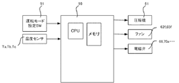
制御装置90は、商品収納庫40a、40b、40cを冷却加熱の設定モードにより冷却もしくは加熱の制御をするものであり、図4の制御ブロック図に示すように内部にCPU、メモリを有し、商品収納庫40a、40b、40cの冷却加熱を設定する冷却加熱モード設定SW91の設定により冷却加熱の制御を行う。そして、制御装置90は、庫内温センサTa、Tb、Tcにより検知した温度が一定温度範囲内となるように、圧縮機61、凝縮器電磁弁68、冷却器入口電磁弁70a、70b、70c、冷却器出口電磁弁72b、72c、加熱器電磁弁68b、68cなどをON・OFF制御するサーモサイクル運転により庫内温度を適温に維持する。
As the refrigerant, a refrigerant used at a critical pressure or lower, for example, a fluorocarbon refrigerant, R134a is used. Moreover, the refrigerant | coolant used above a critical pressure, for example, a carbon dioxide refrigerant, may be sufficient.
The
サーモサイクル運転は、庫内温度がサーモOFF温度(例えば、冷却の場合は−2℃、加熱の場合は61℃)になったときにはその商品収納庫内の庫内熱交換器の出入口側に接続された電磁弁を閉成し、庫内温度がサーモON温度(例えば、冷却の場合は8℃、加熱の場合は41℃)になったときにはその商品収納庫内の庫内熱交換器の出入口側に接続された電磁弁を開成することにより回路内に循環する冷媒の経路を適宜切り替えて、庫内を適温に制御するものである。すなわち、庫内温度とサーモOFF温度、サーモON温度とを比較して、各庫内の運転モードを冷却運転、加熱運転、停止の3つの状態に切り替えてサーモサイクル運転を行う。よって、運転モードの組合せとして、ヒートポンプ運転、冷却単独運転、加熱単独運転がある。
また、制御装置90は、圧縮機61の起動時に冷却器入口電磁弁70a,70b,70c、冷却器出口電磁弁72b、72c、凝縮器電磁弁68、加熱器電磁弁68b、68c、を開成して圧縮機の出入口間の圧力を平衡にする圧力平衡調整制御を有している。
Thermocycle operation is connected to the inlet / outlet side of the internal heat exchanger in the product storage when the internal temperature reaches the thermo OFF temperature (for example, -2 ° C for cooling and 61 ° C for heating) When the temperature inside the chamber reaches the thermo-ON temperature (for example, 8 ° C for cooling and 41 ° C for heating), the inlet / outlet of the internal heat exchanger in the product storage is closed. By opening the solenoid valve connected to the side, the path of the refrigerant circulating in the circuit is appropriately switched to control the interior at an appropriate temperature. That is, the internal temperature, the thermo OFF temperature, and the thermo ON temperature are compared, and the thermocycle operation is performed by switching the operation mode in each chamber to three states of a cooling operation, a heating operation, and a stop. Therefore, there are a heat pump operation, a cooling single operation, and a heating single operation as a combination of operation modes.
The
ここで、冷却加熱モード設定SW91をCCCモードに設定すると、制御装置90は、凝縮器電磁弁68、冷却器入口電磁弁70a、70b、70c、冷却器出口電磁弁72b、72cを開成し、加熱器電磁弁68b、68cを閉止して、圧縮機61を駆動させる。このとき図5の太線で示すように圧縮機61で圧縮された高温冷媒は、凝縮器62にて凝縮され液体となり、膨張器63で膨張して低温の気液二相流となり、分配器64で三方に分流された後庫内熱交換器65a、65b、65cに流入する。流入した冷媒は、庫内熱交換器65a、65b、65cで蒸発し、商品収納庫40a、40b、40cを冷却し、蒸発した冷媒は集合器67で集合して液冷媒を貯留するアキュムレータ69に流入し気液に分離されて気相の冷媒のみ圧縮機61に戻る。なお、この冷却は、制御装置90にて庫内温度センサTa、Tb、Tcによるサーモサイクル運転により庫内温度が適温に制御される。
Here, when the cooling / heating mode setting SW91 is set to the CCC mode, the
また、冷却加熱モード設定SW91をCHHモードに設定すると、制御装置90は、加熱器電磁弁68b、68c、冷却器入口電磁弁70aを開成し、凝縮器電磁弁68、冷却器入口電磁弁70b、70c、冷却器出口電磁弁72b、72cを閉止し、圧縮機61を駆動させる。このとき図6の太線で示す回路内を冷媒が循環し、圧縮機61で圧縮された高温冷媒は、加熱器電磁弁68b、68cを経由して2個の庫内熱交換器65b、65cに流入する。庫内熱交換器65b、65cに流入した冷媒は凝縮し、商品収納庫40b、40cを加熱し、逆止弁71,71を経由して集合し、庫外熱交換器76でさらに凝縮して第2の膨張器79に流入する。膨張器79に流入した冷媒は、膨張して低温低圧の気液二相流となり分配器64、冷却器入口電磁弁70aを経由して庫内熱交換器65aに流入する。庫内熱交換器65aに流入した冷媒は、庫内熱交換器65aで蒸発して商品収納庫40aを冷却し、集合器67、アキュムレータ69を経由して圧縮機61に戻る。このヒートポンプ運転も前述のようにサーモサイクル運転で庫内が適温に維持される。
When the cooling / heating
そして、冷却する商品収納庫がすべてサーモOFF温度に達すると圧縮機61を停止する。やがて、冷却休止中の商品収納庫が適正温度外に到達(サーモON温度に到達)すると、圧縮機61を再起動して、サーモサイクル運転が行われる。このとき、圧縮機61の出入口間の圧力差が高いので、前述の冷却加熱設定モードですべての庫内熱交換器65a、65b、65cが開通する状態となるように冷却器入口電磁弁70a,70b,70c、冷却器出口電磁弁72b、72c、凝縮器電磁弁68、加熱器電磁弁68b、68cを開閉して圧縮機の出入口間の圧力を平衡にする圧力平衡調整制御を行う。この圧力平衡調整制御について、図7のサーモサイクル運転制御の要部フローチャートを参照しつつ、冷却加熱の設定モードがCHHの場合を例にして説明をする。
始めに制御装置90は、温度センサTa、Tb、Tcにより各商品収納庫の温度を検出して(S1)、各収納庫内の温度がサーモ温度に達したか、すなわち、サーモOFF温度に達したか、または、サーモON温度の達したかを判定する(S2)。もし、収納庫の温度がサーモ温度に達していなければ(S2;N)、同一の運転モードを継続して庫内温度の検出(S1)に戻る。収納庫の温度がサーモ温度に達してしていれば(S2;Y)、その状態に対応して庫内の運転モードを変更する(S3)。そして、まず新たな運転モードが冷却庫の運転モードの変更状態を判定する(S4)。
Then, when all the product storages to be cooled reach the thermo OFF temperature, the
First, the
冷却庫の運転モードの変更がなければ(S4;C1)、加熱庫の運転モードが変更されたことになり、次に圧縮機61の運転状態を確認する(S11)。圧縮機61が駆動中であれば(S11;Y)、冷却単独運転もしくは別運転モードのヒートポンプ運転となるので、加熱庫内の庫内熱交換器に関する電磁弁を切替えて(S12)、庫内温度の検出(S1)に戻る。例えば、左庫40aが冷却運転で中庫40b、右庫40cが加熱運転のときに中庫40bがサーモOFF温度になれば、左庫40aが冷却で右庫40cが加熱のヒートポンプ運転のモードとなるので、図8に示すように加熱電磁弁68bを閉止して、図中の太線で示す冷媒回路に冷媒を循環させるヒートポンプ運転を行う。また、圧縮機61が停止中であれば(S11;N)、加熱単独運転から別モードの加熱単独運転もしくは運転停止となるので、当該加熱ヒータの通電を切替えて(S13)、庫内温度の検出(S1)に戻る。
If there is no change in the operation mode of the refrigerator (S4; C1), the operation mode of the heating chamber is changed, and then the operation state of the
また、ステップS4で冷却庫の運転モードが冷却運転から停止となる変更であれば(S4;C2)、ヒートポンプ運転から加熱単独運転への運転モード変更、もしくは、冷却単独運転から運転停止となるので、圧縮機61を停止し(S21)、すべての電磁弁を閉止して(S22)、庫内温度の検出(S1)に戻る。
また、ステップS4で冷却庫の運転モードが停止から冷却運転となる変更であれば(S4;C3)、停止から冷却単独運転の運転モード、もしくは、加熱単独運転からヒートポンプ運転に切替わることになる。そこで、圧縮機61を再起動するためにステップS31〜34に示す圧力平衡制御を行う。すなわち、すべての庫内熱交換器65a,65b,65cが開通するように電磁弁を開成する(S31)。具体的には、冷却加熱の設定モードがCHHであれば、図6に示すように加熱器電磁弁68b、68c、冷却器入口電磁弁70aを開成し、凝縮器電磁弁68、冷却器入口電磁弁70b、70c、冷却器出口電磁弁72b、72cは閉止を維持する。このとき、停止している圧縮機61の出入口部に繋がる冷媒回路が図中の太線部で開通することになり、圧縮機61の出入口部の圧力差が徐々に低減され、圧縮機61の起動が容易になる。この状態を所定時間(例えば、240秒間)継続する(S32;N)。なお、この間でも各商品収納庫40a,40b,40cの庫内温度の検出を行い(S33)、サーモON温度が検出されれば、制御装置90は新たな運転モードを記憶する(S34)。ただし、この圧力平衡調整中に加熱する商品収納庫内の温度がサーモON温度に達したときには加熱単独運転に移行せず新たな運転モードを記憶するのみとする。例えば右庫40cがサーモON温度に達したときには、加熱ヒータ66cを通電することは行わない。
Further, if the operation mode of the refrigerator is changed from the cooling operation to the stop in step S4 (S4; C2), the operation mode change from the heat pump operation to the heating single operation or the cooling single operation is stopped. Then, the
Further, if the operation mode of the refrigerator is changed from the stop to the cooling operation in step S4 (S4; C3), the operation mode is switched from the stop to the cooling single operation mode or from the heating single operation to the heat pump operation. . Therefore, in order to restart the
そして、ステップS32で所定時間が経過すると(S32;Y)、圧力平衡調整制御を終了させ、ステップS34で記憶した新たな運転モードにて電磁弁を設定する(S35)。例えば、圧力平衡調整中に右庫40cがサーモON温度に達したときには、左庫40aを冷却、中庫40bを停止、右庫40cを加熱モードとするヒートポンプ運転のモードとなるので、加熱電磁弁68bを閉止し加熱器電磁弁68b、冷却器入口電磁弁70aを開成維持し、冷却器入口電磁弁70b、70c、凝縮器電磁弁68、冷却器出口電磁弁72b、72cを閉止維持して、圧縮機61を駆動させ(S36)、図8の太線で示す回路にて冷媒を循環させるヒートポンプ運転を行う。なお、圧力平衡調整制御前にヒータが運転されている場合(加熱単独運転となっている場合)には(S37;Y)、圧力平衡調整制御中は加熱ヒータの通電しておき、圧力平衡調整制御後に加熱ヒータを停止して(S38)、ヒートポンプ運転に切替え庫内温度の検出(S1)に戻る。
When a predetermined time elapses in step S32 (S32; Y), the pressure balance adjustment control is terminated, and the solenoid valve is set in the new operation mode stored in step S34 (S35). For example, when the
このように、圧力平衡調整中に加熱する商品収納庫内の温度がサーモON温度に達した場合にも直ちに加熱単独運転に移行せず、圧力平衡調整終了後に運転を再開する制御装置90有することにより、加熱単独運転を低減しヒートポンプ運転を増加させることにより消費電力を低減することができる。
なお、圧力平衡調整中のみ加熱ヒータを停止することも、図7のフローチャートでステップS34とS35の間に加熱ヒータ停止の指令を挿入することが可能で、このことにより、加熱単独運転を低減しヒートポンプ運転を増加させることにより消費電力を低減することができる。
In this way, even when the temperature in the product storage to be heated during the pressure balance adjustment reaches the thermo ON temperature, the
Note that stopping the heater only during pressure balance adjustment can also insert a heater heater stop command between steps S34 and S35 in the flowchart of FIG. 7, which reduces the single heating operation. Power consumption can be reduced by increasing the heat pump operation.
10 本体キャビネット
20 外扉
30 内扉
40a、40b、40c 商品収納庫
60 冷却/加熱ユニット
61 圧縮機
62 凝縮器
63、79 膨張器
64 分流器
65a、65b、65c 庫内熱交換器
66b、66c 加熱ヒータ
68 凝縮器電磁弁
68a、68b 加熱器電磁弁
70a、70b、70c 冷却器入口電磁弁
72b、72c 冷却器出口電磁弁
90 制御装置
91 冷却加熱モード設定SW
DESCRIPTION OF
Claims (1)
冷却加熱兼用の商品収納庫に加熱ヒータを有し、ヒートポンプ運転を行わずに当該加熱ヒータのみで加熱単独運転を行う制御と、
商品収納庫内に温度センサを有し、当該温度センサにより検出した温度と予め設定したサーモON温度、サーモOFF温度とを比較して前記冷却器入口電磁弁、前記冷却器出口電磁弁、前記凝縮器電磁弁、前記加熱器電磁弁の切替、あるいは、加熱ヒータの通電にて複数の商品収納庫の冷却もしくは加熱するサーモサイクル制御と、
前記圧縮機の起動時に前記冷却器入口電磁弁、前記冷却器出口電磁弁、前記加熱器電磁弁を開成して圧縮機の出入口間の圧力を平衡にする圧力平衡調整制御と、を行う制御装置をもってなる自動販売機において、
前記制御装置は圧力平衡調整中に加熱する商品収納庫内の温度がサーモON温度に達した場合にも加熱単独運転に移行せず、圧力平衡調整終了後に運転を再開することを特徴とする自動販売機。 A vending machine that has a plurality of product storages for cooling and heating, and selectively cools or heats the product storages in a cooling / heating setting mode for cooling and heating, and a compressor that compresses the refrigerant, A condenser for condensing the refrigerant via a condenser solenoid valve provided; an expansion means for expanding the refrigerant; a distributor for distributing the refrigerant expanded by the expansion means; and a solenoid inlet solenoid valve from the distributor provided in the warehouse A plurality of in-compartment heat exchangers that evaporate the refrigerant through a merging device that merges the evaporated refrigerant through a cooler outlet electromagnetic valve, and constitutes a cooling circuit, Pipe connection between the internal heat exchanger and the cooler inlet electromagnetic valve from the compressor via a heater electromagnetic valve, and between the internal heat exchanger and the cooler outlet electromagnetic valve The distribution via the external heat exchanger and the second expansion means Pipe by connecting, constitutes a heating-cooling circulation circuit the in-compartment heat exchanger to act as a condenser performs the heat-pump operation, the
Control that has a heater in the product storage that also serves as cooling and heating, and that performs heating only operation with only the heater without performing the heat pump operation,
The product storage has a temperature sensor, and compares the temperature detected by the temperature sensor with the preset thermo ON temperature and thermo OFF temperature, the cooler inlet solenoid valve, the cooler outlet solenoid valve, the condensation Thermocycle control for cooling or heating a plurality of product storage boxes by switching a heater solenoid valve, switching of the heater solenoid valve, or energization of a heater,
A control device that performs pressure balance adjustment control that opens the cooler inlet solenoid valve, the cooler outlet solenoid valve, and the heater solenoid valve to balance the pressure between the compressor inlet and outlet when starting the compressor. In vending machines with
The control device does not shift to the heating independent operation even when the temperature in the product storage to be heated during the pressure balance adjustment reaches the thermo ON temperature, and restarts the operation after the pressure balance adjustment is completed. Vending machine.
Priority Applications (1)
| Application Number | Priority Date | Filing Date | Title |
|---|---|---|---|
| JP2009097072A JP5240030B2 (en) | 2009-04-13 | 2009-04-13 | vending machine |
Applications Claiming Priority (1)
| Application Number | Priority Date | Filing Date | Title |
|---|---|---|---|
| JP2009097072A JP5240030B2 (en) | 2009-04-13 | 2009-04-13 | vending machine |
Publications (2)
| Publication Number | Publication Date |
|---|---|
| JP2010250433A JP2010250433A (en) | 2010-11-04 |
| JP5240030B2 true JP5240030B2 (en) | 2013-07-17 |
Family
ID=43312716
Family Applications (1)
| Application Number | Title | Priority Date | Filing Date |
|---|---|---|---|
| JP2009097072A Active JP5240030B2 (en) | 2009-04-13 | 2009-04-13 | vending machine |
Country Status (1)
| Country | Link |
|---|---|
| JP (1) | JP5240030B2 (en) |
Family Cites Families (4)
| Publication number | Priority date | Publication date | Assignee | Title |
|---|---|---|---|---|
| JP4935077B2 (en) * | 2006-01-06 | 2012-05-23 | 富士電機リテイルシステムズ株式会社 | Refrigerator and vending machine |
| JP5012102B2 (en) * | 2007-03-13 | 2012-08-29 | パナソニック株式会社 | Vending machine control equipment |
| JP2008267700A (en) * | 2007-04-20 | 2008-11-06 | Sanden Corp | Cooling and heating device |
| JP4557010B2 (en) * | 2007-08-30 | 2010-10-06 | 富士電機リテイルシステムズ株式会社 | vending machine |
-
2009
- 2009-04-13 JP JP2009097072A patent/JP5240030B2/en active Active
Also Published As
| Publication number | Publication date |
|---|---|
| JP2010250433A (en) | 2010-11-04 |
Similar Documents
| Publication | Publication Date | Title |
|---|---|---|
| JP4557010B2 (en) | vending machine | |
| JP5169282B2 (en) | vending machine | |
| JP2010079351A (en) | Vending machine | |
| JP5392491B2 (en) | Refrigerant circuit | |
| JP4924535B2 (en) | vending machine | |
| JP5471563B2 (en) | vending machine | |
| JP5321241B2 (en) | vending machine | |
| JP5056426B2 (en) | vending machine | |
| JP5407621B2 (en) | Cooling and heating device | |
| JP5266819B2 (en) | vending machine | |
| JP5240030B2 (en) | vending machine | |
| JP5169383B2 (en) | vending machine | |
| JP2010129014A (en) | Vending machine | |
| JP4911105B2 (en) | vending machine | |
| JP5569634B2 (en) | Operation method of cooling heating device | |
| JP5434423B2 (en) | vending machine | |
| JP2010152673A (en) | Vending machine | |
| JP5229057B2 (en) | vending machine | |
| JP5240016B2 (en) | vending machine | |
| JP5240017B2 (en) | vending machine | |
| JP5056425B2 (en) | vending machine | |
| JP5471518B2 (en) | vending machine | |
| JP4548540B2 (en) | vending machine | |
| JP2011127848A (en) | Refrigerant circuit | |
| JP5407692B2 (en) | vending machine |
Legal Events
| Date | Code | Title | Description |
|---|---|---|---|
| A625 | Written request for application examination (by other person) |
Free format text: JAPANESE INTERMEDIATE CODE: A625 Effective date: 20110812 |
|
| A711 | Notification of change in applicant |
Free format text: JAPANESE INTERMEDIATE CODE: A712 Effective date: 20121025 |
|
| A977 | Report on retrieval |
Free format text: JAPANESE INTERMEDIATE CODE: A971007 Effective date: 20130225 |
|
| TRDD | Decision of grant or rejection written | ||
| A01 | Written decision to grant a patent or to grant a registration (utility model) |
Free format text: JAPANESE INTERMEDIATE CODE: A01 Effective date: 20130305 |
|
| A61 | First payment of annual fees (during grant procedure) |
Free format text: JAPANESE INTERMEDIATE CODE: A61 Effective date: 20130318 |
|
| FPAY | Renewal fee payment (event date is renewal date of database) |
Free format text: PAYMENT UNTIL: 20160412 Year of fee payment: 3 |
|
| R150 | Certificate of patent or registration of utility model |
Free format text: JAPANESE INTERMEDIATE CODE: R150 Ref document number: 5240030 Country of ref document: JP Free format text: JAPANESE INTERMEDIATE CODE: R150 |
|
| R250 | Receipt of annual fees |
Free format text: JAPANESE INTERMEDIATE CODE: R250 |
|
| R250 | Receipt of annual fees |
Free format text: JAPANESE INTERMEDIATE CODE: R250 |
|
| R250 | Receipt of annual fees |
Free format text: JAPANESE INTERMEDIATE CODE: R250 |
|
| R250 | Receipt of annual fees |
Free format text: JAPANESE INTERMEDIATE CODE: R250 |
|
| R250 | Receipt of annual fees |
Free format text: JAPANESE INTERMEDIATE CODE: R250 |
|
| R250 | Receipt of annual fees |
Free format text: JAPANESE INTERMEDIATE CODE: R250 |
|
| R250 | Receipt of annual fees |
Free format text: JAPANESE INTERMEDIATE CODE: R250 |
|
| R250 | Receipt of annual fees |
Free format text: JAPANESE INTERMEDIATE CODE: R250 |