JP5236471B2 - Stiffeners, baffles and seals with malleable carriers - Google Patents
Stiffeners, baffles and seals with malleable carriers Download PDFInfo
- Publication number
- JP5236471B2 JP5236471B2 JP2008525233A JP2008525233A JP5236471B2 JP 5236471 B2 JP5236471 B2 JP 5236471B2 JP 2008525233 A JP2008525233 A JP 2008525233A JP 2008525233 A JP2008525233 A JP 2008525233A JP 5236471 B2 JP5236471 B2 JP 5236471B2
- Authority
- JP
- Japan
- Prior art keywords
- carrier
- malleable
- activatable material
- malleable carrier
- activatable
- Prior art date
- Legal status (The legal status is an assumption and is not a legal conclusion. Google has not performed a legal analysis and makes no representation as to the accuracy of the status listed.)
- Expired - Fee Related
Links
Images


Classifications
-
- B—PERFORMING OPERATIONS; TRANSPORTING
- B29—WORKING OF PLASTICS; WORKING OF SUBSTANCES IN A PLASTIC STATE IN GENERAL
- B29C—SHAPING OR JOINING OF PLASTICS; SHAPING OF MATERIAL IN A PLASTIC STATE, NOT OTHERWISE PROVIDED FOR; AFTER-TREATMENT OF THE SHAPED PRODUCTS, e.g. REPAIRING
- B29C70/00—Shaping composites, i.e. plastics material comprising reinforcements, fillers or preformed parts, e.g. inserts
- B29C70/88—Shaping composites, i.e. plastics material comprising reinforcements, fillers or preformed parts, e.g. inserts characterised primarily by possessing specific properties, e.g. electrically conductive or locally reinforced
-
- B—PERFORMING OPERATIONS; TRANSPORTING
- B29—WORKING OF PLASTICS; WORKING OF SUBSTANCES IN A PLASTIC STATE IN GENERAL
- B29C—SHAPING OR JOINING OF PLASTICS; SHAPING OF MATERIAL IN A PLASTIC STATE, NOT OTHERWISE PROVIDED FOR; AFTER-TREATMENT OF THE SHAPED PRODUCTS, e.g. REPAIRING
- B29C44/00—Shaping by internal pressure generated in the material, e.g. swelling or foaming ; Producing porous or cellular expanded plastics articles
- B29C44/02—Shaping by internal pressure generated in the material, e.g. swelling or foaming ; Producing porous or cellular expanded plastics articles for articles of definite length, i.e. discrete articles
- B29C44/12—Incorporating or moulding on preformed parts, e.g. inserts or reinforcements
- B29C44/18—Filling preformed cavities
-
- B—PERFORMING OPERATIONS; TRANSPORTING
- B29—WORKING OF PLASTICS; WORKING OF SUBSTANCES IN A PLASTIC STATE IN GENERAL
- B29C—SHAPING OR JOINING OF PLASTICS; SHAPING OF MATERIAL IN A PLASTIC STATE, NOT OTHERWISE PROVIDED FOR; AFTER-TREATMENT OF THE SHAPED PRODUCTS, e.g. REPAIRING
- B29C70/00—Shaping composites, i.e. plastics material comprising reinforcements, fillers or preformed parts, e.g. inserts
- B29C70/68—Shaping composites, i.e. plastics material comprising reinforcements, fillers or preformed parts, e.g. inserts by incorporating or moulding on preformed parts, e.g. inserts or layers, e.g. foam blocks
- B29C70/688—Shaping composites, i.e. plastics material comprising reinforcements, fillers or preformed parts, e.g. inserts by incorporating or moulding on preformed parts, e.g. inserts or layers, e.g. foam blocks the inserts being meshes or lattices
-
- B—PERFORMING OPERATIONS; TRANSPORTING
- B29—WORKING OF PLASTICS; WORKING OF SUBSTANCES IN A PLASTIC STATE IN GENERAL
- B29C—SHAPING OR JOINING OF PLASTICS; SHAPING OF MATERIAL IN A PLASTIC STATE, NOT OTHERWISE PROVIDED FOR; AFTER-TREATMENT OF THE SHAPED PRODUCTS, e.g. REPAIRING
- B29C70/00—Shaping composites, i.e. plastics material comprising reinforcements, fillers or preformed parts, e.g. inserts
- B29C70/68—Shaping composites, i.e. plastics material comprising reinforcements, fillers or preformed parts, e.g. inserts by incorporating or moulding on preformed parts, e.g. inserts or layers, e.g. foam blocks
- B29C70/72—Encapsulating inserts having non-encapsulated projections, e.g. extremities or terminal portions of electrical components
-
- B—PERFORMING OPERATIONS; TRANSPORTING
- B62—LAND VEHICLES FOR TRAVELLING OTHERWISE THAN ON RAILS
- B62D—MOTOR VEHICLES; TRAILERS
- B62D29/00—Superstructures, understructures, or sub-units thereof, characterised by the material thereof
- B62D29/001—Superstructures, understructures, or sub-units thereof, characterised by the material thereof characterised by combining metal and synthetic material
- B62D29/002—Superstructures, understructures, or sub-units thereof, characterised by the material thereof characterised by combining metal and synthetic material a foamable synthetic material or metal being added in situ
-
- B—PERFORMING OPERATIONS; TRANSPORTING
- B29—WORKING OF PLASTICS; WORKING OF SUBSTANCES IN A PLASTIC STATE IN GENERAL
- B29L—INDEXING SCHEME ASSOCIATED WITH SUBCLASS B29C, RELATING TO PARTICULAR ARTICLES
- B29L2031/00—Other particular articles
- B29L2031/30—Vehicles, e.g. ships or aircraft, or body parts thereof
-
- H—ELECTRICITY
- H01—ELECTRIC ELEMENTS
- H01L—SEMICONDUCTOR DEVICES NOT COVERED BY CLASS H10
- H01L2924/00—Indexing scheme for arrangements or methods for connecting or disconnecting semiconductor or solid-state bodies as covered by H01L24/00
- H01L2924/0001—Technical content checked by a classifier
- H01L2924/0002—Not covered by any one of groups H01L24/00, H01L24/00 and H01L2224/00
-
- Y—GENERAL TAGGING OF NEW TECHNOLOGICAL DEVELOPMENTS; GENERAL TAGGING OF CROSS-SECTIONAL TECHNOLOGIES SPANNING OVER SEVERAL SECTIONS OF THE IPC; TECHNICAL SUBJECTS COVERED BY FORMER USPC CROSS-REFERENCE ART COLLECTIONS [XRACs] AND DIGESTS
- Y10—TECHNICAL SUBJECTS COVERED BY FORMER USPC
- Y10T—TECHNICAL SUBJECTS COVERED BY FORMER US CLASSIFICATION
- Y10T29/00—Metal working
- Y10T29/49—Method of mechanical manufacture
- Y10T29/49616—Structural member making
- Y10T29/49622—Vehicular structural member making
-
- Y—GENERAL TAGGING OF NEW TECHNOLOGICAL DEVELOPMENTS; GENERAL TAGGING OF CROSS-SECTIONAL TECHNOLOGIES SPANNING OVER SEVERAL SECTIONS OF THE IPC; TECHNICAL SUBJECTS COVERED BY FORMER USPC CROSS-REFERENCE ART COLLECTIONS [XRACs] AND DIGESTS
- Y10—TECHNICAL SUBJECTS COVERED BY FORMER USPC
- Y10T—TECHNICAL SUBJECTS COVERED BY FORMER US CLASSIFICATION
- Y10T29/00—Metal working
- Y10T29/49—Method of mechanical manufacture
- Y10T29/4998—Combined manufacture including applying or shaping of fluent material
Landscapes
- Engineering & Computer Science (AREA)
- Chemical & Material Sciences (AREA)
- Mechanical Engineering (AREA)
- Composite Materials (AREA)
- Combustion & Propulsion (AREA)
- Structural Engineering (AREA)
- Architecture (AREA)
- Transportation (AREA)
- Body Structure For Vehicles (AREA)
- Injection Moulding Of Plastics Or The Like (AREA)
- Extrusion Moulding Of Plastics Or The Like (AREA)
- Casting Or Compression Moulding Of Plastics Or The Like (AREA)
- Vehicle Interior And Exterior Ornaments, Soundproofing, And Insulation (AREA)
- Gasket Seals (AREA)
- Connection Of Plates (AREA)
Description
本発明は、概略的には、シール、バッフル、補強又はこれらの組合せを、製品、例えば自動車に提供する部材に関する。 The present invention relates generally to members that provide seals, baffles, reinforcements, or combinations thereof to a product, such as an automobile.
なお、本願は、2005年8月4日に出願された米国仮特許出願第60/705,561号及び2006年8月1日に出願された米国特許出願(願番未付与、代理人事件番号1001−218)の出願日に関する権利を主張する出願であり、これら両方の特許出願を参照により引用し、全ての目的に関しその記載内容を本明細書の一部とする。 The present application is based on U.S. Provisional Patent Application No. 60 / 705,561 filed on August 4, 2005 and U.S. Patent Application filed on August 1, 2006 (application number not assigned, agent case number). 1001-218), both of which are hereby incorporated by reference, and are incorporated herein by reference for all purposes.
長年にわたり、産業界、特に輸送業界は、バッフル、シール、構造的補強等を製品、例えば自動車に提供する部材の設計に関心がある。一例として、米国特許第5,755,486号明細書、同第4,901,500号明細書及び同第4,751,249号明細書は、先行技術の装置を記載している。一般に、かかる部材は、活性化可能な材料が被着されたキャリヤを有する。かかる部材の設計には、種々の要因が含まれる場合があり、これら要因は、互いに逆効果である場合がある。例えば、一般的には、かかる部材は、比較的安価であることが望ましい。 Over the years, the industry, especially the transportation industry, has been interested in the design of components that provide baffles, seals, structural reinforcement, etc. to products such as automobiles. As an example, US Pat. Nos. 5,755,486, 4,901,500 and 4,751,249 describe prior art devices. In general, such members have a carrier on which an activatable material is deposited. The design of such a member may include various factors, which may be counterproductive to each other. For example, in general, it is desirable for such a member to be relatively inexpensive.
しかしながら、かかる部材の材料費及び加工費は、特に1つ又は2つ以上の輪郭を有するように部材を成形することが望ましい場合、コストを押し上げる場合がある。本発明は、互いに競合する設計上の要因に効果的に対処し又は以下の説明から明らかになる他の利点をもたらす、補強、バッフル又はシールを提供する部材を提供する。 However, the material and processing costs of such members can increase costs, especially if it is desirable to shape the member to have one or more contours. The present invention provides a member that provides a reinforcement, baffle or seal that effectively addresses competing design factors or provides other advantages that will become apparent from the following description.
本発明は、シール、バッフル、補強又はこれら作用の組合せを製品、例えば自動車に提供する方法に関する。この方法によれば、展性キャリヤを用意し、活性化可能な材料を展性キャリヤに関連させ、それにより部材を形成する。好ましくは、活性化可能な材料の体積は、展性キャリヤの体積の少なくとも500%である。また、展性キャリヤ又は活性化可能材料若しくはこれら両方を本方法に従って成形し、この成形ステップは、代表的には、次のステップ、即ち、1)展性キャリヤを所定の形態に合わせて成形し、活性化可能材料を展性キャリヤ上にモールディングするステップ、2)活性化可能材料を展性キャリヤ上にモールディングして部材を形成し、部材を展性キャリヤ及び活性化可能材料の成形を含むやり方で物品の構造体に取り付けるステップ、又は、3)活性化可能材料を展性キャリヤに被着させ、展性キャリヤの少なくとも一部分を曲げて展性キャリヤ及び活性化可能材料を構造体に取り付けるステップのうち少なくとも1つのステップ又はこれらステップの組合せを含む。 The present invention relates to a method of providing a seal, baffle, reinforcement or a combination of these actions to a product, such as an automobile. According to this method, a malleable carrier is provided and an activatable material is associated with the malleable carrier, thereby forming a member. Preferably the volume of activatable material is at least 500% of the volume of the malleable carrier. Also, the malleable carrier and / or activatable material is shaped according to the present method, which typically comprises the following steps: 1) shaping the malleable carrier to a predetermined shape. Molding the activatable material onto the malleable carrier, 2) molding the activatable material onto the malleable carrier to form a member, the method comprising forming the member into the malleable carrier and the activatable material Attaching the activatable material to the malleable carrier and bending at least a portion of the malleable carrier to attach the malleable carrier and activatable material to the structure. At least one step or a combination of these steps is included.
本発明の特徴及び新規事項は、以下の詳細な説明、特許請求の範囲及び図面を参照すると、一層明らかになる。 The features and novelty of the present invention will become more apparent with reference to the following detailed description, claims and drawings.
本発明は、シール、バッフル、補強又はこれら作用の組合せを製品の1つ又は2つ以上の構造体に提供するのに適した部材及びこの部材を形成し、この部材を製品の1つ又は2つ以上の構造体に被着させる方法の提供に関する。1つ又は2つ以上の構造体とかかる部材は、一緒になって、この部材により提供される機能的属性(例えば、騒音軽減、密封、強度、これらの組合せ等)に鑑みて、製品にとって全体として望ましいシステム又は組立体を形成する。部材を種々の製品、例えば船、列車、建物、電化製品、住居、家具等の種々の構造体と関連して利用できることが想定される。しかしながら、かかる部材は、輸送車両、例えば自動車の構造体又は組立体への利用に特に適していることが判明した。一般に、かかる部材を自動車の種々の構造体、例えば自動車の車体、フレーム、エンジン、ボンネット、トランク、バンパ、これらの組合せ等に取り付けるのが良いことが想定される。 The present invention forms a member suitable for providing a seal, baffle, reinforcement or a combination of these actions to one or more structures of the product and the member, which member is one or two of the product. It relates to the provision of a method for depositing on one or more structures. One or more structures and such members are combined together for the product in view of the functional attributes provided by the member (eg, noise reduction, sealing, strength, combinations thereof, etc.) Forming a desirable system or assembly. It is envisioned that the member can be utilized in connection with various products, such as various structures such as ships, trains, buildings, appliances, residences, furniture and the like. However, it has been found that such components are particularly suitable for use in transport vehicles such as automobile structures or assemblies. In general, it is envisaged that such a member may be attached to various structures of an automobile, such as an automobile body, a frame, an engine, a bonnet, a trunk, a bumper, and combinations thereof.
部材は、代表的には、次のもの、即ち
i)展性キャリヤ、
ii)展性キャリヤに被着された活性化可能な材料、及び
iii)オプションとして、キャリヤ又は活性化可能材料若しくはこれら両方に連結された1つ又は2つ以上のファスナのうち1つ又は2つ以上を含む。
The member is typically: i) a malleable carrier,
ii) an activatable material applied to the malleable carrier, and iii) optionally one or two of one or more fasteners coupled to the carrier and / or activatable material. Including the above.
部材を形成する方法は、代表的には、次のステップ、即ち
i)展性キャリヤを用意するステップ
ii)活性化可能材料を展性キャリヤに関連させるステップ、
iii)活性化可能材料、又は展性キャリヤ材料若しくはこれら両方を成形するステップ、及び
iv)オプションとして、1つ又は2つ以上のファスナを活性化可能材料、又は展性キャリヤ若しくはこれら両方に連結するステップのうち1つ又は2つ以上を含む。
The method of forming the member typically includes the following steps: i) providing a malleable carrier ii) associating an activatable material with the malleable carrier;
iii) molding the activatable material or the malleable carrier material or both; and iv) optionally connecting one or more fasteners to the activatable material or the malleable carrier or both. Includes one or more of the steps.
本明細書においてキャリヤについて用いられる「展性」という用語は、一般に、キャリヤを成形し又は形成することができる程度の柔軟性をそのキャリヤが備えていることを意味する。本発明による展性のある材料は、約1000MPa以下であるが、これよりも大きくても良く、一般的には約700MPa以下、より一般的には約500MPa以下、更により一般的には約350MPa以下であるが、一般的には約10MPaよりも大きいが、これよりも小さくても良く、一般的には約70MPa以下、より一般的には約100MPa以上、更により一般的には約250MPa以上の降伏応力を有する。 The term “malleability” as used herein for a carrier generally means that the carrier is flexible enough to shape or form the carrier. The malleable material according to the present invention is about 1000 MPa or less, but may be larger, generally about 700 MPa or less, more typically about 500 MPa or less, and even more typically about 350 MPa. Or less, but generally greater than about 10 MPa, but may be smaller, generally about 70 MPa or less, more typically about 100 MPa or more, and even more typically about 250 MPa or more. Yield stress of
適当な展性キャリヤ材料としては、ポリマー材料(例えばエラストマー、プラスチック等)、金属、複合材料、繊維状材料、これらの組合せ等が挙げられるが、これらには限定されない。1種類又は2種類以上の金属を含み又は実質的に全体が1種類又は2種類以上の金属で構成された材料が、キャリヤ材料として用いるのに特に適している。例示の金属としては、アルミニウム、鋼、鉄、マグネシウム、亜鉛、鉛、錫、チタン、モリブデン、バナジウム、ジルコニウム、クロム、銅、タングステン、ニッケル、銀、金、白金、これらの組合せ等が挙げられるが、これらには限定されない。 Suitable malleable carrier materials include, but are not limited to, polymeric materials (eg, elastomers, plastics, etc.), metals, composite materials, fibrous materials, combinations thereof, and the like. Particularly suitable for use as a carrier material are materials that contain one or more metals or are substantially entirely composed of one or more metals. Exemplary metals include aluminum, steel, iron, magnesium, zinc, lead, tin, titanium, molybdenum, vanadium, zirconium, chromium, copper, tungsten, nickel, silver, gold, platinum, combinations thereof, and the like. However, it is not limited to these.
一般に、展性キャリヤは、種々の形態に形成できる。一実施形態では、キャリヤは、展性材料の1本又は2本以上のストリップで形成される。本明細書で言及される材料のストリップは、伸長長さ及び最大直径を有し、最大直径が伸長長さよりも実質的に小さい材料の任意の形態である。例えば、最大直径は、伸長長さの20%未満、一般的には10%未満、より一般的には2%未満、更により一般的には0.5%未満であるべきである。伸長長さは、ストリップを実質的に直線の状態に配置したときのストリップの長さであり、最大直径は、長さに実質的に垂直なストリップの最大寸法である。かくして、例えば、コイル状円筒形ワイヤは、ワイヤを広げて実質的に直線の状態に配置した場合、ストリップであると考えることができ、ワイヤの最大直径は、伸長長さよりも実質的に小さい。例示のストリップとしては、ワイヤ、コイル、ストラップ、これらの組合せ等が挙げられる。 In general, malleable carriers can be formed in a variety of forms. In one embodiment, the carrier is formed of one or more strips of malleable material. The strip of material referred to herein is any form of material having an elongated length and a maximum diameter, the maximum diameter being substantially less than the elongated length. For example, the maximum diameter should be less than 20% of the stretch length, typically less than 10%, more typically less than 2%, and even more typically less than 0.5%. The stretch length is the length of the strip when the strip is placed in a substantially straight state, and the maximum diameter is the maximum dimension of the strip that is substantially perpendicular to the length. Thus, for example, a coiled cylindrical wire can be considered a strip when the wire is unrolled and placed in a substantially straight state, with the maximum diameter of the wire being substantially smaller than the stretched length. Exemplary strips include wires, coils, straps, combinations thereof, and the like.
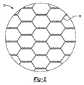
図1〜図3を参照すると、本発明に用いるのに適した適当なキャリヤ材料10,12,14の例が図示されている。これら材料は各々、材料10,12,14を形成するよう互いに撚り合わされた(例えば織編された)複数本(例えば、2本、3本、4本、5本又は6本以上)のストリップ18から成る。図2のキャリヤ材料12は、ハニカム構造の状態に形成された複数本のストリップ18(例えばワイヤ)から成る。さらに、図3のキャリヤ材料14は、比較的大きな開口部20及び比較的小さな開口部22を形成するよう配置された複数本のストリップ18(例えばワイヤ)から成る。一般に、ワイヤメッシュ及び特に金属又はプラスチックワイヤメッシュ製品をキャリヤ材料として採用するのが良い。
1-3, examples of
本発明の部材を形成するため、代表的には、活性化可能な材料をキャリヤ材料に関連させる(例えば、連結、被着、包囲等を行わせる)。キャリヤ材料は、活性化可能材料をキャリヤ材料に関連させる前又は後にキャリヤの状態に形成するのが良い。例えば、キャリヤ材料を切断して所望の形状のキャリヤを形成するのが良く、しかる後、活性化可能材料をキャリヤに関連させるのが良い。変形例として、活性化可能材料をキャリヤ材料に関連させ、次に、キャリヤ材料を切断し又は違ったやり方で形成してキャリヤを形成するのが良い。 To form the members of the present invention, typically an activatable material is associated with the carrier material (eg, coupled, deposited, enclosed, etc.). The carrier material may be formed in the carrier state before or after associating the activatable material with the carrier material. For example, the carrier material may be cut to form the desired shaped carrier, after which the activatable material may be associated with the carrier. Alternatively, the activatable material may be associated with the carrier material, and then the carrier material may be cut or otherwise formed to form the carrier.
本発明に関して用いられる「活性化可能(な)材料」という用語は、所与の条件にさらされると、硬化し(例えば熱硬化し)、膨張し(例えば発泡し)、軟化し、流動化し又はこれらの組合せを生じるよう活性化可能な材料を意味するようになっている。かくして、本発明に関し、別段の言及がなければ、活性化可能材料を上述の動作のうちの1つだけ又は上述の動作の任意の組合せを行うよう活性化できることが想定される。 As used in connection with the present invention, the term “activatable material” refers to curing (eg, thermosetting), expanding (eg, foaming), softening, fluidizing, or when exposed to given conditions. It is intended to mean a material that can be activated to produce these combinations. Thus, with respect to the present invention, unless otherwise stated, it is envisioned that the activatable material can be activated to perform only one of the above operations or any combination of the above operations.
本発明の部材について種々の活性化可能材料を使用することができる。一実施形態では、活性化可能材料を熱活性化材料で形成するのが良く、かかる材料は、熱にさらされると、流動化、硬化(例えば熱硬化)、膨張(例えば発泡)又はこれらの組合せを生じることができる。活性化可能材料は、一般に、触った感じが乾燥状態であって実質的に非粘着性であるのが良く、又は、粘着性であっても良く、いずれの場合においても、かかる材料を所望のパターン、所望の配置状態又は所望の厚さの任意の形態に成形することができ、かかる材料は、実質的に一様な厚さ又は可変厚さを有することができる。例示の膨張性又は発泡性の材料としては、ミシガン州ロメオ所在のエル・アンド・エル・プロダクツ・インコーポレイテッド(L&L Products, Inc.)を介して入手できるL−7102及びL−7220フォームが挙げられる。別の例示の膨張性又は発泡性材料は、2004年6月15日に出願された米国特許出願第10/867,835号明細書(発明の名称:Expandable Material)に開示されている。なお、この米国特許出願を参照により引用し、全ての目的についてその記載内容を本明細書の一部とする。 Various activatable materials can be used for the members of the present invention. In one embodiment, the activatable material may be formed of a heat-activatable material that, when exposed to heat, fluidizes, cures (eg, thermoset), expands (eg, foams), or combinations thereof Can result. The activatable material generally has a dry feel and is substantially non-tacky, or may be tacky, in which case the desired material is It can be shaped into any form of pattern, desired arrangement, or desired thickness, and such materials can have a substantially uniform thickness or variable thickness. Exemplary expandable or foamable materials include L-7102 and L-7220 foams available through L & L Products, Inc., Romeo, Michigan. . Another exemplary expandable or expandable material is disclosed in US patent application Ser. No. 10 / 867,835, filed Jun. 15, 2004 (Expandable Material). It should be noted that this US patent application is cited by reference, and the description is made a part of this specification for all purposes.
他の熱活性化材料の使用が可能であるが、好ましい熱活性化材料は、発泡性ポリマー又はプラスチックであり、好ましくは、発泡性の材料である。特に好ましい材料は、構造的作用、シール、バッフル、音響作用又はこれら作用の組合せを提供することができるEPDM、エラストマー、エポキシ樹脂、アクリレート、アセテート、これらの組合せ等を含む又はこれらを主成分とする発泡性又は密封性の材料である。例えば、フォームは、αオレフィンを含むのが良いエチレンコポリマー又はターポリマーを含むエポキシ系材料であるのが良いが、これには限定されない。コポリマー又はターポリマーとして、ポリマーは、互いに類似した分子と結合できる高い化学的反応性を備えた2種類又は3種類の互いに異なるモノマー、即ち小分子で構成される。 Although other heat activated materials can be used, the preferred heat activated material is a foamable polymer or plastic, preferably a foamable material. Particularly preferred materials include or are based on EPDM, elastomers, epoxy resins, acrylates, acetates, combinations thereof, etc. that can provide structural action, seals, baffles, acoustic action or combinations of these actions. It is a foaming or sealing material. For example, the foam may be, but is not limited to, an epoxy-based material that includes an ethylene copolymer or terpolymer that may include an alpha olefin. As a copolymer or terpolymer, the polymer is composed of two or three different monomers, i.e. small molecules, with high chemical reactivity that can bind to molecules that are similar to each other.
多くのシール、バッフル又は音響作用フォームが、当該技術分野において知られており、本発明に利用できる。代表的なフォームとしては、適当な成分(代表的には、発泡硬化剤)と化合した場合、熱を受けると又は特定の周囲条件の発生時に、確実且つ予測可能なやり方で膨張して硬化するポリマーを主成分とする材料、例えばエポキシ樹脂又はエチレンを主成分とするポリマー(例えばEMA、EVA等)が挙げられる。熱的活性化材料に関する化学的観点からは、フォームは、まず最初に流動性、熱可塑性及び(又は)熱硬化性材料として処理されるのが通例である。代表的には、この材料は、硬化時に架橋し(例えば熱硬化し)、それにより、材料は、それ以上流動できなくなる。 Many seals, baffles or acoustic working foams are known in the art and can be utilized in the present invention. Typical foams, when combined with the appropriate ingredients (typically foam curing agents), expand and cure in a reliable and predictable manner when subjected to heat or when certain ambient conditions occur. Examples thereof include materials containing a polymer as a main component, for example, an epoxy resin or a polymer containing ethylene as a main component (for example, EMA, EVA, etc.). From a chemical point of view for thermally activated materials, the foam is usually first treated as a flowable, thermoplastic and / or thermoset material. Typically, this material crosslinks (eg, thermosets) upon curing, thereby preventing the material from flowing any further.
先行技術の材料と比較した場合の、好ましい発泡性の又は活性化可能な材料の一利点は、好ましい材料を幾つかのやり方で処理できるということにある。好ましい材料は、射出成形、押出し、圧縮成形により又は小型アプリケータを用いて処理できる。これにより、大抵の先行技術の部品の性能を超える設計の部品の形成及び創成が可能になる。 One advantage of the preferred foamable or activatable material compared to prior art materials is that the preferred material can be processed in several ways. Preferred materials can be processed by injection molding, extrusion, compression molding or using a small applicator. This allows the creation and creation of parts with designs that exceed the performance of most prior art parts.
好ましい材料を開示したが、他の材料も使用でき、特に、周囲条件(例えば水分、圧力、時間、化学反応等)により熱活性化され又は違ったやり方で活性化され、選択された用途に適した条件下で予測可能に且つ確実に硬化する材料を使用できる。当然のことながら、かかる材料は、非硬化性材料、非膨張性材料等で形成されても良い。かくして、活性時、材料は、軟化するのが良く、硬化するのが良く、膨張するのが良く、軟化して硬化するだけであるのが良く、硬化するだけであるのが良く、軟化するだけであるのが良く、或いは、活性化不能であっても良い。 Although preferred materials have been disclosed, other materials can be used, especially those that are thermally activated or otherwise activated by ambient conditions (eg, moisture, pressure, time, chemical reactions, etc.) and are suitable for the chosen application Materials that cure predictably and reliably under certain conditions. Of course, such materials may be formed of non-curable materials, non-expandable materials, and the like. Thus, when active, the material should soften, harden, expand well, only soften and harden, only harden, only soften Or may not be activated.
膨張性材料の一例は、米国特許第6,131,897号明細書に開示されたエポキシ系樹脂材料であり、この米国特許を参照により引用し、その教示を本明細書の一部とする。他の考えられる幾つかの材料としては、ポリオレフィン材料、高いガラス転移温度をもつ少なくとも1つのモノマータイプのαオレフィン、フェノール/ホルムアルデヒド材料、フェノキシ材料、ポリウレタン材料を含むコポリマー及びターポリマーが挙げられるが、これらには限定されない。これについては、米国特許第5,766,719号明細書、同第5,755,486号明細書、同第5,575,526号明細書、及び同第5,932,680号明細書も参照されたい(これら米国特許の各々を参照により引用し、その開示内容を本明細書の一部とする)。ブロックトイソシアネートを含むポリウレタン材料も使用できる。一般に、材料の望ましい特徴としては、ガラス転移温度が高いこと(代表的には摂氏70度よりも高い温度)及び付着耐久性が高いことが挙げられる。このように、材料は、一般に、自動車製造業者により採用されている材料系にとって邪魔になることはない。 An example of an intumescent material is the epoxy-based resin material disclosed in US Pat. No. 6,131,897, which is incorporated herein by reference, the teachings of which are incorporated herein. Some other possible materials include polyolefin materials, at least one monomer type alpha olefin with high glass transition temperature, phenol / formaldehyde materials, phenoxy materials, copolymers and terpolymers including polyurethane materials, It is not limited to these. In this regard, U.S. Pat. Nos. 5,766,719, 5,755,486, 5,575,526, and 5,932,680 are also included. Reference is made to each of these U.S. patents, the disclosure of which is incorporated herein by reference. Polyurethane materials containing blocked isocyanates can also be used. In general, desirable characteristics of the material include a high glass transition temperature (typically a temperature higher than 70 degrees Celsius) and high adhesion durability. In this way, the material generally does not interfere with the material system employed by the automobile manufacturer.
他の例示の膨張性材料としては、以下の材料、即ち、エポキシ樹脂、ポリスチレン、スチレンブタジエンスチレン(SBS)ブロックコポリマー、ブタジエンアクリロニトリルゴム、非晶質シリカ、ガラス微小球体、アゾジカーボンアミド、ウレア、ジシアンジアミドのうちの2つ又は3つ以上の組合せが挙げられる。かかる材料の例は、SIKAELASTOMER、SIKAREINFORCER及びSIKABAFFLEという商品名で販売されており、ミシガン州マジソンハイツ所在のサイカ・コーポレイション(Sika Corporation)から市販されている。 Other exemplary intumescent materials include the following materials: epoxy resin, polystyrene, styrene butadiene styrene (SBS) block copolymer, butadiene acrylonitrile rubber, amorphous silica, glass microspheres, azodicarbonamide, urea, A combination of two or more of dicyandiamide is mentioned. Examples of such materials are sold under the trade names SIKAELASTOMER, SIKAREINFORCER and SIKABAFFLE, and are commercially available from Sika Corporation, Madison Heights, Michigan.
材料が熱活性化熱膨張性材料である用途では、フォームを含む材料の選択及び形成に関する重要な検討事項は、材料反応又は材料膨張及び場合によっては硬化が起こる温度である。代表的には、高い処理温度、例えば、フォームが自動車用部品と一緒に高い温度で又は加えられた高いエネルギーレベルで、例えば、塗装、プライマ又はイーコート(e-coat)ベーキング又は硬化ステップの際、処理される場合に自動車組立て工場で遭遇する高い処理温度で反応性になる。自動車組立て作業で遭遇する温度は、約148.89℃〜204.44℃(約300°F〜400°F)の場合があるが、車体及び塗装ショップ用途は、一般に、約93.33℃(約200°F)又はこれよりも僅かに高い温度状態にある。必要ならば、発泡剤用活性剤を配合物中に混ぜ込んで上述の範囲を超える種々の温度状態での膨張を生じさせるのが良い。一般に、適当な膨張性又は発泡性フォームは、約0パーセントから100パーセントを超える範囲の体積膨張(例えば、材料の元々の非膨張状態の体積の50%以上、100%以上、200%以上又は500%以上の体積膨張)を示す。 In applications where the material is a thermally activated thermally expandable material, an important consideration regarding the selection and formation of materials, including foams, is the temperature at which material reaction or material expansion and possibly curing occurs. Typically, at high processing temperatures, such as at high temperatures where the foam is added with or added to automotive parts, or at high energy levels, such as during a paint, primer or e-coat baking or curing step. When processed, it becomes reactive at the high processing temperatures encountered in automobile assembly plants. The temperatures encountered in automobile assembly operations can be about 148.89 ° C. to 204.44 ° C. (about 300 ° F. to 400 ° F.), but car body and paint shop applications are typically about 93.33 ° C. ( About 200 ° F.) or slightly above. If necessary, a blowing agent activator may be incorporated into the formulation to cause expansion at various temperature conditions beyond the above range. In general, suitable expandable or expandable foams have a volume expansion in the range of about 0 percent to more than 100 percent (eg, 50% or more, 100% or more, 200% or more or 500% or more of the original unexpanded volume of the material). % Volume expansion).
材料又は媒体は、バッフル技術の利用、当該技術分野において周知の教示によるダイカスト応用技術の利用、バッフル及びブラダ(袋)システムの使用を含むのが良い圧送型被着システムの利用及び吹付け型応用技術の利用により金型に沿って配置された減衰特性を備える活性ポリマー又は他の熱活性化ポリマー(例えば、発泡性ホットメルト接着剤系ポリマー又は膨張可能構造的フォーム、これらの例としては、オレフィン系ポリマー、ビニルポリマー、熱可塑性ゴム含有ポリマー、エポキシ、ウレタン等が挙げられる)で少なくとも部分的に被覆されるのが良い。 The material or media may include the use of baffle technology, the use of die casting applications according to teachings well known in the art, the use of baffle and bladder systems, and the use of pressure-fed deposition systems and spray-type applications. Activated polymers or other heat-activated polymers with damping properties placed along the mold through the use of technology (eg, foamable hot melt adhesive-based polymers or expandable structural foams, examples of which include olefins A polymer, a vinyl polymer, a thermoplastic rubber-containing polymer, an epoxy, a urethane, etc.).
形成
一般に、本発明の部材の形成は、多種多様な技術、例えば押出し、モールディング(例えば圧縮成形、射出成形、吹き込み成形等)、機械加工、これらの組合せ等を用いて達成できる。かかる形成では、一般に、一塊又は二塊の活性化可能材料をキャリヤ及び(又は)キャリヤ材料に関連させる。活性化可能材料をキャリヤに直接又は間接的に連結し又は取り付けることができる。しかしながら、代表的には、活性化可能材料をキャリヤの大部分の周りに配置する(即ち、前者が後者を包囲する)。かかる実施形態では、一般に、活性化可能材料がキャリヤの少なくとも30%であるが、場合によってはこれよりも少なくても良く、一般的には少なくとも50%、より一般的には少なくとも80%、更により一般的には少なくとも90%、或いは場合によっては100%包囲することが望ましい。
Formation In general, formation of the members of the present invention can be accomplished using a wide variety of techniques such as extrusion, molding (eg, compression molding, injection molding, blow molding, etc.), machining, combinations thereof, and the like. Such formation generally involves a lump or double lump of activatable material associated with the carrier and / or carrier material. The activatable material can be connected or attached directly or indirectly to the carrier. However, typically the activatable material is placed around the majority of the carrier (ie, the former surrounds the latter). In such embodiments, the activatable material is generally at least 30% of the carrier, but may be less in some cases, typically at least 50%, more typically at least 80%, and more. More generally, it is desirable to surround at least 90% or in some
好ましい一実施形態によれば、活性化可能材料は、キャリヤの周りに射出成形される。かかる実施形態では、キャリヤ材料をキャリヤを形成するための所望の形状及び(又は)寸法に合わせて形成する(例えば、切断する)。次に、キャリヤを射出成形機の金型内に配置し、金型をキャリヤの周りに閉じる。活性化可能材料を実質的に流体の状態で金型内に射出し、この活性化可能材料が、キャリヤを実質的に包囲してこれにくっつくようにする。次に、キャリヤ及び活性化可能材料を含む部材を金型から取り出す。 According to one preferred embodiment, the activatable material is injection molded around the carrier. In such embodiments, the carrier material is formed (eg, cut) to the desired shape and / or dimensions for forming the carrier. The carrier is then placed in the mold of the injection molding machine and the mold is closed around the carrier. The activatable material is injected into the mold in a substantially fluid state so that the activatable material substantially surrounds and adheres to the carrier. The member containing the carrier and activatable material is then removed from the mold.
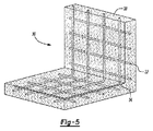
図4及び図5には、射出成形を用いて形成できる部材30が図示されている。部材30を形成するため、キャリヤ32をキャリヤ材料から矩形の形に切断する。次に、キャリヤ32を、射出成形機の金型内に配置し、金型を閉じる。キャリヤ32が図5に示すような曲がり部34を備えていない場合、これをもう一度切断し、曲がり部を金型内へのキャリヤ32の挿入に先立って予備成形するのが良く又は曲がり部34を金型の閉鎖時に形成するのが良い。しかる後、活性化可能材料38を比較的流体の状態に維持するが、材料38を実質的に活性化させることはない高い温度(例えば、代表的には、30℃以上、40℃以上、60℃以上、80℃以上、それどころか100℃以上であるが、代表的には220℃以下、170℃以下、120℃以下、100℃以下、それどころか70℃以下の温度)で金型内にキャリヤの周りに射出する。次に、活性化可能材料を放冷して活性化可能材料がキャリヤ32にくっつくようにし、それにより部材30を形成する。
4 and 5 show a
好ましい一実施形態によれば、活性化可能材料をキャリヤ又はキャリヤ材料の周りに押出し又は同時押出し成形する。かかる実施形態では、キャリヤ材料を好ましくは押出し機を出ている活性化可能材料と一緒に押出しダイに供給し、それにより複合押出し物を形成する。このようにすると、活性化可能材料は、キャリヤ材料を実質的に包囲することができる。しかる後、キャリヤ材料、活性化可能材料又はこれら両方を含む押出し物を所望の形状又は形態に合わせて切断して部材、例えば図5に示す部材30を形成することができる。好ましくは、必要条件ではないが、活性化可能材料38を比較的流体又は粘弾性の状態に維持するが、この材料38を実質的に活性化させることはない高い温度(例えば、代表的には、30℃以上、40℃以上、60℃以上、80℃以上、それどころか100℃以上であるが、代表的には220℃以下、170℃以下、120℃以下、100℃以下、それどころか70℃以下の温度)で活性化可能材料38を押し出す。すると、冷却時、活性化可能材料は、冷えてこれがキャリヤ32にくっつくようになり、それにより部材30を形成する。
According to one preferred embodiment, the activatable material is extruded or coextruded around the carrier or carrier material. In such an embodiment, the carrier material is fed to the extrusion die, preferably with the activatable material exiting the extruder, thereby forming a composite extrudate. In this way, the activatable material can substantially surround the carrier material. Thereafter, the extrudate containing the carrier material, the activatable material, or both can be cut to the desired shape or form to form a member, such as
有利には、これら技術を利用した部材の形成は、必要に応じ又は所望に応じて比較的複雑な又は単純な形状及び(又は)輪郭を部材に与えることができる。さらに、部材のキャリヤは、部材がこれらの形状を維持するのを助けると共に特に活性化可能材料がその形状を維持するのを助ける。 Advantageously, the formation of members utilizing these techniques can give the member a relatively complex or simple shape and / or contour as needed or desired. Furthermore, the carrier of the member helps the member maintain these shapes and in particular helps the activatable material maintain its shape.
本発明の上記実施形態のうちのどれにおいても、しかしながら、特にキャリヤが主として活性化可能材料を支持する役目を果たす状況において、活性化可能材料の体積は、キャリヤの体積よりも実質的に大きいことが好ましい。例えば、活性化可能材料の体積は、キャリヤの体積の少なくとも200%、一般的には少なくとも500%、より一般的には少なくとも800%であるのが良い。例示の計算を挙げると、10m3の体積の200%は、20m3である。 In any of the above embodiments of the invention, however, the volume of the activatable material is substantially greater than the volume of the carrier, particularly in situations where the carrier serves primarily to support the activatable material. Is preferred. For example, the volume of activatable material may be at least 200% of the volume of the carrier, typically at least 500%, more typically at least 800%. To give an example calculation, 200% of the volume of 10 m 3 is 20 m 3 .
さらに、本発明の部材は、これが製品(例えば自動車)の構造体に組み付けるのを助けるための1つ又は2つ以上のファスナ、例えば接着剤、機械的ファスナ、磁石等を有するのが良いことが想定される。かかるファスナは、キャリヤ、活性化可能材料又はこれら両方と同種の材料で一体形成(例えば、一体成形)されるのが良い。変形例として、1つ又は2つ以上のファスナを形成し、別々に部材に取り付けても良い。一例を挙げると、活性化可能材料の一部分を射出成形してこの部分が部材から外方に延びて製品の構造体の開口部内に締まり嵌め関係をなして入るようにするのが良い。変形例として、キャリヤの一部分が、部材から外方に延び、同様なやり方で取付け可能であっても良い。さらに別の変形例として、別個のファスナ、例えば両面テープ、磁石若しくはプッシュピン又は他の機械的ファスナを部材に取り付け、次にファスナを物品の構造体に取り付けても良い(例えば、くっつけ、磁気的に取り付け又は締まり嵌め関係をなして取り付けても良い)。 In addition, the members of the present invention may have one or more fasteners, such as adhesives, mechanical fasteners, magnets, etc., to assist in assembling it into the structure of a product (eg, an automobile). is assumed. Such fasteners may be integrally formed (eg, integrally formed) with the same type of material as the carrier, activatable material, or both. As a variation, one or more fasteners may be formed and separately attached to the member. In one example, a portion of the activatable material may be injection molded so that the portion extends outwardly from the member and enters the product structure opening in an interference fit relationship. Alternatively, a portion of the carrier may extend outward from the member and be attachable in a similar manner. As yet another variation, separate fasteners, such as double-sided tape, magnets or push pins, or other mechanical fasteners may be attached to the member, and then the fasteners attached to the article structure (eg, glued, magnetic Or may be attached in an interference fit relationship).
取付け
本発明の部材を種々の製品の種々の構造体上の種々の場所に取り付けることができる。一般に、本発明の部材は、内部キャビティを構成する材料への取付けに極めて適している。かかる状況では、部材をキャビティ内に配置するのが良く、そして部材の活性化可能材料を或る条件、例えば熱への暴露時(例えば、イーコート、プライマ又は塗料ベークオーブン内において)活性化させてこれが、膨張すると共に(或いは)バッフル、シール又は補強を構造体に提供するためのキャビティを画定する構造体の壁にくっつくようにするのが良い。
Mounting The members of the present invention can be mounted at various locations on various structures of various products. In general, the members of the present invention are very suitable for attachment to the material making up the internal cavity. In such situations, the member may be placed in the cavity and the activatable material of the member may be activated under certain conditions, such as exposure to heat (eg, in an ecoat, primer or paint bake oven). This may inflate and / or stick to the wall of the structure defining a cavity for providing baffles, seals or reinforcement to the structure.
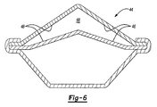
本発明の部材は、自動車の構造体への取付けに特に適していることが判明した。図6で理解できるように、自動車の構造体44(例えばピラー)が図示されており、この場合、構造体44は、内部キャビティ48を画定する壁46を有している。例示の目的のため、図5の部材30の形状は、その輪郭が図6の構造体44のキャビティ48の形状に一致するようなものである。かくして、部材30を、部材の外周部とキャビティ48を画定する壁46との間の隙間が比較的僅かな状態で(例えば、2.5cm未満、一般的には1.0cm未満、より一般的には0.4cm未満、更により一般的には0.2cm未満の状態で)キャビティ48内に配置できる。
The components of the present invention have been found to be particularly suitable for attachment to automobile structures. As can be seen in FIG. 6, an automobile structure 44 (e.g., a pillar) is shown, with the
キャビティ48内への部材30の配置後、活性化可能材料を活性化させてこれが膨張し(例えば発泡し)、硬化し(熱硬化し)、そして構造体44の壁46にくっつくようにする。部材30がバッフル、シール及び(又は)騒音軽減作用を構造体44に提供するよう設計されている場合、活性化可能材料は、代表的には、その非膨張状態の体積の少なくとも500%(場合によってはこれよりも低いが)、一般的には少なくとも800%、より一般的には少なくとも1400%の体積まで膨張し、この部材及び特に活性化材料(例えばフォーム)が、キャビティ48の断面を実質的に完全に跨ぐようにする。部材が補強用に設計されている場合、活性化可能材料は、代表的には、その元の非膨張状態の体積の少なくとも5%(場合によってはそうでなくても良いが)であるが、一般に600%未満、より一般的に400%未満、更により一般的には250%未満の体積まで膨張することになる。当然のことながら、部材は、バッフル、シール及び補強の組合せを構造体に提供して構造体が上述した作用の任意の組合せを備えるようにしても良い。さらに、部材は、上述の機能的属性の組合せをもたらすのを助けるよう2種類又は3種類以上の互いに異なる活性化可能材料を含んでも良い。
After placement of the
変形実施形態
図7及び図8は、本発明の別の実施形態としての部材50を示している。理解されるように、図7及び図8の部材50の特徴を上述の実施形態に加えて又はこれらに代えて用いることができ、又、先の実施形態の特徴を図7及び図8の部材50に用いても良い。図7及び図8の部材50は、展性キャリヤ52と、展性キャリヤ52の周りに配置されると共に実質的にこれを包囲した活性化可能な材料54と、オプションとして1つ又は2つ以上のファスナ58とを有する。
Modified Embodiments FIGS. 7 and 8 show a
展性可能キャリヤ52をキャリヤ52内に延び又はこれを貫通して延びる複数個(例えば2個、3個又は4個以上)の開口部62(例えば貫通穴)を備えた複数の幅広部分60を有する細長いストリップとして提供できる。キャリヤ52は、適当な展性キャリヤとして本明細書において説明した材料のうち任意のもので形成できる。
A plurality of
ファスナ58は、機械的ファスナ、特にプッシュピンとして図示されている。ファスナ58をキャリヤ52、活性化可能材料又はこれら両方に取り付けるのが良い(例えば、くっつけ、これらと締まり嵌め関係をなして取り付けるのが良い)。図示の実施形態では、ファスナ58の各々の細長い部分64をキャリヤの開口部62にそれぞれ挿通させることによりキャリヤ52に締まり嵌め関係をなしてファスナ58を取り付ける。
The fastener 58 is illustrated as a mechanical fastener, particularly a push pin. Fasteners 58 may be attached to
活性化可能材料54は、本明細書において説明した活性化可能材料のうちの任意のものであって良く、かかる活性化可能材料をキャリヤ52の周りに射出成形し、押出し成形し又は違ったやり方で成形すると共に(或いは)これに取り付けるのが良い。活性化可能材料を、図示の実施形態の場合のようにキャリヤ52及び1つ又は2つ以上のファスナ58の少なくとも一部分の周りに成形するのが好ましいが、これは必要条件ではない。
The
部材50を種々の技術により製品の構造体に取り付けることができる。一例を挙げると、部材50のファスナ58を自動車の構造体(例えばピラー、例えば図6に示すピラー)の開口部(例えば貫通穴)内に締まり嵌め関係をなして入れて活性化可能材料が構造体のキャビティ内に配置されるようにするのが良い。変形例として、ファスナ58は、補助キャリヤの開口部内に締まり嵌め関係をなして入れ、補助キャリヤを部材50と一緒に構造体のキャビティ内に配置しても良い。
The
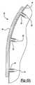
有利には、展性キャリヤ52により、部材を取り付け中に成形して(例えば曲げて又は湾曲させて)これが構造体又は補助キャリヤの輪郭に適合するようにすることができ、それにより、部材を一層容易にこれに取り付けることができる。図8Aに示すように、部材50は、輪郭付けられた(異形の)又は湾曲した機材66(例えば構造体又は補助キャリヤ)に取り付けられ、部材50は、基材66の湾曲又は輪郭付け表面に適合するよう湾曲され又は輪郭付けられている。好ましくは、キャビティ内への配置後、活性化可能材料を上述したように活性化させて補強、バッフル又はシールを構造体に提供するのが良い。
Advantageously,
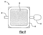
図9及び図10は、本発明の別の実施形態としての部材80を示している。理解されるように、図9及び図10の部材80の特徴を上述の実施形態に加えて又はこれらに代えて用いることができ、又、先の実施形態の特徴を図9及び図10の部材80に用いても良い。図9及び図10の部材80は、展性キャリヤ82と、展性キャリヤ82上又はその周りに配置された活性化可能な材料84と、オプションとして1つ又は2つ以上のファスナ8890とを有する。
9 and 10 show a
展性キャリヤ82を細長いストリップで作られたフレーム(矩形の状態で示されている)として提供できる。キャリヤ82は、適当な展性キャリヤとして本明細書において説明した材料のうち任意のもので形成することができる。
The
ファスナ88,90は、機械的ファスナ、特にタブとして図示されており、タブは、好ましくは、曲げ可能であり、キャリヤ82と同種の材料で一体形成されている。図示のように、第1のファスナ88は、キャリヤ82の一方の側から延び、第2のファスナ90は、キャリヤ82の反対側から延びている。第1のファスナ88は、全体としてフックの形をしている。
The
活性化可能材料84は、本明細書において説明した活性化可能材料のうちの任意のものであって良く、手動、自動的又は違ったやり方でキャリヤ82に取付け可能である。活性化可能材料84が粘着性である場合、材料の1つ又は2つ以上の表面を剥離紙で被覆することが望ましい場合があり、この剥離紙は、構造体への部材80の取付け直前に材料から除去されるのが良い。図示の実施形態では、活性化可能材料84は、全体としてキャリヤ82の形状に一致した形状(例えば矩形)を有し、材料84は、キャリヤ82の少なくとも1つの表面94にくっつけられる。
The
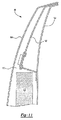
部材80を種々の技術に従って製品の構造体に取り付けることができる。図11では、部材は、車両のピラー構造体98に取り付けられる。図示のように、ピラー構造体98は、車体の側部内側部材として示された第1の部材100と、車体の側部補強材として示された第2の部材102と、車体の側部外側部材として示された第3の部材104とを有している。第1のファスナ88を部材102に設けられている開口部に通し、第1のファスナ84を第2の部材102の縁部上に引っ掛けることにより部材80を構造体98の第2の部材102に取り付ける。しかる後、少なくとも一時的に部材80を構造体98、特に第2の部材102に締結するために第2のファスナ90を第2の部材102の遠位端部のところの縁部周りに曲げることにより第2のファスナ90を第2の部材102の遠位端部のところの縁部の周りに曲げてこれに引っ掛ける。
The
好ましくは、キャビティ内への配置後、活性化可能材料を上述したように活性化させて補強、バッフル又はシール構造体に提供するのが良い。図示の特定の実施形態では、部材80を第1の部材100と第3の部材100との間に画定されたキャビティ110内で活性化させ、そして活性化可能材料を活性化させて補強(例えば座屈に対する補強)を構造体98に提供するだけでなく、2つの補強材、例えば第2の部材102と構造体98のための下側補強材112との間の連結状態を比較的強固に補強するのが良い。
Preferably, after placement in the cavity, the activatable material is activated as described above to provide a reinforcement, baffle or seal structure. In the particular embodiment shown,
別段の言及がなければ、本明細書において説明した種々の構造体の寸法及び幾何学的形状は、本発明を限定するものではなく、他の寸法又は幾何学的形状の採用が可能である。複数の構造的コンポーネントは、単一の一体形構造体によって提供できる。変形例として、単一の一体形構造体を別々の複数のコンポーネントの状態に分割しても良い。加うるに、本発明の特徴は、図示の実施形態のうちの1つだけと関連して説明されているが、かかる特徴は、任意所与の用途に関し、他の実施形態の1つ又は2つ以上の他の特徴と組み合わせることができる。また、上述のことから、本明細書における新規な構造体の製作及びその作用も又、本発明の方法を構成することは理解されよう。 Unless otherwise noted, the dimensions and geometric shapes of the various structures described herein are not intended to limit the present invention and other dimensions or geometric shapes can be employed. Multiple structural components can be provided by a single unitary structure. As a modification, a single integrated structure may be divided into separate components. In addition, while features of the present invention have been described in connection with only one of the illustrated embodiments, such features can be used with any one or two of the other embodiments for any given application. Can be combined with one or more other features. It will also be appreciated from the above that the fabrication and operation of the novel structure herein also constitutes the method of the present invention.
本発明の好ましい実施形態を開示した。しかしながら、当業者であれば、或る特定の改造例が本発明の教示の範囲内で相当できることは認識されよう。したがって、特許請求の範囲の記載は、本発明の真の範囲及び内容を定めるものとして検討されるべきである。 A preferred embodiment of the present invention has been disclosed. However, those skilled in the art will recognize that certain modifications can be made within the scope of the teachings of the present invention. Accordingly, the claims should be considered as defining the true scope and content of the invention.
Claims (16)
複数のファスナを前記複数の貫通孔に通すステップと、
活性化可能な材料を前記展性キャリヤに関連させ、それにより前記部材を形成するステップであって、膨張の前において、前記活性化可能な材料の体積は、前記展性キャリヤの体積の少なくとも500%であり、これにより、前記部材を形成するため前記活性化可能な材料は前記キャリヤを実質的に全体的に包囲するステップと、
前記展性キャリヤ、前記活性化可能材料、またはこれら両方を成形するステップとを備え、
前記成形ステップ及び関連させるステップは、次のステップ、即ち
i.前記展性キャリヤを車両のキャビティに対応する所定の形態に合わせて成形し、前記活性化可能材料を前記展性キャリヤ上にモールディングするステップと、
ii.前記活性化可能材料を前記展性キャリヤ上にモールディングして前記部材を形成し、前記部材を、車両のキャビティ内への部材の配置前又は配置中に前記展性キャリヤ及び前記活性化可能材料の成形を含むやり方で構造体に取り付けるステップの少なくとも1つのステップを含み、
前記活性化可能な材料を膨張させ、前記車両の一部分を補強することを助ける構造的な発泡体を形成するステップを備え、
前記活性化可能な材料を前記展性キャリヤに関連させるステップは、前記展性キャリヤを前記活性化可能な材料で実質的に包囲するステップを含む、
ことを特徴とする方法。 A method for forming and / or attaching a member that reinforces an automobile structure, which is malleable in the form of a single elongated strip formed of a plastic or metal material having a yield stress greater than 100 Mpa and less than 1000 Mpa Providing a carrier, wherein the malleable carrier comprises a plurality of wide portions, each of the wide portions having one of a plurality of through holes passing therethrough;
Passing a plurality of fasteners through the plurality of through holes;
Associating an activatable material with the malleable carrier, thereby forming the member, wherein prior to expansion, the volume of activatable material is at least 500 of the volume of the malleable carrier. % So that the activatable material substantially entirely surrounds the carrier to form the member;
Molding the malleable carrier, the activatable material, or both,
The shaping step and the associating step comprise the following steps: i. Molding the malleable carrier into a predetermined shape corresponding to a vehicle cavity, and molding the activatable material onto the malleable carrier;
ii. Molding the activatable material onto the malleable carrier to form the member, wherein the member is disposed of the malleable carrier and the activatable material prior to or during placement of the member within a vehicle cavity. Including at least one step of attaching to the structure in a manner that includes molding;
Inflating the activatable material to form a structural foam that helps to reinforce a portion of the vehicle;
Associating the activatable material with the malleable carrier comprises substantially enclosing the malleable carrier with the activatable material;
A method characterized by that.
請求項1記載の方法。 The malleable carrier has a yield stress of less than about 700 MPa and greater than about 100 MPa;
The method of claim 1.
請求項1又は2記載の方法。 The activatable material is generally dry and substantially non-tacky;
The method according to claim 1 or 2.
請求項1、2又は3記載の方法。 The malleable carrier is made of metal,
4. A method according to claim 1, 2 or 3.
請求項1、2、3又は4記載の方法。 The malleable carrier is made of one or more strips;
5. A method according to claim 1, 2, 3 or 4.
請求項1、2、3、4又は5記載の方法。 The malleable carrier has a yield stress of less than about 500 Mpa and greater than about 250 Mpa;
6. A method according to claim 1, 2, 3, 4 or 5.
請求項1ないし4のいずれか1項に記載の方法。 The malleable carrier is formed of a plurality of strips twisted together,
5. A method according to any one of claims 1 to 4 .
請求項1ないし7のいずれか1項に記載の方法。 The malleable carrier is formed of a wire mesh,
8. A method according to any one of claims 1 to 7.
ii.前記展性キャリヤを成形する前記ステップは、前記第1のタブを構造体の第1の縁部周りに引っ掛け、前記第2のタブを前記構造体の第2の縁部周りに曲げるステップを含む、
請求項1ないし5のいずれか1項に記載の方法。 i. The malleable carrier has a frame portion, a first tab, and a second tab, the first tab being in the form of a hook;
ii. The step of molding the malleable carrier includes hooking the first tab around a first edge of the structure and bending the second tab around the second edge of the structure. ,
6. A method according to any one of claims 1-5.
該部材取付けステップは、前記展性キャリヤ及び前記活性化可能材料を含む前記部材を成形して前記補助キャリヤの1つ又は2つ以上の輪郭に合わせるステップを含む、
請求項1ないし6のうちいずれか1項に記載の方法。 The step of forming includes attaching the member to an auxiliary carrier;
The member mounting step includes forming the member including the malleable carrier and the activatable material to conform to one or more contours of the auxiliary carrier.
The method according to any one of claims 1 to 6.
請求項10記載の方法。 The forming step includes a step of bending or bending the member.
The method of claim 10.
請求項10又は11記載の方法。 The malleable carrier is in the form of a single elongate strip with a plurality of through holes,
12. A method according to claim 10 or 11.
請求項10、11又は12記載の方法。 The malleable carrier has a plurality of wide portions, and each of the plurality of through holes is provided through each of the wide portions.
13. A method according to claim 10, 11 or 12.
請求項12又は13記載の方法。 Passing a plurality of fasteners through the plurality of through-holes, wherein the attaching step of the member comprises attaching the fastener to the structure or the auxiliary carrier;
14. A method according to claim 12 or 13.
請求項14記載の方法。 The activatable material is molded around at least a portion of the plurality of fasteners;
The method of claim 14.
請求項1ないし15のいずれか1項に記載の方法。 The activatable material is a thermally activated thermosetting material that expands, expands, and cures when exposed to temperatures in an e-coat oven or bake oven.
16. A method according to any one of claims 1 to 15.
Applications Claiming Priority (5)
| Application Number | Priority Date | Filing Date | Title |
|---|---|---|---|
| US70556105P | 2005-08-04 | 2005-08-04 | |
| US60/705,561 | 2005-08-04 | ||
| US11/461,557 | 2006-08-01 | ||
| US11/461,557 US7926179B2 (en) | 2005-08-04 | 2006-08-01 | Reinforcements, baffles and seals with malleable carriers |
| PCT/US2006/030480 WO2007019330A1 (en) | 2005-08-04 | 2006-08-02 | Reinforcements, baffles and seals with malleable carriers |
Publications (3)
| Publication Number | Publication Date |
|---|---|
| JP2009502592A JP2009502592A (en) | 2009-01-29 |
| JP2009502592A5 JP2009502592A5 (en) | 2009-09-17 |
| JP5236471B2 true JP5236471B2 (en) | 2013-07-17 |
Family
ID=37453105
Family Applications (1)
| Application Number | Title | Priority Date | Filing Date |
|---|---|---|---|
| JP2008525233A Expired - Fee Related JP5236471B2 (en) | 2005-08-04 | 2006-08-02 | Stiffeners, baffles and seals with malleable carriers |
Country Status (7)
| Country | Link |
|---|---|
| US (3) | US7926179B2 (en) |
| EP (1) | EP1910052A1 (en) |
| JP (1) | JP5236471B2 (en) |
| KR (1) | KR101359240B1 (en) |
| CN (1) | CN101356051B (en) |
| CA (1) | CA2617919C (en) |
| WO (1) | WO2007019330A1 (en) |
Families Citing this family (38)
| Publication number | Priority date | Publication date | Assignee | Title |
|---|---|---|---|---|
| US7926179B2 (en) | 2005-08-04 | 2011-04-19 | Zephyros, Inc. | Reinforcements, baffles and seals with malleable carriers |
| US8002332B2 (en) | 2007-01-30 | 2011-08-23 | Zephyros, Inc. | Structural mounting insert |
| DE102007024311A1 (en) * | 2007-05-24 | 2008-11-27 | GM Global Technology Operations, Inc., Detroit | foam element |
| US7641264B2 (en) * | 2007-10-05 | 2010-01-05 | Sika Technology, AG | Reinforcement device |
| US20090096251A1 (en) * | 2007-10-16 | 2009-04-16 | Sika Technology Ag | Securing mechanism |
| US8020924B2 (en) * | 2007-12-26 | 2011-09-20 | Sika Technology Ag | Integrated reinforcing crossmember |
| US9194408B2 (en) | 2008-02-08 | 2015-11-24 | Zephyros, Inc. | Mechanical method for improving bond joint strength |
| US8181327B2 (en) | 2008-02-08 | 2012-05-22 | Zephyros, Inc | Mechanical method for improving bond joint strength |
| US8293360B2 (en) * | 2008-02-27 | 2012-10-23 | Sika Technology Ag | Baffle |
| US7913814B2 (en) * | 2008-03-07 | 2011-03-29 | Henkel Corporation | Acoustic baffle assembly |
| US8388037B2 (en) * | 2008-04-04 | 2013-03-05 | Sika Technology Ag | Expandable barrier |
| GB0806434D0 (en) * | 2008-04-09 | 2008-05-14 | Zephyros Inc | Improvements in or relating to structural adhesives |
| US8133929B2 (en) * | 2008-04-15 | 2012-03-13 | Sika Technology Ag | Method for incorporating long glass fibers into epoxy-based reinforcing resins |
| ATE535432T1 (en) * | 2008-08-05 | 2011-12-15 | Sika Technology Ag | SOUND-ABSORBING BULKHEAD PART |
| JP2012509806A (en) | 2008-11-26 | 2012-04-26 | ダウ グローバル テクノロジーズ エルエルシー | Sound absorbing baffle member and method for applying sound absorbing baffle in cavity |
| EP2237195B1 (en) | 2009-04-03 | 2012-07-25 | 3M Innovative Properties Company | A material for packaging electronic components |
| US7984919B2 (en) * | 2009-05-18 | 2011-07-26 | Zephyros, Inc. | Structural mounting insert having a non-conductive isolator |
| CA2787703A1 (en) | 2010-01-20 | 2011-07-28 | The Flewelling Ford Family Trust | Mesh lighting system for emergency vehicles |
| KR20130020772A (en) * | 2010-03-04 | 2013-02-28 | 제피로스, 인크. | Structural composite laminate |
| US8545956B2 (en) | 2010-04-26 | 2013-10-01 | Sika Technology Ag | Expandable insert with flexible substrate |
| WO2012125995A1 (en) | 2011-03-17 | 2012-09-20 | Zephyros, Inc. | Bonding assembly |
| CN102490368A (en) * | 2011-12-16 | 2012-06-13 | 北京科技大学 | Method for manufacturing metal/resin/metal sound insulation material |
| DE102012018410A1 (en) * | 2012-09-17 | 2014-03-20 | GM Global Technology Operations LLC (n. d. Ges. d. Staates Delaware) | SEALING DEVICE |
| US9381716B2 (en) * | 2012-09-26 | 2016-07-05 | Zephyros, Inc. | Structural adhesive assemblies |
| US20140250846A1 (en) * | 2013-02-26 | 2014-09-11 | Research Triangle Institute | Curved nanofiber products and applications thereof |
| WO2014095620A1 (en) * | 2012-12-21 | 2014-06-26 | Sika Technology Ag | Insulation element, expanded insulation element, use of same and method for insulation |
| DE202014011009U1 (en) | 2013-07-26 | 2017-06-02 | Zephyros Inc. | Thermosetting adhesive films with a fiber carrier |
| GB201318595D0 (en) | 2013-10-21 | 2013-12-04 | Zephyros Inc | Improvements in or relating to laminates |
| US10421260B2 (en) | 2013-12-17 | 2019-09-24 | Zephyros, Inc. | Carrier with localized fibrous insert and methods |
| GB201417985D0 (en) | 2014-10-10 | 2014-11-26 | Zephyros Inc | Improvements in or relating to structural adhesives |
| WO2016176459A1 (en) * | 2015-04-30 | 2016-11-03 | Zephyros, Inc. | Members for sealing, baffling, or reinforcing |
| US10780672B2 (en) | 2015-05-14 | 2020-09-22 | Zephyros, Inc. | Localized panel stiffener |
| CN113910724B (en) * | 2016-03-02 | 2024-06-11 | 泽菲罗斯有限公司 | Discontinuous net structure |
| BR112018068654B1 (en) * | 2016-03-16 | 2023-02-14 | Zephyros, Inc. | ARTICLE AND METHOD FOR FORMING THE ARTICLE |
| WO2019055710A1 (en) * | 2017-09-13 | 2019-03-21 | Zephyros, Inc. | Composite structures for localized stiffening |
| US11332199B2 (en) * | 2017-11-14 | 2022-05-17 | Sika Technology Ag | Device for reinforcing, sealing or damping a structural element |
| USD938887S1 (en) | 2018-06-21 | 2021-12-21 | Zephyros, Inc. | Sealing device |
| CN113939402A (en) * | 2019-07-26 | 2022-01-14 | Sika技术股份公司 | Expansion element |
Family Cites Families (214)
| Publication number | Priority date | Publication date | Assignee | Title |
|---|---|---|---|---|
| US3400182A (en) | 1965-08-03 | 1968-09-03 | Budd Co | Method of interconnecting spaced panels and means for use therein |
| AT292275B (en) | 1967-07-06 | 1971-08-25 | Graeff Roderich Wilhelm | Large-area plate-shaped component made of thermosetting plastics |
| US3649375A (en) | 1970-01-26 | 1972-03-14 | Western Electric Co | Method of forming metallic material |
| US3868796A (en) | 1973-04-04 | 1975-03-04 | Ford Motor Co | Side door intrusion protection |
| JPS54160464A (en) * | 1978-06-08 | 1979-12-19 | Nhk Spring Co Ltd | Plastic sheet frame |
| US4352484A (en) | 1980-09-05 | 1982-10-05 | Energy Absorption Systems, Inc. | Shear action and compression energy absorber |
| US4610836A (en) | 1983-09-12 | 1986-09-09 | General Motors Corporation | Method of reinforcing a structural member |
| US4463870A (en) | 1983-10-19 | 1984-08-07 | L & L Products, Inc. | Closure plate for an opening |
| US4707397A (en) | 1984-05-21 | 1987-11-17 | Bridgestone Corporation | Vibration damping metal panels |
| US4769391A (en) | 1985-12-19 | 1988-09-06 | Essex Composite Systems | Reinforcement insert for a structural member and method of making and using the same |
| US4751249A (en) | 1985-12-19 | 1988-06-14 | Mpa Diversified Products Inc. | Reinforcement insert for a structural member and method of making and using the same |
| EP0236291B1 (en) | 1986-02-21 | 1991-04-17 | Austria Metall Aktiengesellschaft | Guard bar, especially for reinforcing of motor vehicle doors |
| DE3637751A1 (en) | 1986-11-05 | 1988-05-11 | Bayer Ag | PLASTIC SHOCK ABSORBER WITH BUMPER |
| US4901500A (en) | 1987-09-18 | 1990-02-20 | Essex Composite Systems | Lightweight composite beam |
| US4861097A (en) | 1987-09-18 | 1989-08-29 | Essex Composite Systems | Lightweight composite automotive door beam and method of manufacturing same |
| US4813690A (en) | 1987-11-24 | 1989-03-21 | L & L Products, Inc. | Sealing member |
| US4923902A (en) | 1988-03-10 | 1990-05-08 | Essex Composite Systems | Process and compositions for reinforcing structural members |
| US4836516A (en) | 1988-04-25 | 1989-06-06 | Essex Composite Systems | Filled tubular torsion bar and its method of manufacture |
| US4853270A (en) | 1988-06-27 | 1989-08-01 | Essex Specialty Products, Inc. | Knee blocker for automotive application |
| US4810548A (en) * | 1988-08-01 | 1989-03-07 | Ligon Brothers Manufacturing Company | Sandwich seal fixture |
| US5124186A (en) | 1990-02-05 | 1992-06-23 | Mpa Diversified Products Co. | Composite tubular door beam reinforced with a reacted core localized at the mid-span of the tube |
| US4978562A (en) | 1990-02-05 | 1990-12-18 | Mpa Diversified Products, Inc. | Composite tubular door beam reinforced with a syntactic foam core localized at the mid-span of the tube |
| US5213391A (en) | 1990-10-25 | 1993-05-25 | Nissan Motor Co., Ltd. | Body skeleton element of vehicle and manufacturing method thereof |
| US5344208A (en) * | 1991-12-09 | 1994-09-06 | Chrysler Corporation | Reinforcement assembly for vehicle panels |
| DE4226988A1 (en) | 1992-08-14 | 1994-02-17 | Wulfram John Schmucker | Composite shaped pieces with sandwich structure - have centre layer of foamed synthetic resin and outer layers of natural fibres oriented in specified directions. |
| US5288538A (en) | 1992-12-16 | 1994-02-22 | Reynolds Metals Company | Expandable honeycomb core structural member |
| US5266133A (en) | 1993-02-17 | 1993-11-30 | Sika Corporation | Dry expansible sealant and baffle composition and product |
| US5358397A (en) | 1993-05-10 | 1994-10-25 | L&L Products, Inc. | Apparatus for extruding flowable materials |
| EP0703931B1 (en) | 1993-06-16 | 2003-10-01 | Minnesota Mining And Manufacturing Company | Vibration damping constructions using thermally polymerized epoxides |
| US5932680A (en) | 1993-11-16 | 1999-08-03 | Henkel Kommanditgesellschaft Auf Aktien | Moisture-curing polyurethane hot-melt adhesive |
| JPH0731569U (en) * | 1993-12-02 | 1995-06-13 | 株式会社ネオックスラボ | Attachment structure of foamable material in hollow structure and processed body for attachment of foamable material |
| EP0679501A1 (en) | 1994-03-14 | 1995-11-02 | YMOS AKTIENGESELLSCHAFT Industrieprodukte | Composite material with foamable core |
| DE29522122U1 (en) | 1994-03-14 | 1999-11-18 | Magna Exterior Systems GmbH, 63179 Obertshausen | Composite |
| US6168226B1 (en) | 1994-05-19 | 2001-01-02 | Henkel Corporation | Composite laminate automotive structures |
| US5575526A (en) | 1994-05-19 | 1996-11-19 | Novamax Technologies, Inc. | Composite laminate beam for radiator support |
| US5506025A (en) | 1995-01-09 | 1996-04-09 | Sika Corporation | Expandable baffle apparatus |
| JP2721327B2 (en) * | 1995-02-09 | 1998-03-04 | 株式会社ネオックスラボ | Support structure of foamable material in hollow structure |
| US5642914A (en) * | 1995-03-24 | 1997-07-01 | Neo-Ex Lab. Inc. | Support structure for supporting foamable material on hollow structural member |
| US6165588A (en) | 1998-09-02 | 2000-12-26 | Henkel Corporation | Reinforcement of hollow sections using extrusions and a polymer binding layer |
| US5755486A (en) | 1995-05-23 | 1998-05-26 | Novamax Technologies Holdings, Inc. | Composite structural reinforcement member |
| JP3501879B2 (en) | 1995-07-31 | 2004-03-02 | 株式会社ネオックスラボ | Support structure of foamable material in hollow structure |
| DE19528825A1 (en) | 1995-08-05 | 1997-02-06 | Sika Ag | Soundproofing partition |
| US5985435A (en) | 1996-01-23 | 1999-11-16 | L & L Products, Inc. | Magnetized hot melt adhesive articles |
| JP3648743B2 (en) | 1996-02-02 | 2005-05-18 | 東レ株式会社 | "Resin composition for fiber reinforced composite material and its manufacturing method, prepreg, fiber reinforced composite material, honeycomb structure" |
| US6341467B1 (en) | 1996-05-10 | 2002-01-29 | Henkel Corporation | Internal reinforcement for hollow structural elements |
| FR2749263B1 (en) | 1996-05-31 | 1998-07-03 | Renault | REINFORCED STRUCTURAL ELEMENT AND MANUFACTURING METHOD THEREOF |
| US5725272A (en) | 1996-06-27 | 1998-03-10 | Sika Corporation | Drain assembly for acoustic baffle system |
| US5888600A (en) | 1996-07-03 | 1999-03-30 | Henkel Corporation | Reinforced channel-shaped structural member |
| US6270600B1 (en) | 1996-07-03 | 2001-08-07 | Henkel Corporation | Reinforced channel-shaped structural member methods |
| US6482496B1 (en) | 1996-07-03 | 2002-11-19 | Henkel Corporation | Foil backed laminate reinforcement |
| DE19632550A1 (en) | 1996-08-13 | 1998-02-19 | Moeller Plast Gmbh | Wall or building element and process for its manufacture |
| JP3516816B2 (en) * | 1996-08-30 | 2004-04-05 | 株式会社ネオックスラボ | Hollow chamber blocker for hollow structure and method of manufacturing the same |
| DE19707136C2 (en) | 1997-02-22 | 2001-03-08 | Moeller Plast Gmbh | Process and foamable mass for the foaming or foam coating of components |
| US5904024A (en) * | 1997-02-26 | 1999-05-18 | Axxis Corp. | Mount construction of foam substrate in hollow structures |
| US6099948A (en) * | 1997-05-08 | 2000-08-08 | Henkel Corporation | Encapsulation of pre-expanded elastomeric foam with a thermoplastic |
| DE19721608C2 (en) | 1997-05-23 | 2002-03-07 | Daimler Chrysler Ag | Energy absorbing element |
| US6237304B1 (en) | 1997-07-18 | 2001-05-29 | Henkel Corporation | Laminate structural bulkhead |
| US6096403A (en) | 1997-07-21 | 2000-08-01 | Henkel Corporation | Reinforced structural members |
| US6233826B1 (en) * | 1997-07-21 | 2001-05-22 | Henkel Corp | Method for reinforcing structural members |
| DE19736839A1 (en) | 1997-08-23 | 1999-02-25 | Volkswagen Ag | Deformation structure for occupant protection in vehicles |
| JP4202596B2 (en) | 1997-08-26 | 2008-12-24 | シーカ・シュヴァイツ・アーゲー | Support structure reinforcement device |
| AU9492698A (en) | 1997-09-26 | 1999-04-23 | Dow Chemical Company, The | Flexible epoxy sound damping coatings |
| DE19753318A1 (en) | 1997-12-02 | 1999-06-10 | Sika Ag | Reinforcing element for load-bearing or load-transmitting components and method for fastening it to a component surface |
| US6103341A (en) | 1997-12-08 | 2000-08-15 | L&L Products | Self-sealing partition |
| US6093358A (en) * | 1998-01-27 | 2000-07-25 | Lear Corporation | Method of making an expandable gap filling product |
| US6068424A (en) | 1998-02-04 | 2000-05-30 | Henkel Corporation | Three dimensional composite joint reinforcement for an automotive vehicle |
| US6003274A (en) | 1998-02-13 | 1999-12-21 | Henkel Corporation | Lightweight laminate reinforcing web |
| DE19856255C1 (en) | 1998-03-20 | 2000-01-20 | Moeller Plast Gmbh | Hollow profile with internal reinforcement |
| DE19812288C1 (en) | 1998-03-20 | 1999-05-27 | Moeller Plast Gmbh | Hollow profile for motor vehicle bodywork |
| US6372334B1 (en) | 1998-03-30 | 2002-04-16 | Henkel Corporation | Reinforcement laminate |
| US6079180A (en) | 1998-05-22 | 2000-06-27 | Henkel Corporation | Laminate bulkhead with flared edges |
| US5992923A (en) | 1998-05-27 | 1999-11-30 | Henkel Corporation | Reinforced beam assembly |
| US6146565A (en) * | 1998-07-15 | 2000-11-14 | Noble Polymers, L.L.C. | Method of forming a heat expandable acoustic baffle |
| US6103152A (en) | 1998-07-31 | 2000-08-15 | 3M Innovative Properties Co. | Articles that include a polymer foam and method for preparing same |
| US6247287B1 (en) * | 1998-08-05 | 2001-06-19 | Neo-Ex Lab, Inc. | Structure and method for closing and reinforcing hollow structural members |
| US6272809B1 (en) | 1998-09-09 | 2001-08-14 | Henkel Corporation | Three dimensional laminate beam structure |
| US6033300A (en) | 1998-10-21 | 2000-03-07 | L & L Products, Inc. | Automotive vehicle HVAC rainhat |
| US6387470B1 (en) | 1998-11-05 | 2002-05-14 | Sika Corporation | Sound deadening and structural reinforcement compositions and methods of using the same |
| DE19858903B4 (en) | 1998-12-19 | 2015-07-23 | GM Global Technology Operations LLC (n. d. Ges. d. Staates Delaware) | Reinforcing element for a hollow body, in particular for a vehicle body spar, method for introducing such a reinforcing element into a hollow body and vehicle body with such a reinforced body spar |
| DE29904705U1 (en) | 1998-12-23 | 1999-06-17 | Mannesmann AG, 40213 Düsseldorf | Device for producing a profile part |
| US6276105B1 (en) | 1999-01-11 | 2001-08-21 | Henkel Corporation | Laminate reinforced beam with tapered polymer layer |
| US6149227A (en) | 1999-01-25 | 2000-11-21 | Henkel Corporation | Reinforced structural assembly |
| US6189953B1 (en) | 1999-01-25 | 2001-02-20 | Henkel Corporation | Reinforced structural assembly |
| US6092864A (en) | 1999-01-25 | 2000-07-25 | Henkel Corporation | Oven cured structural foam with designed-in sag positioning |
| DE19908347C1 (en) | 1999-02-26 | 2001-01-04 | Moeller Plast Gmbh | Holder plate with means for fixing the functional position |
| DE19909270A1 (en) | 1999-03-03 | 2000-09-07 | Henkel Teroson Gmbh | Thermosetting, thermally expandable molded body |
| US6131897A (en) | 1999-03-16 | 2000-10-17 | L & L Products, Inc. | Structural reinforcements |
| US6261675B1 (en) | 1999-03-23 | 2001-07-17 | Hexcel Corporation | Core-crush resistant fabric and prepreg for fiber reinforced composite sandwich structures |
| KR20010011778A (en) | 1999-07-30 | 2001-02-15 | 정몽규 | Expandable reinforcement pad for automative panel |
| US6150428A (en) | 1999-09-28 | 2000-11-21 | Sika Corporation | Expansion temperature tolerant dry expandable sealant and baffle product and method of preparing same |
| US6358584B1 (en) * | 1999-10-27 | 2002-03-19 | L&L Products | Tube reinforcement with deflecting wings and structural foam |
| USH2047H1 (en) | 1999-11-10 | 2002-09-03 | Henkel Corporation | Reinforcement laminate |
| JP4476438B2 (en) | 1999-11-12 | 2010-06-09 | 株式会社ネオックスラボ | Hollow structure reinforcement |
| US6263635B1 (en) | 1999-12-10 | 2001-07-24 | L&L Products, Inc. | Tube reinforcement having displaceable modular components |
| US6668457B1 (en) | 1999-12-10 | 2003-12-30 | L&L Products, Inc. | Heat-activated structural foam reinforced hydroform |
| JP3428545B2 (en) | 2000-01-07 | 2003-07-22 | 本田技研工業株式会社 | Body reinforcement structure |
| US6253524B1 (en) * | 2000-01-31 | 2001-07-03 | Sika Corporation | Reinforcing member with thermally expansible structural reinforcing material and directional shelf |
| US6199940B1 (en) | 2000-01-31 | 2001-03-13 | Sika Corporation | Tubular structural reinforcing member with thermally expansible foaming material |
| AU2001231087A1 (en) | 2000-01-31 | 2001-08-07 | Sika Corporation | Structural reinforcing member with ribbed thermally expansible foaming material |
| US6305136B1 (en) | 2000-01-31 | 2001-10-23 | Sika Corporation | Reinforcing member with beam shaped carrier and thermally expansible reinforcing material |
| US6475577B1 (en) * | 2000-02-07 | 2002-11-05 | Sika Corporation | Reinforcing member with intersecting support legs |
| US6467834B1 (en) | 2000-02-11 | 2002-10-22 | L&L Products | Structural reinforcement system for automotive vehicles |
| WO2001058741A1 (en) | 2000-02-11 | 2001-08-16 | L & L Products, Inc. | Structural reinforcement system for automotive vehicles |
| US6296298B1 (en) | 2000-03-14 | 2001-10-02 | L&L Products, Inc. | Structural reinforcement member for wheel well |
| US6422575B1 (en) | 2000-03-14 | 2002-07-23 | L&L Products, Inc. | Expandable pre-formed plug |
| US6482486B1 (en) | 2000-03-14 | 2002-11-19 | L&L Products | Heat activated reinforcing sleeve |
| FR2806425B1 (en) | 2000-03-16 | 2002-07-12 | Hexcel Composites | COMPOSITE INTERMEDIATE PRODUCT, PROCESS FOR PRODUCING SUCH A PRODUCT, AND USE AS A MOLDING MATERIAL |
| US6382635B1 (en) | 2000-03-17 | 2002-05-07 | Sika Corporation | Double walled baffle |
| US6413611B1 (en) * | 2000-05-01 | 2002-07-02 | Sika Corporation | Baffle and reinforcement assembly |
| US6196621B1 (en) * | 2000-05-24 | 2001-03-06 | Daimlerchrysler Corporation | Apparatus for transferring impact energy from a tire and wheel assembly of a motor vehicle to a sill |
| AU2001275059A1 (en) | 2000-06-06 | 2001-12-17 | Dow Global Technologies Inc | Epoxy based reinforcing patches with improved adhesion to oily metal surfaces |
| US6321793B1 (en) | 2000-06-12 | 2001-11-27 | L&L Products | Bladder system for reinforcing a portion of a longitudinal structure |
| US6319964B1 (en) | 2000-06-30 | 2001-11-20 | Sika Corporation | Acoustic baffle with predetermined directional expansion characteristics |
| US6523857B1 (en) | 2000-07-05 | 2003-02-25 | Sika Corporation | Reinforcing member for interfitting channels |
| US6820923B1 (en) | 2000-08-03 | 2004-11-23 | L&L Products | Sound absorption system for automotive vehicles |
| US6634698B2 (en) | 2000-08-14 | 2003-10-21 | L&L Products, Inc. | Vibrational reduction system for automotive vehicles |
| JP2002067826A (en) | 2000-08-25 | 2002-03-08 | Nissan Motor Co Ltd | Vehicular noise absorbing and insulating structure |
| US6494525B1 (en) * | 2000-09-15 | 2002-12-17 | Sika Corporation | Side impact reinforcement |
| US6419305B1 (en) | 2000-09-29 | 2002-07-16 | L&L Products, Inc. | Automotive pillar reinforcement system |
| US6561571B1 (en) | 2000-09-29 | 2003-05-13 | L&L Products, Inc. | Structurally enhanced attachment of a reinforcing member |
| US6471285B1 (en) | 2000-09-29 | 2002-10-29 | L&L Products, Inc. | Hydroform structural reinforcement system |
| KR100327154B1 (en) * | 2000-10-13 | 2002-03-13 | 박호군 | High Concentrated Organic Wastewater Treatment Process Using Bio-maker |
| JP2002120250A (en) | 2000-10-16 | 2002-04-23 | Neoex Lab Inc | Filling implement of hollow structure and method for filling |
| US6455146B1 (en) | 2000-10-31 | 2002-09-24 | Sika Corporation | Expansible synthetic resin baffle with magnetic attachment |
| US20040079478A1 (en) | 2000-11-06 | 2004-04-29 | Sika Ag, Vorm. Kaspar Winkler & Co. | Adhesives for vehicle body manufacturing |
| USD457120S1 (en) | 2001-01-08 | 2002-05-14 | Sika Corporation | Ribbed structural reinforcing member |
| GB0106911D0 (en) | 2001-03-20 | 2001-05-09 | L & L Products | Structural foam |
| US6546693B2 (en) | 2001-04-11 | 2003-04-15 | Henkel Corporation | Reinforced structural assembly |
| GB2375328A (en) | 2001-05-08 | 2002-11-13 | L & L Products | Reinforcing element for hollow structural member |
| US6502821B2 (en) | 2001-05-16 | 2003-01-07 | L&L Products, Inc. | Automotive body panel damping system |
| US20030001469A1 (en) | 2001-06-06 | 2003-01-02 | L&L Products, Inc. | Structural reinforcement and method of use therefor |
| US6855652B2 (en) | 2001-08-24 | 2005-02-15 | L&L Products, Inc. | Structurally reinforced panels |
| US20030050352A1 (en) | 2001-09-04 | 2003-03-13 | Symyx Technologies, Inc. | Foamed Polymer System employing blowing agent performance enhancer |
| US6729425B2 (en) | 2001-09-05 | 2004-05-04 | L&L Products, Inc. | Adjustable reinforced structural assembly and method of use therefor |
| US6887914B2 (en) | 2001-09-07 | 2005-05-03 | L&L Products, Inc. | Structural hot melt material and methods |
| US6786533B2 (en) | 2001-09-24 | 2004-09-07 | L&L Products, Inc. | Structural reinforcement system having modular segmented characteristics |
| US6793274B2 (en) | 2001-11-14 | 2004-09-21 | L&L Products, Inc. | Automotive rail/frame energy management system |
| JP2005508797A (en) | 2001-11-14 | 2005-04-07 | エル アンド エル プロダクツ, インク. | Composite structural member for automobile having predetermined impact energy absorption |
| US6691468B2 (en) | 2001-11-19 | 2004-02-17 | Sika Automotive | Orifice sealing physical barrier |
| US6708979B2 (en) | 2001-11-19 | 2004-03-23 | Sika Automotive | Orifice sealing physical barrier |
| US6742258B2 (en) | 2001-11-30 | 2004-06-01 | 3M Innovative Properties Company | Method of hydroforming articles and the articles formed thereby |
| EP1323588A1 (en) | 2001-12-19 | 2003-07-02 | Sika Schweiz AG | Acoustic baffle equipped with flap assembly |
| US7043815B2 (en) | 2002-01-25 | 2006-05-16 | L & L Products, Inc. | Method for applying flowable materials |
| US20030176128A1 (en) | 2002-03-15 | 2003-09-18 | L&L Products, Inc. | Structurally reinforced panels |
| US7318873B2 (en) | 2002-03-29 | 2008-01-15 | Zephyros, Inc. | Structurally reinforced members |
| US6846559B2 (en) | 2002-04-01 | 2005-01-25 | L&L Products, Inc. | Activatable material |
| US6969551B2 (en) | 2002-04-17 | 2005-11-29 | L & L Products, Inc. | Method and assembly for fastening and reinforcing a structural member |
| US7169344B2 (en) | 2002-04-26 | 2007-01-30 | L&L Products, Inc. | Method of reinforcing at least a portion of a structure |
| US7077460B2 (en) | 2002-04-30 | 2006-07-18 | L&L Products, Inc. | Reinforcement system utilizing a hollow carrier |
| EP1359202A1 (en) | 2002-05-03 | 2003-11-05 | Sika Schweiz AG | Temperature curable epoxy resin composition |
| GB0211268D0 (en) | 2002-05-17 | 2002-06-26 | L & L Products Inc | Hole plugs |
| GB0211287D0 (en) * | 2002-05-17 | 2002-06-26 | L & L Products Inc | Improved baffle precursors |
| GB0211775D0 (en) | 2002-05-23 | 2002-07-03 | L & L Products Inc | Multi segment parts |
| FR2841848B1 (en) * | 2002-07-03 | 2005-02-11 | Joint Francais | ASSEMBLY OF ACOUSTIC INSULATION FOR MOUNTING INTO A TUBULAR PIECE AND TUBULAR PIECE EQUIPPED WITH SUCH ASSEMBLIES, IN PARTICULAR A MOTOR PIECE |
| US20040011282A1 (en) | 2002-07-18 | 2004-01-22 | Myers Robert D. | System and method for manufacturing physical barriers |
| US6920693B2 (en) | 2002-07-24 | 2005-07-26 | L&L Products, Inc. | Dynamic self-adjusting assembly for sealing, baffling or structural reinforcement |
| US20040018353A1 (en) | 2002-07-25 | 2004-01-29 | L&L Products, Inc. | Composite metal foam damping/reinforcement structure |
| US7004536B2 (en) | 2002-07-29 | 2006-02-28 | L&L Products, Inc. | Attachment system and method of forming same |
| US20040034982A1 (en) | 2002-07-30 | 2004-02-26 | L&L Products, Inc. | System and method for sealing, baffling or reinforcing |
| US6923499B2 (en) | 2002-08-06 | 2005-08-02 | L & L Products | Multiple material assembly for noise reduction |
| US6811864B2 (en) | 2002-08-13 | 2004-11-02 | L&L Products, Inc. | Tacky base material with powder thereon |
| US20040076831A1 (en) | 2002-10-02 | 2004-04-22 | L&L Products, Inc. | Synthetic material and methods of forming and applying same |
| US6748667B2 (en) | 2002-08-14 | 2004-06-15 | L&L Products, Inc. | Low profile, one hand go-no-go gage and locator |
| US6883858B2 (en) | 2002-09-10 | 2005-04-26 | L & L Products, Inc. | Structural reinforcement member and method of use therefor |
| US20040056472A1 (en) | 2002-09-25 | 2004-03-25 | L&L Products, Inc. | Fuel fill assembly and method of forming same |
| US6692347B1 (en) | 2002-09-27 | 2004-02-17 | L&L Products, Inc. | Filter housing assembly for transportation vehicles |
| US20040074150A1 (en) | 2002-10-01 | 2004-04-22 | Joseph Wycech | Structural reinforcement assembly and a method for structurally reinforcing a member or a portion of an article of manufacture |
| US7105112B2 (en) | 2002-11-05 | 2006-09-12 | L&L Products, Inc. | Lightweight member for reinforcing, sealing or baffling |
| US20040135058A1 (en) | 2002-12-13 | 2004-07-15 | Joseph Wycech | Method and apparatus for inserting a structural reinforcing member within a portion of an article of manufacture |
| GB0300159D0 (en) | 2003-01-06 | 2003-02-05 | L & L Products Inc | Improved reinforcing members |
| US7313865B2 (en) | 2003-01-28 | 2008-01-01 | Zephyros, Inc. | Process of forming a baffling, sealing or reinforcement member with thermoset carrier member |
| US6679540B1 (en) | 2003-03-07 | 2004-01-20 | Trim Trends Co., Llc | Epoxy bonded laminate door beam |
| US7111899B2 (en) | 2003-04-23 | 2006-09-26 | L & L Products, Inc. | Structural reinforcement member and method of use therefor |
| GB2401349A (en) | 2003-05-08 | 2004-11-10 | L & L Products | Reinforcement for a vehicle panel |
| US7041193B2 (en) | 2003-05-14 | 2006-05-09 | L & L Products, Inc. | Method of adhering members and an assembly formed thereby |
| US6955593B2 (en) | 2003-06-03 | 2005-10-18 | L & L Products, Inc. | HVAC protection system for automotive vehicles |
| US7784186B2 (en) * | 2003-06-26 | 2010-08-31 | Zephyros, Inc. | Method of forming a fastenable member for sealing, baffling or reinforcing |
| US7249415B2 (en) * | 2003-06-26 | 2007-07-31 | Zephyros, Inc. | Method of forming members for sealing or baffling |
| US7199165B2 (en) | 2003-06-26 | 2007-04-03 | L & L Products, Inc. | Expandable material |
| CA2883321C (en) | 2003-06-26 | 2019-03-05 | Zephyros, Inc. | Expandable material and fastenable member for sealing, baffling or reinforcing and method of forming same |
| US7479245B2 (en) | 2003-06-26 | 2009-01-20 | Zephyros, Inc. | Process for applying a material to a member |
| US20050016807A1 (en) | 2003-07-21 | 2005-01-27 | L&L Products, Inc. | Crash box |
| US7469459B2 (en) * | 2003-09-18 | 2008-12-30 | Zephyros, Inc. | System and method employing a porous container for sealing, baffling or reinforcing |
| US20050082111A1 (en) | 2003-10-18 | 2005-04-21 | Sika Technology Ag | Acoustic baffle |
| US20050087899A1 (en) | 2003-10-22 | 2005-04-28 | L&L Products, Inc. | Baffle and method of forming same |
| EP1682385B1 (en) | 2003-10-31 | 2008-10-15 | Dow Global Technologies Inc. | Sound insulating system |
| US20050102815A1 (en) | 2003-11-03 | 2005-05-19 | L&L Products, Inc. | Reinforced members formed with absorbent mediums |
| US20050127145A1 (en) | 2003-11-20 | 2005-06-16 | L&L Products, Inc. | Metallic foam |
| US20050126286A1 (en) | 2003-12-10 | 2005-06-16 | L&L Products, Inc. | Method for balancing a movable member and member formed thereby |
| US20050166532A1 (en) | 2004-01-07 | 2005-08-04 | L&L Products, Inc. | Structurally reinforced panels |
| US20050159531A1 (en) | 2004-01-20 | 2005-07-21 | L&L Products, Inc. | Adhesive material and use therefor |
| US20050172486A1 (en) * | 2004-02-05 | 2005-08-11 | L&L Products, Inc. | Member for sealing, baffling or reinforcing and method of forming same |
| EP1568749A1 (en) | 2004-02-25 | 2005-08-31 | Sika Technology AG | Two-component adhesive for producing semi-finished products and sandwich composites |
| ITTO20040178A1 (en) | 2004-03-17 | 2004-06-17 | Fiat Auto Spa | SELF-ADHESIVE STRUCTURAL STRENGTHENING ELEMENT FOR VEHICLE BODIES AND PROCEDURE FOR ITS APPLICATION |
| US7180027B2 (en) | 2004-03-31 | 2007-02-20 | L & L Products, Inc. | Method of applying activatable material to a member |
| EP1591224A1 (en) | 2004-04-27 | 2005-11-02 | Sika Technology AG | Device and method for sound damping device in cavities of vehicles |
| US20050241756A1 (en) | 2004-04-28 | 2005-11-03 | L&L Products, Inc. | Adhesive material and structures formed therewith |
| JP4283727B2 (en) | 2004-05-06 | 2009-06-24 | 日東電工株式会社 | Foam filling material |
| EP1598393A1 (en) | 2004-05-19 | 2005-11-23 | Sika Technology AG | Filler based on polymer coated particles, for filling of cavities, particularly of structural elements, preparation thereof and structural element |
| US20050260399A1 (en) | 2004-05-19 | 2005-11-24 | L&L Products, Inc. | Synthetic material having selective expansion characteristics |
| US20050266237A1 (en) | 2004-05-28 | 2005-12-01 | Siddhartha Asthana | Heat-activated sound and vibration damping sealant composition |
| US20050269840A1 (en) | 2004-06-04 | 2005-12-08 | L&L Products, Inc. | Sealant material |
| GB2415162A (en) | 2004-06-15 | 2005-12-21 | L & L Products Inc | Improvements in or relating to laminar mouldings |
| US8070994B2 (en) | 2004-06-18 | 2011-12-06 | Zephyros, Inc. | Panel structure |
| GB2415658A (en) | 2004-06-21 | 2006-01-04 | L & L Products Inc | An overmoulding process |
| US20050212326A1 (en) | 2004-06-24 | 2005-09-29 | L&L Products, Inc. | Structural reinforcement member and system formed therewith |
| US7521093B2 (en) | 2004-07-21 | 2009-04-21 | Zephyros, Inc. | Method of sealing an interface |
| US20060021697A1 (en) | 2004-07-30 | 2006-02-02 | L&L Products, Inc. | Member for reinforcing, sealing or baffling and reinforcement system formed therewith |
| US20050012280A1 (en) | 2004-08-13 | 2005-01-20 | L&L Products, Inc. | Sealing member, sealing method and system formed therewith |
| US20060043772A1 (en) * | 2004-08-26 | 2006-03-02 | L&L Products, Inc. | Baffle and system formed therewith |
| US7374219B2 (en) | 2004-09-22 | 2008-05-20 | Zephyros, Inc. | Structural reinforcement member and method of use therefor |
| US20060065483A1 (en) | 2004-09-29 | 2006-03-30 | L&L Products, Inc. | Baffle with flow-through medium |
| US7428774B2 (en) | 2005-05-25 | 2008-09-30 | Zephyros, Inc. | Baffle for an automotive vehicle and method of use therefor |
| US7926179B2 (en) | 2005-08-04 | 2011-04-19 | Zephyros, Inc. | Reinforcements, baffles and seals with malleable carriers |
-
2006
- 2006-08-01 US US11/461,557 patent/US7926179B2/en active Active
- 2006-08-02 CN CN2006800286816A patent/CN101356051B/en active Active
- 2006-08-02 WO PCT/US2006/030480 patent/WO2007019330A1/en active Application Filing
- 2006-08-02 EP EP06789414A patent/EP1910052A1/en not_active Withdrawn
- 2006-08-02 JP JP2008525233A patent/JP5236471B2/en not_active Expired - Fee Related
- 2006-08-02 CA CA2617919A patent/CA2617919C/en not_active Expired - Fee Related
- 2006-08-02 KR KR1020087005343A patent/KR101359240B1/en not_active IP Right Cessation
-
2010
- 2010-06-25 US US12/823,514 patent/US8079146B2/en active Active
-
2011
- 2011-11-17 US US13/298,901 patent/US8763254B2/en active Active
Also Published As
| Publication number | Publication date |
|---|---|
| KR101359240B1 (en) | 2014-02-05 |
| CN101356051A (en) | 2009-01-28 |
| US20100257738A1 (en) | 2010-10-14 |
| US7926179B2 (en) | 2011-04-19 |
| US8763254B2 (en) | 2014-07-01 |
| US20070045866A1 (en) | 2007-03-01 |
| CA2617919C (en) | 2012-10-16 |
| EP1910052A1 (en) | 2008-04-16 |
| KR20080034493A (en) | 2008-04-21 |
| WO2007019330A1 (en) | 2007-02-15 |
| CN101356051B (en) | 2013-01-30 |
| US8079146B2 (en) | 2011-12-20 |
| CA2617919A1 (en) | 2007-02-15 |
| US20120060352A1 (en) | 2012-03-15 |
| JP2009502592A (en) | 2009-01-29 |
Similar Documents
| Publication | Publication Date | Title |
|---|---|---|
| JP5236471B2 (en) | Stiffeners, baffles and seals with malleable carriers | |
| US7503620B2 (en) | Structural reinforcement member and method of use therefor | |
| US6920693B2 (en) | Dynamic self-adjusting assembly for sealing, baffling or structural reinforcement | |
| US7597382B2 (en) | Noise reduction member and system | |
| US20050230165A1 (en) | Baffle for an automotive vehicle and method of use therefor | |
| US7077460B2 (en) | Reinforcement system utilizing a hollow carrier | |
| EP1356911B1 (en) | Method for reinforcement of structural members | |
| US7494179B2 (en) | Member for baffling, reinforcement or sealing | |
| US6523884B2 (en) | Hydroform structural reinforcement system | |
| EP1324909B1 (en) | Structurally enhanced attachment of a reinforcing member | |
| US20050087899A1 (en) | Baffle and method of forming same | |
| US8381403B2 (en) | Baffle for an automotive vehicle and method of use therefor | |
| US20080202674A1 (en) | Structural reinforcements | |
| US20060043772A1 (en) | Baffle and system formed therewith | |
| WO2002014109A2 (en) | Vibrational reduction system for automotive vehicles | |
| US20240262431A1 (en) | Universal High Expandable Filling Member | |
| US20080107883A1 (en) | Coated sealer and method of use |
Legal Events
| Date | Code | Title | Description |
|---|---|---|---|
| A521 | Written amendment |
Free format text: JAPANESE INTERMEDIATE CODE: A523 Effective date: 20090803 |
|
| A621 | Written request for application examination |
Free format text: JAPANESE INTERMEDIATE CODE: A621 Effective date: 20090803 |
|
| A977 | Report on retrieval |
Free format text: JAPANESE INTERMEDIATE CODE: A971007 Effective date: 20110520 |
|
| A131 | Notification of reasons for refusal |
Free format text: JAPANESE INTERMEDIATE CODE: A131 Effective date: 20110530 |
|
| A601 | Written request for extension of time |
Free format text: JAPANESE INTERMEDIATE CODE: A601 Effective date: 20110830 |
|
| A602 | Written permission of extension of time |
Free format text: JAPANESE INTERMEDIATE CODE: A602 Effective date: 20110906 |
|
| A521 | Written amendment |
Free format text: JAPANESE INTERMEDIATE CODE: A523 Effective date: 20111111 |
|
| A131 | Notification of reasons for refusal |
Free format text: JAPANESE INTERMEDIATE CODE: A131 Effective date: 20120827 |
|
| A601 | Written request for extension of time |
Free format text: JAPANESE INTERMEDIATE CODE: A601 Effective date: 20121127 |
|
| A602 | Written permission of extension of time |
Free format text: JAPANESE INTERMEDIATE CODE: A602 Effective date: 20121204 |
|
| A521 | Written amendment |
Free format text: JAPANESE INTERMEDIATE CODE: A523 Effective date: 20130129 |
|
| TRDD | Decision of grant or rejection written | ||
| A01 | Written decision to grant a patent or to grant a registration (utility model) |
Free format text: JAPANESE INTERMEDIATE CODE: A01 Effective date: 20130225 |
|
| A61 | First payment of annual fees (during grant procedure) |
Free format text: JAPANESE INTERMEDIATE CODE: A61 Effective date: 20130327 |
|
| R150 | Certificate of patent or registration of utility model |
Free format text: JAPANESE INTERMEDIATE CODE: R150 |
|
| FPAY | Renewal fee payment (event date is renewal date of database) |
Free format text: PAYMENT UNTIL: 20160405 Year of fee payment: 3 |
|
| LAPS | Cancellation because of no payment of annual fees |