JP2012509806A - Sound absorbing baffle member and method for applying sound absorbing baffle in cavity - Google Patents
Sound absorbing baffle member and method for applying sound absorbing baffle in cavity Download PDFInfo
- Publication number
- JP2012509806A JP2012509806A JP2011537812A JP2011537812A JP2012509806A JP 2012509806 A JP2012509806 A JP 2012509806A JP 2011537812 A JP2011537812 A JP 2011537812A JP 2011537812 A JP2011537812 A JP 2011537812A JP 2012509806 A JP2012509806 A JP 2012509806A
- Authority
- JP
- Japan
- Prior art keywords
- carrier
- absorbing member
- foamable material
- thermally foamable
- sound absorbing
- Prior art date
- Legal status (The legal status is an assumption and is not a legal conclusion. Google has not performed a legal analysis and makes no representation as to the accuracy of the status listed.)
- Ceased
Links
Images


Classifications
-
- G—PHYSICS
- G10—MUSICAL INSTRUMENTS; ACOUSTICS
- G10K—SOUND-PRODUCING DEVICES; METHODS OR DEVICES FOR PROTECTING AGAINST, OR FOR DAMPING, NOISE OR OTHER ACOUSTIC WAVES IN GENERAL; ACOUSTICS NOT OTHERWISE PROVIDED FOR
- G10K11/00—Methods or devices for transmitting, conducting or directing sound in general; Methods or devices for protecting against, or for damping, noise or other acoustic waves in general
- G10K11/16—Methods or devices for protecting against, or for damping, noise or other acoustic waves in general
- G10K11/162—Selection of materials
-
- B—PERFORMING OPERATIONS; TRANSPORTING
- B29—WORKING OF PLASTICS; WORKING OF SUBSTANCES IN A PLASTIC STATE IN GENERAL
- B29C—SHAPING OR JOINING OF PLASTICS; SHAPING OF MATERIAL IN A PLASTIC STATE, NOT OTHERWISE PROVIDED FOR; AFTER-TREATMENT OF THE SHAPED PRODUCTS, e.g. REPAIRING
- B29C44/00—Shaping by internal pressure generated in the material, e.g. swelling or foaming ; Producing porous or cellular expanded plastics articles
- B29C44/02—Shaping by internal pressure generated in the material, e.g. swelling or foaming ; Producing porous or cellular expanded plastics articles for articles of definite length, i.e. discrete articles
- B29C44/04—Shaping by internal pressure generated in the material, e.g. swelling or foaming ; Producing porous or cellular expanded plastics articles for articles of definite length, i.e. discrete articles consisting of at least two parts of chemically or physically different materials, e.g. having different densities
- B29C44/06—Making multilayered articles
-
- B—PERFORMING OPERATIONS; TRANSPORTING
- B32—LAYERED PRODUCTS
- B32B—LAYERED PRODUCTS, i.e. PRODUCTS BUILT-UP OF STRATA OF FLAT OR NON-FLAT, e.g. CELLULAR OR HONEYCOMB, FORM
- B32B5/00—Layered products characterised by the non- homogeneity or physical structure, i.e. comprising a fibrous, filamentary, particulate or foam layer; Layered products characterised by having a layer differing constitutionally or physically in different parts
-
- B—PERFORMING OPERATIONS; TRANSPORTING
- B60—VEHICLES IN GENERAL
- B60R—VEHICLES, VEHICLE FITTINGS, OR VEHICLE PARTS, NOT OTHERWISE PROVIDED FOR
- B60R13/00—Elements for body-finishing, identifying, or decorating; Arrangements or adaptations for advertising purposes
- B60R13/08—Insulating elements, e.g. for sound insulation
-
- B—PERFORMING OPERATIONS; TRANSPORTING
- B62—LAND VEHICLES FOR TRAVELLING OTHERWISE THAN ON RAILS
- B62D—MOTOR VEHICLES; TRAILERS
- B62D29/00—Superstructures, understructures, or sub-units thereof, characterised by the material thereof
- B62D29/001—Superstructures, understructures, or sub-units thereof, characterised by the material thereof characterised by combining metal and synthetic material
- B62D29/002—Superstructures, understructures, or sub-units thereof, characterised by the material thereof characterised by combining metal and synthetic material a foamable synthetic material or metal being added in situ
-
- C—CHEMISTRY; METALLURGY
- C08—ORGANIC MACROMOLECULAR COMPOUNDS; THEIR PREPARATION OR CHEMICAL WORKING-UP; COMPOSITIONS BASED THEREON
- C08J—WORKING-UP; GENERAL PROCESSES OF COMPOUNDING; AFTER-TREATMENT NOT COVERED BY SUBCLASSES C08B, C08C, C08F, C08G or C08H
- C08J9/00—Working-up of macromolecular substances to porous or cellular articles or materials; After-treatment thereof
-
- B—PERFORMING OPERATIONS; TRANSPORTING
- B60—VEHICLES IN GENERAL
- B60R—VEHICLES, VEHICLE FITTINGS, OR VEHICLE PARTS, NOT OTHERWISE PROVIDED FOR
- B60R13/00—Elements for body-finishing, identifying, or decorating; Arrangements or adaptations for advertising purposes
- B60R13/08—Insulating elements, e.g. for sound insulation
- B60R13/0815—Acoustic or thermal insulation of passenger compartments
-
- Y—GENERAL TAGGING OF NEW TECHNOLOGICAL DEVELOPMENTS; GENERAL TAGGING OF CROSS-SECTIONAL TECHNOLOGIES SPANNING OVER SEVERAL SECTIONS OF THE IPC; TECHNICAL SUBJECTS COVERED BY FORMER USPC CROSS-REFERENCE ART COLLECTIONS [XRACs] AND DIGESTS
- Y10—TECHNICAL SUBJECTS COVERED BY FORMER USPC
- Y10T—TECHNICAL SUBJECTS COVERED BY FORMER US CLASSIFICATION
- Y10T428/00—Stock material or miscellaneous articles
- Y10T428/24—Structurally defined web or sheet [e.g., overall dimension, etc.]
- Y10T428/24273—Structurally defined web or sheet [e.g., overall dimension, etc.] including aperture
- Y10T428/24322—Composite web or sheet
-
- Y—GENERAL TAGGING OF NEW TECHNOLOGICAL DEVELOPMENTS; GENERAL TAGGING OF CROSS-SECTIONAL TECHNOLOGIES SPANNING OVER SEVERAL SECTIONS OF THE IPC; TECHNICAL SUBJECTS COVERED BY FORMER USPC CROSS-REFERENCE ART COLLECTIONS [XRACs] AND DIGESTS
- Y10—TECHNICAL SUBJECTS COVERED BY FORMER USPC
- Y10T—TECHNICAL SUBJECTS COVERED BY FORMER US CLASSIFICATION
- Y10T428/00—Stock material or miscellaneous articles
- Y10T428/24—Structurally defined web or sheet [e.g., overall dimension, etc.]
- Y10T428/24479—Structurally defined web or sheet [e.g., overall dimension, etc.] including variation in thickness
- Y10T428/24496—Foamed or cellular component
-
- Y—GENERAL TAGGING OF NEW TECHNOLOGICAL DEVELOPMENTS; GENERAL TAGGING OF CROSS-SECTIONAL TECHNOLOGIES SPANNING OVER SEVERAL SECTIONS OF THE IPC; TECHNICAL SUBJECTS COVERED BY FORMER USPC CROSS-REFERENCE ART COLLECTIONS [XRACs] AND DIGESTS
- Y10—TECHNICAL SUBJECTS COVERED BY FORMER USPC
- Y10T—TECHNICAL SUBJECTS COVERED BY FORMER US CLASSIFICATION
- Y10T428/00—Stock material or miscellaneous articles
- Y10T428/24—Structurally defined web or sheet [e.g., overall dimension, etc.]
- Y10T428/24479—Structurally defined web or sheet [e.g., overall dimension, etc.] including variation in thickness
- Y10T428/2457—Parallel ribs and/or grooves
-
- Y—GENERAL TAGGING OF NEW TECHNOLOGICAL DEVELOPMENTS; GENERAL TAGGING OF CROSS-SECTIONAL TECHNOLOGIES SPANNING OVER SEVERAL SECTIONS OF THE IPC; TECHNICAL SUBJECTS COVERED BY FORMER USPC CROSS-REFERENCE ART COLLECTIONS [XRACs] AND DIGESTS
- Y10—TECHNICAL SUBJECTS COVERED BY FORMER USPC
- Y10T—TECHNICAL SUBJECTS COVERED BY FORMER US CLASSIFICATION
- Y10T428/00—Stock material or miscellaneous articles
- Y10T428/249921—Web or sheet containing structurally defined element or component
- Y10T428/249953—Composite having voids in a component [e.g., porous, cellular, etc.]
- Y10T428/249987—With nonvoid component of specified composition
Abstract
キャビティ密封のための未硬化吸音部材は熱的に不活性なキャリヤー(8、28)及びこのキャリヤー(8、28)に適用された熱発泡性材料(6、26)を含む。キャリヤー(8、28)は熱発泡性材料(6、26)が発泡してキャビティを密封したときに、覆われるようになる開口(3)を含む。熱発泡性材料(6、26)は0.25〜400mm2の範囲内の面積を有する実質的に不連続な区画(25)の形であってよい。実質的に不連続な区画(25)によって、それが熱的に発泡したときに、この材料の高度に均一な発泡がもたらされる。この吸音部材は、音響的軽減を与えるために及びキャビティの中への流体の侵入を防止するために、自動車キャビティを密封するために特に有用である。The uncured sound absorbing member for cavity sealing includes a thermally inert carrier (8, 28) and a thermally foamable material (6, 26) applied to the carrier (8, 28). The carrier (8, 28) includes an opening (3) that becomes covered when the thermally foamable material (6, 26) foams and seals the cavity. Thermally foamable material (6, 26) may be in the form of substantially discrete compartments (25) having an area in the range of 0.25~400mm 2. The substantially discontinuous compartment (25) results in a highly uniform foaming of this material when it is thermally foamed. This sound absorbing member is particularly useful for sealing automobile cavities to provide acoustic mitigation and to prevent fluid ingress into the cavity.
Description
本発明は熱発泡性材料の層を有する吸音バッフル(acoustic baffle)及びキャビティ内に吸音バッフルを設置する方法に関する。 The present invention relates to an acoustic baffle having a layer of thermally foamable material and a method of installing a sound absorbing baffle in a cavity.
キャビティを通過するノイズ若しくは振動の伝達を減少するため又は流体がキャビティに入るのを防止するために、特に、自動車及び他の車両に於いて、構造体キャビティを密封することがしばしば望ましい。これを行う一つの手段は、発泡性材料をキャビティの中に導入し、次いで発泡性材料を発泡させて、キャビティを密封するフォームを形成することである。このフォームは、一般に、特にそれが幾らか軟質の材料である場合、音又はその他の振動の良好な吸収材となる。 It is often desirable to seal structure cavities, particularly in automobiles and other vehicles, to reduce the transmission of noise or vibrations through the cavities or to prevent fluid from entering the cavities. One means of doing this is to introduce a foamable material into the cavity and then foam the foamable material to form a foam that seals the cavity. This foam is generally a good absorber of sound or other vibrations, especially if it is a somewhat soft material.
前記発泡性材料は、しばしば、最初にキャリヤーに適用され、次いで、キャビティの中に挿入される。このキャリヤーは、ある種の初期構造支持体を提供し、それが望まれるキャビティの部分の中に発泡可能位置を固定するための手段を提供することができる。この形式のバッフル材料の例は、例えば特許文献1、特許文献2、特許文献3、特許文献4、特許文献5、特許文献6、特許文献7、特許文献8及び特許文献9中に記載されている。
The foamable material is often first applied to the carrier and then inserted into the cavity. This carrier can provide some initial structural support and provide a means for securing the foamable position within the portion of the cavity where it is desired. Examples of this type of baffle material are described in, for example,
典型的な挿入物中に使用されるキャリヤー材料の反射特性は、フォーム材料によって吸収される代わりに、キャリヤーで反響するキャビティ内のノイズになり得る。多くのバッフルは、発泡性材料によって覆われたキャリヤーの縁(エッジ)を有する、硬質ポリマー又は金属キャリヤーからなる。硬化の際に、キャビティ壁の外側面のみが吸収性材料を含有し、キャビティの中心断面は、音を反射し得るキャリヤーによってブロックされている。一層効果的なバッフルは、縁のみの代わりに、キャリヤーの全表面の上に軟質ポリマーを含むであろう。 Instead of being absorbed by the foam material, the reflective properties of the carrier material used in a typical insert can be noise in the cavity that resonates with the carrier. Many baffles consist of a hard polymer or metal carrier with a carrier edge covered by a foamable material. Upon curing, only the outer surface of the cavity wall contains an absorbent material and the central cross section of the cavity is blocked by a carrier that can reflect sound. A more effective baffle would include a soft polymer over the entire surface of the carrier instead of just the edges.
別の形式のバッフルは、頂部表面上で、打ち抜かれた又は射出成形されたポリマーによって覆われたキャリヤーを含む。底部キャリヤー表面は、被覆されておらず、被覆されていないキャリヤー表面によるノイズの反射のために、吸音性に劣る。発泡性材料が底部表面に付着されている場合、それは、発泡工程の間に垂れ落ちて、凹凸のフォーム表面を与える。一層望ましいオッファーは、キャリヤーの頂部及び底部の両方上に吸音フォームを含む。 Another type of baffle includes a carrier covered on the top surface by a stamped or injection molded polymer. The bottom carrier surface is uncoated and has poor sound absorption due to the reflection of noise by the uncoated carrier surface. If the foamable material is attached to the bottom surface, it will sag during the foaming process to give an uneven foam surface. A more desirable offer includes sound absorbing foam on both the top and bottom of the carrier.
自動車用途に於いて、吸音バッフルは、典型的には、被覆又は塗装されなくてはならない部品のキャビティの中に挿入される。これらの自動車被覆は、通常、焼成(bake)され、バッフル内の発泡性材料を、被覆がベーク硬化を受けると同時に発泡させることが効率的である。これを実施することに伴う問題点は、発泡工程が行われる前でも、バッフルが、一般的にキャビティを塞ぐことである。これは、被覆がキャビティ中に進入し、その内側表面を被覆することを妨害する。それ故、被覆がキャビティ中に進入し、更にキャビティを密封することを可能にする手段が必要である。 In automotive applications, sound absorbing baffles are typically inserted into the cavities of parts that must be coated or painted. These automotive coatings are usually baked and it is efficient to foam the foamable material in the baffle as the coating undergoes bake curing. The problem with doing this is that the baffles generally block the cavities even before the foaming process takes place. This prevents the coating from entering the cavity and coating its inner surface. Therefore, there is a need for means that allow the coating to enter the cavity and further seal the cavity.
これを可能にする代替形式のバッフルは、クラムシェルによって形成されているキャビティ内に発泡性材料を保持する多孔質クラムシェルを含んでなっている(特許文献8)。発泡の際に、キャビティは、また、クラムシェルキャリヤーをもカプセル状に包んでいるフォーム材料によって充填されるようになる。これらの部品は質量が高い。更に、組立プロセス及び製造コストの量は高く、クラムシェルキャリヤーを射出成形しなくてはならず、発泡性材料を射出成形又は打ち抜き加工しなくてはならず、そして次いでこれらのコンポーネントを手で組み立てなくてはならない。 An alternative type of baffle that allows this is to include a porous clam shell that retains a foamable material within a cavity formed by the clam shell (US Pat. No. 6,057,049). Upon foaming, the cavities become filled with foam material that also encapsulates the clamshell carrier. These parts are high in mass. Furthermore, the amount of assembly process and manufacturing costs is high, the clamshell carrier must be injection molded, the foamable material must be injection molded or stamped, and then these components are assembled by hand. Must-have.
吸音バッフルに伴う別の問題点は、発泡性材料が非均一的に発泡する傾向があることである。その結果、発泡した材料は、一部の領域に於いて、他の領域よりも厚くなる。これは、バッフルの吸音特性が、発泡した材料の最も薄い領域によって決定される傾向があるので、吸音特性に於ける有効性の損失に至る。幾つかの場合に、発泡は幾らか指向性になり、これは、再び、有効性の不一致及び損失に至る。これらのバッフルに於いて、発泡性材料の一層均一な発泡をもたらすことが望ましいであろう。 Another problem with sound absorbing baffles is that foamable materials tend to foam non-uniformly. As a result, the foamed material is thicker in some areas than in other areas. This leads to a loss of effectiveness in the sound absorbing properties since the sound absorbing properties of the baffle tend to be determined by the thinnest area of the foamed material. In some cases, foaming is somewhat directional, which again leads to effectiveness mismatches and losses. In these baffles, it would be desirable to provide more uniform foaming of the foamable material.
本発明は、一つの面に於いて、熱的に不活性なキャリヤー及びこのキャリヤーに適用された熱発泡性材料を含む未硬化吸音部材(uncured acoustic absorbing member)であって、このキャリヤーが、第一の対峙側面及び第二の対峙側面(first and second opposing sides)を有する壁部分並びにこの壁部分を貫通して第一の対峙側面から第二の対峙側面まで伸びている開口(openings)を含み、その開口が0.5〜20mmの最大寸法を有し、該開口が、集合体(aggregate)中で、前記壁部分の表面積の10〜85%を構成し、そしてキャリヤー内の開口が、この熱発泡性材料によって充填されないように、前記熱発泡性材料がキャリヤーの対峙側面の両方に適用され、更に、熱発泡性材料が、120〜250℃の範囲内の温度に加熱されたときに発泡することによって膨張して、キャリヤーの両側面上に、キャリヤー内の開口の領域の少なくとも99%を覆う発泡フォームを形成する、未硬化吸音部材である。 In one aspect, the present invention is an uncured acoustic absorbing member comprising a thermally inert carrier and a thermally foamable material applied to the carrier, the carrier comprising: Including a wall portion having a first and second opposing sides and openings extending through the wall portion from the first opposing side to the second opposing side. The opening has a maximum dimension of 0.5 to 20 mm, the opening constitutes 10 to 85% of the surface area of the wall portion in the aggregate, and the opening in the carrier The thermally foamable material is applied to both opposing sides of the carrier so that it is not filled by the thermally foamable material, and further when the thermally foamable material is heated to a temperature in the range of 120-250 ° C. By doing Expand and, on both sides of the carrier, to form a foam foam covering at least 99% of the area of the opening in the carrier, which is uncured sound absorbing member.
本発明は、また、或る態様に於いて、
a)第一の面の未硬化吸音部材を、キャビティ内に横断方向に配置し、そして
b)吸音部材を、120〜250℃の温度に、熱発泡性材料が、その初期体積の少なくとも400%まで発泡するために充分な時間加熱し、キャリヤーのそれぞれの対峙側面の上に、キャリヤーの対峙側面の全表面積を実質的に覆い、かつキャリヤー内の開口の領域の少なくとも99%を充填する発泡フォームを生成させる
ことを含んでなる、音響バッフリングをキャビティに適用する方法である。
The present invention also provides, in one aspect,
a) an uncured sound absorbing member on the first side is disposed transversely in the cavity; and b) the sound absorbing member is at a temperature of 120-250 ° C. and the thermally foamable material is at least 400% of its initial volume. Foam foam that is heated for a sufficient amount of time to foam, on each opposite side of the carrier, substantially covering the entire surface area of the opposite side of the carrier and filling at least 99% of the area of the opening in the carrier A method of applying an acoustic buffing to the cavity, comprising:
前記開口によって、熱発泡性材料が発泡する前に、流体がこの部材を貫通することが可能になり、一方、この材料が発泡した後に、連続音響バリヤー及び良好なキャビティ密封が提供される。従って、上記のプロセスの特に好ましい態様に於いて、工程a)の後で、被覆又は腐食処理(coating or corrosion treatment)が、被覆の少なくとも一部を、吸音バッフル部材中の開口に貫通させることにより、又は被覆若しくは腐食処理体の少なくとも一部を、吸音バッフル部材中の開口に通して排液することにより、又は両方により、キャビティの内部に適用され、被覆は工程b)の間に熱硬化を受ける。 The opening allows fluid to penetrate the member before the thermally foamable material is foamed, while providing a continuous acoustic barrier and good cavity sealing after the material is foamed. Thus, in a particularly preferred embodiment of the above process, after step a), a coating or corrosion treatment penetrates at least a part of the coating through an opening in the sound-absorbing baffle member. Or at least a portion of the coating or corrosion treatment is applied to the interior of the cavity by draining through an opening in the sound absorbing baffle member, or both, and the coating is thermally cured during step b). receive.
前記開口は、熱発泡工程の間に、前記部材を通過する気体の流れを可能にもする。これは熱移動を改良し、次いで、熱発泡性材料の発泡を速め、発泡の一層の均一性を促進することができる。 The opening also allows gas flow through the member during the thermal foaming process. This can improve heat transfer and then speed up the foaming of the thermally foamable material and promote more uniform foaming.
本発明のこの面の別の利点は、キャリヤーが、質量(mass)に於いて非常に低いものであってよく、単純な設計のものであってよいことである。キャリヤーの質量を低下させることは、熱発泡セットの間にキャリヤーを加熱する際に、少ないエネルギーが費やされる点で有利である。その結果、熱発泡性材料は、より短い時間内に、一層均一に発泡することができる。単純なキャリヤー設計はコストを下げることができる。多くの場合に、キャリヤーは、後で一層完全に説明するような、開口並びに、任意的に、ボーダー及び/又は或る種の表面構成、例えば隆起領域(raised area)を有する、単純な平面形を呈することができる。 Another advantage of this aspect of the invention is that the carrier can be very low in mass and can be of a simple design. Reducing the mass of the carrier is advantageous in that less energy is spent in heating the carrier during the hot foaming set. As a result, the thermally foamable material can be more uniformly foamed in a shorter time. A simple carrier design can reduce costs. In many cases, the carrier has a simple planar shape with openings and optionally borders and / or certain surface features, such as raised areas, as described more fully below. Can be presented.
第二の面に於いて、本発明は、第一の対峙側面及び第二の対峙側面を有する壁の形にある熱発泡性材料並びにこの壁を貫通して第一の対峙側面から第二の対峙側面まで伸びている開口を含む未硬化吸音部材であって、前記開口が0.5〜20mmの最大寸法を有し、開口が、集合体中で、前記壁部分の表面積の10〜75%を構成し、熱発泡性材料が、120〜250℃の範囲内の温度に加熱されたときに、発泡することによって膨張して(ここで、開口は熱発泡性材料の発泡によって閉じられる)、発泡フォームを形成する、未硬化吸音部材である。 In a second aspect, the present invention provides a thermally foamable material in the form of a wall having a first opposing side and a second opposing side, and through the wall from the first opposing side to the second side. An uncured sound absorbing member including an opening extending to the opposite side surface, wherein the opening has a maximum dimension of 0.5 to 20 mm, and the opening is 10 to 75% of the surface area of the wall portion in the assembly. And when the thermally foamable material is heated to a temperature in the range of 120-250 ° C., it expands by foaming (where the opening is closed by foaming of the thermally foamable material), It is an uncured sound-absorbing member that forms foamed foam.
本発明は、また、或る態様に於いて、
a)第二の面の未硬化吸音部材を、キャビティ内に横方向に配置し、そして
b)この吸音部材を、壁内の開口が熱発泡性材料の発泡によって閉じられるように、熱発泡性材料がその初期体積の少なくとも400%まで発泡するために充分な時間、120〜250℃の温度に、加熱し、そして硬化フォームを生成させる
ことを含んでなる、キャビティに音響バッフリング(acoustical baffling)を適用する方法である。
The present invention also provides, in one aspect,
a) an uncured sound absorbing member on the second side is placed transversely in the cavity, and b) the sound absorbing member is thermally foamed so that the opening in the wall is closed by foaming of the thermally foamable material. Acoustic baffling in the cavity comprising heating the material to a temperature of 120-250 ° C. for a time sufficient for the material to foam to at least 400% of its initial volume and producing a cured foam Is the method of applying.
第三の面に於いて、本発明は、熱的に不活性なキャリヤー及びこのキャリヤーに適用された、120〜250℃の範囲内の温度に加熱されたときに、硬化し、そしてその初期体積の少なくとも400%まで発泡して発泡フォームを形成する熱発泡性材料を含んでなる未硬化吸音部材であって、このキャリヤーが、対峙表面を有する壁部分を含み、対峙表面の少なくとも1個が、該表面を、それぞれ0.25〜400mm2の表面積を有する実質的に不連続の区画に、分割している隆起領域を含み、そして熱発泡性材料の少なくとも一部が、隆起領域によって規定される実質的に不連続の区画内のキャリヤーの少なくとも1個の表面に適用されて、キャリヤーの表面上に熱発泡性材料の不連続の層を形成する、未硬化吸音部材である。 In a third aspect, the present invention cures when heated to a temperature in the range of 120-250 ° C applied to the thermally inert carrier and the carrier and its initial volume. An uncured sound absorbing member comprising a thermally foamable material that foams to at least 400% of the foam to form a foamed foam, wherein the carrier includes a wall portion having an opposing surface, wherein at least one of the opposing surfaces is the surface is a substantially discontinuous sections having a respective surface area of 0.25~400Mm 2, includes a raised area which is divided, and at least a portion of the heat expandable material is defined by a raised area An uncured sound absorbing member that is applied to at least one surface of a carrier in a substantially discontinuous compartment to form a discontinuous layer of thermally foamable material on the surface of the carrier.
本発明は、また、
a)本発明の第三の面の未硬化吸音部材を、キャビティ内に横断方向に配置し、そして
b)この吸音部材を、熱発泡性材料の不連続層が、その初期体積の少なくとも400%まで発泡するために充分な時間、120〜250℃の温度に、加熱し、そしてキャリヤーの少なくとも1個の側面上に、キャリヤーの該側面の全表面積を実質的に覆う硬化フォームを生成させる
ことを含んでなるキャビティに音響バッフリングを適用する方法である。
The present invention also provides
a) the uncured sound absorbing member of the third aspect of the present invention is disposed transversely within the cavity; and b) the sound absorbing member has a discontinuous layer of thermally foamable material of at least 400% of its initial volume. Heating to a temperature of 120-250 ° C. for a time sufficient to foam to and forming a cured foam on at least one side of the carrier that substantially covers the entire surface area of the side of the carrier. A method of applying acoustic buffing to a cavity comprising.
本発明の第三の面の不連続熱発泡性材料は、非常に均一な方式で発泡することが見出された。一層均一な発泡は、しばしば、フォームによって覆われていない壁表面積の量を減少させる。これは、一層一貫した吸音性能、より良いキャビティ密封をもたらし、更に、良好な吸音及び密封性能を得るために必要な熱発泡性材料の量を減少させることができる。 The discontinuous thermally foamable material of the third aspect of the present invention has been found to foam in a very uniform manner. More uniform foaming often reduces the amount of wall surface area not covered by foam. This can result in a more consistent sound absorption performance, better cavity sealing, and can further reduce the amount of thermally foamable material required to obtain good sound absorption and sealing performance.
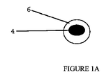
図1、図1A及び1Bについて、吸音バッフル(acoustic absorbing baffle)1はキャリヤー8を含んでいる。図1に於いて、キャリヤー8は、周辺部材5、縦部材2及び横部材4を含む格子(lattice)の形状にある。縦部材2及び横部材4は、キャリヤー8の壁部分を規定する。縦部材2及び横部材4は、それらのそれぞれの交差点で互いに接触状態にあり、周辺部材5と一緒に、キャリヤー8を透過する開口3を規定する。熱発泡性材料6が縦部材2及び横部材4によって形成される壁の少なくとも一方の側面に適用されている。
With reference to FIGS. 1, 1 </ b> A and 1 </ b> B, an acoustic absorbing
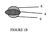
図1A及び図1Bは熱発泡性材料6をキャリヤー8に適用するための代替アプローチを示す。図1Aに示される態様に於いて、熱発泡性材料6は、例示する横部材4をカプセル状に包み、事実上、縦部材2及び横部材4によって規定される壁のそれぞれの対峙側面の上に、熱発泡性材料6を形成している。このような態様に於いて、熱発泡性材料6は縦部材2を同様にカプセル状に包むことができる。代替態様に於いて、縦部材2及び横部材4は、熱発泡性材料6によって部分的にのみ被覆されていてよい。このような態様の例は、図1Bに示され、ここでは、横部材4の2個の対峙側面(キャリヤー8の壁部分の第一の対峙側面及び第二の対峙側面に対応する)は、別々に、熱発泡性材料6によって被覆されている。縦部材6は、この態様に於いて同様に被覆されていてよい。
1A and 1B show an alternative approach for applying the thermally
代替態様に於いて、キャリヤー8は、それ自体、熱発泡性材料から作られている。この場合に於いて、縦部材2及び横部材4(並びに任意的な周辺部材5)は、熱発泡性材料によって作られており、追加の層6は必要でない。
In an alternative embodiment, the carrier 8 is itself made from a thermally foamable material. In this case, the longitudinal member 2 and the transverse member 4 (and optional peripheral member 5) are made of a thermally foamable material and no
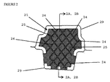
図2、図2A及び図2Bは、本発明の他の面を例示する。図2に於いて、吸音部材21は構造部材29によって規定されるキャビティ内に配置されて、示されている。吸音部材21はキャリヤー28及び熱発泡性材料26を含む。キャリヤー28は壁22を含む。壁22は、第一の対峙側面及び第二の対峙側面を含み、それらの1個のみが図2中に見えている。壁22のそれぞれの側面は、一連の交差している畝(ridge)として図2、図2A及び図2Bに示されている、複数の隆起領域24を含む。隆起領域24は、壁22のそれぞれの表面を、実質的に不連続の区画25に分割している。実質的に不連続の区画25は、それぞれ、0.25〜400mm2の表面積を有する。
2, 2A and 2B illustrate other aspects of the present invention. In FIG. 2, the
本発明の目的のために、図2に於ける区画25のような区画は、(1)それらが、図3に於いて示されるように隆起領域によって隣接する区画から完全に分離されている場合又は(2)それらが、区画の周辺部の、少なくとも50%、更に好ましくは少なくとも75%に沿って伸びている隆起領域によって隣接する区画から分離されている場合、「実質的に不連続」である。隣接する区画の間の完全な分離が、一般的には好ましいが、隣接する区画の間の小さい接続は許容される。従って、例えば畝24は幾つかの態様に於いて不連続であってよく、例えば交互の隆起領域及び平坦領域のラインを形成し、そうして隣接する区画が、畝ライン内に平坦領域が存在する点で接続されるようになっていてよい。
For purposes of the present invention, compartments such as
図2Aは、線2A−2Aに沿って、とられた断面に於けるキャリヤー28を示す。図2Bは、断面内の吸音部材21を示し、熱発泡性材料26のキャリヤー28へ、如何にして適用されるかを示す。熱発泡性材料26は区画25内の壁22の対峙側面に適用されている。畝24は、被覆されないままであるか又は被覆されてとしても、非常に小さい厚さで、畝24の高さの、50%を超えず、好ましくは25%を超えない。図2Bに示される特定の態様に於いて、熱発泡性材料26は畝24の高さよりも幾らか厚い。畝24を被覆されないままで残すことが好ましい。
FIG. 2A shows the
本発明の両方の面を組み合わせる態様が図3及び図3Aに示される。吸音部材31は、構造部材39によって規定されるキャビティ内に配置されて示されている。キャリヤー38は壁32及び周辺部材34を含む。壁22は、第一の対峙側面及び第二の対峙側面を含み、それらの1個のみが図1中に見えている。図示されているように、壁32は、開口33を含み、この開口は、図示される態様に於いて、主として、規則的形状パターンで配列されている。図3及び図3Aに示される態様に於いて、熱発泡性材料40は、壁32のそれぞれの側面に適用され、開口33(これは充填されないままである)及び周辺部材34を除いて、壁32の全表面を本質的に覆っている。熱発泡性材料をキャリヤー38の周辺部材34に適用することも、本発明の範囲内である。
An embodiment that combines both aspects of the present invention is shown in FIGS. 3 and 3A. The
図3及び図3Aに示されるキャリヤーも、隆起領域を含む。図3及び図3Aに於いて、隆起領域は、交差した畝36及び隆起開口ボーダー(border)35の形をとる。畝36及び隆起開口ボーダー35は、一緒に、区画37を規定する。図示される態様に於いて、畝36及び隆起開口ボーダー35の高さは、熱発泡性材料40の厚さにほぼ等しい。前記のように、熱発泡性材料40は、畝36及び隆起開口ボーダー35の高さよりも小さい又は幾らか大きい厚さを有することができる。本発明の第一の面及び第二の面に於いて、開口、例えば図1に於ける開口3及び図3に於ける開口33は、それぞれ、0.8〜320mm2の面積を有する。好ましくは、これらの開口は、それぞれ、3〜80mm2の面積を有する。これらの開口の形状は、一般的には、本発明のために重要ではなく、従って、任意的に選択することができる。従って、これらの開口は、円形、楕円形、多角形、例えば三角形、長方形、六角形、「三日月」形、「星」形又は或る他の形状であってよい。特別の場合に於ける開口は、全部、同じサイズ又は同じ形状であることを必要としない。集合体中の開口は、バッフルの壁の表面積の、約10〜約85%、好ましくは、20〜60%をカバーすることができる。図1に於いて、集合体中の開口3は、キャリヤー8の壁部分の表面積の約60〜75%をカバーする。図3に於いて、集合体中の開口33は、壁32の全表面積の約20〜25%をカバーする。
The carrier shown in FIGS. 3 and 3A also includes a raised region. 3 and 3A, the raised areas take the form of intersecting
開口の特定の配置も特に重要ではない。図1及び図3に示されるように、開口3及び33は、整列された列及び行のパターンで配列されている。熱発泡性材料の発泡の前のバッフルの機械的原形と一致する、開口のランダム配置を含む殆ど任意の代替パターンを使用することができる。幾つかの場合に、流体のより良い排出を与えるために、又は他の理由のために、規定された場所内の開口の少なくとも幾らかをキャリヤーの壁部分の上に配置することが有利であろう。
The particular arrangement of the openings is not particularly important. As shown in FIGS. 1 and 3, the
本発明の第三の面に於いて、隆起領域、例えば図2に於ける隆起領域24、図3に於ける畝36及び図3に於ける隆起開口ボーダー35は、熱発泡性材料の厚さよりも低い、これに等しい又はこれよりも高くてよい。最も好ましくは、このような隆起領域は、高さが熱発泡性材料26の厚さに実質的に等しい(+/−0.5mm)。絶対項に於いて、隆起領域の厚さは、好ましくは約0.5〜20mm、好ましくは1〜12mm、なお更に好ましくは1〜6mmである。実質的に不連続の区画、例えば図2に於いて参照数字25によって、そして図3に於いて参照数字37によって示されるものは、それぞれ、0.25〜400mm2、好ましくは1〜100mm2の表面積を有する。
In the third aspect of the present invention, the raised areas, such as raised
本発明の第一の面及び第二の面に於いて、熱発泡性材料(例えば図1A、図2B及び図3Aに於いて、それぞれ参照数字6、26及び40によって示される)の厚さは、開口のサイズ及び数並びに発泡の際に、熱発泡性材料が、開口(例えば図1及び図3に於いて、それぞれ、開口3及び33)の集合体領域の少なくとも99%、好ましくは100%を充填するまで発泡するような、熱発泡性材料の発泡特性と一緒に選択される。熱発泡性材料は、開口のサイズ及び数並びにこの材料が発泡したとき、それが、開口の集合体表面領域の少なくとも99%を充填できる、この材料の発泡特性を考慮して、十分に厚くなくてはならない。発泡の間に、熱発泡性材料は、その初期体積の少なくとも400%まで(即ち未発泡層のものの4倍である体積まで)からその初期体積の3500%のように大きくまで発泡することができる。好ましい熱発泡性材料は、その初期体積の1000〜3000%又はその初期体積の2000〜3000%まで発泡することができる。
In the first and second aspects of the present invention, the thickness of the thermally foamable material (e.g., indicated by
本発明の全ての面に於いて、発泡前の熱発泡性材料の厚さは、一般的に0.5〜12mm、好ましくは1〜6mmの範囲内である。 In all aspects of the invention, the thickness of the thermally foamable material prior to foaming is generally in the range of 0.5-12 mm, preferably 1-6 mm.
本発明の任意の面の吸音バッフルは追加の機能的特徴を含むことができる。これらの中には、図3に於けるクリップ41のような取付け手段があり、これは、熱発泡性材料が発泡するような時間まで、バッフルを構造物中の所定の位置に一時的に固定するように機能することができる。多くの場合に、熱発泡性材料は、それが発泡されたとき、バッフルを所定の位置に接着するように機能するであろう。
The acoustical baffle of any aspect of the present invention can include additional functional features. Among these are attachment means such as
本発明の種々の面に於いて使用されるキャリヤー(例えばキャリヤー8、28及び38)は、その形状を保持し、熱発泡性材料の層(単数又は複数)の重量を支持するために十分な機械的強度を有する任意の材料からも作ることができる。キャリヤーを作るために使用される材料は、また、熱的に不活性であり、これによって、熱発泡性材料が発泡する条件下で、キャリヤーが溶融、変形又は分解しないことが意味される。例えば、キャリヤーは、金属、セラミック又は有機ポリマーから作ることができる。有機ポリマーは、必要な機械的強度を有するそれを提供することが必要な場合、繊維又は他の強化材料によって強化することができる。キャリヤー8を作るために使用することができる有機ポリマーには、高融点熱可塑性樹脂、例えばポリアミド、ポリイミド、或る種のポリエステルが含まれる。「高融点」によって、熱可塑性樹脂が熱発泡性材料の発泡の間に遭遇する最高温度よりも高い溶融温度又は軟化温度を有することを意味する。
The carriers used in various aspects of the invention (eg,
熱発泡性材料は、室温(約25℃)で固体若しくは高度に粘性の材料であり、それ故、(キャリヤーを使用しない場合)自己支持性であるか、又はキャリヤーを使用するとき、キャリヤーに接着するか若しくは或る中間接着層を介してキャリヤーに接着することができる層に形成することができる、ポリマー組成物又は樹脂組成物から作られる。熱発泡性材料をキャリヤーに機械的に取り付けることも可能であるが、これは、通常あまり好ましくない。このポリマー組成物又は樹脂組成物には、有機ポリマー又はポリマー形成前駆体及び予定の上昇した温度に付されたとき気体を発生する熱活性化性発泡剤が含有されている。120〜250℃の温度にまで加熱されたときに、ポリマー組成物又は樹脂組成物は軟化又は溶融し、発泡剤は気体を発生する。この気体は、軟化又は溶融したポリマー内で気泡を形成し、これは、熱発泡性材料の体積を増加させ、発泡した気泡材料を形成する。この発泡は、しばしば、硬化又は架橋反応を伴い、発泡材料中の安定な気泡構造を作る。 A thermally foamable material is a solid or highly viscous material at room temperature (about 25 ° C.) and is therefore self-supporting (when no carrier is used) or adheres to the carrier when the carrier is used. Or made from a polymer or resin composition that can be formed into a layer that can be adhered to the carrier through some intermediate adhesive layer. Although it is possible to mechanically attach the thermally foamable material to the carrier, this is usually less preferred. The polymer or resin composition contains an organic polymer or polymer-forming precursor and a heat-activatable blowing agent that generates a gas when subjected to a predetermined elevated temperature. When heated to a temperature of 120 to 250 ° C., the polymer composition or resin composition softens or melts and the blowing agent generates gas. This gas forms bubbles in the softened or melted polymer, which increases the volume of the thermally foamable material and forms a foamed cell material. This foaming often involves a curing or cross-linking reaction, creating a stable cellular structure in the foam material.
熱発泡性材料を作るためのポリマー組成物又は樹脂組成物は、追加の成分、例えば活性化剤、触媒、硬化剤、架橋剤、充填剤、可塑剤、湿潤剤、接着改良剤又は粘着付与剤、IR吸収剤、気泡オープナー(cell opener)等を含有していてよい。 The polymer or resin composition for making the heat-foamable material may contain additional components such as activators, catalysts, curing agents, crosslinking agents, fillers, plasticizers, wetting agents, adhesion improvers or tackifiers. , IR absorbers, cell openers and the like.
熱発泡性材料を作るためのポリマー組成物又は樹脂組成物は公知である。熱発泡性樹脂組成物の一つの種類には、発泡剤及び存在していてよいとき他の成分に加えて、1種又はそれ以上のエポキシ樹脂及び1種又はそれ以上のエポキシ硬化剤が含有されている。熱発泡性樹脂組成物の他の種類は、反応し、硬化して、ポリウレタン又はポリウレアフォームを形成する。このような組成物は、典型的には、発泡剤及び存在していてよいとき他の成分に加えて、イソシアネート末端プリポリマー及び1種又はそれ以上のイソシアネート反応性物質が含有されている。ポリマー組成物の第三の種類は、熱可塑性ゴム、例えばスチレン−ブタジエンコポリマーをベースにする。この種類のポリマー組成物は、例えば特許文献5に記載されている。有用なポリマー組成物の更に他の種類は、ポリオレフィン、例えばポリエチレン又はポリエチレンコポリマーをベースにする。これらの種類の熱発泡性材料は、特許文献6、特許文献7、特許文献9、特許文献3、国際特許出願公開第WO2007/117663号明細書、国際特許出願公開第WO2007/117664号明細書及び国際特許出願公開第WO2007/249743号明細書に記載されている。
Polymer compositions or resin compositions for making thermally foamable materials are known. One type of thermally foamable resin composition contains one or more epoxy resins and one or more epoxy curing agents in addition to the foaming agent and other components, if any. ing. Other types of thermally foamable resin compositions react and cure to form polyurethane or polyurea foams. Such compositions typically contain an isocyanate-terminated prepolymer and one or more isocyanate-reactive materials in addition to the blowing agent and other components, if any. A third type of polymer composition is based on thermoplastic rubbers such as styrene-butadiene copolymers. This type of polymer composition is described, for example, in US Pat. Yet another type of useful polymer composition is based on polyolefins such as polyethylene or polyethylene copolymers. These types of thermally foamable materials are disclosed in
吸音部材は、キャリヤーを予備成形し、この予備成形したキャリヤーに熱発泡性材料を適用することによって、便利に製造される。キャリヤーは、その構造の材料を考慮して適切である任意の方法を使用して成形することができる。金属キャリヤーは、型押方法(stamping method)によって便利に形成され、一方、ポリマーキャリヤーは、成形又は押出方法、続く必要な場合の更なる二次成形によって、一層便利に形成される。熱発泡性材料は、オーバーモールディング(overmolding)プロセス又は押出プロセス、再び続く必要な場合の更なる二次成形によって、最も便利に適用される。モールド(金型)表面が、熱発泡性材料のために要求される必要な表面特徴の全部をもたらすように設計できるとき、オーバーモールディングプロセスが特に適している。 The sound absorbing member is conveniently manufactured by preforming a carrier and applying a thermally foamable material to the preformed carrier. The carrier can be molded using any method that is appropriate in view of the material of the structure. The metal carrier is conveniently formed by a stamping method, while the polymer carrier is more conveniently formed by a molding or extrusion method followed by further secondary forming if necessary. Thermally foamable materials are most conveniently applied by an overmolding or extrusion process, followed again by further secondary molding if necessary. Overmolding processes are particularly suitable when the mold surface can be designed to provide all of the necessary surface features required for a thermally foamable material.
本発明の種々の面の吸音部材は、構造キャビティ内のバッファリングの吸音種類及び他の種類を形成するために有用である。特に関心のある構造キャビティは、車両の乗客領域内のノイズを減少するために吸音バッフルが望まれている、車両コンポーネントである。このような車両構造キャビティの例には、乗用車及びトラックの所謂A−、B−及びC−ピラー並びに屋根レール並びに同様の構造物が含まれる。 The sound absorbing members of the various aspects of the present invention are useful for forming buffering sound absorbing types and other types in structural cavities. A structural cavity of particular interest is a vehicle component where a sound absorbing baffle is desired to reduce noise in the passenger area of the vehicle. Examples of such vehicle structural cavities include the so-called A-, B- and C-pillars of passenger cars and trucks, roof rails and similar structures.
バッフルは、吸音バッフル部材をキャビティ内の所定の位置に挿入し、次いで吸音部材を、熱発泡性材料を発泡させるために充分な温度まで加熱することによって形成される。吸音部材は、典型的には、キャビティの縦次元に対して横方向に配向されている。殆どではないとしても多くの場合、熱発泡性材料が発泡した後に、キャビティはバッフルによって密封されるであろう。 The baffle is formed by inserting the sound absorbing baffle member into place in the cavity and then heating the sound absorbing member to a temperature sufficient to foam the thermally foamable material. The sound absorbing member is typically oriented transverse to the longitudinal dimension of the cavity. In many, if not most, cavities will be sealed by baffles after the thermally foamable material has expanded.
吸音バッフル部材は、好ましくは、それが使用されるべきキャビティの断面形状とほぼ同じ断面形状を有する。吸音バッフル部材は、熱発泡性材料の発泡の前には、キャビティ内にぴったりと適合することができる。これらの態様に於いて、発泡工程が完結するまで、吸音バッフル部材を所定の位置に保持するために、単純な摩擦が十分であろう。他の場合に、吸音バッフル部材は、断面がキャビティよりも小さくてよい。このような場合に、発泡工程が完結するまで、吸音バッフル部材を所定の位置に保持するために、吸音バッフル部材をキャビティに固定することが、通常望ましい。機械的手段、例えばクリップ、ピン及び他の締結具を使用することができる。この目的のために、接着剤を同様に使用することができる。 The sound absorbing baffle member preferably has a cross-sectional shape that is approximately the same as the cross-sectional shape of the cavity in which it is to be used. The sound absorbing baffle member can fit snugly within the cavity prior to foaming of the thermally foamable material. In these embodiments, simple friction will be sufficient to hold the sound absorbing baffle member in place until the foaming process is complete. In other cases, the sound absorbing baffle member may be smaller in cross section than the cavity. In such a case, it is usually desirable to fix the sound absorbing baffle member in the cavity in order to hold the sound absorbing baffle member in place until the foaming process is complete. Mechanical means such as clips, pins and other fasteners can be used. For this purpose, an adhesive can be used as well.
熱発泡性材料は、吸音部材を120℃〜250℃の温度まで加熱することによって発泡させられる。好ましい発泡温度は140℃〜210℃である。しかしながら、それぞれの特別の場合に使用される温度は、もちろん、熱発泡性材料を構成するポリマー組成物又は樹脂組成物の組成及び発泡特性に依存するであろう。典型的には、これらの組成物は、予定の温度範囲内で発泡するように配合される。 The thermally foamable material is foamed by heating the sound absorbing member to a temperature of 120 ° C to 250 ° C. A preferred foaming temperature is 140 ° C to 210 ° C. However, the temperature used in each particular case will, of course, depend on the composition and foaming characteristics of the polymer or resin composition making up the thermally foamable material. Typically, these compositions are formulated to foam within a predetermined temperature range.
加熱工程は、熱発泡性材料が発泡して、熱発泡性材料の初期体積の少なくとも400%の体積を有するフォームを形成するまで続けられる。発泡は、初期体積の、好ましくは1000〜3500%、更に好ましくは2000〜3000%までである。熱発泡性材料が、発泡工程の間に架橋及び/又は硬化しなくてはならない場合、加熱工程の温度及び時間は、また、これらのプロセスが起こるために十分なものである。典型的には、加熱工程は、使用される特別の温度、熱発泡性材料の組成、必要とされる発泡の程度、熱発泡性材料の厚さ及びキャリヤーの熱伝導度のような要因に依存して、5〜60分間を必要とするであろう。 The heating process is continued until the thermally foamable material is foamed to form a foam having a volume of at least 400% of the initial volume of the thermally foamable material. Foaming is preferably from 1000 to 3500%, more preferably from 2000 to 3000% of the initial volume. If the thermally foamable material must crosslink and / or cure during the foaming process, the temperature and time of the heating process is also sufficient for these processes to occur. Typically, the heating process depends on factors such as the particular temperature used, the composition of the thermally foamable material, the degree of foaming required, the thickness of the thermally foamable material and the thermal conductivity of the carrier. Would require 5 to 60 minutes.
発泡フォームは、殆どの場合に、バッフルのそれぞれの側面の全表面積を実質的に覆うであろう。キャリヤーが本明細書に記載したような開口を有する本発明の態様に於いて、発泡ホームは、このような開口の集合体表面積の少なくとも99%、好ましくは、100%を覆うであろう。最も好ましくは、発泡フォームはキャビティの断面全体を密封するバッフルを形成するであろう。 The foamed foam will in most cases substantially cover the entire surface area of each side of the baffle. In embodiments of the invention in which the carrier has openings as described herein, the foam home will cover at least 99%, preferably 100%, of the aggregate surface area of such openings. Most preferably, the foam will form a baffle that seals the entire cross section of the cavity.
熱発泡工程を、電気被覆(electrocoating)又はベーク硬化を必要とする他の仕上げのような被覆の熱硬化と同時に実施することが、多くの自動車組立環境に於いて、非常に便利であり、費用効果的である。この被覆は、しばしば、錆及び他の環境損傷に対する保護を有するアセンブリを提供する。このために、被覆材料によって、キャビティの内側を含む、構造物の全ての表面を覆うことが重要である。これは、吸音バッフル部材が、本発明の第一の面に於けるように開口を有するとき助長される。このような場合に、キャビティの組立の間又はキャビティを組み立てた後で、吸音バッフル部材を所望の場所でキャビティの中に挿入することができる。次いで、被覆を、得られる構造物に適用することができる。吸音バッフル部材内の開口によって、被覆がキャビティを通過して流れ、キャビティの内側表面と接触することが可能になる。これは、キャビティの両端が密封されるべきとき又はキャビティの一端のみが開いているとき、特に重要である。同様に、吸音バッフル部材内の開口によって、過剰の被覆が、それがベーク硬化を受ける前に部品から容易に排出されることが可能になる。 Performing the thermal foaming process simultaneously with the thermal curing of the coating, such as electrocoating or other finishes that require bake curing, is very convenient and costly in many automotive assembly environments. It is effective. This coating often provides an assembly with protection against rust and other environmental damage. For this purpose, it is important that the covering material covers all surfaces of the structure, including the inside of the cavity. This is facilitated when the sound absorbing baffle member has an opening as in the first aspect of the present invention. In such a case, the sound absorbing baffle member can be inserted into the cavity at a desired location during or after assembly of the cavity. The coating can then be applied to the resulting structure. An opening in the sound absorbing baffle member allows the coating to flow through the cavity and contact the inner surface of the cavity. This is particularly important when both ends of the cavity are to be sealed or when only one end of the cavity is open. Similarly, the opening in the sound absorbing baffle member allows excess coating to be easily drained from the part before it undergoes bake curing.
次いで、被覆された材料は、加熱工程を受け、その間に、被覆はベーク硬化され、熱発泡性材料は発泡される。吸音バッフル部材中に開口が存在する場合、これらは、これらは熱発泡性材料発泡物によって覆われるようになり、この方法でキャビティを密封する。この密封は、殆どの場合に音響バッフリング(baffling)をもたらし、また、キャビティを密封して、雨水のような液体がキャビティの中に入ること及び腐食を起こすことを防止することができる。 The coated material is then subjected to a heating step, during which the coating is baked and the thermally foamable material is foamed. If openings are present in the sound-absorbing baffle members, they become covered by the thermally foamable material foam and seal the cavity in this way. This seal provides acoustic baffling in most cases and can also seal the cavity to prevent liquids such as rainwater from entering the cavity and causing corrosion.
音響バリヤー部材が、熱発泡性材料の実質的に不連続の区画を含有するとき、熱発泡性材料が、熱発泡性材料が全部で1個の片であるときよりも一層均一に発泡する点で、利益がしばしば見られる。熱発泡性材料が、大きい連続層としてキャリヤーに適用されるとき、一定量の不均一な発泡がしばしば起こることが見出された。これは、音響バリヤー部材を作るためにオーバーモールディング方法が使用されるとき、しばしば事実である。熱発泡性材料を、それぞれ0.25〜400mm2の表面積を有する不連続区画に分断することによって、層の更に均一な発泡が起こることが見出された。本発明は、如何なる理論によっても限定されるものではないが、不均一な発泡は、熱発泡性材料が適用されるとき生じる一定量の不均一配向によって起こされると信じられる。不連続の区画への材料の分断によって、材料中の分離した区画への配向が制限され、それで、区画内で、配向に於ける差が、一般的により小さい。発泡工程の間に不連続区画を加熱するとき、発泡剤が活性化される前に残留配向を除去することが、より良く可能であり、これは一層均一な発泡に至る。 When the acoustic barrier member contains a substantially discontinuous section of thermally foamable material, the thermally foamable material foams more uniformly than when the thermally foamable material is all in one piece. Profits are often seen. It has been found that when a thermally foamable material is applied to a carrier as a large continuous layer, a certain amount of non-uniform foaming often occurs. This is often the case when an overmolding method is used to make an acoustic barrier member. It was found that splitting the thermally foamable material into discrete sections each having a surface area of 0.25 to 400 mm 2 results in a more uniform foaming of the layer. While the present invention is not limited by any theory, it is believed that non-uniform foaming is caused by a certain amount of non-uniform orientation that occurs when a thermally foamable material is applied. Dividing the material into discrete compartments limits the orientation to separate compartments in the material, so that within the compartments, the difference in orientation is generally smaller. When heating the discontinuous compartment during the foaming process, it is better possible to remove the residual orientation before the blowing agent is activated, which leads to a more uniform foaming.
この発泡材料は、殆どの場合に、音響バリヤー(その機能は、キャビティを通して伝達されているノイズ及び振動を、吸収、反射又は遮断することである)として機能する。この発泡材料は、通常、それが主として独立気泡を含有するとき、音響バリヤー材料として良く機能を発揮する。従って、この発泡材料は50〜100%、好ましくは75〜100%の独立気泡を含有することが好ましい。 This foam material functions in most cases as an acoustic barrier, whose function is to absorb, reflect or block noise and vibrations transmitted through the cavity. This foam material usually performs well as an acoustic barrier material when it contains mainly closed cells. Therefore, the foam material preferably contains 50 to 100%, preferably 75 to 100% closed cells.
この発泡材料は、殆どの場合に、音響バリヤー(その機能は、キャビティを通して伝達されているノイズ及び振動を、吸収、反射又は遮断することである)として機能する。この発泡材料は、通常、それが主として独立気泡を含有するとき、音響バリヤー材料として良く機能を発揮する。従って、この発泡材料は50〜100%、好ましくは75〜100%の独立気泡を含有することが好ましい。
以下に、本発明及びその関連態様を記載する。
態様1.熱的に不活性なキャリヤー及び該キャリヤーへ適用された熱発泡性材料を含んでなる未硬化吸音部材であって、
前記キャリヤーが、第一の対峙側面及び第二の対峙側面を有する壁部分並びに該壁部分を貫通して第一の対峙側面から第二の対峙側面まで伸びている開口を含み、その開口が0.5〜20mmの最大寸法を有し、そして該開口が、集合体中で、前記壁部分の表面積の10〜75%を構成し、そして
前記キャリヤー内の開口が、前記熱発泡性材料によって充填されないように、前記熱発泡性材料が前記キャリヤーの両側面に適用され、更に、前記熱発泡性材料が、120〜250℃の範囲内の温度に加熱されたときに発泡することによって膨張して、前記キャリヤー内の開口の領域の少なくとも99%を覆う発泡フォームを形成する、未硬化吸音部材。
態様2.前記熱発泡性材料が、140〜220℃の温度に加熱されたときに、初期体積の2000〜3000%まで発泡する態様1に記載の未硬化吸音部材。
態様3.前記開口が、集合体中で、前記壁部分の表面積の20〜60%を構成する態様1又は2に記載の未硬化吸音部材。
態様4.音響バッフリングをキャビティへ適用する方法であって、
a)態様1、2又は3に記載の未硬化吸音部材を、該キャビティ内に横断方向に配置し、そして
b)前記吸音部材を、120〜250℃の温度に、熱発泡性材料が、その初期体積の少なくとも400%まで発泡するために充分な時間、加熱し、前記キャリヤーのそれぞれの対峙側面の上に、キャリヤーの前記対峙側面の全表面積を実質的に覆い、かつキャリヤー内の開口の領域の少なくとも99%を充填する発泡フォームを生成させる
ことを含んでなる方法。
態様5.工程a)の後で、工程b)の前に、前記キャビティの内部中に、被覆又は腐食処理を適用し、該被覆又は腐食処理体を工程b)の間に硬化させる態様4に記載の方法。
態様6.第一の対峙側面及び第二の対峙側面を有する壁の形の熱発泡性材料並びにこの壁を貫通して第一の対峙側面から第二の対峙側面まで伸びている開口を含んでなる未硬化吸音部材であって、前記開口が0.5〜20mmの最大寸法を有し、前記開口が、集合体中で、この壁部分の表面積の10〜75%を構成し、前記熱発泡性材料が、120〜250℃の範囲内の温度に加熱されたときに発泡することによって膨張して(この熱発泡性材料の発泡によって前記開口が閉じられる)、発泡フォームを形成する未硬化吸音部材。
態様7.前記熱発泡性材料が、140〜220℃の温度に加熱されたときに、初期体積の2000〜3000%まで発泡する態様6に記載の未硬化吸音部材。
態様8.前記開口が、集合体中で、前記壁部分の表面積の20〜60%を構成する態様6又は7に記載の未硬化吸音部材。
態様9.キャビティに音響バッフリングを適用する方法であって、
a)態様6、7又は8に記載の未硬化吸音部材を、前記キャビティ内に横断方向に配置し、そして
b)前記吸音部材を、壁内の開口が熱発泡性材料の発泡によって閉じられるように、熱発泡性材料がその初期体積の少なくとも400%まで発泡するために充分な時間、120〜250℃の温度に、加熱し、そして硬化フォームを生成させる
ことを含んでなる方法。
態様10.工程a)の後で、工程b)の前に、前記キャビティの内部中に、被覆又は腐食処理を、適用し、該被覆又は腐食処理体を工程b)の間に硬化させる態様9に記載の方法。
態様11.熱的に不活性のキャリヤー及び該キャリヤーに適用された、120〜250℃の範囲内の温度に加熱されたときに、硬化し、そしてその初期体積の少なくとも400%まで発泡して発泡フォームを形成する熱発泡性材料を含んでなる未硬化吸音部材であって、
前記キャリヤーが、対峙表面を有する壁部分を含み、対峙表面の少なくとも1個が、該表面を、それぞれ、0.25〜400mm 2 の表面積を有する実質的に不連続の区画に、分割する隆起領域を含み、そして
前記熱発泡性材料の少なくとも一部が、前記隆起領域によって規定される実質的に不連続の区画内のキャリヤーの少なくとも1個の表面に適用されて、前記キャリヤーの表面上に熱発泡性材料の不連続の区画を形成する未硬化吸音部材。
態様12.前記キャリヤーが、第一の対峙側面及び第二の対峙側面並びに前記壁部分を貫通して第一の対峙側面から第二の対峙側面まで伸びている開口を有し、該開口が0.5〜20mmの最大寸法を有し、該開口が、集合体中で、前記壁部分の表面積の10〜75%を構成する態様11に記載の吸音部材。
態様13.前記開口の少なくとも一部が隆起開口ボーダーを有する態様12に記載の吸音部材。
態様14.キャビティへ音響バッフリングを適用する方法であって、
a)態様11、12又は13に記載の未硬化吸音部材を、前記キャビティ内に横断方向に配置し、そして
b)前記吸音部材を、熱発泡性材料の不連続層が、その初期体積の少なくとも400%まで発泡するために充分な時間、120〜250℃の温度に、加熱し、そしてキャリヤーの少なくとも1個の側面上に、該キャリヤーの該側面の全表面積を実質的に覆う発泡フォームを生成させる
ことを含んでなる方法。
This foam material functions in most cases as an acoustic barrier, whose function is to absorb, reflect or block noise and vibrations transmitted through the cavity. This foam material usually performs well as an acoustic barrier material when it contains mainly closed cells. Therefore, the foam material preferably contains 50 to 100%, preferably 75 to 100% closed cells.
The present invention and related aspects are described below.
The carrier includes a wall portion having a first opposing side and a second opposing side and an opening extending through the wall portion from the first opposing side to the second opposing side, the opening being zero. Have a maximum dimension of 5 to 20 mm, and the openings constitute 10 to 75% of the surface area of the wall portion in the assembly, and
The thermally foamable material is applied to both sides of the carrier so that openings in the carrier are not filled by the thermally foamable material, and the thermally foamable material is in the range of 120-250 ° C. An uncured sound absorbing member that expands by foaming when heated to a temperature to form a foam foam covering at least 99% of the area of the opening in the carrier.
Aspect 2. The uncured sound absorbing member according to
a) the uncured sound absorbing member according to
b) heating the sound absorbing member to a temperature of 120-250 ° C. for a time sufficient for the thermally foamable material to foam to at least 400% of its initial volume, on each opposite side of the carrier; Producing a foam foam that substantially covers the entire surface area of the opposite side of the carrier and fills at least 99% of the open area in the carrier.
A method comprising that.
Aspect 5 A method according to
Aspect 7. The uncured sound absorbing member according to
Aspect 8 The uncured sound absorbing member according to
Aspect 9. A method of applying acoustic buffing to a cavity,
a) the uncured sound absorbing member according to
b) at 120-250 ° C. for a time sufficient for the thermally foamable material to foam to at least 400% of its initial volume, such that the opening in the wall is closed by foaming of the thermally foamable material. Heat to temperature, and produce a cured foam
A method comprising that.
Aspect 10 10. Aspect 9 wherein after step a) and before step b), a coating or corrosion treatment is applied in the interior of the cavity and the coating or corrosion treated body is cured during step b). Method.
Aspect 11 Thermally inert carrier and applied to the carrier, when heated to a temperature in the range of 120-250 ° C., cures and foams to at least 400% of its initial volume to form a foamed foam An uncured sound absorbing member comprising a thermally foamable material,
The carrier includes a wall portion having an opposing surface, wherein at least one of the opposing surfaces divides the surface into substantially discontinuous sections each having a surface area of 0.25 to 400 mm 2. Including, and
At least a portion of the thermally foamable material is applied to at least one surface of the carrier in a substantially discontinuous compartment defined by the raised region, so that the thermally foamable material on the surface of the carrier. An uncured sound absorbing member that forms discontinuous compartments.
Aspect 12 The carrier has first and second opposing sides and an opening extending through the wall portion from the first opposing side to the second opposing side, the opening being 0.5 to The sound-absorbing member according to aspect 11, having a maximum dimension of 20 mm, wherein the opening constitutes 10 to 75% of the surface area of the wall portion in the assembly.
Aspect 13 The sound absorbing member according to aspect 12, wherein at least a part of the opening has a raised opening border.
Aspect 14. A method of applying acoustic buffing to a cavity,
a) the uncured sound absorbing member according to embodiment 11, 12 or 13 is disposed transversely within the cavity; and
b) heating the sound absorbing member to a temperature of 120-250 ° C. for a time sufficient for the discontinuous layer of thermally foamable material to foam to at least 400% of its initial volume, and at least one of the carriers Producing foamed foam on the side of the carrier substantially covering the entire surface area of the side of the carrier
A method comprising that.
Claims (14)
前記キャリヤーが、第一の対峙側面及び第二の対峙側面を有する壁部分並びに該壁部分を貫通して第一の対峙側面から第二の対峙側面まで伸びている開口を含み、その開口が0.5〜20mmの最大寸法を有し、そして該開口が、集合体中で、前記壁部分の表面積の10〜75%を構成し、そして
前記キャリヤー内の開口が、前記熱発泡性材料によって充填されないように、前記熱発泡性材料が前記キャリヤーの両側面に適用され、更に、前記熱発泡性材料が、120〜250℃の範囲内の温度に加熱されたときに発泡することによって膨張して、前記キャリヤー内の開口の領域の少なくとも99%を覆う発泡フォームを形成する、未硬化吸音部材。 An uncured sound absorbing member comprising a thermally inert carrier and a thermally foamable material applied to the carrier,
The carrier includes a wall portion having a first opposing side and a second opposing side and an opening extending through the wall portion from the first opposing side to the second opposing side, the opening being zero. Having a maximum dimension of 5-20 mm, and the openings constitute 10-75% of the surface area of the wall portion in the assembly, and the openings in the carrier are filled with the thermally foamable material The thermally foamable material is applied to both sides of the carrier, and the thermally foamable material expands by foaming when heated to a temperature in the range of 120-250 ° C. An uncured sound absorbing member that forms a foam that covers at least 99% of the area of the opening in the carrier.
a)請求項1、2又は3に記載の未硬化吸音部材を、該キャビティ内に横断方向に配置し、そして
b)前記吸音部材を、120〜250℃の温度に、熱発泡性材料が、その初期体積の少なくとも400%まで発泡するために充分な時間、加熱し、前記キャリヤーのそれぞれの対峙側面の上に、キャリヤーの前記対峙側面の全表面積を実質的に覆い、かつキャリヤー内の開口の領域の少なくとも99%を充填する発泡フォームを生成させる
ことを含んでなる方法。 Applying acoustic buffing to a cavity, comprising:
a) the uncured sound absorbing member according to claim 1, 2 or 3 is disposed transversely in the cavity; and b) the sound absorbing member is at a temperature of 120-250 ° C. Heat for a time sufficient to foam to at least 400% of its initial volume, substantially covering the entire surface area of the opposite side of the carrier over each opposite side of the carrier, and the opening in the carrier. Producing a foam that fills at least 99% of the area.
a)請求項6、7又は8に記載の未硬化吸音部材を、前記キャビティ内に横断方向に配置し、そして
b)前記吸音部材を、壁内の開口が熱発泡性材料の発泡によって閉じられるように、熱発泡性材料がその初期体積の少なくとも400%まで発泡するために充分な時間、120〜250℃の温度に、加熱し、そして硬化フォームを生成させる
ことを含んでなる方法。 A method of applying acoustic buffing to a cavity,
a) the uncured sound-absorbing member according to claim 6, 7 or 8 is disposed transversely in the cavity; and b) the sound-absorbing member is closed in the wall by foaming of a thermally foamable material. Thus, the method comprising heating to a temperature of 120-250 ° C. for a time sufficient to cause the thermally foamable material to foam to at least 400% of its initial volume and producing a cured foam.
前記キャリヤーが、対峙表面を有する壁部分を含み、対峙表面の少なくとも1個が、該表面を、それぞれ、0.25〜400mm2の表面積を有する実質的に不連続の区画に、分割する隆起領域を含み、そして
前記熱発泡性材料の少なくとも一部が、前記隆起領域によって規定される実質的に不連続の区画内のキャリヤーの少なくとも1個の表面に適用されて、前記キャリヤーの表面上に熱発泡性材料の不連続の区画を形成する未硬化吸音部材。 Thermally inert carrier and applied to the carrier, when heated to a temperature in the range of 120-250 ° C., cures and foams to at least 400% of its initial volume to form a foamed foam An uncured sound absorbing member comprising a thermally foamable material,
The carrier includes a wall portion having an opposing surface, wherein at least one of the opposing surfaces divides the surface into substantially discontinuous sections each having a surface area of 0.25 to 400 mm 2. And at least a portion of the thermally foamable material is applied to at least one surface of the carrier in a substantially discontinuous compartment defined by the raised region to cause heat on the surface of the carrier. An uncured sound absorbing member that forms discontinuous sections of foamable material.
a)請求項11、12又は13に記載の未硬化吸音部材を、前記キャビティ内に横断方向に配置し、そして
b)前記吸音部材を、熱発泡性材料の不連続層が、その初期体積の少なくとも400%まで発泡するために充分な時間、120〜250℃の温度に、加熱し、そしてキャリヤーの少なくとも1個の側面上に、該キャリヤーの該側面の全表面積を実質的に覆う発泡フォームを生成させる
ことを含んでなる方法。 A method of applying acoustic buffing to a cavity,
a) the uncured sound-absorbing member according to claim 11, 12 or 13 is disposed transversely in the cavity; and b) the sound-absorbing member comprises a discontinuous layer of thermally foamable material of its initial volume. A foamed foam heated to a temperature of 120-250 ° C. for a time sufficient to foam to at least 400% and covering substantially the entire surface area of the side of the carrier on at least one side of the carrier. A method comprising generating.
Applications Claiming Priority (1)
| Application Number | Priority Date | Filing Date | Title |
|---|---|---|---|
| PCT/CN2008/073201 WO2010060241A1 (en) | 2008-11-26 | 2008-11-26 | Acoustic baffle members and methods for applying acoustic baffles in cavities |
Publications (1)
| Publication Number | Publication Date |
|---|---|
| JP2012509806A true JP2012509806A (en) | 2012-04-26 |
Family
ID=42225190
Family Applications (2)
| Application Number | Title | Priority Date | Filing Date |
|---|---|---|---|
| JP2011537812A Ceased JP2012509806A (en) | 2008-11-26 | 2008-11-26 | Sound absorbing baffle member and method for applying sound absorbing baffle in cavity |
| JP2011537832A Ceased JP2012510082A (en) | 2008-11-26 | 2009-11-26 | Sound absorbing baffle member and method for applying sound absorbing baffle to cavity |
Family Applications After (1)
| Application Number | Title | Priority Date | Filing Date |
|---|---|---|---|
| JP2011537832A Ceased JP2012510082A (en) | 2008-11-26 | 2009-11-26 | Sound absorbing baffle member and method for applying sound absorbing baffle to cavity |
Country Status (5)
| Country | Link |
|---|---|
| US (2) | US8449701B2 (en) |
| JP (2) | JP2012509806A (en) |
| KR (2) | KR20110091876A (en) |
| CN (1) | CN102224038B (en) |
| WO (2) | WO2010060241A1 (en) |
Families Citing this family (25)
| Publication number | Priority date | Publication date | Assignee | Title |
|---|---|---|---|---|
| KR20160085363A (en) * | 2008-07-29 | 2016-07-15 | 다우 글로벌 테크놀로지스 엘엘씨 | Toughened expandable epoxy resins for stiffening and energy dissipation in automotive cavities |
| BR112014018055A8 (en) * | 2012-03-20 | 2017-07-11 | Zephyros Inc | DEFLECTOR ASSEMBLY |
| EP3483046A1 (en) * | 2012-06-08 | 2019-05-15 | Zephyros Inc. | Baffle with expanding material |
| MX363656B (en) * | 2012-12-18 | 2019-03-28 | Henkel Ag & Co Kgaa | Device and method for providing structural reinforcement and/or sound and vibration control within the cavities of hollow members of a vehicle body. |
| EP4145441A1 (en) * | 2012-12-21 | 2023-03-08 | Sika Technology AG | Insulating element, expanded insulating element, use of such an element and method for insulating |
| CN105358301B (en) * | 2013-04-26 | 2017-05-03 | 泽费罗斯股份有限公司 | Activatable material and carrier attachment |
| JP6235869B2 (en) * | 2013-11-01 | 2017-11-22 | 八千代工業株式会社 | Wave plate fixing structure in fuel tank |
| CN107000271A (en) * | 2014-11-14 | 2017-08-01 | 泽菲罗斯公司 | Multiple injection moulding process and product |
| CA2968549C (en) | 2014-11-24 | 2020-03-10 | Ppg Industries Ohio, Inc. | Coreactive materials and methods for three-dimensional printing |
| US9764769B2 (en) | 2015-02-09 | 2017-09-19 | Honda Motor Co., Ltd. | Vehicle frame structural member assembly and method |
| CN113910724A (en) * | 2016-03-02 | 2022-01-11 | 泽菲罗斯有限公司 | Discontinuous net structure |
| EP3445642B1 (en) | 2016-04-22 | 2021-06-16 | Sika Technology AG | Insulation element |
| EP3254939B1 (en) | 2016-06-10 | 2021-09-01 | Sika Technology AG | Baffle |
| FR3067275B1 (en) | 2017-06-07 | 2022-08-12 | Timothee Boitouzet | PROCESS FOR PARTIAL DELIGNIFICATION BY SUPERCRITICAL OR SUBCRITICAL ROUTE AND FILLING OF A LIGNO-CELLULOSIC MATERIAL |
| CN107399283A (en) * | 2017-08-01 | 2017-11-28 | 湖北天运消音防振新材料有限公司 | A kind of sound-absorbing cotton |
| KR102643930B1 (en) * | 2018-05-30 | 2024-03-05 | 나이키 이노베이트 씨.브이. | Footwear sole structure with bladder |
| US11697233B2 (en) * | 2018-06-26 | 2023-07-11 | Nissan Motor Co., Ltd. | Composite |
| KR20210050513A (en) * | 2018-08-31 | 2021-05-07 | 시카 테크놀러지 아게 | Devices for reinforcing, sealing or damping structural elements |
| KR102618225B1 (en) * | 2018-08-31 | 2023-12-27 | 시카 테크놀러지 아게 | Systems for shielding structural elements |
| JP6925082B2 (en) * | 2018-09-14 | 2021-08-25 | MT−Tec合同会社 | Sound absorbing material for automobiles |
| FR3086196B1 (en) | 2018-09-20 | 2022-12-16 | Sas Woodoo | PART MADE OF LIGNO-CELLULOSIC MATERIAL AND METHOD FOR MANUFACTURING SUCH A PART |
| US10783867B2 (en) * | 2018-11-08 | 2020-09-22 | Apple Inc. | Acoustic filler including acoustically active beads and expandable filler |
| CN113573948A (en) * | 2019-02-08 | 2021-10-29 | 泰佛产品服务与创新公司 | Sound-insulating screen for the engine compartment of a motor vehicle |
| USD950472S1 (en) * | 2019-04-24 | 2022-05-03 | Valhalla Off-road Research Inc. | Storage panel |
| US11465564B2 (en) * | 2019-05-28 | 2022-10-11 | Honda Motor Co., Ltd. | Parcel shelf for sound management in vehicle |
Citations (2)
| Publication number | Priority date | Publication date | Assignee | Title |
|---|---|---|---|---|
| US6093358A (en) * | 1998-01-27 | 2000-07-25 | Lear Corporation | Method of making an expandable gap filling product |
| WO2008043385A1 (en) * | 2006-10-13 | 2008-04-17 | Henkel Ag & Co. Kgaa | Acoustic absorbing member with different types of pores |
Family Cites Families (22)
| Publication number | Priority date | Publication date | Assignee | Title |
|---|---|---|---|---|
| US4759000A (en) | 1985-06-13 | 1988-07-19 | Reitz Ronald P | Acoustic energy absorbing material |
| JPH02267034A (en) * | 1989-04-07 | 1990-10-31 | Morita Sangyo Kk | Heat insulating mat material for vehicle trunk room |
| JPH0722974B2 (en) * | 1989-04-07 | 1995-03-15 | 森田産業株式会社 | Net sponge sheet |
| US5266133A (en) | 1993-02-17 | 1993-11-30 | Sika Corporation | Dry expansible sealant and baffle composition and product |
| US5504281A (en) | 1994-01-21 | 1996-04-02 | Minnesota Mining And Manufacturing Company | Perforated acoustical attenuators |
| US5506025A (en) * | 1995-01-09 | 1996-04-09 | Sika Corporation | Expandable baffle apparatus |
| JP2964327B2 (en) * | 1997-12-24 | 1999-10-18 | 森田産業株式会社 | Net-shaped sponge sheet |
| US6114004A (en) | 1998-01-26 | 2000-09-05 | Cydzik; Edward A. | Cavity sealing article |
| US6146565A (en) | 1998-07-15 | 2000-11-14 | Noble Polymers, L.L.C. | Method of forming a heat expandable acoustic baffle |
| US6382635B1 (en) * | 2000-03-17 | 2002-05-07 | Sika Corporation | Double walled baffle |
| JP2002099281A (en) * | 2000-09-25 | 2002-04-05 | Neoex Lab Inc | Hollow chamber shutter of hollow structure |
| FR2826093B1 (en) * | 2001-06-15 | 2003-08-08 | Peugeot Citroen Automobiles Sa | METHOD FOR ACOUSTICALLY ISOLATING A HOLLOW BODY, SUCH AS A BODY PART OF A MOTOR VEHICLE |
| GB0211287D0 (en) * | 2002-05-17 | 2002-06-26 | L & L Products Inc | Improved baffle precursors |
| JP4159855B2 (en) * | 2002-10-31 | 2008-10-01 | 共和産業株式会社 | Hollow chamber breaker for hollow structure |
| DE102004001081B4 (en) * | 2004-01-05 | 2013-02-14 | Airbus Operations Gmbh | Insulation structure for the internal insulation of a vehicle |
| JP2007519556A (en) * | 2004-01-12 | 2007-07-19 | ダウ グローバル テクノロジーズ インコーポレイティド | Automotive dash insulator containing viscoelastic foam |
| GB2415658A (en) | 2004-06-21 | 2006-01-04 | L & L Products Inc | An overmoulding process |
| US20060065483A1 (en) | 2004-09-29 | 2006-03-30 | L&L Products, Inc. | Baffle with flow-through medium |
| DE102005013311A1 (en) | 2005-03-22 | 2006-10-05 | Federal-Mogul Sealing Systems Gmbh | Shielding element for motor vehicles |
| US7926179B2 (en) | 2005-08-04 | 2011-04-19 | Zephyros, Inc. | Reinforcements, baffles and seals with malleable carriers |
| CA2648474A1 (en) | 2006-04-06 | 2007-10-18 | Dow Global Technologies Inc. | Expandable polyolefin compositions and insulated vehicle parts containing expanded polyolefin compositions |
| US8163116B2 (en) * | 2006-05-09 | 2012-04-24 | Zephyros, Inc. | Joints and a system and method of forming the joints |
-
2008
- 2008-11-26 US US13/129,136 patent/US8449701B2/en active Active
- 2008-11-26 JP JP2011537812A patent/JP2012509806A/en not_active Ceased
- 2008-11-26 KR KR1020117014466A patent/KR20110091876A/en not_active Application Discontinuation
- 2008-11-26 WO PCT/CN2008/073201 patent/WO2010060241A1/en active Application Filing
- 2008-11-26 CN CN2008801321110A patent/CN102224038B/en active Active
-
2009
- 2009-11-26 US US13/129,133 patent/US8535463B2/en active Active
- 2009-11-26 JP JP2011537832A patent/JP2012510082A/en not_active Ceased
- 2009-11-26 KR KR1020117014467A patent/KR20110097894A/en not_active Application Discontinuation
- 2009-11-26 WO PCT/CN2009/075142 patent/WO2010060381A1/en active Application Filing
Patent Citations (2)
| Publication number | Priority date | Publication date | Assignee | Title |
|---|---|---|---|---|
| US6093358A (en) * | 1998-01-27 | 2000-07-25 | Lear Corporation | Method of making an expandable gap filling product |
| WO2008043385A1 (en) * | 2006-10-13 | 2008-04-17 | Henkel Ag & Co. Kgaa | Acoustic absorbing member with different types of pores |
Also Published As
| Publication number | Publication date |
|---|---|
| JP2012510082A (en) | 2012-04-26 |
| US20110277911A1 (en) | 2011-11-17 |
| WO2010060381A1 (en) | 2010-06-03 |
| KR20110091876A (en) | 2011-08-16 |
| US8535463B2 (en) | 2013-09-17 |
| CN102224038A (en) | 2011-10-19 |
| KR20110097894A (en) | 2011-08-31 |
| WO2010060241A1 (en) | 2010-06-03 |
| US20110290585A1 (en) | 2011-12-01 |
| CN102224038B (en) | 2013-10-23 |
| US8449701B2 (en) | 2013-05-28 |
Similar Documents
| Publication | Publication Date | Title |
|---|---|---|
| JP2012509806A (en) | Sound absorbing baffle member and method for applying sound absorbing baffle in cavity | |
| US6926784B2 (en) | Sound absorption system for automotive vehicles | |
| US8276974B2 (en) | Noise reduction member and system | |
| US8215704B2 (en) | Acoustic baffle | |
| US8079442B2 (en) | Acoustic baffle | |
| US7077460B2 (en) | Reinforcement system utilizing a hollow carrier | |
| US20050285292A1 (en) | Laminar mouldings | |
| KR101503546B1 (en) | Sound―absorbing baffle for sealing a hollow space | |
| US20040036317A1 (en) | Vibrational reduction system for automotive vehicles | |
| US20050087899A1 (en) | Baffle and method of forming same | |
| US20090001758A1 (en) | Expandable insert for hollow structure | |
| SK11772000A3 (en) | Three dimensional composite joint reinforcement for an automotive vehicle | |
| KR20080034493A (en) | Reinforcements, baffles and seals with malleable carriers | |
| WO2009049886A1 (en) | Multifunctional vehicle components | |
| EP2080192B1 (en) | Acoustic absorbing member with open and closed pores | |
| CN102224540B (en) | Acoustic baffle members and methods for applying acoustic baffles in cavities | |
| WO2012143305A1 (en) | Improvements in or relating to baffles |
Legal Events
| Date | Code | Title | Description |
|---|---|---|---|
| A131 | Notification of reasons for refusal |
Free format text: JAPANESE INTERMEDIATE CODE: A131 Effective date: 20130326 |
|
| A521 | Written amendment |
Free format text: JAPANESE INTERMEDIATE CODE: A523 Effective date: 20130620 |
|
| A01 | Written decision to grant a patent or to grant a registration (utility model) |
Free format text: JAPANESE INTERMEDIATE CODE: A01 Effective date: 20131203 |
|
| A045 | Written measure of dismissal of application [lapsed due to lack of payment] |
Free format text: JAPANESE INTERMEDIATE CODE: A045 Effective date: 20140422 |