EP3483046A1 - Baffle with expanding material - Google Patents
Baffle with expanding material Download PDFInfo
- Publication number
- EP3483046A1 EP3483046A1 EP18191120.7A EP18191120A EP3483046A1 EP 3483046 A1 EP3483046 A1 EP 3483046A1 EP 18191120 A EP18191120 A EP 18191120A EP 3483046 A1 EP3483046 A1 EP 3483046A1
- Authority
- EP
- European Patent Office
- Prior art keywords
- carrier
- baffle
- expandable material
- voids
- expandable
- Prior art date
- Legal status (The legal status is an assumption and is not a legal conclusion. Google has not performed a legal analysis and makes no representation as to the accuracy of the status listed.)
- Withdrawn
Links
Images
Classifications
-
- B—PERFORMING OPERATIONS; TRANSPORTING
- B29—WORKING OF PLASTICS; WORKING OF SUBSTANCES IN A PLASTIC STATE IN GENERAL
- B29D—PRODUCING PARTICULAR ARTICLES FROM PLASTICS OR FROM SUBSTANCES IN A PLASTIC STATE
- B29D99/00—Subject matter not provided for in other groups of this subclass
- B29D99/0053—Producing sealings
-
- B—PERFORMING OPERATIONS; TRANSPORTING
- B32—LAYERED PRODUCTS
- B32B—LAYERED PRODUCTS, i.e. PRODUCTS BUILT-UP OF STRATA OF FLAT OR NON-FLAT, e.g. CELLULAR OR HONEYCOMB, FORM
- B32B37/00—Methods or apparatus for laminating, e.g. by curing or by ultrasonic bonding
- B32B37/12—Methods or apparatus for laminating, e.g. by curing or by ultrasonic bonding characterised by using adhesives
-
- B—PERFORMING OPERATIONS; TRANSPORTING
- B32—LAYERED PRODUCTS
- B32B—LAYERED PRODUCTS, i.e. PRODUCTS BUILT-UP OF STRATA OF FLAT OR NON-FLAT, e.g. CELLULAR OR HONEYCOMB, FORM
- B32B37/00—Methods or apparatus for laminating, e.g. by curing or by ultrasonic bonding
- B32B37/14—Methods or apparatus for laminating, e.g. by curing or by ultrasonic bonding characterised by the properties of the layers
- B32B37/144—Methods or apparatus for laminating, e.g. by curing or by ultrasonic bonding characterised by the properties of the layers using layers with different mechanical or chemical conditions or properties, e.g. layers with different thermal shrinkage, layers under tension during bonding
-
- B—PERFORMING OPERATIONS; TRANSPORTING
- B32—LAYERED PRODUCTS
- B32B—LAYERED PRODUCTS, i.e. PRODUCTS BUILT-UP OF STRATA OF FLAT OR NON-FLAT, e.g. CELLULAR OR HONEYCOMB, FORM
- B32B37/00—Methods or apparatus for laminating, e.g. by curing or by ultrasonic bonding
- B32B37/14—Methods or apparatus for laminating, e.g. by curing or by ultrasonic bonding characterised by the properties of the layers
- B32B37/24—Methods or apparatus for laminating, e.g. by curing or by ultrasonic bonding characterised by the properties of the layers with at least one layer not being coherent before laminating, e.g. made up from granular material sprinkled onto a substrate
-
- B—PERFORMING OPERATIONS; TRANSPORTING
- B32—LAYERED PRODUCTS
- B32B—LAYERED PRODUCTS, i.e. PRODUCTS BUILT-UP OF STRATA OF FLAT OR NON-FLAT, e.g. CELLULAR OR HONEYCOMB, FORM
- B32B38/00—Ancillary operations in connection with laminating processes
- B32B38/0004—Cutting, tearing or severing, e.g. bursting; Cutter details
-
- B—PERFORMING OPERATIONS; TRANSPORTING
- B60—VEHICLES IN GENERAL
- B60R—VEHICLES, VEHICLE FITTINGS, OR VEHICLE PARTS, NOT OTHERWISE PROVIDED FOR
- B60R13/00—Elements for body-finishing, identifying, or decorating; Arrangements or adaptations for advertising purposes
- B60R13/06—Sealing strips
-
- B—PERFORMING OPERATIONS; TRANSPORTING
- B60—VEHICLES IN GENERAL
- B60R—VEHICLES, VEHICLE FITTINGS, OR VEHICLE PARTS, NOT OTHERWISE PROVIDED FOR
- B60R13/00—Elements for body-finishing, identifying, or decorating; Arrangements or adaptations for advertising purposes
- B60R13/08—Insulating elements, e.g. for sound insulation
- B60R13/0815—Acoustic or thermal insulation of passenger compartments
-
- B—PERFORMING OPERATIONS; TRANSPORTING
- B62—LAND VEHICLES FOR TRAVELLING OTHERWISE THAN ON RAILS
- B62D—MOTOR VEHICLES; TRAILERS
- B62D21/00—Understructures, i.e. chassis frame on which a vehicle body may be mounted
- B62D21/09—Means for mounting load bearing surfaces
-
- B—PERFORMING OPERATIONS; TRANSPORTING
- B62—LAND VEHICLES FOR TRAVELLING OTHERWISE THAN ON RAILS
- B62D—MOTOR VEHICLES; TRAILERS
- B62D29/00—Superstructures, understructures, or sub-units thereof, characterised by the material thereof
- B62D29/001—Superstructures, understructures, or sub-units thereof, characterised by the material thereof characterised by combining metal and synthetic material
- B62D29/002—Superstructures, understructures, or sub-units thereof, characterised by the material thereof characterised by combining metal and synthetic material a foamable synthetic material or metal being added in situ
-
- B—PERFORMING OPERATIONS; TRANSPORTING
- B62—LAND VEHICLES FOR TRAVELLING OTHERWISE THAN ON RAILS
- B62D—MOTOR VEHICLES; TRAILERS
- B62D29/00—Superstructures, understructures, or sub-units thereof, characterised by the material thereof
- B62D29/001—Superstructures, understructures, or sub-units thereof, characterised by the material thereof characterised by combining metal and synthetic material
- B62D29/005—Superstructures, understructures, or sub-units thereof, characterised by the material thereof characterised by combining metal and synthetic material preformed metal and synthetic material elements being joined together, e.g. by adhesives
-
- B—PERFORMING OPERATIONS; TRANSPORTING
- B32—LAYERED PRODUCTS
- B32B—LAYERED PRODUCTS, i.e. PRODUCTS BUILT-UP OF STRATA OF FLAT OR NON-FLAT, e.g. CELLULAR OR HONEYCOMB, FORM
- B32B2305/00—Condition, form or state of the layers or laminate
- B32B2305/02—Cellular or porous
- B32B2305/022—Foam
-
- B—PERFORMING OPERATIONS; TRANSPORTING
- B32—LAYERED PRODUCTS
- B32B—LAYERED PRODUCTS, i.e. PRODUCTS BUILT-UP OF STRATA OF FLAT OR NON-FLAT, e.g. CELLULAR OR HONEYCOMB, FORM
- B32B2307/00—Properties of the layers or laminate
- B32B2307/10—Properties of the layers or laminate having particular acoustical properties
- B32B2307/102—Insulating
-
- B—PERFORMING OPERATIONS; TRANSPORTING
- B32—LAYERED PRODUCTS
- B32B—LAYERED PRODUCTS, i.e. PRODUCTS BUILT-UP OF STRATA OF FLAT OR NON-FLAT, e.g. CELLULAR OR HONEYCOMB, FORM
- B32B2581/00—Seals; Sealing equipment; Gaskets
-
- Y—GENERAL TAGGING OF NEW TECHNOLOGICAL DEVELOPMENTS; GENERAL TAGGING OF CROSS-SECTIONAL TECHNOLOGIES SPANNING OVER SEVERAL SECTIONS OF THE IPC; TECHNICAL SUBJECTS COVERED BY FORMER USPC CROSS-REFERENCE ART COLLECTIONS [XRACs] AND DIGESTS
- Y10—TECHNICAL SUBJECTS COVERED BY FORMER USPC
- Y10T—TECHNICAL SUBJECTS COVERED BY FORMER US CLASSIFICATION
- Y10T156/00—Adhesive bonding and miscellaneous chemical manufacture
- Y10T156/10—Methods of surface bonding and/or assembly therefor
- Y10T156/1052—Methods of surface bonding and/or assembly therefor with cutting, punching, tearing or severing
- Y10T156/1056—Perforating lamina
Definitions
- the present invention relates generally to a baffling and/or sealing member that includes an expandable material and a carrier with voids and spaced-apart members formed of varying materials to reduce weight, material, and cost, and to improve sound attenuation characteristics.
- the present invention meets the aforementioned needs by providing a baffle comprising a carrier having an interior body portion with a plurality of spaced apart members providing voids and a peripheral rim substantially surrounding the interior body portion.
- the device further includes a thermally expandable sealing material disposed on the carrier in an amount and of a material sufficient for thermally expanding to fill a vehicle cavity and cover the interior body portion and each of the voids.
- the expandable material may be a material that is elastically deformable without rupture for forming a mechanical interconnection with a wall of a cavity of a vehicle.
- the carrier may be a continuous surface that is substantially free of protuberances.
- the expandable material may be attached to a face of the carrier. The end of the carrier and end of the expandable material may not be co-extensive.
- the expandable material may extend laterally to a portion short of a terminating edge of the carrier.
- the expandable material may extend to a location that is at least 1mm from a terminating edge of the carrier.
- the baffle may include a fastener formed as a nylon clip integrally formed with the carrier.
- the baffle may be formed in a two step molding process in a rotary mold.
- the baffle may be formed by a die-cutting process.
- the baffle may be formed by processing steps that are free of any die-cutting process.
- An edge of the carrier may be formed surrounding each void and the expandable material located about the voids is not co-extensive with the edge of the carrier surrounding each void.
- the expandable material may be co-extensive with the peripheral rim of the carrier.
- the carrier and expandable material may be formed to each include the same number of voids.
- the carrier and expandable material may be formed to include differing numbers of voids.
- the carrier may be formed with at least four voids.
- the teachings herein further contemplate a method for forming the baffles described herein comprising die cutting the carrier to form the voids in the carrier and die cutting the expandable material to form the voids in the expandable material so that the voids in the carrier material and the voids in the expandable material are located in corresponding locations with one another.
- the method may further include a step of locating the expandable material in direct planar contact with the carrier so that the voids in the expandable material are in an overlying relationship with the voids of the carrier.
- the method may include a step of locating the baffle within a vehicle cavity.
- the method may include a step of exposing the expandable material to heat so that the expandable material expands.
- the invention herein contemplates a baffle for the sealing of cavities with a carrier having an interior body portion with a plurality of spaced-apart members providing voids and one or more expandable sealing materials.
- the present invention allows for improved baffling and sealing of a cavity using substantially less material than a traditional baffle by providing voids in one or more of the carrier and the expandable material.
- the baffle disclosed herein may include one or more sealing materials in addition to the carrier and expandable material, which may or may not also include voids.
- the voids in the expandable material if present, may be formed so that they correspond in size and location with the voids of the carrier.
- the one or more expandable materials may expand in one or more directions to substantially cover the voids in the carrier.
- baffle surprisingly provides sufficient sealing comparable to that of baffles including a full coverage carrier while using only a partial coverage carrier.
- formation of a baffle in accordance with the present teachings surprisingly includes less carrier materials and expandable materials, but provides a sealing device having full coverage of expandable material, partial coverage of carrier material and yet sufficient sound attenuation and sealing.
- the location of the spaced apart members of the carrier must provide sufficient support for the expandable material. As such, the distance between adjacent spaced apart member of the carrier must not be so large that the expandable material either pre or post expansion is likely to sag within the voids.
- the size of the baffle may depend upon the size of the cavity in which the baffle is located.
- the baffle comprising the carrier and expandable material by virtue of the voids formed therein, is contemplated to cover no more than 80%, no more than 70%, no more than 60%, or even no more than 50% of a cross section of the cavity, prior to expansion of the expandable material.
- the voids formed in the baffle thus, may represent at least 20%, at least 30%, at least 40%, or even at least 50% of the cavity prior to expansion of the expandable material.
- the thickness of the baffle may be at least about 0.1 mm.
- the thickness of the baffle may be less than about 10mm.
- the thickness of the carrier and expandable material may be from about 0.5mm to about 6mm.
- the thickness of the expandable material may be at least about 0.01mm.
- the thickness of the expandable material may be less than about 8mm.
- the thickness of the expandable material may be from about 0.2mm to about 5mm.
- the adjacent spaced apart members of the carrier may be arranged so that the distance between adjacent members is equal.
- the adjacent spaced apart members of the carrier may be arranged so that the distance between adjacent members is not equal.
- the spaced apart members may be arranged substantially parallel to one another.
- the spaced apart members may be arranged substantially perpendicular to one another.
- the spaced apart members may form a grid configuration.
- the distance between adjacent spaced apart members may be at least about 0.25mm.
- the distance between adjacent spaced apart members may be at least about 0.5mm.
- the distance between adjacent spaced apart members may be at least about 1.0mm.
- the distance between adjacent spaced apart members may be at least about 3.0mm.
- the size and shape of the voids or openings formed in the carrier material may vary or may be substantially similar.
- the voids at their largest diameter may be at least about 1mm, at least about 2mm, or even at least about 4mm.
- the voids are their smallest diameter may be at least about 0.05mm, at least about 0.1mm or even at least about 0.2mm.
- the voids may be substantially rectangular in shape, substantially triangular in shape, or substantially rounded in shape.
- the shape, size, and number of the voids may vary depending upon the size of the baffle.
- a smaller baffle e.g., a baffle having a largest diameter of 2mm or less
- a larger baffle e.g., a baffle having a largest diameter of at least about 10mm
- the carrier may comprise a substantially planar polymeric substrate.
- the carrier may include a variety of materials such as polymers, elastomers, fibrous materials (e.g., cloth or woven materials), thermoplastics, plastics, nylon, and combinations thereof.
- the carrier may be injection molded in a multi-shot injection molding process.
- the carrier may be die-cut.
- the carrier may also comprise a substantially planar metallic substrate such as steel.
- the surface of the carrier may be continuous and substantially free of protuberances.
- the expandable material may be attached to a face of the carrier. It is contemplated that the end of the expandable material and the end of the carrier may or may not be co-extensive.
- the end of the carrier may be any location at which the carrier material does not extend further. Thus the end of the carrier may be an end located adjacent the peripheral edge or an end located adjacent a void. It is thus contemplated that the end of the expandable material and the end of the carrier may be co-extensive at one or more ends of the carrier and may not be co-extensive at one or more ends of the carrier.
- the expandable material may extend laterally to a position short of a terminating edge of the carrier or may extend to a position that is equal to the extension of the terminating edge of the carrier.
- a terminating edge may be any carrier edge where the carrier material does not extend further.
- the material may extend to a location that is at least 1mm from a terminating edge of the carrier.
- the material may extend to a location that is at least 0.5mm from a terminating edge of the carrier.
- the material may extend to a location that is at least 0.25mm from a terminating edge of the carrier.
- the expandable material may also include one or more openings (e.g., voids), as shown for example in Figs. 1 and 3 , and the voids may be present so as to reduce the amount of material required to effectively seal a cavity, thereby reducing the weight and cost of the baffle. Further, the presence of less than full coverage expandable material may result in more uniform expansion and coverage of the baffle upon expansion of the expandable material.
- the expandable material may expand to fill the vehicle cavity and cover the interior body portion and each of the voids in the carrier.
- the baffle may include edges, slots, or attachments that guide the expansion of the expandable sealing material and thus prevent the expandable material from covering the one or more openings.
- the expandable sealing materials may expand according to a predetermined set of conditions. For example, exposure to certain levels of heat may cause the expandable materials to expand.
- the volumetric expansion of the expandable materials may vary depending upon the sealing and/or baffling needs of a particular cavity.
- the expandable material may expand to fill the vehicle cavity and cover the voids in the interior body portion of the carrier.
- the expandable material may expand at least about 100%.
- the expandable material may expand less than about 2000%.
- the expandable material may expand at least about 500%, at least about 1000%, or more.
- the expandable material may expand less than about 1000% or even less than about 500%.
- the expandable sealing materials may be generally dry to the touch or tacky and may be shaped in any form of desired pattern, placement, or thickness, but is preferably of substantially uniform thickness. Though other heat-activated materials are possible for the expandable sealing materials, a preferred heat activated material is an expandable polymer or plastic, and preferably one that is foamable.
- the expandable sealing materials may be relatively high expansion foams having a polymeric formulation that includes one or more of an epoxy resin, an acetate (e.g.
- the foam may also be an EVA/rubber based material, including an ethylene copolymer or terpolymer that may possess an alpha-olefin.
- the polymer is composed of two or three different monomers, i.e., small molecules with high chemical reactivity that are capable of linking up with similar molecules.
- Suitable expandable materials include those available from L&L Products, Inc. under the designations L7220, L2821, L1066, L205, L2010, L2105, L2108A, L2806, L2811, L4200, L4141, L4161, L4315, L5510, L5520, L5540, L5600, L5601, L7102, and L7104.
- the expandable materials may be die cut extruded sheets of material. They may be co-injection molded with the carrier in a multi-shot injection molding process.
- a number of baffling or sealing foams may also be used for the expandable sealing materials.
- a typical foam includes a polymeric base material, such as one or more ethylene-based polymers which, when compounded with appropriate ingredients (typically a blowing and curing agent), will expand and cure in a reliable and predictable manner upon the application of heat or the occurrence of a particular condition. From a chemical standpoint for a thermally-activated material, the foam is usually initially processed as a flowable material before curing, and upon curing, the material will typically cross-link making the material incapable of further flow.
- the expandable material can be formed of other materials provided that the material selected is heat-activated or otherwise activated by an ambient condition (e.g. moisture, pressure, time or the like) and cures under appropriate conditions for the selected application.
- an ambient condition e.g. moisture, pressure, time or the like
- One such material is the epoxy based resin disclosed in U.S. Patent No. 6,131,897 , the teachings of which are incorporated herein by reference.
- Some other possible materials include, but are not limited to, polyolefin materials, copolymers and terpolymers with at least one monomer type an alpha-olefin, phenol/formaldehyde materials, phenoxy materials, and polyurethane materials with high glass transition temperatures. Additional materials may also be used such as those disclosed in U.S. Patent Nos. 5,766,719 ; 5,755,486 ; 5,575,526 ; and 5,932,680 , incorporated by reference herein for all purposes.
- the expandable material is a heat activated material
- an important consideration involved with the selection and formulation of the material is the temperature at which a material cures and, if expandable, the temperature of expansion.
- the material becomes reactive (cures, expands or both) at higher processing temperatures, such as those encountered in an automobile assembly plant, when the material is processed along with the automobile structures at elevated temperatures or at higher applied energy levels, e.g., during coating (e.g., e-coat, paint or clearcoat) curing steps.
- temperatures encountered in an automobile assembly operation may be in the range of about 148.89° C to 204.44° C (about 300° F to 400° F) for body shop applications (e.g., e-coat) and, for paint shop applications, are commonly about 93.33° C (about 200° F) or slightly higher (e.g., 120° C-150° C).
- the expandable material may be mechanically attached to the carrier.
- the expandable sealing material may expand to contact one or more cavity walls to seal the cavity and may be bonded to the carrier over its entire surface or a face of the carrier or may be locally bonded to the carrier at selected locations (e.g., using a tacking type attachment).
- the baffle may include a fastener such as a tree-fastener or a threaded screw fastener. Alternatively, the baffle may be substantially free of any fastener.
- the fastener may also be provided in a variety of shapes and in a variety of configurations so long as it can secure the sealing device to a cavity.
- a suitable fastener is disclosed in U.S. Publication No. 2010/0021267 incorporated by reference herein for all purposes.
- the fastener may be capable of securing multiple layers or types of materials to a structure. Examples of suitable fasteners include mechanical fasteners, clips, tabs, press-fits, snap-fits, screws, hooks, combinations thereof or the like.
- the one or more fasteners may be formed integral of a singular material with the carrier, such as a nylon clip integrally formed with the carrier, or material of the sealing device, or may be formed of a different material and may be removably attached to the carrier.
- the fastener may be provided as a magnetic material or an adhesive material that can attach (e.g., adhere or magnetically secure) the sealing device to a cavity.
- the magnetic material or the adhesive material may be interspersed within the first sealing material or the second sealing material.
- the magnetic material or the adhesive material may be disposed upon the first sealing material and/or the second sealing material or may be otherwise connected to the first sealing material, the carrier and/or the second sealing material.
- the baffle may include fastening devices for attaching the expandable material to the carrier.
- Such devices may be integrally formed with the carrier or attached separately.
- Such devices may include slots, troughs, extension members, or any other shape that may be formed in or attached to the carrier for receiving or connecting to the expandable material.
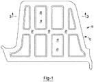
- Fig. 1 shows a baffle structure 10 including a carrier 12.
- the carrier 12 may include a plurality of spaced apart members 22 to form voids 18. From a side profile view as shown in Fig. 2 , the carrier 12 and an expandable material 14 lie in direct planar contact with one another along at least the peripheral rim 16 of the carrier 12.
- the expandable material 14 may include one or more openings (e.g., voids) 20.
- the expandable material 14 may extend only over a portion of the carrier 12.
- the voids 18 formed in the carrier and the voids 20 formed in the expandable may be formed so that they correspond with one another in location, size and shape as shown in Figs. 1 and 3 .
- the baffle of the present invention may be installed into an automotive vehicle although it may be employed for other articles of manufacture such as boats, buildings, furniture, storage containers or the like.
- the baffle may be used to seal and/or baffle a variety of components of an automotive vehicle including, without limitation, body components (e.g., panels), frame components (e.g., hydroformed tubes), pillar structures (e.g., A, B, C or D-pillars), bumpers, roofs, bulkheads, instrument panels, wheel wells, floor pans, door beams, hem flanges, vehicle beltline applications, doors, door sills, rockers, decklids, hoods or the like of the automotive vehicle.
- body components e.g., panels
- frame components e.g., hydroformed tubes
- pillar structures e.g., A, B, C or D-pillars
- bumpers e.g., roofs, bulkheads, instrument panels, wheel wells, floor pans, door beams, hem flanges
- Formation of the materials of the present invention may include a variety of processing steps depending on the desired configuration of the materials.
- the baffle may be formed using a two step molding process in a rotary mold and/or a die cutting process.
- the processing steps may also be free of any die-cutting process.
- One or more of the carrier and the expandable material may be formed in an injection molding process which may be a multi-shot injection molding process. Additional processing and formation steps may not be required. The formation and processing may thus be free of any extrusion process.
- any numerical values recited herein include all values from the lower value to the upper value in increments of one unit provided that there is a separation of at least 2 units between any lower value and any higher value.
- the amount of a component or a value of a process variable such as, for example, temperature, pressure, time and the like is, for example, from 1 to 90, preferably from 20 to 80, more preferably from 30 to 70, it is intended that values such as 15 to 85, 22 to 68, 43 to 51, 30 to 32 etc. are expressly enumerated in this specification. For values which are less than one, one unit is considered to be 0.0001, 0.001, 0.01 or 0.1 as appropriate.
Abstract
A baffle for sealing a vehicle structure, comprising a carrier (12) with an interior body portion characterized by a plurality of spaced-apart members (22), providing voids (20), and an expandable material (14), that may also have openings, disposed on the carrier which, upon expansion, fills a vehicle cavity and covers the interior body portion and each of the voids.
Description
- The present invention relates generally to a baffling and/or sealing member that includes an expandable material and a carrier with voids and spaced-apart members formed of varying materials to reduce weight, material, and cost, and to improve sound attenuation characteristics.
- The transportation industry continues to require methods of baffling and sealing that provide improved sound attenuation and also reduced weight and at a reduced cost. Often, when attempting to reduce the weight of a part providing baffling and/or sealing, the lightweight nature of the support material fails to provide the desired sound attenuation and/or sealing capabilities. Thus, reduced functionality often accompanies lightweight sealing and baffling mechanisms. Traditionally, a baffle including a full coverage open cell foam and a correspondingly shaped carrier to support the foam provide an improved acoustic seal. However, the full coverage nature of such parts make them heavy and more expensive and may be met with assembly issues. It would therefore be desirable to form a carrier and an associated foam that is not a full coverage device and yet provides improved acoustic and sealing capabilities comparable to those of full coverage devices.
- There is thus a need in the art of sealing for low weight sealing and baffling assemblies that provide improved sealing and sound attenuation characteristics and are easily assembled while minimizing weight, material, and cost.
- The present invention meets the aforementioned needs by providing a baffle comprising a carrier having an interior body portion with a plurality of spaced apart members providing voids and a peripheral rim substantially surrounding the interior body portion. The device further includes a thermally expandable sealing material disposed on the carrier in an amount and of a material sufficient for thermally expanding to fill a vehicle cavity and cover the interior body portion and each of the voids.
- The expandable material may be a material that is elastically deformable without rupture for forming a mechanical interconnection with a wall of a cavity of a vehicle. The carrier may be a continuous surface that is substantially free of protuberances. The expandable material may be attached to a face of the carrier. The end of the carrier and end of the expandable material may not be co-extensive. The expandable material may extend laterally to a portion short of a terminating edge of the carrier. The expandable material may extend to a location that is at least 1mm from a terminating edge of the carrier. The baffle may include a fastener formed as a nylon clip integrally formed with the carrier. The baffle may be formed in a two step molding process in a rotary mold. The baffle may be formed by a die-cutting process. The baffle may be formed by processing steps that are free of any die-cutting process. An edge of the carrier may be formed surrounding each void and the expandable material located about the voids is not co-extensive with the edge of the carrier surrounding each void. The expandable material may be co-extensive with the peripheral rim of the carrier. The carrier and expandable material may be formed to each include the same number of voids. The carrier and expandable material may be formed to include differing numbers of voids. The carrier may be formed with at least four voids.
- The teachings herein further contemplate a method for forming the baffles described herein comprising die cutting the carrier to form the voids in the carrier and die cutting the expandable material to form the voids in the expandable material so that the voids in the carrier material and the voids in the expandable material are located in corresponding locations with one another. The method may further include a step of locating the expandable material in direct planar contact with the carrier so that the voids in the expandable material are in an overlying relationship with the voids of the carrier. The method may include a step of locating the baffle within a vehicle cavity. The method may include a step of exposing the expandable material to heat so that the expandable material expands.
- The invention herein contemplates a baffle for the sealing of cavities with a carrier having an interior body portion with a plurality of spaced-apart members providing voids and one or more expandable sealing materials.
-
-
Fig. 1 shows a top down view of an illustrative example of the baffle structure of the present invention. -
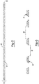
Fig. 2 shows a side profile view of the baffle structure ofFig. 1 . -
Fig. 3 shows a cross-sectional view of the baffle structure ofFig. 1 at line A. - The explanations and illustrations presented herein are intended to acquaint others skilled in the art with the invention, its principles, and its practical application. Those skilled in the art may adapt and apply the invention in its numerous forms, as may be best suited to the requirements of a particular use. Accordingly, the specific embodiments of the present invention as set forth are not intended as being exhaustive or limiting of the teachings. The scope of the teachings should, therefore, be determined not with reference to the above description, but should instead be determined with reference to the appended claims, along with the full scope of equivalents to which such claims are entitled. The disclosures of all articles and references, including patent applications and publications, are incorporated by reference for all purposes. Other combinations are also possible as will be gleaned from the following claims, which are also hereby incorporated by reference into this written description.
- This application is related to and claims the benefit of the priority date of
U.S. Provisional Application Serial No. 61/657,262, filed on June 8, 2012 - The present invention allows for improved baffling and sealing of a cavity using substantially less material than a traditional baffle by providing voids in one or more of the carrier and the expandable material. The baffle disclosed herein may include one or more sealing materials in addition to the carrier and expandable material, which may or may not also include voids. The voids in the expandable material, if present, may be formed so that they correspond in size and location with the voids of the carrier. During expansion, the one or more expandable materials may expand in one or more directions to substantially cover the voids in the carrier.
- The resulting baffle surprisingly provides sufficient sealing comparable to that of baffles including a full coverage carrier while using only a partial coverage carrier. Thus, formation of a baffle in accordance with the present teachings surprisingly includes less carrier materials and expandable materials, but provides a sealing device having full coverage of expandable material, partial coverage of carrier material and yet sufficient sound attenuation and sealing. However, despite existence of the voids in the carrier, the location of the spaced apart members of the carrier must provide sufficient support for the expandable material. As such, the distance between adjacent spaced apart member of the carrier must not be so large that the expandable material either pre or post expansion is likely to sag within the voids.
- The size of the baffle may depend upon the size of the cavity in which the baffle is located. The baffle, comprising the carrier and expandable material by virtue of the voids formed therein, is contemplated to cover no more than 80%, no more than 70%, no more than 60%, or even no more than 50% of a cross section of the cavity, prior to expansion of the expandable material. The voids formed in the baffle, thus, may represent at least 20%, at least 30%, at least 40%, or even at least 50% of the cavity prior to expansion of the expandable material. The thickness of the baffle may be at least about 0.1 mm. The thickness of the baffle may be less than about 10mm. The thickness of the carrier and expandable material may be from about 0.5mm to about 6mm. The thickness of the expandable material may be at least about 0.01mm. The thickness of the expandable material may be less than about 8mm. The thickness of the expandable material may be from about 0.2mm to about 5mm.
- The adjacent spaced apart members of the carrier may be arranged so that the distance between adjacent members is equal. The adjacent spaced apart members of the carrier may be arranged so that the distance between adjacent members is not equal. The spaced apart members may be arranged substantially parallel to one another. The spaced apart members may be arranged substantially perpendicular to one another. The spaced apart members may form a grid configuration. The distance between adjacent spaced apart members may be at least about 0.25mm. The distance between adjacent spaced apart members may be at least about 0.5mm. The distance between adjacent spaced apart members may be at least about 1.0mm. The distance between adjacent spaced apart members may be at least about 3.0mm.
- The size and shape of the voids or openings formed in the carrier material may vary or may be substantially similar. The voids at their largest diameter may be at least about 1mm, at least about 2mm, or even at least about 4mm. The voids are their smallest diameter may be at least about 0.05mm, at least about 0.1mm or even at least about 0.2mm. The voids may be substantially rectangular in shape, substantially triangular in shape, or substantially rounded in shape. The shape, size, and number of the voids may vary depending upon the size of the baffle. For example, a smaller baffle (e.g., a baffle having a largest diameter of 2mm or less) may include three voids or less, whereas a larger baffle (e.g., a baffle having a largest diameter of at least about 10mm), may have 4 voids, 6 voids, 8
voids 10, voids or more. - The carrier may comprise a substantially planar polymeric substrate. The carrier may include a variety of materials such as polymers, elastomers, fibrous materials (e.g., cloth or woven materials), thermoplastics, plastics, nylon, and combinations thereof. The carrier may be injection molded in a multi-shot injection molding process. The carrier may be die-cut. The carrier may also comprise a substantially planar metallic substrate such as steel. The surface of the carrier may be continuous and substantially free of protuberances.
- The expandable material may be attached to a face of the carrier. It is contemplated that the end of the expandable material and the end of the carrier may or may not be co-extensive. The end of the carrier may be any location at which the carrier material does not extend further. Thus the end of the carrier may be an end located adjacent the peripheral edge or an end located adjacent a void. It is thus contemplated that the end of the expandable material and the end of the carrier may be co-extensive at one or more ends of the carrier and may not be co-extensive at one or more ends of the carrier. It is further contemplated that the expandable material may extend laterally to a position short of a terminating edge of the carrier or may extend to a position that is equal to the extension of the terminating edge of the carrier. Again, a terminating edge may be any carrier edge where the carrier material does not extend further. The material may extend to a location that is at least 1mm from a terminating edge of the carrier. The material may extend to a location that is at least 0.5mm from a terminating edge of the carrier. The material may extend to a location that is at least 0.25mm from a terminating edge of the carrier.
- The expandable material may also include one or more openings (e.g., voids), as shown for example in
Figs. 1 and3 , and the voids may be present so as to reduce the amount of material required to effectively seal a cavity, thereby reducing the weight and cost of the baffle. Further, the presence of less than full coverage expandable material may result in more uniform expansion and coverage of the baffle upon expansion of the expandable material. The expandable material may expand to fill the vehicle cavity and cover the interior body portion and each of the voids in the carrier. The baffle may include edges, slots, or attachments that guide the expansion of the expandable sealing material and thus prevent the expandable material from covering the one or more openings. - After placement of the baffle into a cavity, the expandable sealing materials may expand according to a predetermined set of conditions. For example, exposure to certain levels of heat may cause the expandable materials to expand. The volumetric expansion of the expandable materials may vary depending upon the sealing and/or baffling needs of a particular cavity. The expandable material may expand to fill the vehicle cavity and cover the voids in the interior body portion of the carrier. The expandable material may expand at least about 100%. The expandable material may expand less than about 2000%. The expandable material may expand at least about 500%, at least about 1000%, or more. The expandable material may expand less than about 1000% or even less than about 500%.
- The expandable sealing materials may be generally dry to the touch or tacky and may be shaped in any form of desired pattern, placement, or thickness, but is preferably of substantially uniform thickness. Though other heat-activated materials are possible for the expandable sealing materials, a preferred heat activated material is an expandable polymer or plastic, and preferably one that is foamable. The expandable sealing materials may be relatively high expansion foams having a polymeric formulation that includes one or more of an epoxy resin, an acetate (e.g. ethylene vinyl acetate), a thermoplastic polyether, an acrylate and/or a methacrylate (e.g., a copolymer of butyl acrylate and methyl acrylate), an epoxy/elastomer adduct, and one or more fillers (e.g., a clay filler, and/or a nanoparticle-containing filler). Preferred thermally expandable materials are disclosed in
U.S. Patent Nos. 7,313,865 ;7,125,461 ; and7,199,165 incorporated by reference herein for all purposes. For example, and without limitation, the foam may also be an EVA/rubber based material, including an ethylene copolymer or terpolymer that may possess an alpha-olefin. As a copolymer or terpolymer, the polymer is composed of two or three different monomers, i.e., small molecules with high chemical reactivity that are capable of linking up with similar molecules. Suitable expandable materials include those available from L&L Products, Inc. under the designations L7220, L2821, L1066, L205, L2010, L2105, L2108A, L2806, L2811, L4200, L4141, L4161, L4315, L5510, L5520, L5540, L5600, L5601, L7102, and L7104. The expandable materials may be die cut extruded sheets of material. They may be co-injection molded with the carrier in a multi-shot injection molding process. - A number of baffling or sealing foams may also be used for the expandable sealing materials. A typical foam includes a polymeric base material, such as one or more ethylene-based polymers which, when compounded with appropriate ingredients (typically a blowing and curing agent), will expand and cure in a reliable and predictable manner upon the application of heat or the occurrence of a particular condition. From a chemical standpoint for a thermally-activated material, the foam is usually initially processed as a flowable material before curing, and upon curing, the material will typically cross-link making the material incapable of further flow.
- The expandable material can be formed of other materials provided that the material selected is heat-activated or otherwise activated by an ambient condition (e.g. moisture, pressure, time or the like) and cures under appropriate conditions for the selected application. One such material is the epoxy based resin disclosed in
U.S. Patent No. 6,131,897 , the teachings of which are incorporated herein by reference. Some other possible materials include, but are not limited to, polyolefin materials, copolymers and terpolymers with at least one monomer type an alpha-olefin, phenol/formaldehyde materials, phenoxy materials, and polyurethane materials with high glass transition temperatures. Additional materials may also be used such as those disclosed inU.S. Patent Nos. 5,766,719 ;5,755,486 ;5,575,526 ; and5,932,680 , incorporated by reference herein for all purposes. - In applications where the expandable material is a heat activated material, an important consideration involved with the selection and formulation of the material is the temperature at which a material cures and, if expandable, the temperature of expansion. Typically, the material becomes reactive (cures, expands or both) at higher processing temperatures, such as those encountered in an automobile assembly plant, when the material is processed along with the automobile structures at elevated temperatures or at higher applied energy levels, e.g., during coating (e.g., e-coat, paint or clearcoat) curing steps. While temperatures encountered in an automobile assembly operation may be in the range of about 148.89° C to 204.44° C (about 300° F to 400° F) for body shop applications (e.g., e-coat) and, for paint shop applications, are commonly about 93.33° C (about 200° F) or slightly higher (e.g., 120° C-150° C).
- The expandable material may be mechanically attached to the carrier. The expandable sealing material may expand to contact one or more cavity walls to seal the cavity and may be bonded to the carrier over its entire surface or a face of the carrier or may be locally bonded to the carrier at selected locations (e.g., using a tacking type attachment).
- The baffle may include a fastener such as a tree-fastener or a threaded screw fastener. Alternatively, the baffle may be substantially free of any fastener. The fastener may also be provided in a variety of shapes and in a variety of configurations so long as it can secure the sealing device to a cavity. One example of a suitable fastener is disclosed in
U.S. Publication No. 2010/0021267 incorporated by reference herein for all purposes. The fastener may be capable of securing multiple layers or types of materials to a structure. Examples of suitable fasteners include mechanical fasteners, clips, tabs, press-fits, snap-fits, screws, hooks, combinations thereof or the like. Furthermore, it is contemplated that the one or more fasteners may be formed integral of a singular material with the carrier, such as a nylon clip integrally formed with the carrier, or material of the sealing device, or may be formed of a different material and may be removably attached to the carrier. The fastener may be provided as a magnetic material or an adhesive material that can attach (e.g., adhere or magnetically secure) the sealing device to a cavity. In such an embodiment, the magnetic material or the adhesive material may be interspersed within the first sealing material or the second sealing material. Alternatively, the magnetic material or the adhesive material may be disposed upon the first sealing material and/or the second sealing material or may be otherwise connected to the first sealing material, the carrier and/or the second sealing material. - The baffle may include fastening devices for attaching the expandable material to the carrier. Such devices may be integrally formed with the carrier or attached separately. Such devices may include slots, troughs, extension members, or any other shape that may be formed in or attached to the carrier for receiving or connecting to the expandable material.
-
Fig. 1 shows abaffle structure 10 including acarrier 12. Thecarrier 12 may include a plurality of spaced apartmembers 22 to form voids 18. From a side profile view as shown inFig. 2 , thecarrier 12 and anexpandable material 14 lie in direct planar contact with one another along at least theperipheral rim 16 of thecarrier 12. As shown inFigs. 1 and3 , theexpandable material 14 may include one or more openings (e.g., voids) 20. As shown inFig. 3 , theexpandable material 14 may extend only over a portion of thecarrier 12. Thevoids 18 formed in the carrier and thevoids 20 formed in the expandable may be formed so that they correspond with one another in location, size and shape as shown inFigs. 1 and3 . - The baffle of the present invention may be installed into an automotive vehicle although it may be employed for other articles of manufacture such as boats, buildings, furniture, storage containers or the like. The baffle may be used to seal and/or baffle a variety of components of an automotive vehicle including, without limitation, body components (e.g., panels), frame components (e.g., hydroformed tubes), pillar structures (e.g., A, B, C or D-pillars), bumpers, roofs, bulkheads, instrument panels, wheel wells, floor pans, door beams, hem flanges, vehicle beltline applications, doors, door sills, rockers, decklids, hoods or the like of the automotive vehicle.
- Formation of the materials of the present invention may include a variety of processing steps depending on the desired configuration of the materials. The baffle may be formed using a two step molding process in a rotary mold and/or a die cutting process. The processing steps may also be free of any die-cutting process. One or more of the carrier and the expandable material may be formed in an injection molding process which may be a multi-shot injection molding process. Additional processing and formation steps may not be required. The formation and processing may thus be free of any extrusion process.
- Any numerical values recited herein include all values from the lower value to the upper value in increments of one unit provided that there is a separation of at least 2 units between any lower value and any higher value. As an example, if it is stated that the amount of a component or a value of a process variable such as, for example, temperature, pressure, time and the like is, for example, from 1 to 90, preferably from 20 to 80, more preferably from 30 to 70, it is intended that values such as 15 to 85, 22 to 68, 43 to 51, 30 to 32 etc. are expressly enumerated in this specification. For values which are less than one, one unit is considered to be 0.0001, 0.001, 0.01 or 0.1 as appropriate. These are only examples of what is specifically intended and all possible combinations of numerical values between the lowest value and the highest value enumerated are to be considered to be expressly stated in this application in a similar manner. As can be seen, the teaching of amounts expressed as "parts by weight" herein also contemplates the same ranges expressed in terms of percent by weight. Thus, an expression in the Detailed Description of the Invention of a range in terms of at "'x' parts by weight of the resulting polymeric blend composition" also contemplates a teaching of ranges of same recited amount of "x" in percent by weight of the resulting polymeric blend composition."
- Unless otherwise stated, all ranges include both endpoints and all numbers between the endpoints. The use of "about" or "approximately" in connection with a range applies to both ends of the range. Thus, "about 20 to 30" is intended to cover "about 20 to about 30", inclusive of at least the specified endpoints.
- The disclosures of all articles and references, including patent applications and publications, are incorporated by reference for all purposes. The term "consisting essentially of" to describe a combination shall include the elements, ingredients, components or steps identified, and such other elements ingredients, components or steps that do not materially affect the basic and novel characteristics of the combination. The use of the terms "comprising" or "including" to describe combinations of elements, ingredients, components or steps herein also contemplates embodiments that consist essentially of the elements, ingredients, components or steps. By use of the term "may" herein, it is intended that any described attributes that "may" be included are optional.
- Plural elements, ingredients, components or steps can be provided by a single integrated element, ingredient, component or step. Alternatively, a single integrated element, ingredient, component or step might be divided into separate plural elements, ingredients, components or steps. The disclosure of "a" or "one" to describe an element, ingredient, component or step is not intended to foreclose additional elements, ingredients, components or steps.
- It is understood that the above description is intended to be illustrative and not restrictive. Many embodiments as well as many applications besides the examples provided will be apparent to those of skill in the art upon reading the above description. The scope of the invention should, therefore, be determined not with reference to the above description, but should instead be determined with reference to the appended claims, along with the full scope of equivalents to which such claims are entitled. The disclosures of all articles and references, including patent applications and publications, are incorporated by reference for all purposes. The omission in the following claims of any aspect of subject matter that is disclosed herein is not a disclaimer of such subject matter, nor should it be regarded that the inventors did not consider such subject matter to be part of the disclosed inventive subject matter.
Claims (20)
- A baffle comprising:a carrier having a peripheral rim substantially surrounding an interior body portion, the interior body portion being characterized by a plurality of spaced-apart members providing voids;an expandable material disposed on the carrier in an amount and of a material sufficient for thermally expanding to fill a vehicle cavity and cover the interior body portion and each of the voids.
- The baffle of claim 1, wherein the carrier is a continuous surface that is substantially free of protuberances.
- The baffle of claim 1 or claim 2, wherein the expandable material is attached to a face of the carrier.
- The baffle of any of claims 1 through 3, wherein the end of the carrier and end of the expandable material are not co-extensive
- The baffle of any of claims 1 through 4, wherein the expandable material extends laterally to a portion short of a terminating edge of the carrier.
- The baffle of any of claims 1 through 5, wherein the expandable material extends to a location that is at least 1mm from a terminating edge of the carrier.
- The baffle of any of claims 1 through 6, wherein the baffle includes a fastener formed as nylon clip integrally formed with the carrier.
- The baffle of any of claims 1 through 7, wherein the baffle is formed in a two step molding process in a rotary mold.
- The baffle of any of claims 1 through 8, wherein the baffle is formed by a die-cutting process.
- The baffle of any of claims 1 through 7, wherein the baffle is formed by processing steps that are free of any die-cutting process.
- The baffle of any of claims 1 through 10, wherein the carrier includes an integrally formed or separately formed tab, adhesive, post, pow-tab, or any combination thereof for attachment of the expandable material to the carrier.
- The baffle of any of claims 1 through 11, wherein the carrier or the expandable material, or both include an integrally formed or separately formed tab, adhesive, post, pow-tab, or any combination thereof for attachment of the baffle to a wall of the vehicle cavity.
- The baffle of any of claims 1 through 12, wherein an edge of the carrier is formed surrounding each void and the expandable material located about the voids is not co-extensive with the edge of the carrier surrounding each void.
- The baffle of any of claims 1 through 13, wherein the expandable material is co-extensive with the peripheral rim of the carrier.
- The baffle of any of claims 1 through 14, wherein the carrier and expandable material are formed to each include the same number of voids.
- The baffle of any of claims 1 through 15, wherein the carrier and expandable material are formed to include differing numbers of voids.
- The baffle of any of claims 1 through 16 wherein the carrier is formed with at least four voids.
- A method for forming the baffle of any of claims 1 through 17 comprising:die cutting the carrier to form the voids in the carrier;die cutting the expandable material to form the voids in the expandable material so that the voids in the carrier material and the voids in the expandable material are located in corresponding locations with one another;locating the expandable material in direct planar contact with the carrier so that the voids in the expandable material are in an overlying relationship with the voids of the carrier.
- The method of claim 18 including locating the baffle within a vehicle cavity.
- The method of claim 18 or claim 19 including exposing the expandable material to heat so that the expandable material expands.
Applications Claiming Priority (3)
| Application Number | Priority Date | Filing Date | Title |
|---|---|---|---|
| US201261657262P | 2012-06-08 | 2012-06-08 | |
| PCT/US2013/030477 WO2013184194A1 (en) | 2012-06-08 | 2013-03-12 | Baffle with expanding material |
| EP13712981.3A EP2858883B1 (en) | 2012-06-08 | 2013-03-12 | Baffle with expanding material |
Related Parent Applications (1)
| Application Number | Title | Priority Date | Filing Date |
|---|---|---|---|
| EP13712981.3A Division EP2858883B1 (en) | 2012-06-08 | 2013-03-12 | Baffle with expanding material |
Publications (1)
| Publication Number | Publication Date |
|---|---|
| EP3483046A1 true EP3483046A1 (en) | 2019-05-15 |
Family
ID=48014311
Family Applications (2)
| Application Number | Title | Priority Date | Filing Date |
|---|---|---|---|
| EP13712981.3A Active EP2858883B1 (en) | 2012-06-08 | 2013-03-12 | Baffle with expanding material |
| EP18191120.7A Withdrawn EP3483046A1 (en) | 2012-06-08 | 2013-03-12 | Baffle with expanding material |
Family Applications Before (1)
| Application Number | Title | Priority Date | Filing Date |
|---|---|---|---|
| EP13712981.3A Active EP2858883B1 (en) | 2012-06-08 | 2013-03-12 | Baffle with expanding material |
Country Status (6)
| Country | Link |
|---|---|
| US (2) | US9010843B2 (en) |
| EP (2) | EP2858883B1 (en) |
| KR (1) | KR20150021927A (en) |
| CN (1) | CN104349972B (en) |
| BR (1) | BR112014029782B1 (en) |
| WO (1) | WO2013184194A1 (en) |
Families Citing this family (11)
| Publication number | Priority date | Publication date | Assignee | Title |
|---|---|---|---|---|
| EP2159109A1 (en) * | 2008-09-01 | 2010-03-03 | Sika Technology AG | Reinforcement with channel design |
| CA2867929A1 (en) * | 2012-03-20 | 2013-09-26 | Zephyros, Inc. | Baffle assembly |
| JP6235869B2 (en) * | 2013-11-01 | 2017-11-22 | 八千代工業株式会社 | Wave plate fixing structure in fuel tank |
| EP3423270A1 (en) * | 2016-03-02 | 2019-01-09 | Zephyros Inc. | Non-continuous mesh structures |
| US10843641B2 (en) | 2016-04-22 | 2020-11-24 | Sika Technology Ag | Insulating element |
| WO2020028316A1 (en) | 2018-08-02 | 2020-02-06 | Zephyros, Inc. | Baffling member with rivet tab |
| EP3632672A1 (en) * | 2018-10-04 | 2020-04-08 | Zephyros, Inc. | Tailored hybrid blanks |
| US11511610B2 (en) | 2018-11-12 | 2022-11-29 | Shape Corp. | Vehicle door carrier with integrated edge seal and method of manufacture |
| EP3747739A1 (en) * | 2019-06-07 | 2020-12-09 | Zephyros Inc. | Universal high expandable filling member |
| US11827167B2 (en) * | 2020-06-25 | 2023-11-28 | Rivian Ip Holdings, Llc | Wheel deflector for a small overlap crash |
| WO2022040351A2 (en) * | 2020-08-18 | 2022-02-24 | Canoo Technologies Inc. | Manufacturing process for electric vehicle platform |
Citations (20)
| Publication number | Priority date | Publication date | Assignee | Title |
|---|---|---|---|---|
| US5575526A (en) | 1994-05-19 | 1996-11-19 | Novamax Technologies, Inc. | Composite laminate beam for radiator support |
| US5755486A (en) | 1995-05-23 | 1998-05-26 | Novamax Technologies Holdings, Inc. | Composite structural reinforcement member |
| US5766719A (en) | 1994-03-14 | 1998-06-16 | Magna Exterior Systems Gmbh | Composite material |
| JPH10297532A (en) * | 1997-04-24 | 1998-11-10 | Toyota Motor Corp | Assembling structure for closing opening of vehicle body |
| US5932680A (en) | 1993-11-16 | 1999-08-03 | Henkel Kommanditgesellschaft Auf Aktien | Moisture-curing polyurethane hot-melt adhesive |
| JP2000052445A (en) * | 1998-08-06 | 2000-02-22 | Neoex Lab Inc | Hollow chamber shut-off tool in hollow structure |
| US6093358A (en) * | 1998-01-27 | 2000-07-25 | Lear Corporation | Method of making an expandable gap filling product |
| EP1031496A1 (en) * | 1999-02-26 | 2000-08-30 | Möller Plast GmbH | Holder-board with means for fixation in an in-use position |
| JP2000238589A (en) * | 1999-02-22 | 2000-09-05 | Neoex Lab Inc | Hollow space blocking tool for hollow structure |
| US6131897A (en) | 1999-03-16 | 2000-10-17 | L & L Products, Inc. | Structural reinforcements |
| WO2002036338A1 (en) * | 2000-10-31 | 2002-05-10 | Sika Corporation | Expansible synthetic resin baffle with magnetic attachment |
| JP2002302066A (en) * | 2001-04-04 | 2002-10-15 | Neoex Lab Inc | Hollow chamber filler |
| JP2003237624A (en) * | 2002-02-15 | 2003-08-27 | Mitsubishi Motors Corp | Partition of car-body structural member |
| WO2003097405A2 (en) * | 2002-05-17 | 2003-11-27 | L & L Products, Inc. | Improved baffle precursors |
| JP2006224448A (en) * | 2005-02-17 | 2006-08-31 | Honda Motor Co Ltd | Attachment structure of separator member for hollow structure |
| US7125461B2 (en) | 2003-05-07 | 2006-10-24 | L & L Products, Inc. | Activatable material for sealing, baffling or reinforcing and method of forming same |
| US7199165B2 (en) | 2003-06-26 | 2007-04-03 | L & L Products, Inc. | Expandable material |
| US7313865B2 (en) | 2003-01-28 | 2008-01-01 | Zephyros, Inc. | Process of forming a baffling, sealing or reinforcement member with thermoset carrier member |
| US20100021267A1 (en) | 2008-07-24 | 2010-01-28 | Zephyros, Inc. | Push-pin fastening system |
| WO2010060241A1 (en) * | 2008-11-26 | 2010-06-03 | Dow Global Technologies Inc. | Acoustic baffle members and methods for applying acoustic baffles in cavities |
Family Cites Families (110)
| Publication number | Priority date | Publication date | Assignee | Title |
|---|---|---|---|---|
| US625559A (en) | 1899-05-23 | Signal-repeater | ||
| GB903146A (en) | 1959-10-14 | 1962-08-09 | Illinois Tool Works | Improvements relating to fasteners |
| US4751249A (en) | 1985-12-19 | 1988-06-14 | Mpa Diversified Products Inc. | Reinforcement insert for a structural member and method of making and using the same |
| US4901500A (en) | 1987-09-18 | 1990-02-20 | Essex Composite Systems | Lightweight composite beam |
| US4813690A (en) | 1987-11-24 | 1989-03-21 | L & L Products, Inc. | Sealing member |
| DE3838655A1 (en) | 1988-11-15 | 1990-05-17 | Bayerische Motoren Werke Ag | Process and apparatus for filling vehicle body cavities with foam |
| GB8903211D0 (en) | 1989-02-13 | 1989-03-30 | Exxon Chemical Patents Inc | Thermoplastic foamable compositions and car body inserts made from such composition |
| US5266133A (en) | 1993-02-17 | 1993-11-30 | Sika Corporation | Dry expansible sealant and baffle composition and product |
| US5358397A (en) | 1993-05-10 | 1994-10-25 | L&L Products, Inc. | Apparatus for extruding flowable materials |
| ATE228214T1 (en) * | 1993-05-25 | 2002-12-15 | Lord Corp | METHOD OF ACHIEVEING A MECHANICAL BOND BETWEEN SURFACES |
| EP0697956B1 (en) | 1994-03-14 | 1999-06-23 | MAGNA EXTERIOR SYSTEMS GmbH | Composite material with foamable core |
| US5371303A (en) | 1994-03-16 | 1994-12-06 | The Dow Chemical Company | One-step preparation of 4,6-dinitroresorcinol from resorcinol |
| US5708042A (en) | 1994-10-27 | 1998-01-13 | Hasegawa; Itsuro | Method of manufacturing adhesive foamed product |
| US5506025A (en) | 1995-01-09 | 1996-04-09 | Sika Corporation | Expandable baffle apparatus |
| JP2721327B2 (en) * | 1995-02-09 | 1998-03-04 | 株式会社ネオックスラボ | Support structure of foamable material in hollow structure |
| AU6344296A (en) | 1995-07-12 | 1997-02-10 | L & L Products, Inc. | Hollow molded-to-shape expandable sealer |
| JPH09328568A (en) | 1995-12-28 | 1997-12-22 | Otsuka Chem Co Ltd | Expandable composition |
| US6341467B1 (en) * | 1996-05-10 | 2002-01-29 | Henkel Corporation | Internal reinforcement for hollow structural elements |
| US6270600B1 (en) | 1996-07-03 | 2001-08-07 | Henkel Corporation | Reinforced channel-shaped structural member methods |
| DE19632550A1 (en) | 1996-08-13 | 1998-02-19 | Moeller Plast Gmbh | Wall or building element and process for its manufacture |
| DE19648164C2 (en) | 1996-11-21 | 2000-01-27 | Karmann Gmbh W | Body part, in particular profile frame support |
| US5931474A (en) | 1997-02-24 | 1999-08-03 | Raychem Corporation | Cavity sealing article and method |
| JP2001513713A (en) | 1997-02-24 | 2001-09-04 | レイケム・コーポレイション | Hollow sealing material and sealing method |
| US5766179A (en) | 1997-03-05 | 1998-06-16 | Orthofix S.R.L. | Mechanical system for blind nail-hole alignment of bone screws |
| US6099948A (en) | 1997-05-08 | 2000-08-08 | Henkel Corporation | Encapsulation of pre-expanded elastomeric foam with a thermoplastic |
| US6233826B1 (en) | 1997-07-21 | 2001-05-22 | Henkel Corp | Method for reinforcing structural members |
| US6096403A (en) | 1997-07-21 | 2000-08-01 | Henkel Corporation | Reinforced structural members |
| US5830395A (en) | 1997-08-12 | 1998-11-03 | E. I. Du Pont De Nemours And Company | Process for making a uniform dispersion of aramid fibers and polymer |
| US6451231B1 (en) | 1997-08-21 | 2002-09-17 | Henkel Corporation | Method of forming a high performance structural foam for stiffening parts |
| DE19753318A1 (en) | 1997-12-02 | 1999-06-10 | Sika Ag | Reinforcing element for load-bearing or load-transmitting components and method for fastening it to a component surface |
| JP4229344B2 (en) | 1997-12-03 | 2009-02-25 | 日本テクニカ株式会社 | Structure of the body cylindrical cavity filling the foam filling member |
| DE19812288C1 (en) | 1998-03-20 | 1999-05-27 | Moeller Plast Gmbh | Hollow profile for motor vehicle bodywork |
| DE19856255C1 (en) | 1998-03-20 | 2000-01-20 | Moeller Plast Gmbh | Hollow profile with internal reinforcement |
| DE19835704B4 (en) | 1998-08-07 | 2004-05-27 | Bayerische Motoren Werke Ag | vehicle body |
| US6387470B1 (en) | 1998-11-05 | 2002-05-14 | Sika Corporation | Sound deadening and structural reinforcement compositions and methods of using the same |
| DE29904705U1 (en) | 1998-12-23 | 1999-06-17 | Mannesmann Ag | Device for producing a profile part |
| US6276105B1 (en) | 1999-01-11 | 2001-08-21 | Henkel Corporation | Laminate reinforced beam with tapered polymer layer |
| US6189953B1 (en) | 1999-01-25 | 2001-02-20 | Henkel Corporation | Reinforced structural assembly |
| WO2001019667A1 (en) | 1999-02-11 | 2001-03-22 | Tyco Electronics Corporation | Article for sealing a cavity whose cross-section includes an acute corner and method of using the same |
| US6150428A (en) | 1999-09-28 | 2000-11-21 | Sika Corporation | Expansion temperature tolerant dry expandable sealant and baffle product and method of preparing same |
| US6758738B1 (en) * | 1999-09-30 | 2004-07-06 | Noble Polymers, Llc | Damper with integral seal |
| WO2001054936A1 (en) | 2000-01-31 | 2001-08-02 | Sika Corporation | Structural reinforcing member with ribbed thermally expansible foaming material |
| US6199940B1 (en) | 2000-01-31 | 2001-03-13 | Sika Corporation | Tubular structural reinforcing member with thermally expansible foaming material |
| US6305136B1 (en) | 2000-01-31 | 2001-10-23 | Sika Corporation | Reinforcing member with beam shaped carrier and thermally expansible reinforcing material |
| US6422575B1 (en) | 2000-03-14 | 2002-07-23 | L&L Products, Inc. | Expandable pre-formed plug |
| US6296298B1 (en) | 2000-03-14 | 2001-10-02 | L&L Products, Inc. | Structural reinforcement member for wheel well |
| JP2002012167A (en) | 2000-04-26 | 2002-01-15 | Neoex Lab Inc | Reinforcing structure of hollow structure and reinforcing tool therefor |
| US6413611B1 (en) | 2000-05-01 | 2002-07-02 | Sika Corporation | Baffle and reinforcement assembly |
| WO2001088033A1 (en) | 2000-05-16 | 2001-11-22 | Sika Corporation | Sound deadening and structural reinforcement compositions and methods of using the same |
| US6820923B1 (en) | 2000-08-03 | 2004-11-23 | L&L Products | Sound absorption system for automotive vehicles |
| US6620501B1 (en) | 2000-08-07 | 2003-09-16 | L&L Products, Inc. | Paintable seal system |
| JP2002221968A (en) | 2001-01-25 | 2002-08-09 | Neoex Lab Inc | Hollow chamber shut-off means |
| US6546693B2 (en) | 2001-04-11 | 2003-04-15 | Henkel Corporation | Reinforced structural assembly |
| US6787579B2 (en) | 2001-05-02 | 2004-09-07 | L&L Products, Inc. | Two-component (epoxy/amine) structural foam-in-place material |
| JP2002331960A (en) | 2001-05-08 | 2002-11-19 | Neoex Lab Inc | Hollow part blocking tool for hollow structure |
| JP3694253B2 (en) | 2001-05-22 | 2005-09-14 | 林シーカ・オートモーティブ株式会社 | Automotive cavity sealant |
| JP2002347058A (en) | 2001-05-29 | 2002-12-04 | Neoex Lab Inc | Filling implement of hollow panel |
| US7169467B2 (en) | 2001-06-21 | 2007-01-30 | Magna International Of America, Inc. | Structural foam composite having nano-particle reinforcement and method of making the same |
| US7017969B1 (en) * | 2001-08-01 | 2006-03-28 | Kevin Kirkham | Interior shield on the lid of the trunk of a vehicle to prevent the lid of the trunk from being damaged by the contents contained beneath the lid |
| US6706802B2 (en) | 2001-08-31 | 2004-03-16 | L & L Products, Inc. | Sealants |
| US6786533B2 (en) | 2001-09-24 | 2004-09-07 | L&L Products, Inc. | Structural reinforcement system having modular segmented characteristics |
| US6846559B2 (en) | 2002-04-01 | 2005-01-25 | L&L Products, Inc. | Activatable material |
| WO2003089221A1 (en) | 2002-04-15 | 2003-10-30 | Dow Global Technologies Inc. | Improved vehicular structural members and method of making the members |
| US7077460B2 (en) | 2002-04-30 | 2006-07-18 | L&L Products, Inc. | Reinforcement system utilizing a hollow carrier |
| US20040011282A1 (en) | 2002-07-18 | 2004-01-22 | Myers Robert D. | System and method for manufacturing physical barriers |
| US6920693B2 (en) | 2002-07-24 | 2005-07-26 | L&L Products, Inc. | Dynamic self-adjusting assembly for sealing, baffling or structural reinforcement |
| US6811864B2 (en) | 2002-08-13 | 2004-11-02 | L&L Products, Inc. | Tacky base material with powder thereon |
| US20040076831A1 (en) | 2002-10-02 | 2004-04-22 | L&L Products, Inc. | Synthetic material and methods of forming and applying same |
| GB0300159D0 (en) | 2003-01-06 | 2003-02-05 | L & L Products Inc | Improved reinforcing members |
| JP4006344B2 (en) | 2003-01-31 | 2007-11-14 | 林シーカ・オートモーティブ株式会社 | Arrangement structure of foamable filler and engagement structure of the foamable filler |
| US20050172486A1 (en) | 2004-02-05 | 2005-08-11 | L&L Products, Inc. | Member for sealing, baffling or reinforcing and method of forming same |
| EP1591224A1 (en) | 2004-04-27 | 2005-11-02 | Sika Technology AG | Device and method for sound damping device in cavities of vehicles |
| US20050260399A1 (en) | 2004-05-19 | 2005-11-24 | L&L Products, Inc. | Synthetic material having selective expansion characteristics |
| EP1598393A1 (en) | 2004-05-19 | 2005-11-23 | Sika Technology AG | Filler based on polymer coated particles, for filling of cavities, particularly of structural elements, preparation thereof and structural element |
| US7838589B2 (en) | 2004-07-21 | 2010-11-23 | Zephyros, Inc. | Sealant material |
| US7521093B2 (en) | 2004-07-21 | 2009-04-21 | Zephyros, Inc. | Method of sealing an interface |
| JP4451273B2 (en) | 2004-10-28 | 2010-04-14 | イイダ産業株式会社 | Foam filler |
| US8087916B2 (en) | 2005-12-15 | 2012-01-03 | Cemedine Henkel Co., Ltd. | Holding jig for a foamable material |
| US7913467B2 (en) * | 2006-07-25 | 2011-03-29 | Zephyros, Inc. | Structural reinforcements |
| US7841647B2 (en) | 2006-11-15 | 2010-11-30 | Sika Technology Ag | Baffle assembly |
| DE102007038659A1 (en) | 2007-08-15 | 2009-02-19 | Henkel Ag & Co. Kgaa | Expandable filler insert for filling hollow spaces, comprises self-supporting continuous structure including polymer matrix containing polymer(s) or polymer precursor and latent blowing agent(s), and spacer and/or fixing element |
| EP1932648A1 (en) | 2006-12-15 | 2008-06-18 | Sika Technology AG | Structural reinforcement material, insert, and reinforced cavity comprising same |
| EP1935955A1 (en) | 2006-12-21 | 2008-06-25 | Sika Technology AG | Method for adhesively bonding a hem flange |
| EP2109563A1 (en) * | 2006-12-28 | 2009-10-21 | Henkel Kommanditgesellschaft auf Aktien | Acoustic baffle |
| DE102007015394A1 (en) | 2007-03-28 | 2008-10-02 | Henkel Ag & Co. Kgaa | Soundproof partition for sealing a cavity |
| US20090001758A1 (en) | 2007-06-29 | 2009-01-01 | Sika Technology Ag | Expandable insert for hollow structure |
| PL2176113T3 (en) | 2007-08-16 | 2011-09-30 | Henkel Ag & Co Kgaa | Acoustic baffle |
| GB0720301D0 (en) | 2007-10-17 | 2007-11-28 | Zephyros Inc | Multi functional vehicle components |
| US8998688B2 (en) | 2007-10-24 | 2015-04-07 | Sika Technology Ag | Exhauster baffle |
| WO2009091953A2 (en) | 2008-01-16 | 2009-07-23 | Sika Technology Ag | Extruded expandable barrier |
| US8293360B2 (en) | 2008-02-27 | 2012-10-23 | Sika Technology Ag | Baffle |
| BRPI0909810A2 (en) | 2008-03-17 | 2015-10-06 | Zephyros Inc | insert with integrated fastener |
| WO2009124177A1 (en) | 2008-04-04 | 2009-10-08 | Sika Technology Ag | Expandable barrier |
| FR2930509B1 (en) | 2008-04-29 | 2010-04-16 | Peugeot Citroen Automobiles Sa | AUTOMOTIVE VEHICLE STRUCTURE, MANUFACTURING METHOD THEREFOR, AND VEHICLE COMPRISING SUCH A STRUCTURE |
| EP2147848B1 (en) | 2008-07-25 | 2016-03-30 | Sika Technology AG | Interconnected foam or adhesive layers |
| WO2010014565A1 (en) * | 2008-07-29 | 2010-02-04 | Dow Global Technologies Inc. | Toughened expandable epoxy resins for stiffening and energy dissipation in automotive cavities |
| EP2154051B1 (en) | 2008-08-05 | 2011-11-30 | Sika Technology AG | Baffle |
| BRPI0823303A2 (en) | 2008-12-16 | 2015-06-23 | Henkel Ag & Co Kgaa | Muffler plate with improved acoustic damping properties |
| JP2010168036A (en) | 2008-12-26 | 2010-08-05 | Nitto Denko Corp | Shield plate and vehicle structure provided with the shield plate |
| JP5460740B2 (en) * | 2009-02-27 | 2014-04-02 | シーカ・テクノロジー・アーゲー | Structural reinforcement system |
| ATE522401T1 (en) | 2009-04-03 | 2011-09-15 | Sika Technology Ag | ELEMENT FOR SEALING OR REINFORCING A CAVITY AND METHOD FOR INSERTING A PENETRATING ELEMENT IN SUCH AN ELEMENT |
| US7984919B2 (en) * | 2009-05-18 | 2011-07-26 | Zephyros, Inc. | Structural mounting insert having a non-conductive isolator |
| US8390906B2 (en) | 2009-09-11 | 2013-03-05 | Palo Alto Research Center Incorporated | Membrane-based methods and system for color characterization |
| EP2330019A1 (en) | 2009-12-04 | 2011-06-08 | Sika Technology AG | Baffle reverse molding |
| EP2360002A1 (en) | 2010-02-11 | 2011-08-24 | Sika Technology AG | Baffle or reinforcer with fixation mechanism |
| US8545956B2 (en) | 2010-04-26 | 2013-10-01 | Sika Technology Ag | Expandable insert with flexible substrate |
| EP2390077A1 (en) | 2010-05-25 | 2011-11-30 | Sika Technology AG | Overmolding extruded profiles |
| WO2011150142A2 (en) | 2010-05-28 | 2011-12-01 | Henkel Ag & Co. Kgaa | Acoustic baffle device |
| WO2012078729A1 (en) | 2010-12-08 | 2012-06-14 | Zephyros, Inc. | Sealing assembly |
| US8444214B2 (en) | 2011-09-06 | 2013-05-21 | Sika Technology Ag | Baffle with self-closing flap assembly |
-
2013
- 2013-03-12 KR KR1020147033769A patent/KR20150021927A/en active IP Right Grant
- 2013-03-12 EP EP13712981.3A patent/EP2858883B1/en active Active
- 2013-03-12 CN CN201380030189.2A patent/CN104349972B/en active Active
- 2013-03-12 EP EP18191120.7A patent/EP3483046A1/en not_active Withdrawn
- 2013-03-12 US US13/796,399 patent/US9010843B2/en active Active
- 2013-03-12 BR BR112014029782-7A patent/BR112014029782B1/en active IP Right Grant
- 2013-03-12 WO PCT/US2013/030477 patent/WO2013184194A1/en active Application Filing
-
2015
- 2015-03-24 US US14/666,821 patent/US9776368B2/en active Active
Patent Citations (20)
| Publication number | Priority date | Publication date | Assignee | Title |
|---|---|---|---|---|
| US5932680A (en) | 1993-11-16 | 1999-08-03 | Henkel Kommanditgesellschaft Auf Aktien | Moisture-curing polyurethane hot-melt adhesive |
| US5766719A (en) | 1994-03-14 | 1998-06-16 | Magna Exterior Systems Gmbh | Composite material |
| US5575526A (en) | 1994-05-19 | 1996-11-19 | Novamax Technologies, Inc. | Composite laminate beam for radiator support |
| US5755486A (en) | 1995-05-23 | 1998-05-26 | Novamax Technologies Holdings, Inc. | Composite structural reinforcement member |
| JPH10297532A (en) * | 1997-04-24 | 1998-11-10 | Toyota Motor Corp | Assembling structure for closing opening of vehicle body |
| US6093358A (en) * | 1998-01-27 | 2000-07-25 | Lear Corporation | Method of making an expandable gap filling product |
| JP2000052445A (en) * | 1998-08-06 | 2000-02-22 | Neoex Lab Inc | Hollow chamber shut-off tool in hollow structure |
| JP2000238589A (en) * | 1999-02-22 | 2000-09-05 | Neoex Lab Inc | Hollow space blocking tool for hollow structure |
| EP1031496A1 (en) * | 1999-02-26 | 2000-08-30 | Möller Plast GmbH | Holder-board with means for fixation in an in-use position |
| US6131897A (en) | 1999-03-16 | 2000-10-17 | L & L Products, Inc. | Structural reinforcements |
| WO2002036338A1 (en) * | 2000-10-31 | 2002-05-10 | Sika Corporation | Expansible synthetic resin baffle with magnetic attachment |
| JP2002302066A (en) * | 2001-04-04 | 2002-10-15 | Neoex Lab Inc | Hollow chamber filler |
| JP2003237624A (en) * | 2002-02-15 | 2003-08-27 | Mitsubishi Motors Corp | Partition of car-body structural member |
| WO2003097405A2 (en) * | 2002-05-17 | 2003-11-27 | L & L Products, Inc. | Improved baffle precursors |
| US7313865B2 (en) | 2003-01-28 | 2008-01-01 | Zephyros, Inc. | Process of forming a baffling, sealing or reinforcement member with thermoset carrier member |
| US7125461B2 (en) | 2003-05-07 | 2006-10-24 | L & L Products, Inc. | Activatable material for sealing, baffling or reinforcing and method of forming same |
| US7199165B2 (en) | 2003-06-26 | 2007-04-03 | L & L Products, Inc. | Expandable material |
| JP2006224448A (en) * | 2005-02-17 | 2006-08-31 | Honda Motor Co Ltd | Attachment structure of separator member for hollow structure |
| US20100021267A1 (en) | 2008-07-24 | 2010-01-28 | Zephyros, Inc. | Push-pin fastening system |
| WO2010060241A1 (en) * | 2008-11-26 | 2010-06-03 | Dow Global Technologies Inc. | Acoustic baffle members and methods for applying acoustic baffles in cavities |
Also Published As
| Publication number | Publication date |
|---|---|
| US9776368B2 (en) | 2017-10-03 |
| BR112014029782B1 (en) | 2022-03-29 |
| KR20150021927A (en) | 2015-03-03 |
| CN104349972A (en) | 2015-02-11 |
| US20130328349A1 (en) | 2013-12-12 |
| BR112014029782A2 (en) | 2017-06-27 |
| WO2013184194A1 (en) | 2013-12-12 |
| BR112014029782A8 (en) | 2021-08-31 |
| EP2858883B1 (en) | 2018-08-29 |
| US20150190977A1 (en) | 2015-07-09 |
| CN104349972B (en) | 2018-02-02 |
| US9010843B2 (en) | 2015-04-21 |
| EP2858883A1 (en) | 2015-04-15 |
Similar Documents
| Publication | Publication Date | Title |
|---|---|---|
| EP2858883B1 (en) | Baffle with expanding material | |
| US10703067B2 (en) | Structural adhesive assemblies | |
| US9713885B2 (en) | Sealing assembly | |
| US8967327B2 (en) | Baffle assembly | |
| US8801079B2 (en) | Load actuated baffle | |
| US8926780B2 (en) | Cavity sealing assembly | |
| EP2265484A1 (en) | Insert with integrated fastener | |
| US8918983B2 (en) | Integrated fastening system | |
| US8790058B2 (en) | Push-pin cavity sealer | |
| US11654976B2 (en) | Anti-flutter baffle | |
| US20160046327A1 (en) | Anti-deformation spring baffle | |
| US20170114899A1 (en) | Elastic Integrated Molded Baffler and Sealer | |
| US20170050412A1 (en) | Reinforcement and Sealing System |
Legal Events
| Date | Code | Title | Description |
|---|---|---|---|
| PUAI | Public reference made under article 153(3) epc to a published international application that has entered the european phase |
Free format text: ORIGINAL CODE: 0009012 |
|
| AC | Divisional application: reference to earlier application |
Ref document number: 2858883 Country of ref document: EP Kind code of ref document: P |
|
| AK | Designated contracting states |
Kind code of ref document: A1 Designated state(s): AL AT BE BG CH CY CZ DE DK EE ES FI FR GB GR HR HU IE IS IT LI LT LU LV MC MK MT NL NO PL PT RO RS SE SI SK SM TR |
|
| STAA | Information on the status of an ep patent application or granted ep patent |
Free format text: STATUS: THE APPLICATION IS DEEMED TO BE WITHDRAWN |
|
| 18D | Application deemed to be withdrawn |
Effective date: 20191116 |