JP5233455B2 - Transfer fixing device and image forming apparatus - Google Patents
Transfer fixing device and image forming apparatus Download PDFInfo
- Publication number
- JP5233455B2 JP5233455B2 JP2008179239A JP2008179239A JP5233455B2 JP 5233455 B2 JP5233455 B2 JP 5233455B2 JP 2008179239 A JP2008179239 A JP 2008179239A JP 2008179239 A JP2008179239 A JP 2008179239A JP 5233455 B2 JP5233455 B2 JP 5233455B2
- Authority
- JP
- Japan
- Prior art keywords
- transfer
- heat
- paper
- fixing device
- recording medium
- Prior art date
- Legal status (The legal status is an assumption and is not a legal conclusion. Google has not performed a legal analysis and makes no representation as to the accuracy of the status listed.)
- Expired - Fee Related
Links
Images


Classifications
-
- G—PHYSICS
- G03—PHOTOGRAPHY; CINEMATOGRAPHY; ANALOGOUS TECHNIQUES USING WAVES OTHER THAN OPTICAL WAVES; ELECTROGRAPHY; HOLOGRAPHY
- G03G—ELECTROGRAPHY; ELECTROPHOTOGRAPHY; MAGNETOGRAPHY
- G03G15/00—Apparatus for electrographic processes using a charge pattern
- G03G15/22—Apparatus for electrographic processes using a charge pattern involving the combination of more than one step according to groups G03G13/02 - G03G13/20
-
- G—PHYSICS
- G03—PHOTOGRAPHY; CINEMATOGRAPHY; ANALOGOUS TECHNIQUES USING WAVES OTHER THAN OPTICAL WAVES; ELECTROGRAPHY; HOLOGRAPHY
- G03G—ELECTROGRAPHY; ELECTROPHOTOGRAPHY; MAGNETOGRAPHY
- G03G2215/00—Apparatus for electrophotographic processes
- G03G2215/16—Transferring device, details
- G03G2215/1676—Simultaneous toner image transfer and fixing
- G03G2215/1695—Simultaneous toner image transfer and fixing at the second or higher order transfer point
Description
本発明は、電子写真、静電記録、静電印刷に用いられる転写定着装置、及び該転写定着装置を備える画像形成装置に関するものである。 The present invention relates to a transfer fixing device used for electrophotography, electrostatic recording, electrostatic printing, and an image forming apparatus including the transfer fixing device.
従来、像担持体(感光体)上に、現像手段により画像を形成し、その画像を1次転写手段により中間転写体へ転写し、さらに中間転写体上の画像を2次転写手段により転写材に転写し、かかる転写材上の画像を定着手段により定着するようになされている構成の画像形成装置が広く知られている。
また、上記各工程を段階的に行う構成の画像形成装置も汎用されているが、その他として、転写工程と定着工程を同時に行うことを可能とした、いわゆる転写定着工程を行うようになされている画像形成装置についても提案がなされている(例えば、特許文献1及び2参照)。特許文献1には、中間転写体から転写材に2次転写定着を行う構成の画像形成装置が示されており、特許文献2には、中間転写体から転写定着体に2次転写定着した後、転写定着体から転写材に3次転写定着する構成の画像形成装置が示されている。
Conventionally, an image is formed on an image carrier (photoreceptor) by a developing unit, the image is transferred to an intermediate transfer member by a primary transfer unit, and an image on the intermediate transfer member is transferred by a secondary transfer unit. 2. Description of the Related Art Image forming apparatuses having a configuration in which an image on a transfer material is fixed to an image on a transfer material by a fixing unit are widely known.
In addition, an image forming apparatus configured to perform the above steps step by step is also widely used. In addition, a so-called transfer fixing step that enables the transfer step and the fixing step to be performed simultaneously is performed. An image forming apparatus has also been proposed (see, for example, Patent Documents 1 and 2). Patent Document 1 shows an image forming apparatus configured to perform secondary transfer fixing from an intermediate transfer member to a transfer material.
画像形成技術においては、トナー(樹脂を主体とした帯電性の粉体)が一般的に利用されている。かかる画像形成において、画像品質の低下を招来しやすい工程は、転写工程である。
画像を形成する記録媒体としては、主に紙が用いられているが、普通紙から厚紙までさまざまな厚さのものがある。また表面性についても上質なものから粗いものまでさまざまである。特に、表面性の粗い紙を適用すると、紙の表面性に追従できずに微小ギャップが形成されてしまい、かかる微小ギャップ部分で異常放電が発生し、画像が正常に転写されずに、全体としてぼそついた画像になりやすいという不具合が生じる。
In image forming technology, toner (chargeable powder mainly composed of resin) is generally used. In such image formation, a process that tends to cause a decrease in image quality is a transfer process.
As a recording medium for forming an image, paper is mainly used, but there are various thicknesses from plain paper to cardboard. Also, the surface properties vary from fine to rough. In particular, when paper with rough surface properties is applied, a minute gap is formed without following the surface property of the paper, abnormal discharge occurs in the minute gap portion, and the image is not transferred normally, There is a problem that the image tends to be blurred.
これに対し、転写工程と定着工程とが同時に行われる機能を具備する画像形成装置においては、表面性の粗い記録媒体(紙)を使用した場合においても画像品質の低下しにくくなるという利点を備えている。これは、転写工程において、加圧と同時に加熱を行うため、トナーが軟化・溶融して粘弾性を帯びたブロック状の塊となり、紙の表面の微小ギャップ部分に相当する位置においても、転写できるようになるためである。
上述したことから、転写定着手段を具備する画像形成装置は、高画質達成に最適な手段を適用した構成を有していると言えるものである。
On the other hand, an image forming apparatus having a function in which a transfer process and a fixing process are performed at the same time has an advantage that image quality is hardly deteriorated even when a recording medium (paper) having a rough surface is used. ing. This is because in the transfer process, heating is performed simultaneously with pressurization, so that the toner is softened and melted into a block-like lump having viscoelasticity, and can be transferred even at a position corresponding to a minute gap portion on the surface of the paper. This is because
From the above, it can be said that the image forming apparatus including the transfer fixing unit has a configuration to which a unit optimal for achieving high image quality is applied.
更に、転写定着方式においては、記録媒体に粉体が乗った状態で走行するようなことがないため、転写定着部の直前まで通紙方向を狭く限定した構成の搬送ガイドを設置することができ、薄紙から厚紙まで、その他の紙種等、種々の条件に対応した搬送を行うことができるという利点がある。このように紙種対応の自由度が高いと、通紙詰まりの発生率を効果的に低減化することも可能となる。
通常の電子写真では、転写定着部の直前まで記録媒体に粉体が乗っているため、搬送ガイドはこの粉体を擦ることがないように隙間を設けてしか案内できないため、この隙間の中で記録媒体が不安定になり通紙詰まりが発生することが多い。
Furthermore, in the transfer fixing method, since the recording medium does not travel with powder on it, a conveyance guide having a configuration in which the sheet passing direction is narrowly limited to just before the transfer fixing unit can be installed. Further, there is an advantage that it is possible to perform conveyance corresponding to various conditions such as other paper types from thin paper to thick paper. As described above, when the degree of freedom corresponding to the paper type is high, it is possible to effectively reduce the occurrence rate of the paper jam.
In normal electrophotography, since the powder is on the recording medium until just before the transfer fixing unit, the conveyance guide can only guide with a gap so as not to rub this powder. In many cases, the recording medium becomes unstable and paper jam occurs.
ところで、転写定着工程における熱効率を充分に高くするためには、記録媒体(紙)とトナーを融着する面、すなわち紙とトナーの界面の温度を高めることが必要である。
従来においては、トナーを十分に加熱し軟化した状態として紙に圧接させる方式を適用してきた。しかしながら、この方式において充分な効果を得るためには、トナーを加熱するのみならず転写定着部材も加熱することを行っていたため、転写定着部材が例えば300μmと厚い場合、特に、4連タンデム作像方式等を採用し、周長が長い場合においては、充分な熱効率が確保できない場合があった。また更には、後工程において冷却しなければならず、その結果、同一部材を一方で加熱し、一方で冷却する構成としなければならないので、エネルギー効率の観点からは非常に不利な構成であった。
By the way, in order to sufficiently increase the thermal efficiency in the transfer and fixing process, it is necessary to increase the temperature at which the recording medium (paper) and the toner are fused, that is, the interface between the paper and the toner.
Conventionally, a method in which toner is sufficiently heated and softened and pressed against paper has been applied. However, in order to obtain a sufficient effect in this system, not only the toner but also the transfer fixing member is heated. Therefore, when the transfer fixing member is as thick as 300 μm, for example, quadruple tandem imaging is performed. When a method or the like is employed and the circumference is long, sufficient thermal efficiency may not be ensured. Furthermore, since the same member must be cooled on the one hand and cooled on the other hand in the subsequent process, it is a very disadvantageous structure from the viewpoint of energy efficiency. .
上述したような課題に鑑みて、記録媒体(紙)そのものを選択的に、トナーが接触する直前において加熱するという技術についての提案もなされた(例えば、許文献3参照)。しかしながら、この方式においては、温度ムラが発生してしまうという課題が残っており、特に、多数枚印刷において、いわゆる地汚れが付着しやすくなるという欠点もあった。
また、従来の転写定着で行われているように、記録媒体を定着に寄与しない裏面まで加熱することはエネルギーの無駄になるため、転写直前に記録媒体の転写面のみ温度上昇させ、かつ温度低下を防止できることが好ましいが、そのような技術は未だ提案されていない。
In view of the problems as described above, there has also been proposed a technique for selectively heating the recording medium (paper) itself immediately before the toner contacts (see, for example, Permissible Document 3). However, this method still has a problem that temperature unevenness occurs, and in particular, there is a drawback that so-called scumming tends to adhere in printing a large number of sheets.
Also, as is done with conventional transfer and fixing, heating the recording medium to the back side that does not contribute to fixing wastes energy, so the temperature of the recording medium is increased immediately before the transfer, and the temperature is decreased. However, such a technique has not been proposed yet.
転写直前に記録媒体の転写面のみ温度上昇させる方法として、板状の加熱部材、又は高温の回転部材を設けて、搬送される記録媒体(以下、「用紙」ということがある)を加熱する手段が考えられる。しかしながら、いずれの方式においても、用紙が加熱部材との接触を離れて、トナー像が転写されるニップに到達するまでの間に用紙表面温度が低下するという問題があり、特に、用紙が厚くなると温度低下は顕著になるという問題がある。 As a method for raising the temperature of only the transfer surface of the recording medium immediately before the transfer, a plate-like heating member or a high-temperature rotating member is provided to heat the recording medium to be conveyed (hereinafter sometimes referred to as “paper”). Can be considered. However, in any of the methods, there is a problem that the surface temperature of the paper decreases until the paper leaves the contact with the heating member and reaches the nip where the toner image is transferred. There is a problem that the temperature drop becomes remarkable.
ここで、陰解法を用いた1次元伝熱解析シミュレーション結果の一例を示す。図5及び図6に示すように160℃の高熱アルミローラと25℃の発砲シリコンローラ(共に表層はテフロン(登録商標))間に、ニップ幅20msecで用紙を通した時の用紙表面温度上昇の様子を図7及び図8にそれぞれ示す。
図7に示すグラフが薄紙(50k紙)を通紙した場合、図8に示すグラフが厚紙(300g)紙を通紙した場合である。それぞれのグラフ中の「空走」は、図5に示すように雰囲気温度40℃の空中に搬送した場合、「加熱」は、図6に示すように熱流束44000W/m2の輻射ハロゲンヒータ下を搬送した場合である。
転写定着においてトナーを加熱溶融させる際に必要となる温度は、紙表面温度(図7及び8中の「紙:上面」)で示される。ニップ幅20msecの区間で約140℃まで加熱された用紙表面は、雰囲気温度40℃の空中に搬送した場合、30msec程度の搬送時間で約70℃まで温度低下しているのが分かる。厚紙300g紙の場合、上面の熱が低温度の紙中央方向に熱伝達する為、薄紙50k紙の場合よりも温度低下が大きい。いずれの場合でも、上記30msecは搬送速度200mm/secの中速領域でも搬送距離は僅か6mmであって、用紙が加熱部を抜けてから転写定着領域に到達するまでの距離をできるだけ短くしないと熱効率が著しく低下するのが分かる。
一方、加熱部を抜けてから用紙をヒータで輻射加熱する場合、用紙表面の温度低下が30〜40℃程度に抑えられ、加熱部から転写定着領域に到達するまでの距離を長くしても転写定着領域で充分な用紙表面温度を確保することが可能となることがわかる。
Here, an example of the one-dimensional heat transfer analysis simulation result using the implicit method is shown. As shown in FIG. 5 and FIG. 6, the paper surface temperature rises when the paper is passed with a nip width of 20 msec between a high-temperature aluminum roller of 160 ° C. and a silicon roller of 25 ° C. (both surface layers are Teflon (registered trademark)). The situation is shown in FIGS. 7 and 8, respectively.
The graph shown in FIG. 7 is a case where a thin paper (50k paper) is passed, and the graph shown in FIG. 8 is a case where a thick paper (300 g) paper is passed. As shown in FIG. 5, “idle running” in each graph is when the air is transported in the air at an atmospheric temperature of 40 ° C., and “heating” is below the radiant halogen heater having a heat flux of 44000 W / m 2 as shown in FIG. 6. Is transported.
The temperature required to heat and melt the toner in the transfer and fixing is indicated by the paper surface temperature (“paper: upper surface” in FIGS. 7 and 8). It can be seen that the surface of the paper heated to about 140 ° C. in the section having a nip width of 20 msec is lowered to about 70 ° C. in a conveyance time of about 30 msec when conveyed in the air at an atmospheric temperature of 40 ° C. In the case of 300 g thick paper, the heat on the upper surface is transferred toward the center of the low temperature paper, so the temperature drop is larger than in the case of thin 50 k paper. In either case, the above 30 msec is only 6 mm even in the medium speed region where the conveyance speed is 200 mm / sec, and it is necessary to minimize the distance from the time when the paper passes through the heating unit until it reaches the transfer fixing region. It can be seen that is significantly reduced.
On the other hand, when the paper is radiantly heated with a heater after passing through the heating section, the temperature drop on the paper surface is suppressed to about 30 to 40 ° C., and transfer is performed even if the distance from the heating section to the transfer fixing area is increased. It can be seen that a sufficient sheet surface temperature can be secured in the fixing region.
このように、ヒータにより記録媒体の加熱を行う事は可能であるが、記録媒体は白色のものが一般的であるため熱吸収率が低く効、率的な加熱が難しく、必要以上にヒータの電力(加熱強さ)を大きくしないと充分に加熱できないという問題がある。さらに、そのような強力なヒータを用いた場合、ジャム時に停滞した記録媒体が熱により容易に発火してしまう可能性があり、エネルギー効率のみならず、安全性の面でも重大な問題となる。 Thus, although it is possible to heat the recording medium with a heater, the recording medium is generally white, so the heat absorption rate is low and efficient heating is difficult. There is a problem that sufficient heating cannot be performed unless the electric power (heating strength) is increased. Further, when such a powerful heater is used, there is a possibility that the recording medium stagnated at the time of jamming is easily ignited by heat, which becomes a serious problem not only in energy efficiency but also in safety.
本発明は、以上の従来技術における問題に鑑みてなされたものであり、転写定着前に記録媒体を加熱する手段として、発火の危険性がなく、エネルギー効率に優れ、かつ記録媒体の厚みに関わらず安定した加熱が可能な転写定着装置、及び該転写定着装置を備えた画像形成装置を提供することを目的とする。 The present invention has been made in view of the above problems in the prior art, and as a means for heating the recording medium before transfer and fixing, there is no risk of ignition, it is excellent in energy efficiency, and is related to the thickness of the recording medium. It is an object of the present invention to provide a transfer fixing device capable of stable heating and an image forming apparatus including the transfer fixing device.
前記課題を解決するために提供する本発明は、以下の通りである。
〔1〕 画像が転写される転写定着部材と、該転写定着部材に圧接されてニップを形成する加圧部材とを備え、前記ニップを通過する記録媒体上に前記画像を加圧して定着させる構成を少なくとも有するとともに、前記ニップの前記記録媒体搬送方向の上流側に配置される輻射加熱熱源と、前記輻射加熱熱源により加熱されて接触した前記記録媒体を加熱する熱伝達部材と、前記輻射加熱熱源および前記熱伝達部材の少なくとも一部を被覆するとともに、一部に開口部を有する反射部材と、を備え、前記ニップと前記熱伝達部材との間に、前記開口部から漏れる前記輻射加熱熱源からの輻射熱により前記記録媒体が加熱される輻射加熱域が形成されることを特徴とする転写定着装置。
〔2〕 前記熱伝達部材が、ローラ状回転部材であることを特徴とする前記〔1〕に記載の転写定着装置。
〔3〕 前記熱伝達部材が、板状体であることを特徴とする前記〔1〕に記載の転写定着装置。
〔4〕 前記熱伝達部材の少なくとも熱源側の面が、放射率0.2以上の材質からなることを特徴とする前記〔1〕から〔3〕のいずれかに記載の転写定着装置。
〔5〕 前記開口部が選択的に開閉可能な遮蔽機構を備え、ニップを通過する前記記録媒体の厚みが100μm以上であるとき、前記開口部が開放されることを特徴とする前記〔1〕から〔4〕のいずれかに記載の転写定着装置。
〔6〕 前記開口部が選択的に開閉可能な遮蔽機構を備え、前記記録媒体の搬送駆動が停止したとき、前記開口部が閉鎖されることを特徴とする前記〔1〕から〔5〕のいずれかに記載の転写定着装置。
〔7〕 前記開口部が、網目状部材又は格子状部材で構成されていることを特徴とする前記〔1〕から〔6〕のいずれかに記載の転写定着装置。
〔8〕 前記熱伝達部材が、輻射熱を透過可能な材質からなり、かつ前記輻射加熱熱源が前記熱伝達部材に内包されることを特徴とする前記〔1〕から〔7〕のいずれかに記載の転写定着装置。
〔9〕 前記輻射加熱熱源が、カーボンランプ及びカーボンナノランプのいずれかであることを特徴とする前記〔1〕から〔8〕のいずれかに記載の転写定着装置。
〔10〕 前記〔1〕から〔9〕のいずれかに記載の転写定着装置を備え、前記転写定着部材のニップ部に対する上流側に配置され、該転写定着部材に転写される画像を担持する感光体が、複数色のトナーを重ねる方式によりカラー画像の形成を行うことを特徴とする画像形成装置。
〔11〕 前記〔1〕から〔9〕のいずれかに記載の転写定着装置を備え、ワーデル実用球形度φが0.8以上であるトナーを現像剤として用いることを特徴とする画像形成装置。
The present invention provided to solve the above problems is as follows.
[1] A configuration including a transfer fixing member to which an image is transferred and a pressure member that is pressed against the transfer fixing member to form a nip, and pressurizes and fixes the image on a recording medium that passes through the nip. A radiation heating heat source disposed upstream of the nip in the recording medium conveyance direction, a heat transfer member that heats and contacts the recording medium heated by the radiation heating heat source, and the radiation heating heat source and with covering at least a portion of the heat transfer member, and a reflecting member having an opening in a portion, between the front Symbol nip between the heat transfer member, said radiant heating heat leaking from the opening transfer-fixing device characterized by radiant heating zone in which the recording medium is heated is formed by the radiant heat from the.
[2] The transfer fixing apparatus according to [1], wherein the heat transfer member is a roller-like rotating member.
[3] The transfer fixing apparatus according to [1], wherein the heat transfer member is a plate-like body.
[4] The transfer fixing apparatus according to any one of [1] to [3], wherein at least a surface on the heat source side of the heat transfer member is made of a material having an emissivity of 0.2 or more.
[5] provided with the opening selectively openable shielding mechanism, when the thickness of the recording medium passing through the nip is 100μm or more, the wherein said opening is opened [1] To [4] .
[6] The above [1] to [5] , wherein the opening includes a shielding mechanism that can be selectively opened and closed, and the opening is closed when conveyance of the recording medium is stopped. The transfer fixing device according to any one of the above.
[7] The transfer fixing device according to any one of [1] to [6] , wherein the opening is configured by a mesh member or a lattice member.
[8] The heat transfer member is made of a material that can transmit radiant heat, and the radiant heating heat source is included in the heat transfer member. Transfer fixing device.
[9] The transfer fixing device according to any one of [1] to [8], wherein the radiant heating heat source is any one of a carbon lamp and a carbon nano lamp.
[10] A photosensitive apparatus that includes the transfer fixing device according to any one of [1] to [9], and that is disposed upstream of the nip portion of the transfer fixing member and carries an image transferred to the transfer fixing member. An image forming apparatus, wherein a body forms a color image by a method of superposing a plurality of color toners.
[11] An image forming apparatus comprising the transfer fixing device according to any one of [1] to [9], wherein toner having a Wadel practical sphericity φ of 0.8 or more is used as a developer.
本発明によれば、転写定着前に記録媒体を加熱する手段として、発火の危険性がなく、エネルギー効率に優れ、かつ記録媒体の厚みに関わらず安定した加熱が可能な転写定着装置、及び該転写定着装置を備えた画像形成装置を提供することができる。 According to the present invention, as a means for heating a recording medium before transfer fixing, there is no risk of ignition, energy efficiency is excellent, and a transfer fixing apparatus capable of stable heating regardless of the thickness of the recording medium, and An image forming apparatus including a transfer fixing device can be provided.
本発明の効果として、請求項1の発明によれば、画像が転写される転写定着部材と、該転写定着部材に圧接されてニップを形成する加圧部材とを備え、前記ニップを通過する記録媒体上に前記画像を加圧して定着させる構成を少なくとも有するとともに、前記ニップの前記記録媒体搬送方向の上流側に配置される輻射加熱熱源と、前記輻射加熱熱源により加熱されて接触した前記記録媒体を加熱する熱伝達部材と、前記輻射加熱熱源および前記熱伝達部材の少なくとも一部を被覆するとともに、一部に開口部を有する反射部材と、を備え、前記ニップと前記熱伝達部材との間に、前記開口部から漏れる前記輻射加熱熱源からの輻射熱により前記記録媒体が加熱される輻射加熱域が形成される画像形成装置という構成としたので、記録媒体(用紙)が前記熱伝達部材との接触域からニップに到達するまでの区間(空走距離)における表面の温度低下を、輻射加熱によって抑えることができ、特に、搬送時表層の熱は厚さ方向に伝達して表層温度が低下するので、厚みのある用紙の温度低下防止を可能にする。さら、熱伝達熱部材の加熱熱源と、用紙を直接輻射加熱する熱源を同一に構成できるので低コスト化及び省スペースが実現でき、空走距離も短縮化できる。
請求項2の発明によれば、前記熱伝達部材が、ローラ状回転部材であるという構成としたので、高温のローラが用紙搬送方向に連れ周りすることにより摺動抵抗が少なく、紙粉発生が少なく、耐久性に優れ、スムーズに用紙を加熱することができる。
請求項3の発明によれば、前記熱伝達部材が、板状体であるという構成としたので、簡単な構成であり、該板状体としての搬送ガイド板を長く設けることで用紙との接触面積を増やすことが出来、高速かつ安定的に用紙を加熱することができる。
請求項4の発明によれば、前記熱伝達部材の少なくとも熱源側の面が、熱源側が放射率0.2以上の材質からなるという構成としたので、前記熱伝達部材の熱吸収が向上し、効率的に用紙を加熱することが出来るとともに、立ち上がり時間の短縮や連続通紙時の線速アップを図ることができる。
請求項5の発明によれば、前記開口部が選択的に開閉可能な遮蔽機構を備え、ニップを通過する前記記録媒体の厚みが100μm以上であるとき、前記開口部が開放されるという構成としたので、用紙の厚みが異なっても、同じ構成の装置で略同一の表面温度とすることができる。なお、厚みが100μm未満の薄紙を搬送する際は、厚紙と比較して温度上昇が抑えられるとともに、前記開口部が開放されないため不必要な熱を外に逃がさずにエネルギー効率良く搬送することができる。
請求項6の発明によれば、前記開口部が選択的に開閉可能な遮蔽機構を備え、前記記録媒体の搬送駆動が停止したとき、前記開口部が閉鎖されるという構成としたので、用紙のジャム時などは、熱源と用紙との直接接触がなくても滞留時間が長くなることによる発火の危険性があるが、閉鎖することによりこれを回避することができる。
請求項7の発明によれば、前記開口部が、網目状部材又は格子状部材で構成されているという構成としたので、搬送される用紙が開口部から入り込むことがなく、熱源に触れることがないため、用紙の発火を防止することが出来る。
請求項8の発明によれば、前記熱伝達部材が輻射熱を透過可能な材質からなり、かつ前記輻射加熱熱源が前記熱伝達部材に内包されるという構成としたので、簡単な構成で用紙の熱源への接触を防ぐことが出来る。なお、熱伝達部材の一部だけ開放した構造とすることにより、輻射加熱熱源が外部に設けられた場合の開口部からの輻射と同様の効果が得られる。
請求項9の発明によれば、前記輻射加熱熱源が、カーボンランプ及びカーボンナノランプのいずれかであるという構成としたので、熱吸収率の高い波長を効率的に照射することができ、エネルギー効率が向上する。
請求項10の発明によれば、前記転写定着部材のニップ部に対する上流側に配置され、該転写定着部材に転写される画像を担持する感光体が、複数色のトナーを重ねる方式によりカラー画像の形成を行うという構成としたので、装置の小型化が可能になる。
請求項11の発明によれば、ワーデル実用球形度φが0.8以上であるトナーを現像剤として用いるという構成としたので、転写性の向上したトナーを用いることにより、高画質化を実現することができる。
As an effect of the present invention, according to the first aspect of the present invention, the recording apparatus includes a transfer fixing member to which an image is transferred, and a pressure member that is pressed against the transfer fixing member to form a nip, and passes through the nip. A recording medium that has at least a configuration for pressing and fixing the image on the medium, and that is in contact with the radiant heating heat source disposed upstream of the nip in the recording medium conveyance direction; a heat transfer member for heating said with covering at least a portion of the radiant heating heat source and the heat transfer member, and a reflecting member having an opening in a part, and the heat transfer member before and SL nip during, since a configuration of an image forming apparatus radiant heating zone in which the recording medium is heated by radiant heat from the radiant heating heat leaking from the opening is formed, a recording medium (use ) Can be suppressed by radiation heating in the section from the contact area with the heat transfer member until it reaches the nip (idle travel distance), especially the heat of the surface layer during transport in the thickness direction Since the temperature of the surface layer is lowered by transmission, it is possible to prevent the temperature of the thick paper from being lowered. Furthermore, since the heating heat source of the heat transfer heat member and the heat source for directly radiating and heating the paper can be configured in the same manner, cost reduction and space saving can be realized, and the idling distance can be shortened.
According to the invention of
According to the invention of claim 3, since the heat transfer member is a plate-like body, it has a simple structure, and a long conveyance guide plate as the plate-like body is provided to make contact with the paper. The area can be increased, and the paper can be heated stably at high speed.
According to the invention of claim 4, since at least the heat source side surface of the heat transfer member is configured such that the heat source side is made of a material having an emissivity of 0.2 or more, heat absorption of the heat transfer member is improved, The sheet can be efficiently heated, the rise time can be shortened, and the linear speed can be increased during continuous sheet feeding.
According to the invention of claim 5, the opening is provided with a shield mechanism that can be selectively opened and closed, and the opening is opened when the thickness of the recording medium passing through the nip is 100 μm or more. Therefore, even if the thicknesses of the sheets are different, the surface temperature can be made substantially the same with an apparatus having the same configuration. When transporting thin paper having a thickness of less than 100 μm, the temperature rise is suppressed as compared with thick paper, and the opening is not opened, so that unnecessary heat is not released and energy can be transported efficiently. it can.
According to the invention of claim 6, the opening portion is provided with a shielding mechanism that can be selectively opened and closed, and the opening portion is closed when conveyance of the recording medium is stopped. When jamming or the like, there is a risk of ignition due to a long residence time even if there is no direct contact between the heat source and the paper, but this can be avoided by closing.
According to the invention of claim 7, since the opening is configured by a mesh-like member or a lattice-like member, the paper to be conveyed does not enter from the opening and can touch the heat source. Therefore, the paper can be prevented from firing.
According to the eighth aspect of the invention, the heat transfer member is made of a material that can transmit radiant heat, and the radiant heating heat source is included in the heat transfer member. Contact with can be prevented. By adopting a structure in which only a part of the heat transfer member is opened, the same effect as the radiation from the opening when the radiation heating heat source is provided outside can be obtained.
According to the ninth aspect of the present invention, since the radiant heating heat source is one of a carbon lamp and a carbon nano lamp, it is possible to efficiently irradiate a wavelength having a high heat absorption rate, and energy efficiency. Will improve.
According to the tenth aspect of the present invention, the photoconductor disposed on the upstream side of the nip portion of the transfer and fixing member and carrying the image transferred to the transfer and fixing member is configured to superimpose a plurality of color toners. Since the formation is performed, the apparatus can be downsized.
According to the eleventh aspect of the present invention, since the toner having the Wadel practical sphericity φ of 0.8 or more is used as the developer, the image quality can be improved by using the toner having improved transferability. be able to.
以下、本発明の具体的な実施形態について説明するが、本発明は、以下の例に限定されるものではない。
(第1の実施形態)
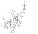
図1に、本発明に係る画像形成装置の一例として、タンデム型のカラー複写機の概略構成図を示す。
カラー複写機1は、本体中央部に位置する画像形成部19と、画像形成部19の下方に位置する給紙部15と、画像形成部19の上方に位置する画像読取部を有している。本例における画像形成装置は、線速が200mm/sで、作像可能なものとなされている。画像形成部19には、水平方向に延びる転写面を有する転写定着部材としての転写定着ベルト2が配置されている。転写定着ベルト2の上面には、色分解色と補色関係にある色の画像を形成するための構成が設けられている。具体的には、補色関係にある色のトナー(イエロー、マゼンタ、シアン、ブラック)による像を担持可能な像担持体としての感光体3Y、3M、3C、3Bが転写定着ベルト2の転写面に沿って並置されている。
Hereinafter, specific embodiments of the present invention will be described, but the present invention is not limited to the following examples.
(First embodiment)
FIG. 1 shows a schematic configuration diagram of a tandem type color copying machine as an example of an image forming apparatus according to the present invention.
The color copying machine 1 includes an
転写定着ベルト2は、多層構造を有しているものとし、具体的には、基材となるポリイミド樹脂(膜厚40μm)、ゴム(膜厚60μm)、フッ素樹脂(膜厚6μm)の構成を有するものが好適な例として挙げられる。前記ゴム層は、画像形成用の記録媒体の表面に凹凸がある場合に、確実に追従させるために必要なものであり、表面のフッ素樹脂層は、トナーや紙粉に対する離型性へ寄与するものである。
The
感光体3Y、3M、3C、3Bは、それぞれ、同方向に回転可能なドラム構造を有している。前記感光体それぞれの周囲には、回転過程において画像形成処理を実行する帯電装置4Y、4M、4C、4B、光書き込み手段としての書き込み装置5Y、5M、5C、5B、色別にカラートナーが収容された現像装置6Y、6M、6C、6B、1次転写装置7Y、7M、7C、7B、及びクリーニング装置8Y、8M、8C、8Bが配置されている。
各符号に付記しているアルファベットは、感光体3と同様、トナーの色別に対応している。
Each of the
The alphabet added to each symbol corresponds to the color of the toner as in the photosensitive member 3.
転写定着ベルト2は、駆動ローラ11と、従動機能を有するローラ9、10に掛け回されており、感光体3Y、3M、3C、3Bとの対峙位置において同方向に移動可能な構成を有している。駆動ローラ11と対向する位置には、転写定着ベルト2の表面をクリーニングするクリーニング装置13が設けられている。
The transfer and fixing
次に、実際の画像形成工程について感光体を特定して説明する。
先ず、感光体3Yの表面が、帯電装置4Yにより一様に帯電され、画像読取部からの画像情報に基づいて感光体3Y上に静電潜像が形成される。この静電潜像はイエローのトナーを収容した現像装置6Yによりトナー像として可視像化され、このトナー像は所定のバイアスが印加される一次転写装置7Yにより転写定着ベルト2上に1次転写される。
その他の感光体3M、3C、3Bについても、同様に画像形成がなされ、それぞれの色のトナー像が転写定着ベルト2上に順に転写されて重ね合わせられる。
Next, the actual image forming process will be described with the photoconductor identified.
First, the surface of the photoreceptor 3Y is uniformly charged by the charging device 4Y, and an electrostatic latent image is formed on the photoreceptor 3Y based on image information from the image reading unit. This electrostatic latent image is visualized as a toner image by a developing device 6Y containing yellow toner, and this toner image is primarily transferred onto the
The
画像転写を行った後、各感光体3上に残留したトナーは、それぞれのクリーニング装置8により除去される。その後、除電ランプ(図示せず)により各感光体3の電位が初期化され、次の作像工程に備えられる。 After the image transfer, the toner remaining on each photoconductor 3 is removed by each cleaning device 8. Thereafter, the potential of each photoconductor 3 is initialized by a static elimination lamp (not shown), and is prepared for the next image forming step.
従動ローラ9に対向する位置には、加圧部材(以下、加圧ローラとも言う)24が設けられている。加圧ローラ24は、転写定着ベルト2とニップN(以下、ニップ又は転写ニップともいう)を形成する機能を有している。この加圧ローラ24は、例えばアルミニウムよりなる金属製のパイプ状構造を有し、表面には離型層がコーティングされている。
A pressure member (hereinafter also referred to as a pressure roller) 24 is provided at a position facing the driven roller 9. The
ニップNの用紙搬送方向の上流側に、輻射加熱熱源(以下、ヒータともいう)121と、輻射加熱熱源121により加熱されて接触した記録媒体Pの表面を加熱する熱伝達部材120とが設けられている。
熱伝達部材120は、ヒートパイプや熱伝導率の高い銅などの材料で構成され、記録媒体Pとの接触面は、摺動のためにフッ素樹脂などの低摩擦材料の層が数μm形成されていても良い。図1の例では、熱伝達部材としての加熱ローラ120が設けられている。加熱ローラ120の径としては、装置に応じて適宜選択されるが、加熱ローラ120の熱容量低減による加熱効率アップから、20〜30mmが好ましい。
なお、図9に示すように、銅は熱伝導率と容積比熱とが極めて優れ、SUS304は容積比熱が極めて優れているため、熱伝達部材の材料として好適である。また、熱伝達部材の色としては、黒色に近い色が好ましい。加熱ローラ120の表層は、熱源側が放射率0.2以上の材質からなることが好ましい。具体的には、表層が金属材質の場合、黒またはそれに準ずる色に塗装または表面処理することで放射率を向上させることができる。これによって熱伝達する部材の熱吸収が向上して効率的に加熱することが出来、立ち上がり時間の短縮や連続通紙時の線速向上を図ることができる。さらに、熱容量の高い材質で構成することにより、安定した温度制御が行えるようになる。
A radiant heating heat source (hereinafter also referred to as a heater) 121 and a
The
As shown in FIG. 9, copper is excellent in heat conductivity and volume specific heat, and SUS304 is suitable as a material for the heat transfer member because it has extremely high volume specific heat. The color of the heat transfer member is preferably a color close to black. The surface layer of the
輻射加熱熱源121としては、輻射加熱可能な熱源であれば特に制限はないが、例えば、カーボンランプ、カーボンナノランプなどを用いれば、紙に対して熱吸収率の高い波長(2.5〜3μm)を効率的に照射することが可能となりエネルギー効率がアップする
輻射加熱熱源121は、反射板130によって被覆されているため、同じく反射板により少なくとも一部が被覆された加熱ローラ120は、効率的に輻射加熱される。
輻射加熱された加熱ローラ120は、全長に渡って熱伝達され高温に保持されながら、対向ローラ122によって用紙搬送速度と略同速同方向に図示しない駆動源によって回転駆動される。
加熱ローラ120の温度は、140〜200℃程度に制御され、記録媒体Pの表面を加熱するようになされている。
The radiant
The radiantly
The temperature of the
なお、記録媒体(紙)Pを加熱する工程において、紙の裏面に直径20μmの熱電対を固定し測定を行ったところ、加熱ローラ120の接触後、0〜20msにおいては、紙裏面の温度変化は5℃以内であったことが確かめられた。なお、紙は一般に汎用されているコピー用紙(リコー製コピー用紙6200)を適用した。
In the process of heating the recording medium (paper) P, a measurement was performed with a thermocouple having a diameter of 20 μm fixed to the back surface of the paper, and the temperature change on the back surface of the paper was 0 to 20 ms after contact with the
加熱ローラ120は、端部2箇所を圧縮バネ(スプリング)102によって記録媒体Pの方向へ加圧され、対向ローラ122との間に挟持された記録媒体Pと確実に一定時間(例えば20msec程度)接触して、記録媒体Pの表面を加熱する。
The
記録媒体Pの表面温度は、加熱ローラ120と対向ローラ122による挟持区間をそのまま抜けると低下するが、輻射加熱域130bにおいて、反射板130で形成された区画の開口部130aから漏れて照射される輻射熱により表面が加熱されることで温度低下が抑制される。
The surface temperature of the recording medium P decreases as it passes through the nipping section between the
開口部130aは、選択的に開閉可能な遮蔽機構を備え、例えば、記録媒体の厚みが100μm以上のときに開放され、搬送駆動が停止したときには閉鎖されるように制御される。
具体的には、開口部130aの前方又は後方に、選択的に開閉して開口部を塞いだり開放したりするシャッター131を設ける。シャッターは、ソレノイド等の駆動装置(図示せず)によって開閉するように構成しても良い。
例えば、用紙搬送方向の上流側に設けたセンサ133が搬送される用紙の厚みを検知し、厚みが100μm以上の場合には、加圧ローラ122に用紙が到達する前にシャッター131を開けて開口部130aを開放するように、100μm以下の場合には、加圧ローラ122に用紙が到達する前にシャッター131を閉じるように駆動制御する。これによって厚紙に比べて薄紙を不必要に加熱するのを防ぐことが出来、温度上昇が抑えられ、不必要な熱を外に逃がすことなく、エネルギー効率良く搬送できる。
シャッター131の動作は、完全に開閉するだけでなく、例えば、開口部の半分だけ閉じるような動作も可能である。これにより、過剰な輻射熱照射の調整を行うことが出来る。
また、用紙の種類はオペレータによって操作部から入力するようにしても同等の効果を発揮できる。
The opening 130a includes a shielding mechanism that can be selectively opened and closed, and is controlled to be opened when the thickness of the recording medium is 100 μm or more, for example, and is closed when the conveyance drive is stopped.
Specifically, a
For example, the
The operation of the
Further, the same effect can be obtained even if the operator inputs the paper type from the operation unit.
紙厚を検知するセンサ133は、用紙の搬送経路上に配設されており、用紙と接触することによる負荷変動から用紙の厚みを算出するものである。なお、操作パネルに設けられた用紙サイズ入力手段及び転写紙枚数入力手段からの入力によって紙厚を検知するようにしても良い。
The
さらに、用紙ジャム等で用紙搬送が検知されない場合においても、シャッター131を閉じるように駆動制御する。用紙ジャム時は、たとえヒータ121と用紙Pとが直接接触しなくても、滞留時間が長いことから用紙が発火して炎上する危険性がある。ただし、開放部を塞ぐことにより発火を防ぐことが出来る。
Further, even when paper conveyance is not detected due to a paper jam or the like, drive control is performed so that the
開口部130aは、例えば、網目状や格子状の部材で構成されることにより、ここから用紙Pが入り込んでヒータ120に接触して発火するのを防いでいる。
加熱された用紙Pは、従動ローラ9と加圧ローラ24とで形成されるニップNに搬送され、ここで転写定着ベルト2によって加熱溶融されたトナーTが紙表面に転写と同時に定着される。
本構成においては、開口部130aと転写定着ベルト2に載っているトナーTを近傍に配置することが出来るため、転写直前のトナーが加熱輻射され、ニップ部Nにおける転写定着の効率が向上する。転写定着ベルト2に対する加熱は、ニップNの直前において最小限行われるため、転写定着ベルト2の温度上昇は、ベルトが1回転する間に容易に冷却されて抑えられる。
The opening 130a is formed of, for example, a mesh-like or lattice-like member, and prevents the paper P from entering from here and coming into contact with the
The heated paper P is conveyed to a nip N formed by the driven roller 9 and the
In this configuration, since the toner T placed on the opening 130a and the transfer / fixing
給紙部15は、記録媒体としての用紙Pを積載収容する給紙トレイ14と、この給紙トレイ14内の用紙Pを最上のものから順に1枚ずつ分離して給紙する給紙コロ16と、給紙された用紙Pを搬送する搬送ローラ対17と、用紙Pが一旦停止され、斜めずれを修正された後転写定着ベルト2上の画像の先端と搬送方向の所定位置とが一致するタイミングでニップNに向けて送り出されるレジストローラ対18とを有している。
A
ところで、前述した感光体3Y、3M、3C、3Bから転写定着ベルト2上に1次転写されたトナー像T(以下、単にトナーともいう)は、所定のバイアス印加手段によるバイアス(従動ローラ11に印加されるバイアス(AC、パルスなどの重畳を含む))により、転写定着ベルト2に静電気力で転写される。
By the way, the toner image T (hereinafter also simply referred to as toner) that has been primarily transferred from the above-described
図1に示す画像形成装置においては、転写定着ベルト2に対する転写部と、最も上流側の感光体3Bに対する転写部との間に、転写定着ベルト2の温度を均等にするための均しローラ210が設けられている。
均しローラ210は、ヒートパイプや熱伝導率の高いグラファイト等の材料により構成されており、転写定着ベルト2に接触した状態で回転するようになされている。均しローラ210については、駆動ローラ11にかかるヒートパイプの機能を具備させて兼用させてもよい。
In the image forming apparatus shown in FIG. 1, a leveling
The leveling
転写定着ベルト2に転写されたトナー像Tは、ニップNにおいて記録媒体(紙)Pに定着されるまで、記録媒体(紙)Pからの熱量により加熱される。
従来公知のカラー画像形成装置においては、記録媒体(紙)による温度低下を考慮して白黒画像形成装置よりも1.5倍の熱量を与えることが必要とされていた。このために記録媒体(紙)が必要以上に加熱されてしまい、トナーとの密着性が高くなりすぎる傾向があった。
本実施形態においては、輻射加熱熱源121と、熱伝達部材120とによって記録媒体の表面のみを直前に加熱する構成であるため、トナーと記録媒体との境界の温度を制御することが可能となる。これにより記録媒体(紙)による温度低下を考慮して必要以上に加熱してしまうことが回避され、前述のように記録媒体(紙)の過熱を防止できるだけでなく、転写定着ベルト2の温度(定着設定温度)を低く維持できるようになる。また、充分な光沢を有する画像形成に好適な温度を独立に設定することができる。
The toner image T transferred to the
In a conventionally known color image forming apparatus, it is necessary to apply a heat amount 1.5 times that of a black and white image forming apparatus in consideration of a temperature drop due to a recording medium (paper). For this reason, the recording medium (paper) is heated more than necessary, and the adhesion to the toner tends to be too high.
In the present embodiment, since only the surface of the recording medium is heated immediately before by the radiant
本実施形態の画像形成装置によれば、比較的低温定着が可能な構成となされているので、画像形成の際の、いわゆるウォームアップ時間の短縮が図られるとともに、省エネルギー性にも優れている。また、作像部への伝熱も回避されているので、熱による部品の劣化が防止でき、装置の耐久性の向上が図られる。 According to the image forming apparatus of this embodiment, since it is configured to be able to fix at a relatively low temperature, the so-called warm-up time during image formation can be shortened and energy saving is also excellent. Further, since heat transfer to the image forming unit is also avoided, deterioration of the parts due to heat can be prevented, and durability of the apparatus can be improved.
上述したように、本発明の画像形成装置では、未定着トナー像を保持した用紙を単に加熱・加圧する従来の定着装置に対して、「転写定着装置」として位置付けられるものである。 As described above, the image forming apparatus of the present invention is positioned as a “transfer fixing apparatus” with respect to a conventional fixing apparatus that simply heats and presses a sheet holding an unfixed toner image.
(第2の実施形態)
次に、本発明の第2の実施形態について、図2を参照して説明する。
図2は、単一の感光体上に色重ねを行う、いわゆるIOI型カラー複写機である画像形成装置の一例である。なお、図2の画像形成装置において、上述した図1の画像形成装置と共通箇所においては同一符号を付し、説明は省略する。
(Second Embodiment)
Next, a second embodiment of the present invention will be described with reference to FIG.
FIG. 2 shows an example of an image forming apparatus which is a so-called IOI type color copying machine which performs color superposition on a single photoconductor. In the image forming apparatus of FIG. 2, the same reference numerals are given to the same parts as those of the image forming apparatus of FIG.
感光体上色重ね方式においては、感光体上の作像動作として、1色のトナーに対する帯
電、露光(書き込み)、現像までの工程を、多色のトナーについても一連の工程を単一の
感光体上で行う。
図1のように、一色毎に1つの感光体上に作像工程を行い、各色分の感光体を設けた構
成のものが、4連タンデム方式であるが、この感光体上色重ね方式は、4連タンデム方式
に比較して高速対応性に優れており、また、装置全体としての省スペース化、低コスト化
を図ることができる。
In the color superimposing method on the photoconductor, as the image forming operation on the photoconductor, the steps from charging, exposure (writing), and development to one color toner are performed, and a series of steps are also performed for a multicolor toner. Do it on the body.
As shown in FIG. 1, an image forming process is performed on one photoconductor for each color and a photoconductor for each color is provided in a quadruple tandem system. Compared with the quadruple tandem system, it is excellent in high-speed compatibility, and space saving and cost reduction of the entire apparatus can be achieved.
(第3の実施形態)
次に、本発明の第3の実施形態について、図3を参照して説明する。
図3の例では、熱伝達部材として板状体である搬送ガイド板132が設けられている。ガイド板132の板厚としては、装置に応じて適宜選択されるが、ガイド板132の熱容量低減による加熱効率アップから、1〜2mmが好ましい。
熱伝達部材の材料としては、熱伝導率の高いグラファイトや銅が好適である。また、熱伝達部材の色としては、黒色に近い色が好ましい。ガイド板132の少なくともヒータ121側(上側)の面は、放射率が0.2以上の材質からなることが好ましい。具体的には、表上側の面が金属材質の場合、黒またはそれに準ずる色に塗装または表面処理することで放射率を向上させる。これによって熱伝達する部材の熱吸収が向上して効率的に加熱することが出来、立ち上がり時間の短縮や連続通紙時の線速向上を図ることができる。さらに、熱容量の高い材質で構成することにより、安定した温度制御が行えるようになる。
(Third embodiment)
Next, a third embodiment of the present invention will be described with reference to FIG.
In the example of FIG. 3, a
As a material for the heat transfer member, graphite or copper having high thermal conductivity is suitable. The color of the heat transfer member is preferably a color close to black. It is preferable that at least the surface on the
ガイド板132の用紙Pとの接触面(下面)には、摺動のためにフッ素樹脂などの低摩擦材料の層が数μm形成されていても良い。また、ヒータ121の輻射熱によってガイド板132は全長に渡って熱伝達されて高温に保持され、搬送される用紙Pの表面に接触して紙表面に熱を伝達することで用紙Pを加熱している。
第1の実施態様として図1に示した装置と同様、用紙搬送方向下流側に開口部130aが設けられている。用紙PがニップNに受け渡されるまでの区間、搬送される用紙Pの表面がヒータ121の輻射熱で加熱される。対向ローラ122は、用紙搬送速度と略同速同方向に図示しない駆動源によって回転駆動される。対向ローラ122を発泡シリコン等の柔らかい材質で構成し、スプリング102でガイド板132を加圧すれば、搬送中のニップ幅が大きくなり、紙への接触時間が増え、たとえ用紙搬送速度がアップしても加熱時間が確保され、用紙Pを安定して加熱することが出来るようになる。
On the contact surface (lower surface) of the
As in the first embodiment, as in the apparatus shown in FIG. 1, an opening 130a is provided on the downstream side in the paper transport direction. During the period until the paper P is delivered to the nip N, the surface of the paper P being conveyed is heated by the radiant heat of the
(第4の実施形態)
次に、本発明の第4の実施形態について、図4を参照して説明する。
図4は、熱伝達部材を透明な回転体134で構成した例である。内側にヒータ121を固定したガラス等の透明ローラ134は、図示しない駆動装置によって用紙搬送方向、略同速に回転駆動される。用紙Pとの密着性向上の為、対向ローラ122がスプリング102によって裏側から加圧される。反射板130を近傍に配して輻射効率をアップすると共に、下流側に開放部を設けることで透明ローラ壁からの輻射熱をニップNまで搬送される用紙加熱に用いることが出来るようになる。
(Fourth embodiment)
Next, a fourth embodiment of the present invention will be described with reference to FIG.
FIG. 4 is an example in which the heat transfer member is configured by a transparent
次に、球形トナーの実施形態を説明する。
トナーの転写性(転写効率、忠実性)は目的とする画像の画質に影響を及ぼし、このトナーの転写性はトナーの形状に関与していることが知られている。
高画質化を達成すべくトナー形状の最適化を図るために検討したところ、ワーデル実用球形度φが0.8以上の値をもつトナーは転写性が良好であることが確かめられた。
Next, an embodiment of a spherical toner will be described.
It is known that toner transferability (transfer efficiency, fidelity) affects the image quality of a target image, and this toner transferability is related to the shape of the toner.
As a result of studies for optimizing the toner shape in order to achieve high image quality, it was confirmed that toner having a Wadel practical sphericity φ of 0.8 or more has good transferability.
ワーデル実用球形度φは、下記式により示される。
φ=(粒子投影面積に等しい円の直径)/(粒子投影像に外接する円の直径)
The Wardel practical sphericity φ is expressed by the following equation.
φ = (diameter of circle equal to particle projection area) / (diameter of circle circumscribing particle projection image)
具体的には、スライドグラス上にトナーを適当量とり、顕微鏡で拡大(500倍)し、任意の100個のトナーについて測定することで容易に計算できる。
このような条件を満たすトナーを適用することにより、2次転写効率を高められ、高画質化を図ることができる。
Specifically, it can be easily calculated by taking an appropriate amount of toner on a slide glass, enlarging (500 times) with a microscope, and measuring 100 arbitrary toners.
By applying a toner that satisfies such conditions, the secondary transfer efficiency can be increased and high image quality can be achieved.
トナーを構成する材料としては、従来公知のものをいずれも適用できる。結着樹脂としては、例えば、ポリエステル、ポリスチレン、ポリ−p−クロロスチレン、ポリビニルトルエン等のスチレン及びその置換体の単重合体、スチレン−p−クロロスチレン共重合体、スチレン−プロピレン共重合体、スチレン−ビニルトルエン共重合体、スチレン−ビニルナフタリン共重合体、スチレン−アクリル酸メチル共重合体、スチレン−アクリル酸エチル共重合体、スチレン−アクリル酸ブチル共重合体、スチレン−アクリル酸オクチル共重合体、スチレン−メタクリル酸メチル共重合体、スチレン−メタクリル酸エチル共重合体、スチレン−メタクリル酸ブチル共重合体、スチレン−α−クロルメタクリル酸メチル共重合体、スチレン−アクリロニトリル共重合体、 スチレン−ビニルメチルエーテル共重合体、スチレン−ビニルエチルエーテル共重合体、スチレン−ビニルメチルケトン共重合体、スチレン−ブタジエン共重合体、スチレンーイソプレン共重合体、スチレン−アクリロニトリル−インデン共重合体、スチレン−マレイン酸共重合体、スチレン−マレイン酸エステル共重合体などのスチレン系共重合体がいずれも適用できる。また、下記の樹脂を混合して用いてもよい。すなわち、例えば、ポリメチルメタクリレート、ポリブチルメタクリレート、ポリ塩化ビニル、ポリ酢酸ビニル、ポリエチレン、ポリプロピレン、ポリウレタン、ポリアミド、エポキシ樹脂、ポリビニルブチラール、ポリアクリル酸樹脂、ロジン、変性ロジン、テルペン樹脂、フェノール樹脂、脂肪族叉は脂環族炭化水素樹脂、芳香族系石油樹脂、塩素化パラフィン、パラフィンワックスが挙げられる。ポリエステル樹脂を含有させると、充分な定着性を得るためには好適である。特に結晶性ポリエステル樹脂は、紙接触時に十分に軟化溶融し、定着強度とともに色再現性の高い画像形成が可能となるため好適である。ポリエステル樹脂は、アルコールとカルボン酸との縮重合によって得られるが、用いられるアルコールとはポリエチレングリコール、ジエチレングリコール、トリエチレングリコール、1,2−プロピレングリコール、1,3−プロピレングリコール、1,4−ブタンジオール、ネオペンチルグリコール、1,4−ブテンジオール等のジオール類、1,4−ビス(ヒドロキシメチル)シクロヘキサン、ビスフェノールA、水素添加ビスフェノールA、ポリエキシエチレン化ビスフェノールA、ポリオキシプロピレン化ビスフェノールA等のエーテル化ビスフェノール類、これらを炭素数3〜22の飽和もしくは不飽和の炭化水素基で置換した2価のアルコール単体、その他の2価のアルコール単体を挙げることができる。また、ポリエステル樹脂を得るために用いられるカルボン酸としては、例えばマレイン酸、フマール酸、メサコン酸、シトラコン酸、イタコン酸、グルタコン酸、フタル酸、イソフタル酸、テレフタル酸、シクロヘキサンジカルボン酸、コハク酸、アジピン酸、セバチン酸、マロン酸、これらを炭素数3〜22の飽和もしくは不飽和の炭化水素基で置換した2価の有機酸単量体、これらの酸無水物、低級アルキルエステルとリノレイン酸の2量体、その他の2価の有機酸単量体を挙げることができる。 Any conventionally known material can be used as the material constituting the toner. As the binder resin, for example, styrene such as polyester, polystyrene, poly-p-chlorostyrene, polyvinyltoluene, and the like, a homopolymer of a substituted product thereof, a styrene-p-chlorostyrene copolymer, a styrene-propylene copolymer, Styrene-vinyltoluene copolymer, styrene-vinylnaphthalene copolymer, styrene-methyl acrylate copolymer, styrene-ethyl acrylate copolymer, styrene-butyl acrylate copolymer, styrene-octyl acrylate copolymer Polymer, styrene-methyl methacrylate copolymer, styrene-ethyl methacrylate copolymer, styrene-butyl methacrylate copolymer, styrene-α-chloromethyl methacrylate copolymer, styrene-acrylonitrile copolymer, styrene- Vinyl methyl ether copolymer, styrene Vinyl ethyl ether copolymer, styrene-vinyl methyl ketone copolymer, styrene-butadiene copolymer, styrene-isoprene copolymer, styrene-acrylonitrile-indene copolymer, styrene-maleic acid copolymer, styrene-maleic Any styrenic copolymer such as an acid ester copolymer can be applied. Moreover, you may mix and use the following resin. That is, for example, polymethyl methacrylate, polybutyl methacrylate, polyvinyl chloride, polyvinyl acetate, polyethylene, polypropylene, polyurethane, polyamide, epoxy resin, polyvinyl butyral, polyacrylic acid resin, rosin, modified rosin, terpene resin, phenol resin, Aliphatic or alicyclic hydrocarbon resins, aromatic petroleum resins, chlorinated paraffins and paraffin waxes may be mentioned. When a polyester resin is contained, it is suitable for obtaining sufficient fixability. In particular, the crystalline polyester resin is suitable because it is sufficiently softened and melted at the time of paper contact and can form an image with high color reproducibility as well as fixing strength. The polyester resin is obtained by condensation polymerization of alcohol and carboxylic acid, and the alcohol used is polyethylene glycol, diethylene glycol, triethylene glycol, 1,2-propylene glycol, 1,3-propylene glycol, 1,4-butane. Diols such as diol, neopentyl glycol, 1,4-butenediol, 1,4-bis (hydroxymethyl) cyclohexane, bisphenol A, hydrogenated bisphenol A, polyexethylenated bisphenol A, polyoxypropylenated bisphenol A, etc. The divalent alcohol simple substance which substituted these with the C3-C22 saturated or unsaturated hydrocarbon group, and other divalent alcohol simple substance can be mentioned. Examples of the carboxylic acid used to obtain the polyester resin include maleic acid, fumaric acid, mesaconic acid, citraconic acid, itaconic acid, glutaconic acid, phthalic acid, isophthalic acid, terephthalic acid, cyclohexanedicarboxylic acid, succinic acid, Adipic acid, sebacic acid, malonic acid, divalent organic acid monomers in which these are substituted with a saturated or unsaturated hydrocarbon group having 3 to 22 carbon atoms, acid anhydrides thereof, lower alkyl esters and linolenic acid Dimers and other divalent organic acid monomers can be mentioned.
バインダー樹脂であるポリエステル樹脂を得るためには、以上の2官能性単量体のみによる重合体のみでなく、3官能以上の多官能性単量体による成分を含有する重合体を用いることも好適である。かかる多官能性単量体である3価以上の多価アルコール単量体としては、例えばソルビトール、1,2,3,6−ヘキサンテトロール、1,4−サルビタン、ペンタエスリトール、ジペンタエスリトール、トリペンタエスリトール、蔗糖、1,2,4−ブタントリオール、1,2,5−ペンタントリオール、グリセロール、2−メチルプロパントリオール、2−メチル−1,2,4−ブタントリオール、トリメチロールエタン、トリメチロールプロパン、1.3.5−トリヒドロキシメチルベンゼン、その他を挙げることができる。また3価以上の多価カルボン酸単量体としては、例えば1,2,4−ペンゼントリカルボン酸、1,2,5−ペンゼントリカルボン酸、1,2,4−シクロヘキサントリカルボン酸、2,5,7−ナフタレントリカルボン酸、1,2,4−ナフタレントリカルボン酸、1,2,4−ブタントリカルボン酸、1,2,5−ヘキサントリカルボン酸、1,3−ジカルボキシル−2−メチル−2−メチレンカルボキシプロパン、テトラ(メチレンカルボキシル)メタン、1,2,7,8−オクタンテトラカルボン酸、エンボール3量体酸、これらの酸無水物、その他を挙げることができる。 In order to obtain a polyester resin which is a binder resin, it is also preferable to use not only a polymer based on the above bifunctional monomer but also a polymer containing a component based on a trifunctional or higher functional monomer. It is. Examples of the polyhydric alcohol monomer having three or more valences that are such polyfunctional monomers include sorbitol, 1,2,3,6-hexanetetrol, 1,4-sarbitane, pentaesitol, dipenta. Esitol, tripentaerythritol, sucrose, 1,2,4-butanetriol, 1,2,5-pentanetriol, glycerol, 2-methylpropanetriol, 2-methyl-1,2,4-butanetriol , Trimethylolethane, trimethylolpropane, 1.3.5-trihydroxymethylbenzene, and others. Examples of the trivalent or higher polyvalent carboxylic acid monomer include 1,2,4-benzenetricarboxylic acid, 1,2,5-benzenetricarboxylic acid, 1,2,4-cyclohexanetricarboxylic acid, 5,7-naphthalenetricarboxylic acid, 1,2,4-naphthalenetricarboxylic acid, 1,2,4-butanetricarboxylic acid, 1,2,5-hexanetricarboxylic acid, 1,3-dicarboxyl-2-methyl-2 -Methylenecarboxypropane, tetra (methylenecarboxyl) methane, 1,2,7,8-octanetetracarboxylic acid, embol trimer acid, acid anhydrides thereof, and the like.
また、トナーには、転写定着時の転写定着部材表面でのトナーの離型性を向上する目的で、離型剤を含有させることが好ましい。離型剤としては、従来公知のものを適用できるが、例えば、脱遊離脂肪酸型カルナウバワックス、モンタンワックス、及び酸化ライスワックス、エステルワックスを単独又は組み合わせて使用することができる。
カルナウバワックスとしては、微結晶のものが良く、酸価が5以下であり、トナーバインダー中に分散した時の粒子径が1μm以下の粒径であるものが好ましい。
モンタンワックスについては、一般に鉱物より精製されたモンタン系ワックスを指し、カルナウバワックス同様、微結晶であり、酸価が5〜14であることが好ましい。
酸化ライスワックスは、米ぬかワックスを空気酸化したものであり、その酸価は10〜30が好ましい。
各ワックスの酸価が各々の範囲未満であった場合、低温定着温度が上昇し低温定着化が不十分となる。逆に酸価が各々の範囲を超えた場合、コールドオフセット温度が上昇し低温定着化が不十分となる。
ワックスの添加量としてはバインダー樹脂100重量部に対して1〜15重量部、好ましくは3〜10重量部の範囲で用いられる。1重量部未満では、その離型効果が薄く所望の効果が得られにくい。又15重量部を超えた場合はキャリアへのスペントが顕著になる等の問題が生じることが確かめられた。
The toner preferably contains a release agent for the purpose of improving the releasability of the toner on the surface of the transfer fixing member during transfer fixing. As the mold release agent, conventionally known ones can be applied. For example, de-free fatty acid type carnauba wax, montan wax, oxidized rice wax, and ester wax can be used alone or in combination.
The carnauba wax is preferably a microcrystalline one, having an acid value of 5 or less and a particle size of 1 μm or less when dispersed in a toner binder.
The montan wax generally refers to a montan wax refined from minerals, and like a carnauba wax, it is microcrystalline and preferably has an acid value of 5 to 14.
The oxidized rice wax is obtained by air-oxidizing rice bran wax, and the acid value is preferably 10-30.
When the acid value of each wax is less than the respective range, the low temperature fixing temperature rises and the low temperature fixing becomes insufficient. On the contrary, when the acid value exceeds each range, the cold offset temperature rises and the low-temperature fixing becomes insufficient.
The added amount of the wax is 1 to 15 parts by weight, preferably 3 to 10 parts by weight with respect to 100 parts by weight of the binder resin. If it is less than 1 part by weight, the releasing effect is thin and the desired effect is difficult to obtain. In addition, when the amount exceeds 15 parts by weight, it has been confirmed that problems such as significant spent on the carrier occur.
また、その他の外添加剤として、トナーの流動性を向上させる目的で、シリカ、酸化チタン、アルミナ等、更には必要に応じて脂肪酸金属塩類やポリフッ化ビニリデン等を添加しても良い。
特に転写定着はトナーを十分に加熱することが可能なため、サブミクロンの大粒径シリカ等の添加剤を比較的多量に用いても定着性、定着温度に影響を与えないため、流動性・転写性を考慮した外添処方が可能である。
As other external additives, for the purpose of improving the fluidity of the toner, silica, titanium oxide, alumina, and the like, and if necessary, fatty acid metal salts and polyvinylidene fluoride may be added.
In particular, since transfer fixing can sufficiently heat the toner, even if a relatively large amount of an additive such as a submicron large particle size silica is used, the fixing property and fixing temperature are not affected. It is possible to prescribe external additives in consideration of transferability.
なお、これまで本発明を図面に示した実施形態をもって説明してきたが、本発明は図面に示した実施形態に限定されるものではなく、他の実施形態、追加、変更、削除など、当業者が想到することができる範囲内で変更することができ、いずれの態様においても本発明の作用・効果を奏する限り、本発明の範囲に含まれるものである。 Although the present invention has been described with the embodiments shown in the drawings, the present invention is not limited to the embodiments shown in the drawings, and other embodiments, additions, modifications, deletions, etc. Can be changed within the range that can be conceived, and any embodiment is included in the scope of the present invention as long as the effects and advantages of the present invention are exhibited.
1 画像形成装置(カラー複写機)
2 転写定着部材(転写定着ベルト、転写定着ローラ)
3 感光体
4 帯電装置
5 書き込み装置
6 現像装置
7 一次転写装置
8 クリーニング装置
9、10 従動ローラ
11 駆動ローラ
12 クリーニング装置
14 給紙トレイ
15 給紙部
16 給紙コロ
17 搬送ローラ対
18 レジストローラ対
19 画像形成部
22 転写定着ベルト
24 加圧部材(加圧ローラ)
102 スプリング
111 摺動材
120 熱伝達部材(加熱ローラ、ローラ状回転部材)
121 複写加熱熱源(ヒータ)
122 対向ローラ
130 反射板
130a 開口部(輻射開口部)
130b 輻射加熱域
131 シャッター
132 熱伝達部材(ガイド板、板状体)
133 センサ
210 均しローラ
N ニップ部
P 記録媒体(用紙)
T トナー像
1 Image forming device (color copier)
2 Transfer fixing member (transfer fixing belt, transfer fixing roller)
DESCRIPTION OF SYMBOLS 3 Photoconductor 4 Charging device 5 Writing device 6 Developing device 7 Primary transfer device 8 Cleaning device 9, 10 Driven
102
121 Copy heating heat source (heater)
122
130b
133
T Toner image
Claims (11)
前記ニップの前記記録媒体搬送方向の上流側に配置される輻射加熱熱源と、
前記輻射加熱熱源により加熱されて接触した前記記録媒体を加熱する熱伝達部材と、
前記輻射加熱熱源および前記熱伝達部材の少なくとも一部を被覆するとともに、一部に開口部を有する反射部材と、を備え、
前記ニップと前記熱伝達部材との間に、前記開口部から漏れる前記輻射加熱熱源からの輻射熱により前記記録媒体が加熱される輻射加熱域が形成されることを特徴とする転写定着装置。 A transfer fixing member to which an image is transferred; and a pressure member that is pressed against the transfer fixing member to form a nip, and has at least a configuration in which the image is pressed and fixed on a recording medium that passes through the nip. With
A radiation heating heat source disposed upstream of the nip in the recording medium conveyance direction;
A heat transfer member that heats and contacts the recording medium heated by the radiant heat source ; and
A reflection member that covers at least a portion of the radiant heating heat source and the heat transfer member and has an opening in a portion thereof ,
Between the heat transfer member before and Symbol nip, transfer-fixing device characterized by radiant heating zone in which the recording medium is heated by radiant heat from the radiant heating heat leaking from the opening.
前記転写定着部材のニップ部に対する上流側に配置され、該転写定着部材に転写される画像を担持する感光体が、複数色のトナーを重ねる方式によりカラー画像の形成を行うことを特徴とする画像形成装置。 A transfer fixing device according to any one of claims 1 to 9,
An image, which is disposed upstream of the nip portion of the transfer and fixing member and carries an image to be transferred to the transfer and fixing member, forms a color image by a method of superposing a plurality of color toners. Forming equipment.
ワーデル実用球形度φが0.8以上であるトナーを現像剤として用いることを特徴とする画像形成装置。
A transfer fixing device according to any one of claims 1 to 9,
An image forming apparatus using a toner having a Wadel practical sphericity φ of 0.8 or more as a developer.
Priority Applications (2)
| Application Number | Priority Date | Filing Date | Title |
|---|---|---|---|
| JP2008179239A JP5233455B2 (en) | 2008-07-09 | 2008-07-09 | Transfer fixing device and image forming apparatus |
| US12/458,316 US8571452B2 (en) | 2008-07-09 | 2009-07-08 | Transfer and fixing device using radiant heating and image forming apparatus using same |
Applications Claiming Priority (1)
| Application Number | Priority Date | Filing Date | Title |
|---|---|---|---|
| JP2008179239A JP5233455B2 (en) | 2008-07-09 | 2008-07-09 | Transfer fixing device and image forming apparatus |
Publications (2)
| Publication Number | Publication Date |
|---|---|
| JP2010019995A JP2010019995A (en) | 2010-01-28 |
| JP5233455B2 true JP5233455B2 (en) | 2013-07-10 |
Family
ID=41530412
Family Applications (1)
| Application Number | Title | Priority Date | Filing Date |
|---|---|---|---|
| JP2008179239A Expired - Fee Related JP5233455B2 (en) | 2008-07-09 | 2008-07-09 | Transfer fixing device and image forming apparatus |
Country Status (2)
| Country | Link |
|---|---|
| US (1) | US8571452B2 (en) |
| JP (1) | JP5233455B2 (en) |
Families Citing this family (13)
| Publication number | Priority date | Publication date | Assignee | Title |
|---|---|---|---|---|
| JP2011150242A (en) | 2010-01-25 | 2011-08-04 | Ricoh Co Ltd | Image forming apparatus |
| JP2011186040A (en) * | 2010-03-05 | 2011-09-22 | Ricoh Co Ltd | Fixing device for separating recording medium by compressed air injection, and image forming apparatus |
| US8666270B2 (en) | 2010-06-21 | 2014-03-04 | Ricoh Company, Ltd. | Image forming apparatus |
| JP2012193015A (en) | 2011-03-16 | 2012-10-11 | Ricoh Co Ltd | Sheet separating device, fixing device, and image forming apparatus |
| JP6148817B2 (en) | 2011-08-15 | 2017-06-14 | 株式会社リコー | Fixing apparatus and image forming apparatus |
| KR101842617B1 (en) * | 2011-10-19 | 2018-03-27 | 에스프린팅솔루션 주식회사 | Power control apparatus and image forming apparatus having it |
| JP6260868B2 (en) | 2014-05-27 | 2018-01-17 | 株式会社リコー | Image forming apparatus |
| JP6823337B2 (en) * | 2014-09-16 | 2021-02-03 | ジュン シア,リ | Fluid discharge system |
| JP6519158B2 (en) | 2014-11-28 | 2019-05-29 | 株式会社リコー | Image forming device |
| US9846396B2 (en) | 2015-10-14 | 2017-12-19 | Ricoh Company, Ltd. | Transfer device and image forming apparatus incorporating same |
| DE102016120016A1 (en) * | 2016-10-20 | 2018-04-26 | Aquis Sanitär AG | Monitoring device for a sanitary facility |
| JP7263722B2 (en) * | 2018-09-26 | 2023-04-25 | 富士フイルムビジネスイノベーション株式会社 | Fixing belt, fixing device, process cartridge, image forming apparatus, and base material for fixing belt |
| JP7172688B2 (en) * | 2019-02-08 | 2022-11-16 | 株式会社リコー | DRYING DEVICE, IMAGE FORMING APPARATUS, AND DRYING DEVICE CONTROL METHOD |
Family Cites Families (50)
| Publication number | Priority date | Publication date | Assignee | Title |
|---|---|---|---|---|
| JPS57164773A (en) * | 1981-04-03 | 1982-10-09 | Konishiroku Photo Ind Co Ltd | Method and device for transferring and fixing of toner image |
| JPS5840571A (en) * | 1981-09-04 | 1983-03-09 | Fuji Photo Film Co Ltd | Fixing device for electrophotography |
| US4430412A (en) * | 1981-11-13 | 1984-02-07 | Konishiroku Photo Industry Co., Ltd. | Method and apparatus for transferring and fixing toner image using controlled heat |
| JPS5885464A (en) * | 1981-11-16 | 1983-05-21 | Konishiroku Photo Ind Co Ltd | Method and device for transfer and fixing of toner image |
| DE3242231A1 (en) * | 1981-11-16 | 1983-05-26 | Konishiroku Photo Industry Co., Ltd., Tokyo | IMAGE DISPLAY DEVICE |
| US4518976A (en) * | 1982-11-17 | 1985-05-21 | Konishiroku Photo Industry Co., Ltd. | Recording apparatus |
| JPS6093466A (en) * | 1983-10-27 | 1985-05-25 | Canon Inc | Control method of image formaing device provided with resist shutter |
| JPS60242486A (en) * | 1984-05-17 | 1985-12-02 | Canon Inc | Recorder |
| JPH0694300B2 (en) | 1989-07-07 | 1994-11-24 | 日立プラント建設株式会社 | Deep-fried dough sorting device |
| US6141524A (en) * | 1999-07-26 | 2000-10-31 | Xerox Corporation | Release agent management for transfuse systems |
| US6795676B2 (en) * | 2001-06-01 | 2004-09-21 | Ricoh Company, Ltd | Sheet wrapping avoidable fixing apparatus and image forming apparatus |
| JP2003162184A (en) * | 2001-11-26 | 2003-06-06 | Ricoh Co Ltd | Image forming device |
| JP2004145260A (en) * | 2002-07-04 | 2004-05-20 | Ricoh Co Ltd | Fixing apparatus, image forming apparatus, and record medium recycling method |
| JP4408339B2 (en) * | 2003-01-10 | 2010-02-03 | 株式会社リコー | Fixing roller, fixing device and image forming apparatus |
| US7139520B2 (en) * | 2003-06-20 | 2006-11-21 | Ricoh Company, Ltd. | Fixing device, nipping device, and image forming apparatus |
| JP2005037879A (en) | 2003-06-26 | 2005-02-10 | Ricoh Co Ltd | Intermediate transfer device, fixing device and image forming apparatus |
| JP2005049566A (en) * | 2003-07-31 | 2005-02-24 | Canon Inc | Transfer fixing device and image forming apparatus with the same |
| US7254362B2 (en) * | 2003-11-07 | 2007-08-07 | Ricoh Company, Ltd. | Fixing device, image forming apparatus using the fixing device, and heat insulating member |
| JP4558307B2 (en) * | 2003-11-28 | 2010-10-06 | 株式会社リコー | Fixing apparatus and image forming apparatus |
| JP4697573B2 (en) * | 2004-01-23 | 2011-06-08 | 富士ゼロックス株式会社 | Image forming apparatus |
| US7299003B2 (en) * | 2004-01-29 | 2007-11-20 | Ricoh Company, Limited | Fixing unit and image forming apparatus providing a quick start-up and reduction in energy consumption |
| JP2005242085A (en) * | 2004-02-27 | 2005-09-08 | Konica Minolta Business Technologies Inc | Image forming apparatus |
| JP4368711B2 (en) * | 2004-03-18 | 2009-11-18 | 株式会社リコー | Transfer fixing device, image forming apparatus including the same, and transfer fixing method |
| JP4455144B2 (en) * | 2004-04-27 | 2010-04-21 | キヤノン株式会社 | Image forming apparatus |
| JP2006010886A (en) * | 2004-06-24 | 2006-01-12 | Ricoh Co Ltd | Fixing device, transfer and fixing device, and image forming apparatus |
| JP2006047960A (en) * | 2004-07-09 | 2006-02-16 | Ricoh Co Ltd | Fixing device and image forming apparatus using it |
| JP2006030249A (en) | 2004-07-12 | 2006-02-02 | Ricoh Co Ltd | Fixing device and image forming apparatus |
| JP4194540B2 (en) * | 2004-07-27 | 2008-12-10 | キヤノン株式会社 | Image forming apparatus |
| US20060113624A1 (en) * | 2004-11-29 | 2006-06-01 | Silicon-Based Technology Corp. | LOCOS-based Schottky barrier diode and its manufacturing methods |
| JP4674081B2 (en) * | 2004-12-20 | 2011-04-20 | 株式会社リコー | Fixing apparatus and image forming apparatus |
| JP4333583B2 (en) * | 2005-01-07 | 2009-09-16 | コニカミノルタビジネステクノロジーズ株式会社 | Image forming apparatus |
| JP2007025237A (en) * | 2005-07-15 | 2007-02-01 | Ricoh Co Ltd | Fixing device and image forming apparatus |
| US7613419B2 (en) * | 2005-08-30 | 2009-11-03 | Ricoh Company, Ltd. | Image forming apparatus and image forming method characterized by a particular nip time |
| JP4834485B2 (en) * | 2005-09-16 | 2011-12-14 | 株式会社リコー | Transfer fixing device and image forming apparatus |
| JP2007212754A (en) * | 2006-02-09 | 2007-08-23 | Ricoh Co Ltd | Fixing device and image forming apparatus using same |
| US7643767B2 (en) * | 2006-03-02 | 2010-01-05 | Ricoh Co., Ltd. | Transfer-fixing unit and image forming apparatus for enhanced image quality |
| US7711301B2 (en) * | 2006-03-10 | 2010-05-04 | Ricoh Company, Ltd. | Image transfer device for image forming apparatus |
| JP4707188B2 (en) * | 2006-03-17 | 2011-06-22 | 株式会社リコー | Image forming apparatus and toner |
| JP2007322794A (en) * | 2006-06-01 | 2007-12-13 | Ricoh Co Ltd | Image forming apparatus and fixing device used therein |
| JP2007328222A (en) * | 2006-06-09 | 2007-12-20 | Canon Inc | Fixing device |
| JP4834502B2 (en) * | 2006-09-19 | 2011-12-14 | 株式会社リコー | Image forming apparatus |
| JP4963910B2 (en) * | 2006-09-19 | 2012-06-27 | 株式会社リコー | Image forming method |
| JP4889028B2 (en) * | 2007-02-15 | 2012-02-29 | 株式会社リコー | Transfer fixing device and image forming apparatus |
| JP2008216628A (en) * | 2007-03-05 | 2008-09-18 | Ricoh Co Ltd | Transfer/fixing device and image forming apparatus |
| JP4877803B2 (en) * | 2007-03-08 | 2012-02-15 | 株式会社リコー | Transfer fixing device and image forming apparatus |
| US7869752B2 (en) * | 2007-06-23 | 2011-01-11 | Ricoh Company Limited | Cleaning device, fixing device, and image forming apparatus |
| JP2009003380A (en) | 2007-06-25 | 2009-01-08 | Ricoh Co Ltd | Image forming device |
| JP5181553B2 (en) * | 2007-07-09 | 2013-04-10 | 株式会社リコー | Transfer fixing device and image forming apparatus |
| JP4955492B2 (en) * | 2007-09-14 | 2012-06-20 | 株式会社リコー | Image forming apparatus |
| JP2009115956A (en) * | 2007-11-05 | 2009-05-28 | Ricoh Co Ltd | Image transfer fixation apparatus and image formation apparatus |
-
2008
- 2008-07-09 JP JP2008179239A patent/JP5233455B2/en not_active Expired - Fee Related
-
2009
- 2009-07-08 US US12/458,316 patent/US8571452B2/en not_active Expired - Fee Related
Also Published As
| Publication number | Publication date |
|---|---|
| US20100014897A1 (en) | 2010-01-21 |
| JP2010019995A (en) | 2010-01-28 |
| US8571452B2 (en) | 2013-10-29 |
Similar Documents
| Publication | Publication Date | Title |
|---|---|---|
| JP5233455B2 (en) | Transfer fixing device and image forming apparatus | |
| JP5200722B2 (en) | Image recording device | |
| JP5181553B2 (en) | Transfer fixing device and image forming apparatus | |
| US8103199B2 (en) | Developing device, and image forming method and process cartridge using the developing device | |
| US7907881B2 (en) | Transfer-fixing device, image forming apparatus, and transfer-fixing method | |
| JP5339080B2 (en) | Transfer fixing device, and image forming apparatus and image forming method using the transfer fixing device | |
| JP5050591B2 (en) | Image forming apparatus | |
| JP2007322794A (en) | Image forming apparatus and fixing device used therein | |
| EP1965271A1 (en) | Transfer-Fixing Device, Image Forming Apparatus, and Transfer-Fixing Method | |
| JP2009115956A (en) | Image transfer fixation apparatus and image formation apparatus | |
| JP2010032935A (en) | Image forming apparatus and image forming method | |
| JP5305104B2 (en) | Belt drive device and image forming apparatus | |
| JP2010204235A (en) | Heat transfer fixing device and image forming apparatus | |
| JP4758262B2 (en) | Transfer fixing device and image forming apparatus having the same | |
| JP4914090B2 (en) | Image forming apparatus | |
| JP2011039328A (en) | Transfer fixing device and image forming apparatus | |
| JP5190795B2 (en) | Transfer fixing device and image forming apparatus | |
| JP2007212754A (en) | Fixing device and image forming apparatus using same | |
| JP4958585B2 (en) | Transfer fixing device and image forming apparatus | |
| JP2009003380A (en) | Image forming device | |
| US20240077820A1 (en) | Fixing device and image forming apparatus therewith | |
| JP5446347B2 (en) | Transfer fixing device and image forming apparatus | |
| JP2008003538A (en) | Image forming apparatus | |
| JP5369788B2 (en) | Transfer fixing device and image forming apparatus | |
| JP5106259B2 (en) | Transfer fixing device and image forming apparatus |
Legal Events
| Date | Code | Title | Description |
|---|---|---|---|
| A621 | Written request for application examination |
Free format text: JAPANESE INTERMEDIATE CODE: A621 Effective date: 20110324 |
|
| A131 | Notification of reasons for refusal |
Free format text: JAPANESE INTERMEDIATE CODE: A131 Effective date: 20121127 |
|
| A521 | Written amendment |
Free format text: JAPANESE INTERMEDIATE CODE: A523 Effective date: 20130121 |
|
| TRDD | Decision of grant or rejection written | ||
| A01 | Written decision to grant a patent or to grant a registration (utility model) |
Free format text: JAPANESE INTERMEDIATE CODE: A01 Effective date: 20130226 |
|
| A61 | First payment of annual fees (during grant procedure) |
Free format text: JAPANESE INTERMEDIATE CODE: A61 Effective date: 20130311 |
|
| FPAY | Renewal fee payment (event date is renewal date of database) |
Free format text: PAYMENT UNTIL: 20160405 Year of fee payment: 3 |
|
| LAPS | Cancellation because of no payment of annual fees |