JP2006010886A - Fixing device, transfer and fixing device, and image forming apparatus - Google Patents
Fixing device, transfer and fixing device, and image forming apparatus Download PDFInfo
- Publication number
- JP2006010886A JP2006010886A JP2004185744A JP2004185744A JP2006010886A JP 2006010886 A JP2006010886 A JP 2006010886A JP 2004185744 A JP2004185744 A JP 2004185744A JP 2004185744 A JP2004185744 A JP 2004185744A JP 2006010886 A JP2006010886 A JP 2006010886A
- Authority
- JP
- Japan
- Prior art keywords
- fixing
- fixing member
- recording paper
- heating
- fixing device
- Prior art date
- Legal status (The legal status is an assumption and is not a legal conclusion. Google has not performed a legal analysis and makes no representation as to the accuracy of the status listed.)
- Pending
Links
Images


Classifications
-
- G—PHYSICS
- G03—PHOTOGRAPHY; CINEMATOGRAPHY; ANALOGOUS TECHNIQUES USING WAVES OTHER THAN OPTICAL WAVES; ELECTROGRAPHY; HOLOGRAPHY
- G03G—ELECTROGRAPHY; ELECTROPHOTOGRAPHY; MAGNETOGRAPHY
- G03G15/00—Apparatus for electrographic processes using a charge pattern
- G03G15/20—Apparatus for electrographic processes using a charge pattern for fixing, e.g. by using heat
- G03G15/2003—Apparatus for electrographic processes using a charge pattern for fixing, e.g. by using heat using heat
- G03G15/2014—Apparatus for electrographic processes using a charge pattern for fixing, e.g. by using heat using heat using contact heat
- G03G15/2039—Apparatus for electrographic processes using a charge pattern for fixing, e.g. by using heat using heat using contact heat with means for controlling the fixing temperature
- G03G15/2042—Apparatus for electrographic processes using a charge pattern for fixing, e.g. by using heat using heat using contact heat with means for controlling the fixing temperature specially for the axial heat partition
-
- G—PHYSICS
- G03—PHOTOGRAPHY; CINEMATOGRAPHY; ANALOGOUS TECHNIQUES USING WAVES OTHER THAN OPTICAL WAVES; ELECTROGRAPHY; HOLOGRAPHY
- G03G—ELECTROGRAPHY; ELECTROPHOTOGRAPHY; MAGNETOGRAPHY
- G03G2215/00—Apparatus for electrophotographic processes
- G03G2215/16—Transferring device, details
- G03G2215/1676—Simultaneous toner image transfer and fixing
- G03G2215/1695—Simultaneous toner image transfer and fixing at the second or higher order transfer point
-
- G—PHYSICS
- G03—PHOTOGRAPHY; CINEMATOGRAPHY; ANALOGOUS TECHNIQUES USING WAVES OTHER THAN OPTICAL WAVES; ELECTROGRAPHY; HOLOGRAPHY
- G03G—ELECTROGRAPHY; ELECTROPHOTOGRAPHY; MAGNETOGRAPHY
- G03G2215/00—Apparatus for electrophotographic processes
- G03G2215/20—Details of the fixing device or porcess
- G03G2215/2003—Structural features of the fixing device
- G03G2215/2006—Plurality of separate fixing areas
-
- G—PHYSICS
- G03—PHOTOGRAPHY; CINEMATOGRAPHY; ANALOGOUS TECHNIQUES USING WAVES OTHER THAN OPTICAL WAVES; ELECTROGRAPHY; HOLOGRAPHY
- G03G—ELECTROGRAPHY; ELECTROPHOTOGRAPHY; MAGNETOGRAPHY
- G03G2215/00—Apparatus for electrophotographic processes
- G03G2215/20—Details of the fixing device or porcess
- G03G2215/2003—Structural features of the fixing device
- G03G2215/2016—Heating belt
- G03G2215/2025—Heating belt the fixing nip having a rotating belt support member opposing a pressure member
- G03G2215/2032—Heating belt the fixing nip having a rotating belt support member opposing a pressure member the belt further entrained around additional rotating belt support members
-
- G—PHYSICS
- G03—PHOTOGRAPHY; CINEMATOGRAPHY; ANALOGOUS TECHNIQUES USING WAVES OTHER THAN OPTICAL WAVES; ELECTROGRAPHY; HOLOGRAPHY
- G03G—ELECTROGRAPHY; ELECTROPHOTOGRAPHY; MAGNETOGRAPHY
- G03G2215/00—Apparatus for electrophotographic processes
- G03G2215/20—Details of the fixing device or porcess
- G03G2215/2003—Structural features of the fixing device
- G03G2215/2016—Heating belt
- G03G2215/2035—Heating belt the fixing nip having a stationary belt support member opposing a pressure member
Abstract
Description
本発明は、電子写真方式の画像形成装置における定着装置に関し、特に定着装置の端部における温度の上昇防止を図ったものに関する。 The present invention relates to a fixing device in an electrophotographic image forming apparatus, and more particularly to a fixing device that prevents temperature rise at an end portion of the fixing device.
従来、電子写真の定着装置には、表面が非粘着性の弾性体で内部に加熱源を有する定着ローラと、弾性体で被覆された加圧ローラを設け、適当な圧力を加えて回転する両ローラ間にトナーを転写した記録紙を通過させ、熱と圧力によりトナーを定着させる熱ローラ定着方式が多く使用されている。しかし、この熱ローラ定着方式は定着ローラの熱容量が大きいため、定着ローラを定着に必要な所定の温度にまで加熱昇温させる時間が長目に必要で、そのため装置のウォームアップ時間を長く取っているものが多い。また、定着ローラの温度を維持するために多くの電力を必要とするため、定着装置あるいは画像形成装置全体での消費電力を大幅に増加させている。 2. Description of the Related Art Conventionally, an electrophotographic fixing device is provided with a fixing roller having a non-adhesive elastic body and a heating source inside, and a pressure roller covered with the elastic body. A hot roller fixing system is often used in which a recording sheet with toner transferred between rollers is passed and the toner is fixed by heat and pressure. However, since this heat roller fixing method has a large heat capacity of the fixing roller, it takes a long time to heat up the fixing roller to a predetermined temperature required for fixing, and therefore it takes a long time to warm up the apparatus. There are many things. In addition, since a large amount of power is required to maintain the temperature of the fixing roller, the power consumption of the entire fixing device or image forming apparatus is greatly increased.
そこで近年、これらの問題を解決するため、芯金を薄肉にして定着ローラを低熱容量化した装置構成や、低熱容量のベルト面で記録紙上のトナーを定着するベルト定着方式が開発されている。このような定着部材の低熱容量化は、定着部材を所定の温度に加熱するだけで定着に必要な熱エネルギーが得られるので、ウォームアップ時間を短くできる。 Therefore, in recent years, in order to solve these problems, an apparatus configuration in which the cored bar is thin and the fixing roller has a low heat capacity, and a belt fixing method for fixing toner on recording paper on a low heat capacity belt surface have been developed. Such a reduction in the heat capacity of the fixing member can shorten the warm-up time because the heat energy necessary for fixing can be obtained simply by heating the fixing member to a predetermined temperature.
ところが、特にこのような低熱容量の定着部材を用いた定着装置においては、小サイズ記録紙を多数枚連続して通紙した場合、定着部材の非通紙領域である端部温度が上昇して高温になり、定着部材の寿命に影響することがある。また、記録紙端部が中央部に比べて温度が高くなり、光沢度が増すため、記録紙端部と中央部で記録紙に光沢ムラが生じてしまうことがある。さらには非通紙領域が高温度になるので、小サイズ連続通紙直後に大サイズ記録紙へ切り換ると、ホットオフセットや巻き付きジャムが発生することもある。 However, in particular, in a fixing device using such a fixing member having a low heat capacity, when a large number of small-size recording sheets are continuously passed, the end temperature that is a non-sheet passing region of the fixing member increases. High temperature may affect the life of the fixing member. Further, since the temperature at the edge of the recording paper is higher than that at the central portion and the glossiness is increased, gloss unevenness may occur on the recording paper at the edge and the central portion of the recording paper. Furthermore, since the non-sheet passing area is at a high temperature, hot offset or winding jam may occur when switching to a large size recording sheet immediately after small size continuous sheet passing.
そこで、これらの問題を解決するため、各種の方法が提案されている。特許文献1に開示されている技術では、定着ローラ(定着回転部材)の軸方向に分割された複数の磁性体コアと、磁性体コアにそれぞれ備えられた励磁コイルとを有し、中央部加熱コイルへの電力供給量に応じて、端部加熱コイルへの電力供給量を制御する制御手段を備えている。 Therefore, various methods have been proposed to solve these problems. The technique disclosed in Patent Document 1 includes a plurality of magnetic cores divided in the axial direction of a fixing roller (fixing rotating member), and excitation coils respectively provided in the magnetic cores, and heating the central portion. Control means for controlling the power supply amount to the end heating coil according to the power supply amount to the coil is provided.
また特許文献2に開示されている技術では、相互に異なるサイズのシートの通紙幅領域における加熱ローラを渦電流によりそれぞれ加熱する第1及び第2の磁場発生手段を有し、通紙されるシートのサイズに対応した磁場発生手段により加熱ローラを加熱している。 Further, in the technique disclosed in Patent Document 2, the first and second magnetic field generating means for heating the heating rollers in the sheet passing width regions of sheets having different sizes from each other by eddy currents are provided. The heating roller is heated by a magnetic field generating means corresponding to the size of.
さらに特許文献3に開示されている技術では、小サイズ紙に対応する配光分布を有する第1ヒータと、それ以外の端部に対応する配光分布を有する第2ヒータと、大サイズ紙に対応する配光分布を有する第3ヒータを設けており、特許文献4に開示されている技術では、定着ベルトの外側に最大幅で誘導加熱手段を有し、加熱ローラ内に用紙サイズに応じて、独立して制御する2個以上の輻射熱源を有し、特許文献5に開示されている技術では、定着ローラ内にハロゲンヒータを持ち、小サイズ紙対応として、定着ローラ外側に近接して、小サイズ幅の磁石を配置し、渦電流で加熱するようになっている。 Furthermore, in the technique disclosed in Patent Document 3, a first heater having a light distribution corresponding to small size paper, a second heater having a light distribution corresponding to the other end, and a large size paper are used. A third heater having a corresponding light distribution is provided. In the technique disclosed in Patent Document 4, induction heating means is provided at the maximum width outside the fixing belt, and the heating roller has a size corresponding to the paper size. , Having two or more radiant heat sources to be controlled independently, the technique disclosed in Patent Document 5 has a halogen heater in the fixing roller, and is close to the outside of the fixing roller for small size paper, A small-sized magnet is placed and heated by eddy current.
しかしながら、特許文献1に開示されている技術のように、磁性体コアに励磁コイルを巻くのは手間がかかり、また磁場発生手段は取付けに精度が必要なため、組み付け性が悪い。またこれの磁場発生手段はコストが高く、端部温度上昇対策として磁場発生手段を複数設けると極めてコストアップとなる。特に特許文献1の技術では、磁場発生手段を複数設けているので組み付け性がかなり悪く、またコストアップにもなる。また中央部加熱コイルへの電力供給量に応じて、端部加熱コイルへの電力供給量を制御するので制御回路が複雑となり、さらにコストアップとなる。またコイルを分割するとコイルのつなぎ目で温度ムラが起き、画像に光沢ムラが発生してしまう。 However, as in the technique disclosed in Patent Document 1, it takes time and effort to wind the exciting coil around the magnetic core, and the magnetic field generating means requires accuracy for mounting, so that the assembling property is poor. In addition, these magnetic field generating means are expensive, and if a plurality of magnetic field generating means are provided as a countermeasure against an end temperature rise, the cost is extremely increased. In particular, in the technique of Patent Document 1, since a plurality of magnetic field generating means are provided, the assemblability is considerably poor and the cost is increased. Further, since the power supply amount to the end heating coil is controlled according to the power supply amount to the central heating coil, the control circuit becomes complicated and the cost is further increased. Further, when the coil is divided, temperature unevenness occurs at the joints of the coils, and uneven glossiness occurs in the image.
同様に特許文献2の技術では、磁場発生手段を複数設けているため、極めてコストアップとなる。また磁場発生手段はスペースをとるにもかかわらず磁場発生手段を2列配置しているため、定着装置が大型化してしまう。またハロゲンヒータは、ハロゲンヒータ自体の熱容量があるため、電磁誘導発熱に比べて発熱効率が悪く、電磁誘導発熱に対しウォームアップ時間が長くなってしまう。 Similarly, in the technique of Patent Document 2, since a plurality of magnetic field generating means are provided, the cost is extremely increased. Further, since the magnetic field generating means has two rows even though it takes a space, the fixing device is increased in size. In addition, since the halogen heater has the heat capacity of the halogen heater itself, the heat generation efficiency is lower than that of electromagnetic induction heat generation, and the warm-up time becomes longer for electromagnetic induction heat generation.
また特許文献3の技術では、熱源がハロゲンヒータのみなので、電磁誘導発熱を用いた装置に比べて発熱効率が悪く、ウォームアップ時間が長く、特許文献4の技術では、誘導加熱手段と2個以上の輻射熱源とを備えるが、通紙サイズの変化には輻射熱源だけで対応しており、特許文献5の技術では、ハロゲンヒータと磁石とが通紙サイズの変化に関わらない配置となっている。 In the technique of Patent Document 3, since the heat source is only a halogen heater, the heat generation efficiency is poor and the warm-up time is long compared to a device using electromagnetic induction heat generation. In the technique of Patent Document 4, two or more induction heating means are used. However, in the technique of Patent Document 5, the halogen heater and the magnet are arranged so as not to be affected by the change in the sheet passing size. .
本発明は、上述した従来の問題点にかんがみ、ウォームアップ時間が短く、組み付けが容易で、コストを抑えることができ、効率よく定着部材の端部温度上昇を防止することができる定着装置とこれを用いた画像形成装置を提供することを目的とする。 In view of the above-described conventional problems, the present invention provides a fixing device and a fixing device that can shorten the warm-up time, can be easily assembled, can reduce costs, and can efficiently prevent an increase in the end temperature of the fixing member. An object of the present invention is to provide an image forming apparatus using the above.
本発明の請求項1に係る定着装置は、磁場発生手段と、該磁場発生手段の磁界の作用で電磁誘導発熱する定着部材と、該定着部材と相互圧接してニップ部を形成する加圧部材を有し、前記ニップ部に記録紙を通紙して記録紙上の未定着画像を定着する定着装置において、前記電磁誘導発熱で加熱対応する通紙幅サイズとは異なる通紙幅サイズに加熱対応する輻射加熱手段を少なくとも1つ以上有し、電磁誘導による発熱と輻射加熱による発熱とを、通紙する記録紙サイズにより制御手段で独立して制御することを特徴とする。 According to a first aspect of the present invention, there is provided a fixing device comprising: a magnetic field generating means; a fixing member that generates electromagnetic induction heat by the action of the magnetic field of the magnetic field generating means; and a pressure member that forms a nip portion by mutual pressure contact with the fixing member. In a fixing device for fixing a non-fixed image on the recording paper by passing the recording paper through the nip portion, the radiation corresponding to the paper passing width size different from the paper passing width size corresponding to the heating by the electromagnetic induction heat generation is provided. At least one heating unit is provided, and heat generation by electromagnetic induction and heat generation by radiation heating are independently controlled by the control unit depending on the size of the recording paper to be passed.
同請求項2に係るものは、請求項1の定着装置において、電磁誘導による発熱が大サイズ記録紙の加熱に対応し、前記輻射加熱による発熱が小サイズ記録紙の加熱に対応することを特徴とする。 According to the second aspect of the present invention, in the fixing device of the first aspect, the heat generated by electromagnetic induction corresponds to the heating of the large size recording paper, and the heat generated by the radiation heating corresponds to the heating of the small size recording paper. And
同請求項3に係るものは、請求項1または2の定着装置において、前記磁場発生手段が前記定着部材の外側に位置し、前記輻射熱源が前記定着部材の内側に位置することを特徴とする。 According to a third aspect of the present invention, in the fixing device according to the first or second aspect, the magnetic field generating means is located outside the fixing member, and the radiant heat source is located inside the fixing member. .
同請求項4に係るものは、請求項1ないし3のいずれかの定着装置において、記録紙上の未定着画像が定着可能である前記定着部材の定着温度を設定し、前記定着部材が該定着温度に昇温する際は電磁誘導発熱により前記定着部材を発熱させ、前記定着部材が前記定着温度に昇温した後の小サイズ記録紙の通紙時は、前記輻射熱源により前記定着部材を加熱することを特徴とする。 According to a fourth aspect of the present invention, in the fixing device according to any one of the first to third aspects, a fixing temperature of the fixing member capable of fixing an unfixed image on a recording sheet is set, and the fixing member is set to the fixing temperature. When the temperature is increased, the fixing member is heated by electromagnetic induction heat generation, and the fixing member is heated by the radiant heat source when the small-size recording paper is passed after the fixing member is heated to the fixing temperature. It is characterized by that.
同請求項5に係るものは、請求項1ないし3のいずれかの定着装置において、記録紙上の未定着画像が定着可能である前記定着部材の定着温度を設定し、前記定着部材が該定着温度に昇温する際は電磁誘導発熱により前記定着部材を発熱させ、前記定着部材が定着温度に昇温した後の小サイズ記録紙の通紙時も、引き続き電磁誘導発熱により前記定着部材を発熱させ、さらに前記輻射熱源により前記定着部材を加熱することを特徴とする。 According to the fifth aspect of the present invention, in the fixing device according to any one of the first to third aspects, a fixing temperature of the fixing member capable of fixing an unfixed image on a recording sheet is set, and the fixing member is set to the fixing temperature. When the temperature of the fixing member is increased, the fixing member is heated by electromagnetic induction heat generation, and the fixing member is continuously heated by electromagnetic induction heat generation even when a small-size recording sheet is passed after the fixing member is heated to the fixing temperature. Further, the fixing member is heated by the radiant heat source.
同請求項6に係るものは、請求項1ないし5のいずれかの定着装置において、前記定着部材はベルト状部材であり、輻射熱源は前記定着部材の内側に位置することを特徴とする。 According to a sixth aspect of the present invention, in the fixing device according to any one of the first to fifth aspects, the fixing member is a belt-like member, and a radiant heat source is located inside the fixing member.
同請求項7に係る転写定着装置は、像担持体上に帯電したトナーまたは液体により未定着画像を形成し、該未定着画像を中間転写体に転写し、次に該中間転写体に転写された未定着画像を少なくとも離型層を有する転写定着部材に転写した後、さらに該転写定着部材上で未定着画像を加熱し、記録紙に定着させる転写定着装置において、前記転写定着部材の近傍に、磁場発生手段と、少なくとも1個以上の輻射加熱手段を配し、前記転写定着部材を前記磁場発生手段の磁界の作用で電磁誘導発熱させ、該電磁誘導発熱で加熱対応する通紙幅サイズと前記輻射加熱手段で加熱対応する通紙幅サイズを異ならせ、前記電磁誘導発熱と前記輻射加熱手段を、通紙する記録紙サイズにより制御手段で独立して制御することを特徴とする。
The transfer and fixing device according to
本発明の請求項8に係る画像形成装置は、請求項1ないし6のいずれかの定着装置または請求項7の転写定着装置を備えることを特徴とする。 An image forming apparatus according to an eighth aspect of the present invention includes the fixing device according to any one of the first to sixth aspects or the transfer fixing device according to the seventh aspect.
本発明は、小サイズ連続通紙時の定着部材の端部温度上昇を効果的に防止することができ、磁場発生手段を2個設けて定着部材の端部温度上昇対策とする場合に比べて組み付け性が良く、磁場発生手段を2個設けて定着部材の端部温度上昇対策とする場合に比してコストを低減することができ、しかもウォームアップ時間を短くすることができる。 The present invention can effectively prevent an increase in the end temperature of the fixing member at the time of small-size continuous paper feeding, as compared with a case where two magnetic field generating means are provided as a countermeasure for the end temperature increase of the fixing member. The assemblability is good, and the cost can be reduced and the warm-up time can be shortened as compared with the case where two magnetic field generating means are provided to prevent the end member temperature from rising.
以下本発明を実施するための最良の形態を、図に示す実施例を参照して説明する。 The best mode for carrying out the present invention will be described below with reference to the embodiments shown in the drawings.
まず本発明の実施対象となるカラー画像形成装置の一例での構成を説明する。ここで説明するカラー画像形成装置は、画像読み取り装置100と画像形成部200、及び手差し給紙装置300、給紙部400等を備えるともに、画像形成部200には定着装置21を備え、かつ複数の感光体1A、2A、3A、4Aを同一平面状に配列し、図の矢印方向に回転するものである。感光体1A〜4Aは、光導電性を有する有機または無機材料で構成されている。
First, the configuration of an example of a color image forming apparatus that is an object of the present invention will be described. The color image forming apparatus described here includes an
電子写真法を用いたフルカラー画像形成装置としては、色分解重ね合わせ転写方式が一般に使用されている。この方式の画像形成装置では、原稿を青、赤、緑の3色に色分解した画像情報光を各々原稿読取部で読み取り、その各色光の強度レベルをもとにして画像演算処理を行って得られたイエロー(Y)、シアン(C)、マゼンタ(M)、黒(BK)の各色で現像すべき書込画像データに基づいて、4つの感光体1A〜4A上に光書込を行い、得られた静電潜像を各感光体1A〜4Aに対して設けたイエロー、シアン、マゼンタ、黒の現像剤を内蔵する現像器1B、2B、3B、4Bで現像する。 As a full-color image forming apparatus using electrophotography, a color separation superposition transfer method is generally used. In this type of image forming apparatus, image information light obtained by separating a document into three colors of blue, red, and green is read by a document reading unit, and image calculation processing is performed based on the intensity level of each color light. Based on the obtained writing image data to be developed in each color of yellow (Y), cyan (C), magenta (M), and black (BK), optical writing is performed on the four photoconductors 1A to 4A. The obtained electrostatic latent images are developed by developing devices 1B, 2B, 3B, and 4B containing yellow, cyan, magenta, and black developers provided for the respective photoreceptors 1A to 4A.
図示の例では、各色分解画像情報はカラー画像形成装置本体の上部に設けた原稿読取部29で光学的に色分解し、3つのCCD20・・で各々読み取り、その出力信号を基に演算処理して得た各色データにより、感光体1A〜4Aに対設したレーザ書込装置1D、2D、3D、4Dにより光書込を行う。
In the illustrated example, each color separation image information is optically color-separated by a
感光体1A〜4Aは、それぞれ帯電装置1E、2E、3E、4Eにより負に帯電させ、光書込の行われた部分を負帯電トナーにより反転現像する。帯電装置には、コロトロン、スコロトロンなど、コロナ放電により電荷を発生させて像担持体表面に散布する方式のものが多く用いられる。現像器の配列は、給紙側から1B、2B、3B、4Bをそれぞれイエロー、シアン、マゼンタ、黒トナー用としており、この順で順次に正のコロナにより重ね転写を行う。転写ベルト25はポリエステルフイルムなどの誘電体から形成してあり、転写チャージャ1C、2C、3C、4Cにより正に帯電させるので、記録紙の分離後に転写ベルト25を除電装置26により除電する。除電装置26は転写ベルト25の両面からチャージャで負のACコロナ放電を行い、転写ベルト25の蓄積電荷を中和(除電)して転写ベルト25を初期化する。また転写ベルト25の残留トナーはクリーニングユニット22によりクリーニングする。
The photoreceptors 1A to 4A are negatively charged by the charging devices 1E, 2E, 3E, and 4E, respectively, and the portion where the optical writing has been performed is reversely developed with negatively charged toner. As the charging device, a device such as a corotron or a scorotron that generates a charge by corona discharge and disperses it on the surface of the image carrier is often used. As for the arrangement of the developing units, 1B, 2B, 3B, and 4B are respectively used for yellow, cyan, magenta, and black toners from the sheet feeding side, and the overlapping transfer is sequentially performed with a positive corona in this order. The transfer belt 25 is formed of a dielectric material such as a polyester film, and is positively charged by the
分離装置28は、記録紙の上面からチャージャで負のACコロナ放電を行い、記録紙の蓄積電荷を中和(除電)し、記録紙が転写ベルト25から分離する際の剥離放電によるトナーのチリを防止する。転写後、記録紙は転写ベルト25から分離され、定着装置21でトナー像を定着させ、カラー画像を得る。
The separation device 28 performs negative AC corona discharge with the charger from the upper surface of the recording paper, neutralizes (charges out) the accumulated charge of the recording paper, and removes toner dust due to peeling discharge when the recording paper is separated from the transfer belt 25. To prevent. After the transfer, the recording paper is separated from the transfer belt 25 and the toner image is fixed by the fixing
以下、図面に基づき本発明の実施例について説明する。 Embodiments of the present invention will be described below with reference to the drawings.
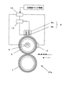
図2に本発明を適用する定着装置21aの概略構成図を示す。この定着装置21aは、定着ローラ6と加圧ローラ7でニップを形成し、フェライト8aと励磁コイル8bとからなる磁場発生手段8と、輻射熱源であるハロゲンヒータ9を有している。定着ローラ6は、導電性の芯金または芯金の表面に導電性層を有する。定着ローラ6の周囲には、定着ローラ6の温度を検出する温度検出手段13を配置し、定着ローラ6の温度を一定に保つように温度検出手段13から出される信号に基づいて、制御部15によって励磁コイル8b、またはハロゲンヒータ9への通電を制御する。励磁コイル8bへの通電においては、制御部15が励磁回路14を制御し、励磁コイル8bへの電力供給を増減する。そして磁場発生手段8により発生する磁場の中で定着ローラ6の導電層に渦電流が発生し、この渦電流が定着ローラ6の導電層の抵抗によってジュール熱に変換され、定着ローラ6が発熱する。
FIG. 2 shows a schematic configuration diagram of a
定着ローラ6は、例えば磁性体ステンレスの芯金を有し、その表面に弾性層としてシリコ−ンゴム層を設け、さらにその上に離型層としてPFAチューブを被覆したものとすることができる。また定着ローラ6としては、磁性体ステンレスの芯金の表面にフッ素樹脂層を設けた構成でも良い。加圧ローラ7は、定着ローラ6と同じ構成とすることができる。
The fixing
ここで本実施例の定着装置21aでは、磁場発生手段8及びハロゲンヒータ9は、それぞれ異なるサイズの記録紙幅を加熱するように配置してある。すなわち図3に示すように、磁場発生手段8を定着ローラ6の大サイズ記録紙の通紙幅領域を発熱させるように配置し、ハロゲンヒータ9を定着ローラ6の小サイズ記録紙の通紙幅領域を加熱するように配置してある。励磁コイル8bまたはハロゲンヒータ9への通電の切り換えは、記録紙サイズ情報を制御部15に送り、その記録紙サイズ情報に基づき制御部15によって行う。記録紙サイズ情報が大サイズ記録紙の場合は、励磁コイル8bへ通電し、記録紙サイズ情報が小サイズ記録紙の場合はハロゲンヒータ9へ通電する。記録紙サイズ情報は、原稿サイズ検知による情報や、データ転送時の原稿ザイズ情報、または選択トレイのサイズ情報から得ることができる。
Here, in the
従って本実施例の定着装置では、異なる記録紙幅サイズに加熱対応する熱源を有し、記録紙幅サイズに対応する熱源で加熱するので、小サイズ記録紙連続通紙時の端部温度上昇を防止できる。既述のように、磁場発生手段8はコイルを巻く手間がかかり、また取付けに精度が必要なため、組み付け性が悪く、しかもコストが高いため、定着部材の端部温度上昇対策として磁場発生手段8を複数設置すると、極めてコストアップとなる。そこで本実施例では、磁場発生手段8は1個とし、端部温度上昇対策としての熱源は輻射熱源を用いるようにして、磁場発生手段8を複数設ける場合に比べて組み付け性を容易にし、コストアップも抑えている。 Therefore, the fixing device of the present embodiment has a heat source corresponding to heating for different recording paper width sizes, and is heated by a heat source corresponding to the recording paper width size, so that it is possible to prevent an increase in end temperature during continuous passage of small size recording paper. . As described above, the magnetic field generating means 8 takes time and effort to wind a coil, and since it requires precision for mounting, the assembling property is poor and the cost is high. If a plurality of 8 are installed, the cost is extremely increased. Therefore, in this embodiment, the number of the magnetic field generating means 8 is one, and the radiation source is used as a heat source as a countermeasure against the temperature rise at the end portion. The up is also suppressed.
なお図2では、定着ローラ6の内側にハロゲンヒータ9を配するように示したが、定着ローラ6の外側にハロゲンヒータ9を配置しても良い。また輻射熱源として1個のハロゲンヒータ9で説明したが、記録紙のサイズに応じた輻射熱源を複数設置しても良い。
In FIG. 2, the
本発明を適用した定着装置の実施例2について図4により説明する。
本実施例の定着装置21bでは、定着ローラ6の周囲に定着ローラ6の中央部の温度を検出する温度検出手段13と、定着ローラ6の端部の温度を検出する端部温度検出手段16を配置し、温度検出手段13及び端部温度検出手段16から出される信号に基づいて、制御部17によって励磁コイル8bまたはハロゲンヒータ9への通電を制御する。端部温度検出手段16は、図3に示すように、小サイズ記録紙通紙領域と大サイズ記録紙通紙領域の間に設置する。上記以外の構成は実施例1の構成と同様であり、実施例1と同様の符号を付して示す。
Embodiment 2 of the fixing device to which the present invention is applied will be described with reference to FIG.
In the
ここで本実施例の定着装置21bでは、記録紙上の未定着画像が定着可能である定着ローラ6の定着温度と、定着ローラ6の端部上限温度と端部下限温度を設定する。端部上限温度は定着温度より高く設定する。定着ローラ6が定着温度に昇温するまでは、定着ローラ6を磁場発生手段8により電磁誘導発熱させる。定着ローラ6が定着温度に昇温後、小サイズ記録紙の連続通紙時において、端部温度検出手段16によって検出された定着ローラ6の温度が端部上限温度を超えた場合、励磁コイル8bへの通電を止め、ハロゲンヒータ9への通電に切り替える。またその後、端部温度検出手段16によって検出された定着ローラ6の温度が端部下限温度を下回った場合、ハロゲンヒータ9への通電を止め、励磁コイル8bへの通電に切り替える。
Here, in the
従って本実施例の定着装置21bでは、小サイズ記録紙の連続通紙時においても端部温度上昇を防止できる。また実施例1と同様に、磁場発生手段8は1個とし、端部温度上昇対策としての熱源は輻射熱源を用いるので、磁場発生手段8を複数設ける場合に対し、組み付け性を容易にし、コストアップも抑えることができる。また定着ローラ6が定着温度に昇温するまでは、定着ローラ6の加熱効率が高い電磁誘導で発熱させるので、熱源がハロゲンヒータ9のみの場合に対し、ウォームアップ時間を短くできる。
Therefore, in the
本発明を適用した定着装置の実施例3について図5により説明する。
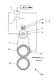
本実施例の定着装置21cは、定着ローラ30と、テンションをかける加熱ローラ31と、加圧ローラ32を備え、定着ローラ30と加熱ローラ31間にエンドレスの定着ベルト18が張設してある。加圧ローラ32は、定着ベルト18を挟んで定着ローラ30に圧接する。表面に未定着トナー像を担持した記録紙は、定着ベルト18を介して定着ローラ30と加圧ローラ32のニップ部で加熱、加圧され、トナー像を定着される。
Embodiment 3 of the fixing device to which the present invention is applied will be described with reference to FIG.
The fixing
定着ベルト18を挟んで加熱ローラ31の周囲には、フェライト8aと励磁コイル8bとからなる磁場発生手段8を配置し、また加熱ローラ31内部には、ハロゲンヒータ19を備えている。加熱ローラ31は磁性体ステンレスで導電性を有する。定着ベルト18の周囲には、定着ベルト18の温度を検出する温度検出手段13を配置し、定着ベルト18の温度を一定に保つように温度検出手段13から出される信号に基づいて、制御部15によって励磁コイル8bまたはハロゲンヒータ19への通電を制御する。励磁コイル8bへの通電においては、温度検出手段13から出される信号に基づいて制御部15が励磁回路14を制御し、励磁コイル8bへの電力供給を増減する。そして磁場発生手段8により発生する磁場の中で加熱ローラ31導電層に渦電流が発生し、この渦電流が加熱ローラ31導電層の抵抗によってジュール熱に変換され、加熱ローラ31が発熱する。
Around the
ここで磁場発生手段8及びハロゲンヒータ19は、先に説明した実施例1、2と同様に、それぞれ異なるサイズの記録紙幅を加熱するように配置し、磁場発生手段8は定着ベルト18の大サイズ記録紙の通紙幅領域を発熱させ、ハロゲンヒータ19は定着ベルト18の小サイズ記録紙の通紙幅領域を加熱する。磁場発生手段8またはハロゲンヒータ9への通電の切り換えは、実施例1と同様である。
Here, the magnetic field generating means 8 and the
また定着ベルト18の基体には、耐熱性樹脂や、金属から形成されたエンドレスのベルト状基体を用いることができる。耐熱性樹脂の材質としては、ポリイミド、ポリアミドイド、ポリエーテルケトン(PEEK)等を使用し、金属ベルトの材質としては、ニッケル、アルミニウム、鉄等を使用することができる。それらの厚さは、100μm以下の薄肉のものが望ましい。また表面は、記録紙及びトナー像と加圧接触するため離型性が必要であり、かつ耐熱性、耐久性に優れたものが好ましい。そのため、定着ベルト18の表層は耐熱離型層(フッ素系樹脂、高離型シリコ−ンゴム等を被覆した構成とするとよい。フッ素樹脂は、吹きつけ等により基体表面に塗装し、加熱融着させることにより表面離型層を形成できる。高離型シリコ−ンゴム層は、ゴム硬度25〜65度(JIS A硬度計)、厚さが100〜300umの範囲が良好な定着姓及び熱応答性を得る条件として望ましい。また定着ベルト18の別の構成としては、ポリイミド等の耐熱性樹脂の基体にシリコ−ンゴム等の弾性体層を設け、さらにその弾性体層の上にフッ素樹脂、PFAチューブ等の離型層を設け、OHP透明性、均一定着においてより良好な定着画像を得られるようにすることができる。
As the base of the fixing
定着ローラ30は、アルミニウム芯金の外周に耐熱弾性体、例えば発泡シリコーンゴムや液状シリコーンゴムで構成した弾性層を備えているものとすることができる。加圧ローラ32は、鉄またはアルミニウムの芯金外周にフッ素系ゴム、シリコーンゴム等の耐熱弾性層と、その上にフッ素系樹脂からなる表面離型層を形成したものとすることができる。加圧ローラ32の内側には加圧ローラ32の温度上昇を加速させるため、ハロゲンヒータ等の熱源を設けても良い。定着ローラ30あるいは加圧ローラ32は、図示しない駆動手段により駆動する。
The fixing
従って本実施例の定着装置21cでは、小サイズ記録紙の連続通紙時においても端部温度上昇を防止できる。また実施例1と同様に、磁場発生手段8を複数設ける場合に対し、組み付け性を容易にし、コストアップも抑えることができる。また定着ベルト18が定着温度に昇温するまでは、加熱効率が高い電磁誘導発熱で熱容量の小さい加熱ローラ31と定着ベルト18を加熱するので、ウォームアップ時間をより短くできる。ここで磁場発生手段8及びハロゲンヒータ19の通電制御は実施例1と同様としたが、定着ベルト18の端部温度を検出する端部温度検出手段を設け、実施例2の通電制御と同様にしても良い。実施例1と同様な構成要素については、実施例1と同様の符号を付して示してある。
Therefore, in the fixing
本発明を適用した定着装置の実施例4について図6により説明する。
本実施例の定着装置21dは、定着ベルト33と定着固定部材36と加圧ローラ34を有し、定着固定部材36は定着ベルト33を介して加圧ローラ34に圧接する。定着固定部材36は、鉄、ステンレス、またはアルミ等の金属材料からなる支持部材36aと、シリコーンゴムあるいは発泡シリコーンゴムからなる弾性部材36bと、ガラス繊維樹脂等からなる低摩擦部材シート36cで構成できる。加圧ローラ34は、芯金の周りに発泡層を有し、その表面をPFAチューブで被覆し、図示しない駆動手段によって回転駆動する。定着ベルト33の構成は実施例3の定着ベルト18と同様である。
Embodiment 4 of the fixing device to which the present invention is applied will be described with reference to FIG.
The fixing
定着ベルト33の周囲には、フェライト8aと励磁コイル8bとからなる磁場発生手段8を配置し、また定着ベルト33内部には、ハロゲンヒータ35を備えている。定着ベルト33の周囲には、定着ベルト33の温度を検出する温度検出手段13を配置し、実施例1と同様に、制御部15によって励磁コイル8bまたはハロゲンヒータ35への通電を制御する。
Around the fixing
ここで磁場発生手段8及びハロゲンヒータ35は、実施例1と同様にそれぞれ異なるサイズの記録紙幅を加熱するように配置してあり、磁場発生手段8は定着ベルト33の大サイズ記録紙の通紙幅領域を発熱させ、ハロゲンヒータ35は定着ベルト33の小サイズ記録紙の通紙幅領域を加熱する。磁場発生手段8またはハロゲンヒータ35への通電の切り換えは、実施例1と同様である。
Here, the magnetic field generating means 8 and the
従って本実施例の定着装置21dでは、小サイズ記録紙の連続通紙時においても端部温度上昇を防止できる。また実施例1と同様に、磁場発生手段8を複数設ける場合に比べて組み付け性を容易にし、コストアップも抑えることができる。また定着ベルト33が定着温度に昇温するまでは、加熱効率が高い電磁誘導発熱で熱容量の小さい定着ベルト33のみを加熱するので、ウォームアップ時間をさらに短くできる。ここで磁場発生手段8及びハロゲンヒータ35の通電制御は実施例1と同様としたが、定着ベルト33の端部温度を検出する端部温度検出手段を設け、実施例2の通電制御と同様にしても良い。実施例1と同様な構成要素については、実施例1と同様の符号を付して示してある。
Therefore, in the
本発明を適用した定着装置の実施例5について図7により説明する。
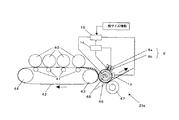
上記各実施例の説明では、帯電−露光−現像−転写−定着からなる電子写真プロセスで説明しているが、トナーを中間転写体から用紙へ転写するのではなく、中間転写体42から転写定着部材46に転写する電子写真の変形例でも、本発明が適用できることは明らかである。
Embodiment 5 of the fixing device to which the present invention is applied will be described with reference to FIG.
In the description of each of the above embodiments, the electrophotographic process including charging, exposure, development, transfer, and fixing is described. However, the toner is not transferred from the intermediate transfer member to the sheet, but is transferred and fixed from the intermediate transfer member. It is obvious that the present invention can be applied to the modified example of the electrophotography transferred to the
二次転写部においては必要に応じて既知の所望の電位差(AC、パルスなどの重畳を含む)を設け、画像の移動方向を制御する。二次転写部材43に対し、中間転写体42を介して転写定着部材46を設ける。ここで転写定着部材46に、中間転写体42上のトナーを転写するためのバイアスを印加することもできる。転写定着部材46と加圧部材47のニップ部においても、オフセットを防ぐ手段として電位差を設けても良い。電位差の発生手段はバイアス印加、アース、除電など公知の方法があり、電流制御・電圧制御などが利用可能である。ツェナーダイオードなどを用いて、一定の電位差を保つ方法も有効である。他の構成部品としては、像担持体40、一次転写部材41、中間転写体支持部材44を備えている。
In the secondary transfer portion, a known desired potential difference (including superposition of AC, pulse, etc.) is provided as necessary to control the moving direction of the image. A
転写定着部材46の周囲には、フェライト8aと励磁コイル8bとからなる磁場発生手段8を配置し、また転写定着部材46の内部には、ハロゲンヒータ48を備えている。転写定着部材46の周囲には、転写定着部材46の温度を検出する温度検出手段13を配置し、実施例1と同様に、制御部15によって励磁コイル8bまたはハロゲンヒータ48への通電を制御する。
Around the transfer and fixing
ここで磁場発生手段8及びハロゲンヒータ48は、実施例1と同様に、それぞれ異なるサイズの記録紙幅を加熱するように配置してあり、磁場発生手段8は転写定着部材46の大サイズ記録紙の通紙幅領域を発熱させ、ハロゲンヒータ48は転写定着部材46の小サイズ記録紙の通紙幅領域を加熱する。磁場発生手段8またはハロゲンヒータ48への通電の切り換えは、実施例1と同様である。
Here, the magnetic field generating means 8 and the
従って本実施例の定着装置21eでは、小記録紙の連続通紙時においても端部温度上昇を防止できる。また本実施例の転写に関して、二次転写は常に一定の相手部材、すなわち転写定着部材46に行うので、安定して高画質な画像を得られる。また、トナーの一部は熱で軟化することも、転写時の画像の散りを防ぐため高画質となる。
Therefore, in the
なお、磁場発生手段8及びハロゲンヒータ48の通電制御は実施例1と同様としたが、転写定着部材46の端部温度を検出する端部温度検出手段を設け、実施例2の通電制御と同様にしても良い。実施例1と同様な構成要素については、実施例1と同様の符号を付して示してある。
The energization control of the magnetic field generating means 8 and the
本実施例の定着及び熱に関して述べると、二次転写部の中間転写体42への熱移動は、トナーを介して表層のみへ行われるため、中間転写体42の温度上昇は最小限となる。従って中間転写体42の温度上昇による問題点も生じにくい。また、トナー加熱時間は十分設定可能であり、用紙を従来と同程度の時間で加熱できる。さらに特筆すべきは、中間転写体42の加熱時間は最小のまま、トナー加熱時間と用紙加熱時間を各々設定可能である点である。従って、光沢などの画質に重要なトナー加熱時間と、用紙への密着性に重要な用紙加熱時間を自由に設定でき、無駄に用紙を加熱しないことによる省エネルギー化などの環境性能がはじめて達成される。
Regarding the fixing and heat in the present embodiment, the heat transfer to the
なお以上の各実施例は、4色カラータンデムの実施例であるが、中間転写体を用いるものであれば、1つの像担持体によるカラー、モノクロ、2色の画像形成でも同様に適用できることが明らかであり、本発明は図示の例には限定されない。 Each of the above-described embodiments is a four-color tandem embodiment. However, if an intermediate transfer member is used, it can be similarly applied to color, monochrome, and two-color image formation using one image carrier. Obviously, the present invention is not limited to the example shown.
100:画像読み取り装置
200:画像形成部
300:手差し給紙装置
400:給紙部
1A、2A、3A、4A:感光体
1B、2B、3B、4B:現像器
1C、2C、3C、4C:転写チャージャ
1D、2D、3D、4D:レーザ書込装置
1E、2E、3E、4E:帯電装置
6:定着ローラ
7:加圧ローラ
8:磁場発生手段
8a:フェライト
8b:励磁コイル
9:ハロゲンヒータ
13:温度検出手段
14:励磁回路
15:制御部
16:端部温度検出手段
17:制御部
18:定着ベルト
20:CCD
21:定着装置
26:除電装置
22:クリーニングユニット
25:転写ベルト
28:分離装置
29:原稿読取部
30:定着ローラ
31:加熱ローラ
32:加圧ローラ
33:定着ベルト
34:加圧ローラ
35:ハロゲンヒータ
36:定着固定部材
36a:支持部材
36b:弾性部材
36c:低摩擦部材シート
40:像担持体
41:一次転写部材
42:中間転写体
43:二次転写部材
44:中間転写体支持部材
46:転写定着部材
47:加圧部材
48:ハロゲンヒータ
DESCRIPTION OF SYMBOLS 100: Image reading apparatus 200: Image forming part 300: Manual paper feeding apparatus 400:
21: Fixing device 26: Static elimination device 22: Cleaning unit 25: Transfer belt 28: Separating device 29: Document reading unit 30: Fixing roller 31: Heating roller 32: Pressure roller 33: Fixing belt 34: Pressure roller 35: Halogen Heater 36: fixing fixing
Claims (8)
An image forming apparatus comprising the fixing device according to claim 1 or the transfer fixing device according to claim 7.
Priority Applications (2)
| Application Number | Priority Date | Filing Date | Title |
|---|---|---|---|
| JP2004185744A JP2006010886A (en) | 2004-06-24 | 2004-06-24 | Fixing device, transfer and fixing device, and image forming apparatus |
| US11/165,021 US7333760B2 (en) | 2004-06-24 | 2005-06-24 | Fixing device with temperature control |
Applications Claiming Priority (1)
| Application Number | Priority Date | Filing Date | Title |
|---|---|---|---|
| JP2004185744A JP2006010886A (en) | 2004-06-24 | 2004-06-24 | Fixing device, transfer and fixing device, and image forming apparatus |
Publications (1)
| Publication Number | Publication Date |
|---|---|
| JP2006010886A true JP2006010886A (en) | 2006-01-12 |
Family
ID=35505896
Family Applications (1)
| Application Number | Title | Priority Date | Filing Date |
|---|---|---|---|
| JP2004185744A Pending JP2006010886A (en) | 2004-06-24 | 2004-06-24 | Fixing device, transfer and fixing device, and image forming apparatus |
Country Status (2)
| Country | Link |
|---|---|
| US (1) | US7333760B2 (en) |
| JP (1) | JP2006010886A (en) |
Cited By (3)
| Publication number | Priority date | Publication date | Assignee | Title |
|---|---|---|---|---|
| JP2007206177A (en) * | 2006-01-31 | 2007-08-16 | Konica Minolta Business Technologies Inc | Image forming method |
| US8121502B2 (en) | 2008-04-03 | 2012-02-21 | Ricoh Company, Ltd. | Fixing unit including heating regulator to adjust a heating width of a heating member |
| JP2013182178A (en) * | 2012-03-02 | 2013-09-12 | Fuji Xerox Co Ltd | Fixing device and image forming apparatus |
Families Citing this family (30)
| Publication number | Priority date | Publication date | Assignee | Title |
|---|---|---|---|---|
| JP2002082559A (en) * | 2000-06-22 | 2002-03-22 | Ricoh Co Ltd | Heating roller, its manufacturing method, heating device, fixing device and image forming device |
| US7613419B2 (en) * | 2005-08-30 | 2009-11-03 | Ricoh Company, Ltd. | Image forming apparatus and image forming method characterized by a particular nip time |
| JP4834485B2 (en) * | 2005-09-16 | 2011-12-14 | 株式会社リコー | Transfer fixing device and image forming apparatus |
| US7643767B2 (en) * | 2006-03-02 | 2010-01-05 | Ricoh Co., Ltd. | Transfer-fixing unit and image forming apparatus for enhanced image quality |
| US7711301B2 (en) * | 2006-03-10 | 2010-05-04 | Ricoh Company, Ltd. | Image transfer device for image forming apparatus |
| JP4707188B2 (en) * | 2006-03-17 | 2011-06-22 | 株式会社リコー | Image forming apparatus and toner |
| JP2007322794A (en) * | 2006-06-01 | 2007-12-13 | Ricoh Co Ltd | Image forming apparatus and fixing device used therein |
| JP2008261953A (en) * | 2007-04-10 | 2008-10-30 | Ricoh Co Ltd | Image forming apparatus |
| US7917070B2 (en) * | 2007-04-26 | 2011-03-29 | Ricoh Company Limited | Intermediate transfer device and image forming apparatus using same |
| JP5181553B2 (en) * | 2007-07-09 | 2013-04-10 | 株式会社リコー | Transfer fixing device and image forming apparatus |
| JP5317439B2 (en) * | 2007-07-10 | 2013-10-16 | キヤノン株式会社 | Image forming apparatus |
| US7809317B2 (en) * | 2007-08-10 | 2010-10-05 | Ricoh Company Limited | Intermediate transfer device and image forming apparatus |
| JP2009115956A (en) * | 2007-11-05 | 2009-05-28 | Ricoh Co Ltd | Image transfer fixation apparatus and image formation apparatus |
| EP2075645B1 (en) | 2007-12-26 | 2014-11-05 | Ricoh Company, Ltd. | Image forming apparatus, and method of controlling warming-up time of image forming apparatus |
| US20090232535A1 (en) * | 2008-03-11 | 2009-09-17 | Kabushiki Kaisha Toshiba | Fixing apparatus |
| JP4706725B2 (en) * | 2008-06-20 | 2011-06-22 | コニカミノルタビジネステクノロジーズ株式会社 | Fixing apparatus and image forming apparatus |
| JP5233455B2 (en) * | 2008-07-09 | 2013-07-10 | 株式会社リコー | Transfer fixing device and image forming apparatus |
| JP5200722B2 (en) * | 2008-07-17 | 2013-06-05 | 株式会社リコー | Image recording device |
| JP5549906B2 (en) * | 2009-03-11 | 2014-07-16 | 株式会社リコー | Fixing apparatus, image forming apparatus, and color image forming apparatus |
| JP5482104B2 (en) | 2009-09-15 | 2014-04-23 | 株式会社リコー | Fixing apparatus and image forming apparatus |
| JP5648291B2 (en) * | 2010-02-01 | 2015-01-07 | 株式会社リコー | Glossiness imparting apparatus and image forming apparatus |
| JP5471916B2 (en) | 2010-07-12 | 2014-04-16 | 株式会社リコー | Image forming apparatus |
| JP5699656B2 (en) | 2011-02-08 | 2015-04-15 | 株式会社リコー | Glossiness imparting device, fixing device, and image forming apparatus |
| JP2012181337A (en) | 2011-03-01 | 2012-09-20 | Ricoh Co Ltd | Gloss imparting device and image forming apparatus using the same |
| JP5822061B2 (en) | 2011-06-21 | 2015-11-24 | 株式会社リコー | Glossiness imparting device, image forming device, color image forming device |
| JP2013003517A (en) | 2011-06-21 | 2013-01-07 | Ricoh Co Ltd | Glossiness applying device, fixing device and image forming apparatus |
| JP2013007801A (en) | 2011-06-22 | 2013-01-10 | Ricoh Co Ltd | Glossing device and image forming apparatus |
| JP5824903B2 (en) | 2011-06-23 | 2015-12-02 | 株式会社リコー | Glossiness imparting apparatus and image forming apparatus |
| JP5831740B2 (en) | 2011-06-30 | 2015-12-09 | 株式会社リコー | Fixing device and image forming apparatus |
| JP2022060927A (en) * | 2020-10-05 | 2022-04-15 | ヒューレット-パッカード デベロップメント カンパニー エル.ピー. | Fixing device and imaging device that have pressing surface |
Family Cites Families (28)
| Publication number | Priority date | Publication date | Assignee | Title |
|---|---|---|---|---|
| US4985733A (en) | 1988-04-02 | 1991-01-15 | Ricoh Company, Ltd. | Image fixing unit for use in wet-type electrophotographic copying machine |
| US4987457A (en) | 1989-01-12 | 1991-01-22 | Ricoh Company, Ltd. | Fixing method for a wet process copier |
| US5155534A (en) | 1989-09-29 | 1992-10-13 | Ricoh Company, Ltd. | Apparatus for forming and developing latent electrostatic images with liquid developer and release agent |
| JPH0830133A (en) | 1994-07-12 | 1996-02-02 | Ricoh Co Ltd | Fixing device |
| US5708949A (en) | 1995-04-18 | 1998-01-13 | Ricoh Company, Ltd. | Image fixing device for image forming apparatus |
| US6122479A (en) | 1996-02-16 | 2000-09-19 | Ricoh Company | Fixing device for an image forming apparatus and fixing roller for the same |
| JP2000206813A (en) | 1999-01-18 | 2000-07-28 | Canon Inc | Fixing device and image forming device |
| JP2001117401A (en) | 1999-10-22 | 2001-04-27 | Matsushita Electric Ind Co Ltd | Image fixing device |
| US6559421B1 (en) | 1999-10-29 | 2003-05-06 | Ricoh Company, Ltd. | Image forming apparatus and fixing device therefor |
| JP2002082559A (en) | 2000-06-22 | 2002-03-22 | Ricoh Co Ltd | Heating roller, its manufacturing method, heating device, fixing device and image forming device |
| JP2002082570A (en) | 2000-06-30 | 2002-03-22 | Ricoh Co Ltd | Fixing device and image forming device provided with the fixing device |
| US6542705B2 (en) | 2000-09-29 | 2003-04-01 | Ricoh Company, Ltd. | Electrophotographic heating apparatus, system, and method |
| JP3998955B2 (en) | 2000-12-20 | 2007-10-31 | 株式会社リコー | Fixing device and image forming apparatus using the same |
| JP2002304072A (en) | 2001-01-31 | 2002-10-18 | Ricoh Co Ltd | Fixing device and image forming apparatus |
| US6795676B2 (en) | 2001-06-01 | 2004-09-21 | Ricoh Company, Ltd | Sheet wrapping avoidable fixing apparatus and image forming apparatus |
| JP2003186322A (en) * | 2001-10-09 | 2003-07-04 | Canon Inc | Fixing apparatus and image-forming apparatus |
| JP2003162184A (en) | 2001-11-26 | 2003-06-06 | Ricoh Co Ltd | Image forming device |
| US6795678B2 (en) | 2001-11-29 | 2004-09-21 | Ricoh Company, Ltd. | Image forming apparatus for fixing a toner image on a sheet or recording medium by use of a belt member |
| JP2003228249A (en) | 2002-02-04 | 2003-08-15 | Canon Inc | Fixing device and image forming apparatus having the same |
| JP3902565B2 (en) | 2002-05-31 | 2007-04-11 | 株式会社リコー | Fixing apparatus and image forming apparatus |
| KR100449986B1 (en) * | 2002-06-07 | 2004-09-24 | 삼성전자주식회사 | a wet electrophotograph type printer having subsidiary intermediate transfer part for improving the transfer efficiency |
| JP2004145260A (en) | 2002-07-04 | 2004-05-20 | Ricoh Co Ltd | Fixing apparatus, image forming apparatus, and record medium recycling method |
| WO2004008808A1 (en) | 2002-07-12 | 2004-01-22 | Ricoh Company, Ltd. | Heating apparatus, auxiliary power supply apparatus, auxiliary power supply system, fixation apparatus, and moving picture formation apparatus |
| JP2004070011A (en) | 2002-08-06 | 2004-03-04 | Ricoh Co Ltd | Fixing device, image forming apparatus, and fixing control method |
| JP4408339B2 (en) | 2003-01-10 | 2010-02-03 | 株式会社リコー | Fixing roller, fixing device and image forming apparatus |
| JP2004341177A (en) * | 2003-05-15 | 2004-12-02 | Canon Inc | Fixing device |
| JP2005077467A (en) * | 2003-08-28 | 2005-03-24 | Oki Data Corp | Fixing device |
| JP4208749B2 (en) * | 2004-03-05 | 2009-01-14 | キヤノン株式会社 | Image heating device |
-
2004
- 2004-06-24 JP JP2004185744A patent/JP2006010886A/en active Pending
-
2005
- 2005-06-24 US US11/165,021 patent/US7333760B2/en not_active Expired - Fee Related
Cited By (4)
| Publication number | Priority date | Publication date | Assignee | Title |
|---|---|---|---|---|
| JP2007206177A (en) * | 2006-01-31 | 2007-08-16 | Konica Minolta Business Technologies Inc | Image forming method |
| JP4613842B2 (en) * | 2006-01-31 | 2011-01-19 | コニカミノルタビジネステクノロジーズ株式会社 | Image forming method |
| US8121502B2 (en) | 2008-04-03 | 2012-02-21 | Ricoh Company, Ltd. | Fixing unit including heating regulator to adjust a heating width of a heating member |
| JP2013182178A (en) * | 2012-03-02 | 2013-09-12 | Fuji Xerox Co Ltd | Fixing device and image forming apparatus |
Also Published As
| Publication number | Publication date |
|---|---|
| US20050286920A1 (en) | 2005-12-29 |
| US7333760B2 (en) | 2008-02-19 |
Similar Documents
| Publication | Publication Date | Title |
|---|---|---|
| JP2006010886A (en) | Fixing device, transfer and fixing device, and image forming apparatus | |
| JP5625924B2 (en) | Electromagnetic induction heating type fixing device and image forming apparatus | |
| JP4610629B2 (en) | Fixing device and image forming apparatus having the same | |
| US7912412B2 (en) | Transfer-fixing device, image forming apparatus including the transfer-fixing device, and transfer-fixing method | |
| US6970664B2 (en) | Fixing apparatus which changes electric power supply to heating element based on image density | |
| US20070280754A1 (en) | Fixing device and image forming apparatus | |
| US20070170173A1 (en) | Heating apparatus, control method for same, and image forming apparatus | |
| JP2007322794A (en) | Image forming apparatus and fixing device used therein | |
| JP4901343B2 (en) | Fixing roller, fixing device, and image forming apparatus | |
| JP2012063398A (en) | Image forming apparatus | |
| JP4702785B2 (en) | Fixing apparatus and image forming apparatus | |
| US8270888B2 (en) | Image heating apparatus | |
| JP4376620B2 (en) | Image forming apparatus | |
| JP4916281B2 (en) | Fixing apparatus and image forming apparatus | |
| JP2001068263A (en) | Magnetic flux generator, heating device, image heating device, and image forming device | |
| JP2005300915A (en) | Fixing apparatus | |
| JP4282977B2 (en) | Image forming apparatus and color image forming apparatus | |
| JP4419597B2 (en) | Image forming apparatus | |
| JP5190209B2 (en) | Fixing apparatus and image forming apparatus | |
| JP2007078862A (en) | Image forming apparatus | |
| JP2012083648A (en) | Heating control method for fixing processing, fixing device that carries out the heating control method, and image forming apparatus | |
| JP3787426B2 (en) | Heating device | |
| JP2008009002A (en) | Fixing roller, fixing device and image forming apparatus | |
| JPH10161444A (en) | Image heating device | |
| JP2005100729A (en) | Heating device and image forming device |
Legal Events
| Date | Code | Title | Description |
|---|---|---|---|
| A621 | Written request for application examination |
Free format text: JAPANESE INTERMEDIATE CODE: A621 Effective date: 20070216 |
|
| A977 | Report on retrieval |
Free format text: JAPANESE INTERMEDIATE CODE: A971007 Effective date: 20091209 |
|
| A131 | Notification of reasons for refusal |
Free format text: JAPANESE INTERMEDIATE CODE: A131 Effective date: 20091214 |
|
| A521 | Written amendment |
Free format text: JAPANESE INTERMEDIATE CODE: A523 Effective date: 20100204 |
|
| A02 | Decision of refusal |
Free format text: JAPANESE INTERMEDIATE CODE: A02 Effective date: 20100225 |