JP5225719B2 - Crusher - Google Patents

Crusher Download PDF

Info

Publication number
JP5225719B2
JP5225719B2 JP2008073672A JP2008073672A JP5225719B2 JP 5225719 B2 JP5225719 B2 JP 5225719B2 JP 2008073672 A JP2008073672 A JP 2008073672A JP 2008073672 A JP2008073672 A JP 2008073672A JP 5225719 B2 JP5225719 B2 JP 5225719B2
Authority
JP
Japan
Prior art keywords
crushed
plate
lid member
charging
path
Prior art date
Legal status (The legal status is an assumption and is not a legal conclusion. Google has not performed a legal analysis and makes no representation as to the accuracy of the status listed.)
Active
Application number
JP2008073672A
Other languages
Japanese (ja)
Other versions
JP2009226294A (en
Inventor
安高 福廣
Current Assignee (The listed assignees may be inaccurate. Google has not performed a legal analysis and makes no representation or warranty as to the accuracy of the list.)
KORITSU INDUSTRIES CO., LTD.
Original Assignee
KORITSU INDUSTRIES CO., LTD.
Priority date (The priority date is an assumption and is not a legal conclusion. Google has not performed a legal analysis and makes no representation as to the accuracy of the date listed.)
Filing date
Publication date
Application filed by KORITSU INDUSTRIES CO., LTD. filed Critical KORITSU INDUSTRIES CO., LTD.
Priority to JP2008073672A priority Critical patent/JP5225719B2/en
Publication of JP2009226294A publication Critical patent/JP2009226294A/en
Application granted granted Critical
Publication of JP5225719B2 publication Critical patent/JP5225719B2/en
Active legal-status Critical Current
Anticipated expiration legal-status Critical

Links

Images

Description

本発明は粉砕機に関し、特に紙類、カセットテープなどの磁気テープ式記録媒体、光学式記録媒体、基板類等の種々の製品を粉砕することができる粉砕機に関する。 The present invention relates to a pulverizer, and more particularly to a pulverizer capable of pulverizing various products such as papers, magnetic tape recording media such as cassette tapes, optical recording media, and substrates.

粉砕機には、被粉砕物を投入する上部投入口と粉砕物を排出する下部排出口を有するケーシングと、このケーシング内の粉砕室に配設される粉砕手段とを備えたものがある(特許文献1及び特許文献2)。   Some pulverizers are provided with a casing having an upper input port for supplying a material to be crushed and a lower discharge port for discharging a pulverized material, and a pulverizing means disposed in a pulverization chamber in the casing (patent) Document 1 and Patent document 2).

すなわち、特許文献1等に記載の粉砕機は、図26に示すように、ケーシング1の下部排出口3には、多数の排出用の孔部4を有する排出用のプレート5が配置され、このプレート5とケーシング1の内面とで粉砕室6が構成される。そして、この粉砕室6に粉砕手段7が配置される。粉砕手段7は、回転円板8に周方向に沿って所定ピッチで配設されるハンマー部材9と、この粉砕室6の内面(ケーシング1の内面)に固着される固定刃10等で構成される。固定刃10は、ハンマー部材9の先端縁が回転時に描く円軌跡に対応する円弧面に沿って配置される。   That is, in the pulverizer described in Patent Document 1 and the like, as shown in FIG. 26, a discharge plate 5 having a large number of discharge holes 4 is arranged at the lower discharge port 3 of the casing 1. A crushing chamber 6 is constituted by the plate 5 and the inner surface of the casing 1. A crushing means 7 is arranged in the crushing chamber 6. The crushing means 7 includes a hammer member 9 disposed on the rotating disk 8 at a predetermined pitch along the circumferential direction, and a fixed blade 10 fixed to the inner surface of the crushing chamber 6 (the inner surface of the casing 1). The The fixed blade 10 is disposed along an arc surface corresponding to a circular locus drawn by the tip edge of the hammer member 9 during rotation.

このため、ケーシング1の上部投入口2から被粉砕物が投入されて粉砕室6に供給されれば、ハンマー部材9が回転することによって、ハンマー部材9と固定刃10との協働によって被粉砕物が粉砕される。そして、その粉砕物は下部排出口3の排出用プレート5の孔部から外部へ排出される。
特開平8−117634号公報 特開2001−153149号公報
For this reason, if a material to be crushed is introduced from the upper inlet 2 of the casing 1 and supplied to the crushing chamber 6, the hammer member 9 rotates and the hammer member 9 and the fixed blade 10 cooperate to grind. Things are crushed. Then, the pulverized product is discharged to the outside from the hole portion of the discharge plate 5 of the lower discharge port 3.
JP-A-8-117634 JP 2001-153149 A

前記図26等に示す粉砕機では、被粉砕物を投入口2から投入した場合、ハンマー部材9と固定刃10との協働による被粉砕物の粉砕によって形成された粉砕物がこの投入口2から飛び出すおそれがあった。粉砕物が投入口2から飛び出せば、この粉砕機を設置している設置室を汚すことになって、その後処理が面倒であった。   In the pulverizer shown in FIG. 26 and the like, when a material to be pulverized is charged from the inlet 2, the pulverized material formed by crushing the material to be pulverized by the cooperation of the hammer member 9 and the fixed blade 10 is the input port 2. There was a risk of jumping out. If the pulverized material jumps out of the charging port 2, the installation room in which the pulverizer is installed is soiled, and the subsequent processing is troublesome.

本発明は、上記課題に鑑みて、粉砕室にて粉砕された粉砕物の投入口からの流出を防止できる粉砕機を提供する。   In view of the above problems, the present invention provides a pulverizer that can prevent the pulverized material pulverized in the pulverization chamber from flowing out from the inlet.

本発明の粉砕機は、被粉砕物を粉砕する粉砕手段が収容される粉砕室と、この粉砕室に被粉砕物を投入する投入路とを備えた粉砕機において、前記投入路の投入口を塞ぐ投入口蓋部材と、投入路内部に設けられる内部蓋部材とを備え、前記投入口蓋部材は自由状態で弾性部材の弾性力にて投入口閉状態を維持し、弾性部材の弾性力に抗した内方への押圧により投入口開状態となるとともに、前記内部蓋部材は自由状態でその自重により投入路内部を塞ぎ、投入口開状態で投入路に入った被粉砕物による押圧で開状態となる。   The pulverizer according to the present invention is a pulverizer including a pulverization chamber in which a pulverization unit for pulverizing a material to be pulverized and an input path for supplying the material to be pulverized into the pulverization chamber, The charging port cover member includes a closing port lid member and an internal lid member provided inside the charging channel, and the charging port lid member maintains the closing port closed state by the elastic force of the elastic member in a free state and resists the elastic force of the elastic member. The inward opening state is caused by pressing inward, and the inner lid member is closed in its free state by its own weight, and the inner lid member is opened by being pressed by the crushed material that has entered the introduction path in the open state. Become.

本発明の粉砕機によれば、自由状態では投入口は投入口蓋部材にて塞がれている。この状態で、弾性部材の弾性力に抗して投入口蓋部材を押圧すれば、投入口が開状態となって、被粉砕物の投入が可能となる。また、自由状態では、内部蓋部材はその自重により投入路内部を塞いでいるが、投入口開状態で投入路に入った被粉砕物がこの内部蓋部材に達すれば、この被粉砕物によって押圧されて開状態となって、被粉砕物が粉砕室に投入されることになる。   According to the pulverizer of the present invention, the inlet is closed by the inlet lid member in the free state. In this state, if the charging port lid member is pressed against the elastic force of the elastic member, the charging port is opened and the material to be crushed can be loaded. In the free state, the inner lid member closes the inside of the charging path by its own weight. As a result, the object to be crushed is put into the grinding chamber.

被粉砕物の投入口の投入状態では、投入口蓋部材は開状態となっているが、内部蓋部材にて投入路が塞がれているので、粉砕室からの粉砕物がこの投入路を介して外部へ流出しない。また、被粉砕物が内部蓋部材を通過する際には、投入口においては被粉砕物が通過した後であるので、投入口蓋部材にて投入口が閉状態となっており、粉砕物がこの投入口を介して外部へ流出しない。すなわち、被粉砕物が粉砕室に投入される際には、被粉砕物の投入が許容されるが、内部蓋部材又は投入口蓋部材にて投入路が塞がれることになる。   In the input state of the material to be crushed, the input port lid member is in the open state, but since the input path is blocked by the internal lid member, the pulverized material from the pulverization chamber passes through this input path. Does not flow out. In addition, when the object to be crushed passes through the inner lid member, since the object to be crushed has passed through the inlet, the inlet is closed by the inlet cover member, Does not flow outside through the inlet. That is, when the material to be crushed is put into the crushing chamber, the material to be crushed is allowed to be charged, but the charging path is blocked by the internal lid member or the charging port lid member.

前記投入路の前記内部蓋部材よりも粉砕室側に、粉砕室からの粉砕物の投入路への戻りを規制し、被粉砕物による押圧で粉砕室内への被粉砕物の投入を許容する奥部蓋部材を設けるのが好ましい。粉砕物が内部蓋部材を通過してこの内部蓋部材が開状態であるときに、投入口蓋部材が人為的に開状態とされていたとしても、奥部蓋部材によって、粉砕物の投入路への戻りを規制することができる。また、奥部蓋部材を被粉砕物が通過する際には、被粉砕物による押圧で粉砕室内への被粉砕物の投入を許容することができる。   The inside of the charging path is closer to the pulverization chamber than the inner lid member, and the return of the pulverized material from the pulverization chamber to the charging path is restricted, and the crushed material is allowed to be input into the pulverization chamber by pressing with the pulverized material It is preferable to provide a part cover member. When the crushed material passes through the inner lid member and the inner lid member is in the open state, even if the charging port lid member is artificially opened, the back lid member causes the crushed material to enter the charging path. Can be regulated. Further, when the object to be crushed passes through the back cover member, it is possible to allow the object to be pulverized to be input into the pulverization chamber by pressing with the object to be crushed.

内部蓋部材は、その上端縁部が前記投入路内で枢結されて投入路閉状態と投入路開状態との変位が可能な平板状の本体板と、この本体板を投入路閉状態とする錘部とを備えたもので構成できる。すなわち、錘部の重さで、本体板を投入路閉状態となるように揺動させることができ、被粉砕物が内部蓋部材を通過すれば、この被粉砕物に押圧されて本体板が開状態となる。   The inner lid member has a plate-like main body plate whose upper edge is pivoted in the input path so as to be displaceable between the input path closed state and the input path open state, and the main body plate is in the input path closed state. It can comprise with the weight part which does. That is, the weight of the weight part can swing the main body plate so as to be in the closing path, and if the object to be crushed passes through the inner lid member, the main body plate is pressed by the object to be crushed. Open state.

奥部蓋部材は、上端縁部が前記投入路内で枢結された揺動板にて構成することができる。すなわち、自由状態では、揺動板は鉛直状態を維持でき、これによって、粉砕物の投入路への戻りを規制することができる。また、奥部蓋部材を被粉砕物が通過すれば、被粉砕物に押されて被粉砕物の通過を許容する。   The back cover member can be composed of a swing plate whose upper edge is pivotally connected in the charging path. That is, in the free state, the swinging plate can maintain a vertical state, thereby restricting the return of the pulverized material to the charging path. Further, if the object to be crushed passes through the back cover member, the object to be crushed is pushed by the object to be crushed and allows passage of the object to be crushed.

投入路の粉砕室側に、粉砕室にて粉砕されてなる粉砕物の投入路への飛散を防止する可撓性の邪魔板を配置するのが好ましい。   It is preferable that a flexible baffle plate for preventing scattering of the pulverized product pulverized in the pulverization chamber into the input path is disposed on the side of the input path.

本発明によれば、被粉砕物が粉砕室に投入される際には、被粉砕物の投入が許容されるが、内部蓋部材又は投入口蓋部材にて投入路が塞がれることになる。このため、粉砕室にて粉砕されてなる粉砕物の投入口からの流出が防止され、この粉砕機の外装および粉砕機設置室を粉砕物にて汚すことが極めて少なくなって、清潔性を維持でき、作業者は快適に作業できるとともに、清掃の容易化を図ることができる。   According to the present invention, when the material to be crushed is put into the crushing chamber, the material to be crushed is allowed to be charged, but the charging path is blocked by the internal lid member or the charging port lid member. For this reason, the pulverized material pulverized in the pulverization chamber is prevented from flowing out from the inlet, and the exterior of the pulverizer and the pulverizer installation chamber are hardly contaminated with the pulverized material, thereby maintaining cleanliness. In addition, the operator can work comfortably and can facilitate cleaning.

奥部蓋部材を設けることによって、粉砕物が内部蓋部材を通過してこの内部蓋部材が開状態であるときに、投入口蓋部材が人為的に開状態とされていたとしても、奥部蓋部材にて、粉砕物の投入路への戻りを規制することができる。このため、粉砕物の投入口を介した外部への流出防止作用の向上を図ることができる。しかも、奥部蓋部材は被粉砕物の粉砕室への投入を許容でき、この奥部蓋部材によって粉砕室への投入を邪魔されない。   By providing the back cover member, when the crushed material passes through the internal cover member and the internal cover member is in the open state, the back cover may be opened even if the input port cover member is artificially opened. The member can restrict the return of the pulverized material to the charging path. For this reason, it is possible to improve the action of preventing the pulverized material from flowing out to the outside through the inlet. In addition, the back cover member can allow the material to be crushed to enter the crushing chamber, and the back cover member does not interfere with the input to the crushing chamber.

内部蓋部材は、その上端縁部が投入路内で枢結されて投入路閉状態と投入路開状態との変位が可能な平板状の本体板と、この本体板を投入路閉状態とする錘部とを備えたもので構成でき、構成の簡素化を図るとともに、内部蓋部材としての機能を安定して発揮することができる。また、奥部蓋部材は、上端縁部が投入路内で枢結された揺動板にて構成することができ、構成の簡素化を図るとともに、奥部蓋部材としての機能を安定して発揮することができる。   The inner lid member has a plate-shaped main body plate whose upper edge is pivotally connected in the input path so that it can be displaced between the input path closed state and the input path open state, and the main body plate is in the input path closed state. A structure including a weight portion can be provided, the structure can be simplified, and the function as an internal lid member can be stably exhibited. In addition, the back cover member can be configured by a swing plate whose upper edge is pivotally connected in the input path, and simplifies the structure and stably functions as the back cover member. It can be demonstrated.

邪魔板を配置することによって、投入路への飛散を防止でき、外部への飛散防止の信頼性が向上する。しかも、邪魔板が可撓性であれば、粉砕物の衝撃を緩和することができ、邪魔板の損傷を防止できるとともに、組み込み易い利点がある。   By arranging the baffle plate, scattering to the charging path can be prevented, and reliability for preventing scattering to the outside is improved. In addition, if the baffle plate is flexible, the impact of the pulverized material can be reduced, the baffle plate can be prevented from being damaged, and there are advantages that it is easy to incorporate.

本発明に係る粉砕機の実施形態を図1〜図25に基づいて説明する。   An embodiment of a pulverizer according to the present invention will be described with reference to FIGS.

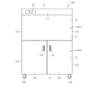
図4に本発明に係る粉砕機を示す。この粉砕機は、被粉砕物を投入する投入口122を備えた箱体160と、この箱体160に収納された粉砕機本体K(図2参照)とを備える。箱体160は、粉砕機本体Kが収納される上部収納部160aと、粉砕物収納部を構成する下部収納部160bとを備える。上部収納部160aは、前壁11と、後壁12と、左右壁13a、13bと、上壁14とを備え、上端コーナ部に傾斜壁15が設けられ、この傾斜壁15に投入口22が設けられている。なお、この傾斜壁15には図示省略したが、この粉砕機の操作を行う各種のスイッチ類が配置される。被粉砕物とは、紙類、カセットテープなどの磁気テープ式記録媒体、光学式記録媒体、基板類等の種々の製品である。   FIG. 4 shows a pulverizer according to the present invention. The pulverizer includes a box body 160 having an input port 122 through which an object to be crushed is charged, and a pulverizer body K (see FIG. 2) housed in the box body 160. The box 160 includes an upper storage portion 160a in which the pulverizer body K is stored, and a lower storage portion 160b that constitutes the pulverized material storage portion. The upper storage portion 160a includes a front wall 11, a rear wall 12, left and right walls 13a and 13b, and an upper wall 14, and an inclined wall 15 is provided at an upper end corner portion. Is provided. Although not shown in the drawings, the inclined wall 15 is provided with various switches for operating the crusher. The material to be crushed includes various products such as papers, magnetic tape recording media such as cassette tapes, optical recording media, and substrates.

下部収納部160bは、前面扉16a、16bと、後壁17と、左右壁18a、18bと、底壁19とを備える。各前面扉16a、16bには取っ手105,105が付設され、各前面扉16a、16bを揺動させることによって、下部収納部160bを開閉させることができる。この下部収納部160bに、後述する粉砕物収納部を構成する収納ケースが収納されている。なお、底壁19にはキャスター106が付設され、粉砕機の移動を可能としている。   The lower storage portion 160 b includes front doors 16 a and 16 b, a rear wall 17, left and right walls 18 a and 18 b, and a bottom wall 19. Handles 105 and 105 are attached to the front doors 16a and 16b, respectively, and the lower storage portion 160b can be opened and closed by swinging the front doors 16a and 16b. A storage case that constitutes a pulverized material storage section described later is stored in the lower storage section 160b. A caster 106 is attached to the bottom wall 19 so that the crusher can be moved.

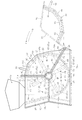
粉砕機本体Kは、図2と図3に示すように、粉砕室26を構成するケーシング21と、このケーシング21の粉砕室26に配設される粉砕手段27とを備える。ケーシング21は、ケーシング本体31と、このケーシング本体31の開口部(側方開口部)40を塞ぐ蓋部材32とを備える。また、ケーシング本体31内の上壁31aには、被粉砕物投入用のホッパ33が付設され、このホッパ33に、投入路構成体110(図1参照)が収容されている。   As shown in FIGS. 2 and 3, the pulverizer body K includes a casing 21 that constitutes a pulverization chamber 26, and pulverizing means 27 that is disposed in the pulverization chamber 26 of the casing 21. The casing 21 includes a casing main body 31 and a lid member 32 that closes an opening (side opening) 40 of the casing main body 31. Further, a hopper 33 for charging the material to be crushed is attached to the upper wall 31 a in the casing body 31, and the charging path structure 110 (see FIG. 1) is accommodated in the hopper 33.

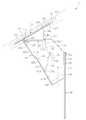
投入路構成体110は、図1と図5に示すように、矩形貫孔111が形成された鍔部112と、鍔部112から垂下される前壁113と、鍔部112から垂下される後壁114と、鍔部112から垂下される左右の側壁115a、115bと、側壁115a、115bの後方上下方向中間部を連結する連結壁116とを備える。   As shown in FIGS. 1 and 5, the charging path structure 110 includes a flange portion 112 in which a rectangular through-hole 111 is formed, a front wall 113 depending from the flange portion 112, and a rear portion depending on the flange portion 112. It includes a wall 114, left and right side walls 115a and 115b depending from the flange portion 112, and a connecting wall 116 that connects intermediate portions in the rear vertical direction of the side walls 115a and 115b.

ホッパ33は、箱体160の傾斜壁15に対向する傾斜状の上壁33aを有し、この上壁33aに、前記投入路構成体110が挿入される挿入孔117が設けられている。この場合、投入路構成体110の鍔部112が上壁33aに係止することになり、この係止状態で図示省略のボルト部材等の固着具にて投入路構成体110の鍔部112とホッパ33の上壁33aに固定する。なお、鍔部112の上面には、矩形リング状の弾性材からなるクッション材118が配置され、このクッション材118が箱体160の傾斜壁15の内面に当接している。   The hopper 33 has an inclined upper wall 33a opposite to the inclined wall 15 of the box 160, and an insertion hole 117 into which the input path constituting body 110 is inserted is provided in the upper wall 33a. In this case, the flange portion 112 of the input path structure 110 is locked to the upper wall 33a, and in this locked state, the hook portion 112 of the input path structure 110 is fixed with a fastener such as a bolt member (not shown). Fix to the upper wall 33a of the hopper 33. A cushion material 118 made of a rectangular ring-shaped elastic material is disposed on the upper surface of the collar portion 112, and the cushion material 118 is in contact with the inner surface of the inclined wall 15 of the box body 160.

また、投入路構成体110の前壁113は、上部材113aと下部材113bとを備え、下部材113bが奥側に配置されて、上部材113aと下部材113bとの間に段差部113cが設けられている。投入路構成体110の後壁114は、鍔部112の矩形貫孔111の後辺から垂下される第1壁114aと、この第1壁114aの下端から後方側に直角に折れ曲がる第2壁114bと、この第2壁114bから下方に直角に折れ曲がる第3壁114cと、この第3壁114cの下端から前壁113と略平行となるように折れ曲がる第4壁114dとを備える。   Further, the front wall 113 of the charging path structure 110 includes an upper member 113a and a lower member 113b, the lower member 113b is disposed on the back side, and a step 113c is provided between the upper member 113a and the lower member 113b. Is provided. The rear wall 114 of the charging path structure 110 includes a first wall 114a that hangs down from the rear side of the rectangular through hole 111 of the flange 112, and a second wall 114b that is bent at a right angle from the lower end of the first wall 114a to the rear side. And a third wall 114c that is bent at a right angle downward from the second wall 114b, and a fourth wall 114d that is bent so as to be substantially parallel to the front wall 113 from the lower end of the third wall 114c.

このため、前壁113と後壁114と左右の側壁115a、115bとで投入路120が構成される。また、箱体160の傾斜壁15の設けられる矩形状の開口部121と、投入路構成体110の鍔部112の矩形貫孔111と、クッション材118の矩形貫孔118a等で、投入路120の投入口122を構成することになる。   For this reason, the input path 120 is comprised by the front wall 113, the rear wall 114, and the left and right side walls 115a and 115b. Further, the input path 120 includes a rectangular opening 121 provided with the inclined wall 15 of the box 160, a rectangular through hole 111 of the flange 112 of the input path structure 110, a rectangular through hole 118 a of the cushion material 118, and the like. The charging port 122 is configured.

投入路120の投入口122は投入口蓋部材125にて塞がれる。すなわち、投入口蓋部材125は、その基端縁(投入口122の前辺側の長辺)125aが枢軸124を介して枢着される矩形状の平板体からなり、弾性部材127の弾性力にて図5(a)の矢印E方向に押圧され、その先端縁(反枢軸側の長辺部)125bが後壁114の第2壁114bに内方から当接する。これによって、投入口122が閉状態となる。この閉状態から図5(b)の矢印F方向の外力(弾性部材127の弾性力よりも大きい外力)を投入口蓋部材125に付与すれば、投入口蓋部材125は、枢軸124を中心に矢印F方向に揺動して、投入口122が開状態となる。   The input port 122 of the input channel 120 is closed by the input port lid member 125. That is, the insertion port lid member 125 is formed of a rectangular flat plate whose base end edge (long side on the front side of the insertion port 122) 125 a is pivotally attached via the pivot 124, and the elastic force of the elastic member 127 is reduced. Then, the tip edge (long side portion on the side opposite to the pivot axis) 125b abuts against the second wall 114b of the rear wall 114 from the inside. As a result, the charging port 122 is closed. If an external force in the direction of arrow F in FIG. 5B (an external force larger than the elastic force of the elastic member 127) is applied to the charging port lid member 125 from this closed state, the charging port lid member 125 is centered on the pivot 124. Oscillates in the direction, and the inlet 122 is opened.

ところで、投入口蓋部材125が水平に配置された状態で投入口122が閉状態となる。このため、前壁113は鉛直方向に対して所定角度で傾斜することになって、投入路120が斜め方向に傾斜している。   By the way, the charging port 122 is closed in a state where the charging port lid member 125 is horizontally disposed. For this reason, the front wall 113 is inclined at a predetermined angle with respect to the vertical direction, and the charging path 120 is inclined in the oblique direction.

投入路120の内部には、内部蓋部材128と、この内部蓋部材128よりも奥側(下方)の奥部蓋部材129とが配置されている。内部蓋部材128は、上端縁部130aが投入路内で枢結されて投入路閉状態と投入路開状態との変位が可能な平板状の本体板130と、この本体板130を投入路閉状態とする錘部131とを備える。   An inner lid member 128 and a rear lid member 129 on the back side (downward) than the inner lid member 128 are disposed inside the charging path 120. The inner lid member 128 has a plate-shaped main body plate 130 whose upper edge 130a is pivoted in the input path so as to be displaceable between the input path closed state and the input path open state, and the main body plate 130 is closed. And a weight portion 131 to be in a state.

すなわち、その本体板130は、側壁115a,115bに横架されて後壁114の下端縁近傍に配設される軸部材132にその上端縁部130aが固着されて、軸部材132の軸心を中心に図5(a)に示すように、矢印G、H方向に揺動可能とされる。また、錘部131は、断面矩形状の肉厚の板部材からなり、その上端縁が軸部材132に固着される。この場合、本体板130と錘部131とが側面視において、所定角度(例えば、45°程度)を成すように配置されている。   That is, the main body plate 130 is horizontally mounted on the side walls 115 a and 115 b and the upper end edge portion 130 a is fixed to the shaft member 132 disposed in the vicinity of the lower end edge of the rear wall 114. As shown in FIG. 5A at the center, it can swing in the directions of arrows G and H. The weight portion 131 is made of a thick plate member having a rectangular cross section, and the upper end edge thereof is fixed to the shaft member 132. In this case, the main body plate 130 and the weight portion 131 are arranged so as to form a predetermined angle (for example, about 45 °) in a side view.

このため、本体板130と錘部131とがバランスして、本体板130の下端縁130b(下方の長辺)が前壁113の下部材113bの内面に当接した状態となる。このため、投入路120が閉状態となる。また、この閉状態において、本体板130を下方への押圧力を付与すれば、図5(c)に示すように、本体板130は軸部材132の軸心に矢印H方向に揺動して、投入路120が開状態となる。   For this reason, the main body plate 130 and the weight portion 131 are balanced, and the lower end edge 130b (lower long side) of the main body plate 130 is in contact with the inner surface of the lower member 113b of the front wall 113. For this reason, the charging path 120 is closed. Further, in this closed state, if a downward pressing force is applied to the main body plate 130, the main body plate 130 swings in the direction of arrow H about the shaft center of the shaft member 132 as shown in FIG. The charging path 120 is opened.

奥部蓋部材129は、上端縁部135aが投入路120内で枢結された揺動板135にて構成される。すなわち、内部蓋部材128の軸部材132よりも奥側において側壁115a,115bに横架された軸部材133に上端縁部135aが固着される。このため、自由状態では、奥部蓋部材129は鉛直方向に沿って配置されて、矢印I、J方向に軸部材133の軸心を中心に揺動する。   The back cover member 129 is configured by a swing plate 135 having an upper end edge portion 135a pivoted in the input path 120. That is, the upper end edge portion 135a is fixed to the shaft member 133 that is horizontally mounted on the side walls 115a and 115b on the back side of the shaft member 132 of the inner lid member 128. For this reason, in the free state, the back cover member 129 is disposed along the vertical direction and swings about the axis of the shaft member 133 in the directions of arrows I and J.

ところで、後述するように、粉砕室26は投入路120の延長線上に開口している。このため、奥部蓋部材129が鉛直状態を維持している自由状態では、粉砕室26から飛散してくる粉砕物が投入路内へ侵入するのを防止できる。しかも、奥部蓋部材129は鉛直方向に沿って配置されて、矢印I、J方向に軸部材133の軸心を中心に揺動するので、投入口122から投入された被粉砕物が、この奥部蓋部材129に達すれば、奥部蓋部材129を奥側へ押圧することができ、この被粉砕物の通過を許容する。   By the way, as will be described later, the crushing chamber 26 opens on an extension line of the charging path 120. For this reason, in the free state in which the back cover member 129 maintains the vertical state, it is possible to prevent the pulverized material scattered from the pulverization chamber 26 from entering the input path. Moreover, the back cover member 129 is arranged along the vertical direction and swings around the axis of the shaft member 133 in the directions of arrows I and J, so that the object to be crushed charged from the charging port 122 is When the depth lid member 129 is reached, the depth lid member 129 can be pressed to the back side, and the passage of the object to be crushed is allowed.

また、投入路構成体110を箱体160に収容した場合、図1に示すように、連結壁116が鉛直方向に沿って配置されることになる。このような連結壁116に、ゴムや樹脂等の可撓性の材質からなる邪魔板98を付設している。すなわち、邪魔板98は矩形平板体からなり、その上辺部98aが連結壁116と押さえ板137とで挟持され、図示省略のボルト部材等の固着具を介してこの連結壁116に取り付けられる。このため、邪魔板98は鉛直方向に沿って配置されることになる。   Moreover, when the charging path structure 110 is accommodated in the box 160, as shown in FIG. 1, the connection wall 116 will be arrange | positioned along a perpendicular direction. A baffle plate 98 made of a flexible material such as rubber or resin is attached to the connecting wall 116. That is, the baffle plate 98 is formed of a rectangular flat plate body, and the upper side portion 98a is sandwiched between the connection wall 116 and the pressing plate 137, and is attached to the connection wall 116 via a fastener such as a bolt member (not shown). For this reason, the baffle plate 98 is arrange | positioned along a perpendicular direction.

ところで、粉砕室26は、図2に示すように、粉砕手段27が配置される本体室26aと、投入路120の下部(下流部)に連通される案内路20を備える。この案内路20の案内面20aが前記投入路120の前壁113に連続して形成され、ほぼ同一の傾斜角度で傾斜している。すなわち、投入路120からの被粉砕物が案内面20aに沿って本体室26aに案内される。この場合、邪魔板98は図2に示すように、粉砕室26の案内路20において垂下され、粉砕室26内部から飛散してくる粉砕物が投入路内へ侵入するのを防止できる。   By the way, as shown in FIG. 2, the crushing chamber 26 includes a main body chamber 26 a in which the crushing means 27 is disposed, and a guide path 20 that communicates with a lower portion (downstream portion) of the charging path 120. A guide surface 20a of the guide path 20 is continuously formed on the front wall 113 of the charging path 120 and is inclined at substantially the same inclination angle. That is, the material to be crushed from the charging path 120 is guided to the main body chamber 26a along the guide surface 20a. In this case, as shown in FIG. 2, the baffle plate 98 is suspended in the guide path 20 of the crushing chamber 26 and can prevent the crushed material scattered from the inside of the crushing chamber 26 from entering the charging path.

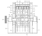
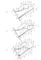
図2と図3に示すように、粉砕手段27は、回転軸45と、この回転軸45から径方向に突出するハンマー部材29と、ケーシング21内に前記ハンマー部材29の外径側に配設される固定刃47とを備える。すなわち、図3に示すように、回転軸45にはその長手方向に沿って所定ピッチに配置される円板48が設けられるとともに、円板48間にスペーサ49が介在され、この円板48とスペーサ49とで各ハンマー部材29が挟まれた状態で、ボルト・ナット結合にて回転軸45とハンマー部材29とが一体化される。   As shown in FIGS. 2 and 3, the crushing means 27 is provided with a rotating shaft 45, a hammer member 29 protruding radially from the rotating shaft 45, and an outer diameter side of the hammer member 29 in the casing 21. The fixed blade 47 is provided. That is, as shown in FIG. 3, the rotating shaft 45 is provided with discs 48 arranged at a predetermined pitch along the longitudinal direction thereof, and a spacer 49 is interposed between the discs 48. In a state where each hammer member 29 is sandwiched between the spacers 49, the rotary shaft 45 and the hammer member 29 are integrated by bolt / nut coupling.

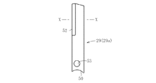
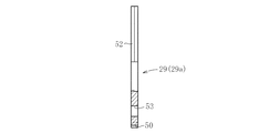
この場合、ハンマー部材29(第1ハンマー部材29a)は、図6から図8に示すように、基端縁に凹部50が形成された断面扁平矩形の棒状体からなり、その一方の長辺の先端側に刃部(粉砕刃)52が形成されている。また、凹部50の近傍には貫通孔53が設けられている。   In this case, as shown in FIGS. 6 to 8, the hammer member 29 (first hammer member 29a) is composed of a rod-like body having a flat rectangular cross section with a recess 50 formed at the base end edge, and has one long side. A blade portion (grinding blade) 52 is formed on the tip side. A through hole 53 is provided in the vicinity of the recess 50.

そして、各円板48に貫孔(図示省略)が設けられ、図3に示すように、円板48とスペーサ49とで各第1ハンマー部材29(29a)が挟まれた状態で、円板48に貫孔、ハンマー部材29の貫通孔53、及びスペーサ49に、一方の外側の円板48の外方から図示省略のボルト部材を挿通し、他方の外側の円板48から外方へ突出したボルト部材のねじ端部にナット部材55(図2参照)を螺着することになる。この際、ハンマー部材29aの凹部50が回転軸45の外周面に嵌合している。   Each disc 48 is provided with a through hole (not shown). As shown in FIG. 3, the disc 48 and the spacer 49 sandwich each first hammer member 29 (29a), and the disc A bolt member (not shown) is inserted into the through hole 48, the through hole 53 of the hammer member 29, and the spacer 49 from the outside of one outer disk 48, and protrudes outward from the other outer disk 48. The nut member 55 (see FIG. 2) is screwed onto the screw end portion of the bolt member. At this time, the recess 50 of the hammer member 29 a is fitted to the outer peripheral surface of the rotating shaft 45.

図3に示すように、回転軸45の軸方向に沿って4個のハンマー部材29(29a)を配置することによって、ハンマー部材集合体を構成し、図2に示すように、このハンマー部材集合体を周方向に沿って90度ピッチで4個配置されている。   As shown in FIG. 3, four hammer members 29 (29a) are arranged along the axial direction of the rotary shaft 45 to constitute a hammer member assembly. As shown in FIG. Four bodies are arranged at a pitch of 90 degrees along the circumferential direction.

また、ケーシング21の両面側には、支持脚56、57が配置され、この支持脚56、57に軸受部材58、59を介して回転自在に回転軸45の端部が支持されている。そして、回転軸45の一方の端部が、ベルト部材を有する連動機構60を介して図示省略の駆動用モータの出力軸に連結されている。このため、駆動用モータが駆動することによって、この駆動用モータの駆動力が連動機構60を介して回転軸45に伝達されて回転する。   Support legs 56 and 57 are disposed on both sides of the casing 21, and end portions of the rotating shaft 45 are supported by the support legs 56 and 57 via bearing members 58 and 59 so as to be rotatable. One end of the rotating shaft 45 is connected to an output shaft of a driving motor (not shown) via an interlocking mechanism 60 having a belt member. For this reason, when the driving motor is driven, the driving force of the driving motor is transmitted to the rotating shaft 45 via the interlocking mechanism 60 to rotate.

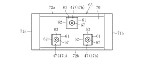
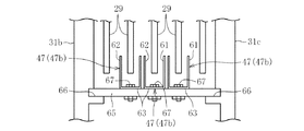
ところで、各固定刃47は、図3に示すように、第1刃61と、第2刃62と、第1刃61と第2刃62とを連結する連結片部63とからなるコの字状体にて構成され、複数の固定刃47が平板状保持用プレート64および円弧状保持用プレート65(図9と図10参照)に固着される。この場合、平板状保持用プレート64はケーシング21の上壁31aの下面に固着される。また、平板状保持用プレート64に固着される各固定刃47(47a)は、連結片部63および平板状保持用プレート64に挿通されるボルト部材67がケーシング21の上壁31aに螺合される。この際、この平板状保持用プレート64に固着された複数の固定刃47は、下方、つまり粉砕室26に突出する。なお、上壁31a側の第1刃61と第2刃62は、図2に示すようにその刃先28が開口部40側を向いている。   By the way, as shown in FIG. 3, each fixed blade 47 has a U-shape comprising a first blade 61, a second blade 62, and a connecting piece portion 63 that connects the first blade 61 and the second blade 62. A plurality of fixed blades 47 are fixed to a flat plate-shaped holding plate 64 and an arc-shaped holding plate 65 (see FIGS. 9 and 10). In this case, the flat holding plate 64 is fixed to the lower surface of the upper wall 31a of the casing 21. Further, each fixed blade 47 (47a) fixed to the flat plate holding plate 64 has a connecting piece 63 and a bolt member 67 inserted into the flat plate holding plate 64 screwed into the upper wall 31a of the casing 21. The At this time, the plurality of fixed blades 47 fixed to the flat plate-like holding plate 64 protrude downward, that is, into the crushing chamber 26. The first blade 61 and the second blade 62 on the upper wall 31a side have the cutting edge 28 facing the opening 40 as shown in FIG.

また、ハンマー部材29(29a)は、前記したように回転軸45の軸心廻りに回転するので、ハンマー部材29の先端縁は回転時に円軌跡を描くことになる。そこで、前記円弧状保持用プレート65は、この円軌跡に沿った(対向)した曲率半径となる円弧形状からなる。そして、ケーシング21には、この円軌跡の外径側にこの円軌跡に沿ったプレート嵌合溝66(図15参照)が形成され、このプレート嵌合溝66に円弧状保持用プレート65が嵌合される。なお、プレート嵌合溝66は、前壁31bと後壁31cとにそれぞれ形成される円弧溝からなる。   Further, as described above, the hammer member 29 (29a) rotates around the axis of the rotary shaft 45, so that the tip edge of the hammer member 29 draws a circular locus during rotation. Therefore, the arc-shaped holding plate 65 has an arc shape having a radius of curvature along (opposed to) this circular locus. The casing 21 is formed with a plate fitting groove 66 (see FIG. 15) along the circular locus on the outer diameter side of the circular locus, and the arc-shaped holding plate 65 is fitted into the plate fitting groove 66. Combined. The plate fitting groove 66 is a circular groove formed in each of the front wall 31b and the rear wall 31c.

円弧状保持用プレート65に取り付けられる固定刃47(47b)も、その各連結片部
63がボルト部材67を介してこの円弧状保持用プレート65に固着される。なお、円弧状保持用プレート65は、図9と図10に示すように、基板部70と、この基板部70の内面(固定刃47が突出する側の面)の両短辺側に配置される短辺枠71a、71bと、基板部70の内面の両長辺側に配置される長辺枠72a、72bとからなる。そして、一方の長辺枠72a側に1個の固定刃47bが配置され、他方の長辺枠72b側に2個の固定刃47bが配置されている。
The fixed blades 47 (47 b) attached to the arc-shaped holding plate 65 are also fixed to the arc-shaped holding plate 65 through the bolt members 67. As shown in FIGS. 9 and 10, the arc-shaped holding plate 65 is disposed on both short sides of the substrate portion 70 and the inner surface of the substrate portion 70 (the surface on the side from which the fixed blade 47 protrudes). Short side frames 71a and 71b, and long side frames 72a and 72b arranged on both long sides of the inner surface of the substrate portion 70. One fixed blade 47b is arranged on one long side frame 72a side, and two fixed blades 47b are arranged on the other long side frame 72b side.

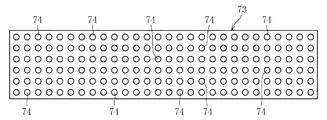
この場合、円弧状保持用プレート65を一対備え、円弧状保持用プレート65間に図11と図12に示すような排出用プレート73が配置される。このため、排出用プレート73はハンマー部材29の先端縁の円軌跡に対応する円弧状体とされ、多数の排出孔(パン
チ孔)74が設けられている。そして、排出用プレート73はプレート嵌合溝66に嵌合されて回転軸45の下方に配置される。すなわち、円弧状保持用プレート65間において下部排出口23は形成され、この下部排出口23に排出用プレート73が配置されている。
In this case, a pair of arc-shaped holding plates 65 are provided, and a discharge plate 73 as shown in FIGS. 11 and 12 is arranged between the arc-shaped holding plates 65. Therefore, the discharge plate 73 has an arc shape corresponding to the circular locus of the tip edge of the hammer member 29 and is provided with a number of discharge holes (punch holes) 74. The discharge plate 73 is fitted in the plate fitting groove 66 and is disposed below the rotary shaft 45. That is, the lower discharge port 23 is formed between the arc-shaped holding plates 65, and the discharge plate 73 is disposed in the lower discharge port 23.

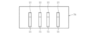
ところで、案内路20の下流側(下部側)には、図2に示すように、被粉砕物を粉砕室26側へ浮き上がらせるガイド体75が配置されている。このガイド体75は、図11と図12に示すように、円弧状保持用プレート76に一体的に固着されている。この場合も、円弧状保持用プレート76は、固定刃47を保持する円弧状保持用プレート65と同様、ハンマー部材29の先端縁の円軌跡に沿った(対向)した曲率半径となる円弧形状からなる。   By the way, as shown in FIG. 2, a guide body 75 is disposed on the downstream side (lower side) of the guide path 20 to lift the object to be crushed toward the pulverization chamber 26. As shown in FIGS. 11 and 12, the guide body 75 is integrally fixed to the arc-shaped holding plate 76. Also in this case, the arc-shaped holding plate 76 has an arc shape having a radius of curvature along (opposed to) the circular locus of the tip edge of the hammer member 29, like the arc-shaped holding plate 65 that holds the fixed blade 47. Become.

また、ガイド体75はそのプレートの幅方向に延びるブロック片からなり、その上端縁には、傾斜面77が形成されている。ガイド体75は円弧状保持用プレート76に長手方向に沿って所定ピッチで4個配設されている。そして、この円弧状保持用プレート76が前記プレート嵌合溝66に嵌合されることによって、ガイド体75が案内路20の下流側(下部側)に配置される。   Moreover, the guide body 75 consists of the block piece extended in the width direction of the plate, and the inclined surface 77 is formed in the upper end edge. Four guide bodies 75 are arranged on the arc-shaped holding plate 76 at a predetermined pitch along the longitudinal direction. The guide body 75 is arranged on the downstream side (lower side) of the guide path 20 by fitting the arc-shaped holding plate 76 into the plate fitting groove 66.

この場合、案内路20の下流側から開口部40に向かって、ガイド体75、固定刃47b、排出用プレート73、固定刃47bと順次配置されている。そして、ハンマー部材29の回転時には、各ハンマー部材29の刃部52は、ガイド体75の間を通過するとともに、上壁31a側の固定刃47aの第1刃61と第2刃との間を通過する。また、プレート嵌合溝66側においては、内側の3本のハンマー部材29の刃部52が固定刃47bの第1刃61と第2刃との間を通過し、外側の2本のハンマー部材29の刃部52が外側の固定刃47bの外側を通過する。なお、一対の円弧状保持用プレート65が配置された状態では、各固定刃47bはその刃先68がガイド体75側を向く。   In this case, the guide body 75, the fixed blade 47b, the discharge plate 73, and the fixed blade 47b are sequentially arranged from the downstream side of the guide path 20 toward the opening 40. During rotation of the hammer member 29, the blade portion 52 of each hammer member 29 passes between the guide bodies 75 and between the first blade 61 and the second blade of the fixed blade 47a on the upper wall 31a side. pass. On the plate fitting groove 66 side, the blade portions 52 of the three inner hammer members 29 pass between the first blade 61 and the second blade of the fixed blade 47b, and the two outer hammer members. 29 blade portions 52 pass outside the outer fixed blade 47b. Note that in the state where the pair of arc-shaped holding plates 65 are arranged, the blade edges 68 of the fixed blades 47b face the guide body 75 side.

ところで、開口部40は正面視において約120度をなし、前壁31bの縦方向開口端及び斜め方向開口端にそれぞれ鍔部80、81が設けられ、後壁31cの縦方向開口端及び斜め方向開口端にそれぞれ鍔部82、83が設けられている。なお、前壁31bの上下方向中間部、及び反開口端部にはリブ84、85が設けられている。   By the way, the opening 40 forms approximately 120 degrees in a front view, and flanges 80 and 81 are provided at the longitudinal opening end and the oblique opening end of the front wall 31b, respectively, and the longitudinal opening end and the oblique direction of the rear wall 31c. Reed portions 82 and 83 are provided at the open ends, respectively. It should be noted that ribs 84 and 85 are provided at the middle portion in the vertical direction of the front wall 31b and the end portion opposite to the opening.

蓋部材32は、前壁87と後壁88と周壁89とを備え、その下端部がヒンジ部90にてケーシング21の本体31に矢印C、Dのように揺動可能に枢結されている。周壁89は前方から見て、ヒンジ部90から立ち上がる第1壁89aと、第1壁89aに連設される第2壁89bと、第2壁89bに連設される第3壁89cと、第3壁89cに連設される第3壁89dとを備える。   The lid member 32 includes a front wall 87, a rear wall 88, and a peripheral wall 89, and a lower end portion of the lid member 32 is pivotally connected to the main body 31 of the casing 21 by a hinge portion 90 as indicated by arrows C and D. . The peripheral wall 89 is seen from the front, the first wall 89a rising from the hinge portion 90, the second wall 89b connected to the first wall 89a, the third wall 89c connected to the second wall 89b, A third wall 89d connected to the third wall 89c.

このように、前壁87は扇形状であって、ケーシング21の前壁31bの縦方向開口端面に対応する第1端面、ケーシング21の前壁31bの斜め方向開口端に対応する第2端
面にはそれぞれ鍔部91,92が設けられている。後壁88も扇形状であって、ケーシング21の後壁31cの縦方向開口端面に対応する第1端面、ケーシング21の後壁31cの斜め方向開口端に対応する第2端面にはそれぞれ鍔部(図示省略)が設けられている。
As described above, the front wall 87 has a fan shape, and has a first end surface corresponding to the longitudinal opening end surface of the front wall 31b of the casing 21 and a second end surface corresponding to the oblique opening end of the front wall 31b of the casing 21. Are provided with flanges 91 and 92, respectively. The rear wall 88 is also fan-shaped, and the first end surface corresponding to the longitudinally open end surface of the rear wall 31c of the casing 21 and the second end surface corresponding to the obliquely open end of the rear wall 31c of the casing 21 (Not shown) is provided.

このため、図2の実線で示すように、蓋部材32を、前壁87の鍔部91、92をケーシング21の前壁31bの鍔部80、81に当接させることができるとともに、後壁88の鍔部をケーシング21の後壁31cの鍔部82、83に当接させることができる。   Therefore, as shown by the solid line in FIG. 2, the lid member 32 can bring the flange portions 91 and 92 of the front wall 87 into contact with the flange portions 80 and 81 of the front wall 31 b of the casing 21 and the rear wall. The 88 flanges can be brought into contact with the flanges 82 and 83 of the rear wall 31 c of the casing 21.

このように、当接させた状態が蓋部材32による閉状態となる。そして、この閉状態では、プレート嵌合溝66の開口部40側の開口端が塞がれ、このプレート嵌合溝66に嵌合している各プレート65,73、76の開口部側への抜けが防止される。また、各プレート65,73、76の反開口部側への抜けは、プレート嵌合溝66の反開口部端によって規制される。このため、蓋部材32による閉状態で、各プレート65,73、76を定位置に固定することができる。   In this way, the abutted state is a closed state by the lid member 32. In this closed state, the opening end of the plate fitting groove 66 on the opening 40 side is closed, and the plates 65, 73, 76 fitted in the plate fitting groove 66 are opened to the opening side. Omission is prevented. Further, the withdrawal of each of the plates 65, 73, 76 to the opposite opening side is restricted by the opposite opening end of the plate fitting groove 66. For this reason, each plate 65, 73, 76 can be fixed at a fixed position in the closed state by the lid member 32.

また、蓋部材32の周壁89の内面には、複数の粉砕補助用凸部95が設けられている。ここで、粉砕補助用凸部95とは、断面正方形乃至矩形状の水平方向に延びるバーであり、周壁89の内面に所定ピッチで周壁89に沿って配置されている。なお、蓋部材32には開閉操作を行うための取手99が設けられている。   A plurality of crushing assisting convex portions 95 are provided on the inner surface of the peripheral wall 89 of the lid member 32. Here, the crushing assisting convex portion 95 is a bar having a square or rectangular cross section and extending in the horizontal direction, and is disposed on the inner surface of the peripheral wall 89 along the peripheral wall 89 at a predetermined pitch. The lid member 32 is provided with a handle 99 for performing an opening / closing operation.

次に前記のように構成した粉砕機を使用した粉砕方法を説明する。図1や図5(a)に示すように、投入口122が投入口蓋部材125にて塞がれている状態であるので、被粉砕物にて投入口蓋部材125を内方へ押圧するか、または使用者が投入口蓋部材125を内方へ押圧するかして、投入口122を図5(b)等に示すように開状態とする。これによって、投入口122から被粉砕物を投入路120に投入する。この状態では、内部蓋部材128にて投入路120が閉状態となっている。このため、粉砕室26の粉砕物がこの投入路120に侵入したとしても、この内部蓋部材128にて投入口122側への飛散を防止できる。   Next, a pulverization method using the pulverizer configured as described above will be described. As shown in FIG. 1 and FIG. 5 (a), since the charging port 122 is closed by the charging port lid member 125, the charging port lid member 125 is pressed inward with the material to be crushed, Alternatively, the user presses the input port lid member 125 inward to open the input port 122 as shown in FIG. As a result, the material to be crushed is input to the input path 120 from the input port 122. In this state, the charging path 120 is closed by the inner lid member 128. For this reason, even if the pulverized material in the crushing chamber 26 enters the charging path 120, the inner lid member 128 can prevent scattering toward the charging port 122.

また、被粉砕物が内部蓋部材128に到達すれば、被粉砕物にて内部蓋部材128が下方へ押圧されて、図5(c)の矢印H方向に揺動して、被粉砕物の通過を許容する。内部蓋部材128を被粉砕物が通過する際には、被粉砕物は投入口122を通過しており、投入口蓋部材125が弾性部材127の弾性力にて図5(a)に示すように閉状態に戻る。このため、内部蓋部材128が開状態となっても、投入口蓋部材125が閉状態に戻っているので、投入口122から粉砕物が飛び出ることがない。   Further, when the object to be crushed reaches the inner lid member 128, the inner lid member 128 is pressed downward by the object to be crushed and swings in the direction of arrow H in FIG. Allow passage. When the object to be crushed passes through the inner lid member 128, the object to be crushed has passed through the charging port 122, and the charging port lid member 125 is caused by the elastic force of the elastic member 127 as shown in FIG. Return to the closed state. For this reason, even if the inner lid member 128 is in the open state, the charging port lid member 125 has returned to the closed state, so that the crushed material does not jump out of the charging port 122.

そして、被粉砕物が内部蓋部材128を通過して、奥部蓋部材129に差し掛かれば、奥部蓋部材129は揺動自在であるので、この被粉砕物に押されてこの奥部蓋部材129における被粉砕物の通過を許容する。その後は、案内路20に案内されて粉砕室26の本体室26aに供給される。この際、回転軸45を回転させてハンマー部材29を図2の矢印A方向に回転させておく。   Then, if the object to be crushed passes through the inner lid member 128 and reaches the inner lid member 129, the inner lid member 129 can swing, so that it is pushed by the object to be crushed and this inner lid member 129 is pushed. The material to be ground in the member 129 is allowed to pass. After that, it is guided by the guide path 20 and supplied to the main body chamber 26 a of the crushing chamber 26. At this time, the rotary shaft 45 is rotated to rotate the hammer member 29 in the direction of arrow A in FIG.

被粉砕物が本体室26aの入口部に設けられたガイド体75によって、被粉砕物は粉砕室26側へ浮き上がる。すなわち、案内傾斜面20aに沿って下降してきた被粉砕物が、このガイド体75を傾斜面77にガイドされて、案内傾斜面20aから浮き上がる。このため、回転しているハンマー部材29にて、被粉砕物を打撃しかつ刃先で切断する。そして、切断片をハンマー部材29が巻き込んで、下部排出口側の固定刃47bと、上壁31a側の固定刃47aとで、切断片をさらに細かく切断し、解すなどの処理を行う。このこのように、ガイド体75を設けることによって、被粉砕物を浮き上げることができるので、被粉砕物がシート状のものである場合、被粉砕物が壁面に付着することを防止して、ハンマー部材29による粉砕を可能とできる。   The object to be pulverized is lifted to the pulverizing chamber 26 side by the guide body 75 provided at the entrance of the main body chamber 26a. That is, the object to be crushed that has descended along the inclined guide surface 20a is guided by the inclined surface 77 through the guide body 75 and floats up from the inclined guide surface 20a. For this reason, the object to be crushed is hit with a rotating hammer member 29 and cut with a cutting edge. Then, the hammer member 29 is wound around the cut piece, and the cut piece is further finely cut and unwound by the fixed blade 47b on the lower discharge port side and the fixed blade 47a on the upper wall 31a side. In this way, by providing the guide body 75, the object to be crushed can be lifted, so that when the object to be pulverized is a sheet, the object to be crushed is prevented from adhering to the wall surface, The hammer member 29 can be crushed.

また、ハンマー部材29の先端縁が蓋部材32の粉砕補助用凸部95の近傍を通過し、このハンマー部材29の先端縁と粉砕補助用凸部95とで切断片が擦りつぶされ、粉砕物となる。粉砕物は下部排出口23に設けられた排出用プレート73の排出孔74から、このケーシング21の下部、つまり箱体160の下部収納部160bに配置された収納ケース(図示省略)に排出される。   Further, the tip edge of the hammer member 29 passes in the vicinity of the crushing assisting convex portion 95 of the lid member 32, and the cutting piece is crushed by the tip edge of the hammer member 29 and the crushing assisting convex portion 95, and the pulverized product. It becomes. The pulverized material is discharged from a discharge hole 74 of a discharge plate 73 provided in the lower discharge port 23 to a storage case (not shown) disposed in the lower portion of the casing 21, that is, in the lower storage portion 160 b of the box 160. .

ところで、被粉砕物が粉砕室26に進入する際に、回転しているハンマー部材29に被粉砕物がかみ込むことになって、ハンマー部材29にて被粉砕物がはじき飛ばされにくくなる。   By the way, when the object to be crushed enters the crushing chamber 26, the object to be crushed bites into the rotating hammer member 29, so that the object to be crushed is not easily repelled by the hammer member 29.

しかしながら、邪魔板98が図2に示すように、粉砕室26の案内路20において垂下されているので、被粉砕物がたとえは弾き飛ばされても、この邪魔板98によって被粉砕物が粉砕室26に戻される。   However, since the baffle plate 98 hangs down in the guide path 20 of the crushing chamber 26 as shown in FIG. 2, even if the object to be crushed is blown off, the baffle plate 98 causes the material to be crushed to be crushed. 26 is returned.

このため、被粉砕物がカセットテープのようなプラスチックブロック体であっても、前記紙類等のシート状体のように、回転しているハンマー部材29にて、この被粉砕物を打撃しかつ刃先で切断する。そして、切断片をハンマー部材29が巻き込んで、下部排出口側の固定刃47と、上壁31a側の固定刃47とで、切断片をさらに細かく切断し、解すなどの処理を行い、さらに、ハンマー部材29の先端縁と粉砕補助用凸部95とで切断片を擦りつぶし、粉砕物となる。   Therefore, even if the object to be crushed is a plastic block such as a cassette tape, the object to be crushed is hit with a rotating hammer member 29 like a sheet-like object such as paper. Cut with a cutting edge. Then, the hammer member 29 is wound around the cut piece, and the cut piece is further finely cut and unwound with the fixed blade 47 on the lower discharge port side and the fixed blade 47 on the upper wall 31a side, The cutting piece is crushed by the tip edge of the hammer member 29 and the pulverization assisting convex portion 95 to form a pulverized product.

本発明では、自由状態では投入口122は投入口蓋部材125にて塞がれている。この状態で、弾性部材127の弾性力に抗して投入口蓋部材125を押圧すれば、投入口122が開状態となって、被粉砕物の投入が可能となる。また、自由状態では、内部蓋部材128はその自重により投入路内部を塞いでいるが、投入口開状態で投入路120に入った被粉砕物がこの内部蓋部材128に達すれば、この被粉砕物によって押圧されて開状態となって、被粉砕物が粉砕室26に投入されることになる。   In the present invention, the inlet 122 is closed by the inlet lid member 125 in the free state. In this state, when the charging port lid member 125 is pressed against the elastic force of the elastic member 127, the charging port 122 is opened, and the material to be crushed can be charged. Further, in the free state, the inner lid member 128 blocks the inside of the charging path by its own weight. However, if the object to be crushed that has entered the charging path 120 in the opening state of the inlet reaches the inner lid member 128, The object to be crushed is opened by being pressed by the object, and the object to be crushed is put into the crushing chamber 26.

すなわち、被粉砕物の投入口120の投入状態では、投入口蓋部材125は開状態となっているが、内部蓋部材128にて投入路122が塞がれているので、粉砕室26からの粉砕物がこの投入路120を介して外部へ流出しない。また、被粉砕物が内部蓋部材128を通過する際には、投入口120においては被粉砕物が通過した後であるので、投入口蓋部材125にて投入口120が閉状態となっており、粉砕物がこの投入口120を介して外部へ流出しない。   In other words, when the charging port 120 for the object to be crushed is in the charging state, the charging port lid member 125 is in the open state, but the charging path 122 is blocked by the internal lid member 128, so Goods do not flow out to the outside through the charging path 120. In addition, when the object to be crushed passes through the inner lid member 128, since the object to be crushed has passed through the inlet 120, the inlet 120 is closed by the inlet lid member 125. The pulverized material does not flow out through the charging port 120.

このように本発明では、被粉砕物が粉砕室26に投入される際には、被粉砕物の投入が許容されるが、内部蓋部材128又は投入口蓋部材125にて投入路120が塞がれることになる。このため、粉砕室26にて粉砕されてなる粉砕物の投入口122からの流出が防止され、この粉砕機の外装および粉砕機設置室を粉砕物にて汚すことが極めて少なくなって、清潔性を維持でき、作業者は快適に作業できるとともに、清掃の容易化を図ることができる。   As described above, in the present invention, when the material to be crushed is put into the crushing chamber 26, the material to be crushed is allowed to be charged, but the charging path 120 is blocked by the internal lid member 128 or the charging port lid member 125. Will be. Therefore, the pulverized product pulverized in the pulverization chamber 26 is prevented from flowing out from the inlet 122, and the exterior of the pulverizer and the pulverizer installation chamber are hardly contaminated with the pulverized product. Thus, the operator can work comfortably and facilitate cleaning.

特に、奥部蓋部材129を設けることによって、粉砕物が内部蓋部材128を通過してこの内部蓋部材128が開状態であるときに、投入口蓋部材125が人為的に開状態とされていたとしても、奥部蓋部材129にて、粉砕物の投入路120への戻りを規制することができる。すなわち、粉砕室26側から粉砕物の飛散があれば、飛散物が奥部蓋部材129の裏面129aに当たることになる。そしてこの衝突によって押圧力が付与された場合、奥部蓋部材129は、矢印I方向に揺動することになり、図5(c)の仮想線で示すように、その下端部135bが投入路構成体110の前壁113の下端縁に当接する。これによって、投入路120はその下方において塞がれる。このため、粉砕物の投入口122を介した外部への流出防止作用の向上を図ることができる。しかも、奥部蓋部材129は被粉砕物の粉砕室26への投入を許容でき、この奥部蓋部材129によって粉砕室26への投入を邪魔されない。   In particular, by providing the back cover member 129, when the pulverized material passes through the internal cover member 128 and the internal cover member 128 is in the open state, the charging port cover member 125 has been artificially opened. However, the back cover member 129 can restrict the return of the pulverized material to the charging path 120. That is, if the pulverized material is scattered from the pulverization chamber 26 side, the scattered material hits the back surface 129a of the back cover member 129. When a pressing force is applied by this collision, the back cover member 129 swings in the direction of the arrow I, and the lower end portion 135b of the back cover member 129 is turned on as shown in the phantom line of FIG. It contacts the lower edge of the front wall 113 of the structure 110. As a result, the charging path 120 is blocked at the bottom. For this reason, it is possible to improve the effect of preventing the pulverized material from flowing out through the inlet 122. In addition, the back cover member 129 can allow the material to be crushed to be put into the crushing chamber 26, and the back cover member 129 does not disturb the charging into the crushing chamber 26.

内部蓋部材128は、その上端縁部130aが投入路内で枢結されて投入路閉状態と投入路開状態との変位が可能な平板状の本体板130と、この本体板130を投入路閉状態とする錘部131とを備えたもので構成できる。すなわち、錘部131の重さで、本体板130を投入路閉状態となるように揺動させることができ、被粉砕物が内部蓋部材128を通過すれば、この被粉砕物に押圧されて本体板130が開状態となる。   The inner lid member 128 has a plate-shaped main body plate 130 whose upper edge 130a is pivoted in the input path so as to be displaceable between the input path closed state and the input path open state, and the main body plate 130 is connected to the input path. It can comprise with the weight part 131 made into a closed state. That is, the weight of the weight portion 131 allows the main body plate 130 to be swung so as to be in the closing path, and if the object to be crushed passes through the inner lid member 128, it is pressed by the object to be crushed. The main body plate 130 is opened.

奥部蓋部材129は、上端縁部135aが投入路内で枢結された揺動板135にて構成することができる。すなわち、自由状態では、揺動板135は鉛直状態を維持でき、これによって、粉砕物の投入路120への戻りを規制することができる。また、奥部蓋部材129を被粉砕物が通過すれば、被粉砕物に押されて被粉砕物の通過を許容する。   The back cover member 129 can be configured by a swing plate 135 having an upper end edge portion 135a pivotally connected in the input path. In other words, in the free state, the swinging plate 135 can maintain the vertical state, thereby restricting the return of the pulverized material to the charging path 120. Further, if the object to be crushed passes through the back cover member 129, the object to be crushed is pushed by the object to be crushed to allow passage of the object to be crushed.

また、前記粉砕機によれば、案内路20の下流側に設けられるガイド体75にて被粉砕物が粉砕室26側に浮きあがらせることができ、ハンマー部材29に被粉砕物を接触させることができる。すなわち、被粉砕物が粉砕室26の内面に付着することがなくなって、被粉砕物を安定して粉砕することができる。   Further, according to the pulverizer, the object to be pulverized can be lifted to the pulverization chamber 26 side by the guide body 75 provided on the downstream side of the guide path 20, and the object to be pulverized is brought into contact with the hammer member 29. Can do. That is, the object to be pulverized does not adhere to the inner surface of the pulverizing chamber 26, and the object to be pulverized can be stably pulverized.

粉砕物は排出用プレート73の孔部74から外部(下方)へ排出するので、この孔部74の径よりも大きな粉砕物は排出されないで、粉砕室26に留まり、さらにハンマー部材29と固定刃47によって粉砕される。このため、孔部74の孔径以下に粉砕された粉砕物のみを外部へ排出することができる。また、固定刃47及びガイド体75はそれぞれ円弧状保持用プレート65,76に付設され、その取り扱い性に優れる。   Since the pulverized material is discharged to the outside (downward) from the hole portion 74 of the discharge plate 73, the pulverized material larger than the diameter of the hole portion 74 is not discharged and remains in the pulverization chamber 26, and further, the hammer member 29 and the fixed blade 47. For this reason, only the pulverized material pulverized to the diameter of the hole 74 or less can be discharged to the outside. Further, the fixed blade 47 and the guide body 75 are attached to the arc-shaped holding plates 65 and 76, respectively, and are excellent in handleability.

ケーシング21のプレート嵌合溝66に固定刃47及びガイド体75をそれぞれ円弧状保持用プレート65,76に装着することによって、排出用プレート73と、固定刃47及びガイド体75のプレート65,76とをケーシング21に装着することができ、固定刃47やガイド体75等のセットが容易となる。しかも、プレート65,76の装着作業をケーシング21に設けられた開口部40を介して行うことができる。開口部40を蓋部材32にて閉状態とすることによって、プレート嵌合溝66に装着された各プレート65,76を固定することができる。   By attaching the fixed blade 47 and the guide body 75 to the arc-shaped holding plates 65 and 76 in the plate fitting groove 66 of the casing 21, respectively, the discharge plate 73 and the plates 65 and 76 of the fixed blade 47 and the guide body 75 are mounted. Can be attached to the casing 21, and the fixed blade 47, the guide body 75, etc. can be easily set. Moreover, the mounting work of the plates 65 and 76 can be performed through the opening 40 provided in the casing 21. By closing the opening 40 with the lid member 32, the plates 65 and 76 mounted in the plate fitting groove 66 can be fixed.

このため、開口部40を開状態として、ケーシング21のプレート嵌合溝66に固定刃47及びガイド体75をそれぞれ円弧状保持用プレート65,76に嵌合させて、蓋部材32を閉状態とすれば、固定刃47やガイド体75等と定位置にセットすることができる。また、セットした状態から蓋部材32を開状態とすれば、各プレート65,76の固定状態が解除され、排出用プレート73と、固定刃47及びガイド体75のプレート65,76の取り出しが可能となる。   Therefore, the opening 40 is opened, the fixed blade 47 and the guide body 75 are fitted to the arc-shaped holding plates 65 and 76 in the plate fitting groove 66 of the casing 21, respectively, and the lid member 32 is closed. Then, the fixed blade 47, the guide body 75, etc. can be set at a fixed position. If the lid member 32 is opened from the set state, the fixed state of the plates 65 and 76 is released, and the discharge plate 73, the fixed blade 47, and the plates 65 and 76 of the guide body 75 can be taken out. It becomes.

したがって、固定刃47やガイド体75等のメンテナンスや取替え作業を短時間かつ確実に行うことができ、この粉砕機を長期に亘って安定した使用が可能となり、ランニングコスト低減に寄与する。   Therefore, the maintenance and replacement work of the fixed blade 47, the guide body 75, etc. can be performed in a short time and reliably, and this pulverizer can be used stably over a long period of time, which contributes to a reduction in running cost.

また、ハンマー部材29と固定刃47とで被粉砕物を粉砕するので、柔らかい帳簿などの紙類であっても、硬い基板等であっても粉砕可能であり、種々の情報(個人情報等)を記憶している記憶媒体を再生不能な状態まで粉砕できる。しかも、既存のシュレッダーで紙を粉砕した場合、紙の繊維が細かく切断されるため、リサイクル性に劣るが、本発明の粉砕機で紙を粉砕した場合、紙の繊維が比較的残り、リサイクル性に優れる。   Further, since the object to be crushed is pulverized by the hammer member 29 and the fixed blade 47, it can be pulverized by paper such as a soft book or a hard substrate. Various information (personal information, etc.) Can be crushed to a non-reproducible state. In addition, when paper is crushed with an existing shredder, the paper fibers are finely cut, so it is inferior in recyclability. However, when paper is crushed with the pulverizer of the present invention, the paper fibers remain relatively recyclable. Excellent.

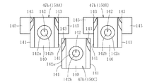
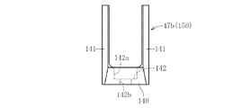
図16は円弧状保持用プレート65に付設される固定刃47b(150)の変形例である。この固定刃47bは、図17と図18に示すように、矩形状の基部140と、この基部140の両端部(長辺側端部)から立設される一対の比較的肉厚の立ち上がり壁141、141とを備える。基部140にはボルト孔142が形成されている。このボルト孔142は、大径部142aと、この大径部142aに連通される貫通孔142bとからなる。そして、このボルト孔142にボルト部材(図示省略)が挿入されてプレート65に螺着される。   FIG. 16 shows a modified example of the fixed blade 47 b (150) attached to the arc-shaped holding plate 65. As shown in FIGS. 17 and 18, the fixed blade 47 b includes a rectangular base portion 140 and a pair of relatively thick rising walls erected from both end portions (long side end portions) of the base portion 140. 141, 141. Bolt holes 142 are formed in the base 140. The bolt hole 142 includes a large diameter portion 142a and a through hole 142b communicating with the large diameter portion 142a. A bolt member (not shown) is inserted into the bolt hole 142 and screwed to the plate 65.

この場合、円弧状保持用プレート65には、上方側に2つの固定刃150A,150Bと、この固定刃150A,150Bとの間に配設される下方の固定刃150Cとを備える。立ち上がり壁141、141の側辺に刃部143、143が設けられている。この刃部143が上方を向くように配置されている。また、刃部143の刃先143aは基部140側から立上り壁141の先端側に向かって後方に傾斜するテーパとなっている。すなわち、この刃先143a(図18等参照)は、ハンマー部材9の先端縁が回転時に描く円軌跡に対応する円弧面の径方向に対して傾斜した状態となる。なお、固定刃150A,150Bの位置決めブロック145にて位置決めされている。   In this case, the arc-shaped holding plate 65 includes two fixed blades 150A and 150B on the upper side, and a lower fixed blade 150C disposed between the fixed blades 150A and 150B. Blade portions 143 and 143 are provided on the sides of the rising walls 141 and 141. The blade portion 143 is arranged so as to face upward. Further, the blade edge 143 a of the blade portion 143 has a taper that inclines backward from the base portion 140 side toward the distal end side of the rising wall 141. That is, the blade edge 143a (see FIG. 18 and the like) is in a state where the tip edge of the hammer member 9 is inclined with respect to the radial direction of the arc surface corresponding to the circular locus drawn at the time of rotation. It is positioned by the positioning block 145 of the fixed blades 150A and 150B.

このような固定刃150では剛性が大となり、しかも、刃部143の刃先143aがテーパとなっているので、安定して粉砕を可能とする。   Such a fixed blade 150 has high rigidity, and furthermore, since the blade edge 143a of the blade portion 143 is tapered, it can be stably pulverized.

なお、平板状保持用プレート64に固着される固定刃47aに図19に示すような固定刃150D、150Eを使用してもよい。これらの固定刃150D、150Eは前記固定刃150A,150B、150Cと同様であるので、これらの説明を省略する。   Note that fixed blades 150D and 150E as shown in FIG. 19 may be used for the fixed blade 47a fixed to the flat holding plate 64. Since these fixed blades 150D and 150E are the same as the fixed blades 150A, 150B and 150C, description thereof will be omitted.

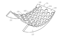
次に図20と図21は、排出用プレート73の変形例を示し、この排出用プレート73は、粉砕物が通過する多数の孔部155を有する円弧状平板体の本体部156と、粉砕室に円弧方向に沿って設けられたプレート嵌合溝66に嵌合するガイド部157とを備える。   Next, FIG. 20 and FIG. 21 show a modified example of the discharge plate 73. The discharge plate 73 has an arc-shaped flat plate body 156 having a large number of holes 155 through which the pulverized material passes, and a pulverization chamber. And a guide portion 157 fitted in a plate fitting groove 66 provided along the arc direction.

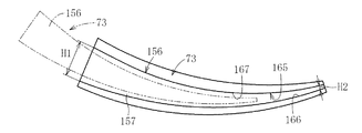
この排出用プレート73は、図20と図21に示すように、粉砕物が通過する多数の孔部155を有する円弧状平板体の本体部156と、粉砕室26の内側面に円弧方向に沿って設けられた一対の嵌合溝165(図22参照)に嵌合するガイド部157とを備える。このガイド部157を円弧状平板体の本体部156の側縁から垂下されるとともに円弧方向に沿ってその高さ寸法が変化するテーパ状とされている。すなわち、ガイド部157は、ケーシング本体31の開口部(側方開口部)40側の高さをH1とし、ケーシング本体31の内部側の高さをH2とした場合に、H1>H2となっている。   As shown in FIGS. 20 and 21, the discharge plate 73 has an arcuate plate body 156 having a large number of holes 155 through which the pulverized material passes, and an inner surface of the pulverization chamber 26 along the arc direction. And a guide portion 157 that fits into a pair of fitting grooves 165 (see FIG. 22). The guide portion 157 has a taper shape that hangs down from the side edge of the main body portion 156 of the arc-shaped flat plate and whose height dimension changes along the arc direction. That is, the guide portion 157 satisfies H1> H2 when the height on the opening (side opening) 40 side of the casing body 31 is H1 and the height on the inner side of the casing body 31 is H2. Yes.

また、プレート嵌合溝165は、図22に示すように、外径側受面部166と、内径側受面部167とを有し、外径側受面部166と内径側受面部167との間の間隔(嵌合溝の上下幅寸法)が円弧方向に沿って変化するテーパ状とされている。このため、ケーシング本体31の開口部(側方開口部)40を介して排出用プレート73は粉砕室26に出し入れ可能となっている。なお、排出用プレート73が粉砕室26に装着された状態(ガイド部157が嵌合溝165に嵌合した状態)では、本体部156は、ハンマー部材29の先端縁の円軌跡に沿った(対向)した曲率半径となる円弧形状となっている。   Further, as shown in FIG. 22, the plate fitting groove 165 has an outer diameter side receiving surface portion 166 and an inner diameter side receiving surface portion 167, and between the outer diameter side receiving surface portion 166 and the inner diameter side receiving surface portion 167. The interval (the vertical width dimension of the fitting groove) is a tapered shape that varies along the arc direction. For this reason, the discharge plate 73 can be taken into and out of the crushing chamber 26 through the opening (side opening) 40 of the casing body 31. In the state where the discharge plate 73 is mounted in the crushing chamber 26 (the guide portion 157 is fitted in the fitting groove 165), the main body portion 156 follows the circular locus of the tip edge of the hammer member 29 ( It has an arc shape with a radius of curvature facing each other.

前記排出用プレート73では、孔部155の孔径以下に粉砕された粉砕物のみを外部へ排出することができる。このため、被粉砕物を所望の大きさまで粉砕でき、粉砕機としての性能の向上を図ることができ、紙類、磁気テープ式記録媒体、光学式記録媒体、基板等の種々の情報媒体等を安定して粉砕できる。   In the discharging plate 73, only the pulverized material pulverized to the diameter of the hole 155 or less can be discharged to the outside. Therefore, the object to be crushed can be pulverized to a desired size, and the performance as a pulverizer can be improved. Various information media such as paper, magnetic tape recording media, optical recording media, and substrates can be used. Can be pulverized stably.

排出用プレート73を引き出す場合、高さ寸法大側を引き出せば、反引き出し側の高さ寸法が小さくなって、この高さ寸法小側が高さ寸法大側へ引き出されることになる。このため、図21の仮想線で示すように、嵌合溝165とガイド部157との間に順次隙間ができて、その引き出しの容易化を図ることができる。排出用プレート73及び粉砕室の清掃の容易化を図ることができる。   When pulling out the discharge plate 73, if the large height side is pulled out, the height dimension on the counter-drawing side becomes small, and the small height dimension side is pulled out to the large height side. For this reason, as shown by the phantom line in FIG. 21, a gap is sequentially formed between the fitting groove 165 and the guide portion 157, and the drawing can be facilitated. It is possible to facilitate the cleaning of the discharge plate 73 and the crushing chamber.

特に、蓋部材32を設けることによって、排出用プレート73の外部への引き出し作業、及び、外部からの排出用プレート73の挿入作業の容易化を図ることができ、作業性に優れた粉砕機となる。また、ガイド部157の高さ寸法は、蓋部材が装着される粉砕室の開口部側を高くすことによって、より一層排出用プレート73を出し入れ作用の容易化を図ることができる。   In particular, by providing the lid member 32, it is possible to facilitate the operation of pulling out the discharge plate 73 to the outside and the operation of inserting the discharge plate 73 from the outside, and a pulverizer excellent in workability. Become. In addition, the height of the guide portion 157 can be further facilitated by taking in and out the discharge plate 73 by increasing the opening side of the crushing chamber in which the lid member is mounted.

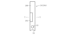
ところで、ハンマー部材29としては図22から図24に示すようなものであってもよい。この場合のハンマー部材(第2ハンマー部材)29bは、先端側に平板ハンマー部100を有し中央に粉砕刃101を有するものである。このハンマー部材29bにおいても、基端縁に回転軸45の外周面に嵌合する凹部50が形成されているとともに、この凹部50の近傍には、このハンマー部材29bの取り付け用の貫通孔53が設けられている。   Incidentally, the hammer member 29 may be as shown in FIGS. The hammer member (second hammer member) 29b in this case has a flat hammer portion 100 on the tip side and a crushing blade 101 in the center. Also in the hammer member 29b, a recess 50 that fits to the outer peripheral surface of the rotary shaft 45 is formed at the base edge, and a through-hole 53 for attaching the hammer member 29b is formed in the vicinity of the recess 50. Is provided.

このため、このハンマー部材29bにおいても、簡単にかつ短時間に回転軸45に取り付けることができ、回転軸45と一体に回転することができる。特に、このハンマー部材29を使用することによって、先端側の平板ハンマー部100にて被粉砕物を打撃できて破砕できる。また、粉砕室26の中央部においてハンマー部材29b等に絡まるテープ等を切断(せん断)することができる。   For this reason, this hammer member 29b can also be attached to the rotating shaft 45 easily and in a short time, and can rotate integrally with the rotating shaft 45. In particular, by using this hammer member 29, the object to be crushed can be hit and crushed by the flat plate hammer portion 100 on the front end side. Moreover, the tape etc. which are entangled with the hammer member 29b etc. in the center part of the crushing chamber 26 can be cut (sheared).

従って、この図22から図24に示すハンマー部材29bはカセットテープ類を粉砕するのに最適となる。なお、前記図6から図8に示すハンマー部材29aであっても、カセットテープ類の粉砕が可能であり、また、図22から図24に示すハンマー部材29bであっても、紙類の粉砕も可能である。   Therefore, the hammer member 29b shown in FIGS. 22 to 24 is optimal for crushing cassette tapes. 6 to 8, the cassette tapes can be crushed, and the hammer member 29b shown in FIGS. 22 to 24 can be crushed. Is possible.

各ハンマー部材29a,29bの取付け・取外しを簡単かつ短時間で行うことができるので、図22等に示すハンマー部材29bと、図6等に示すハンマー部材29aとを揃えておき、粉砕する被粉砕物に応じてハンマー部材29を交換するようにできる。   Since each hammer member 29a, 29b can be attached and detached easily and in a short time, the hammer member 29b shown in FIG. 22 and the like and the hammer member 29a shown in FIG. The hammer member 29 can be exchanged according to the object.

ハンマー部材29を複数種揃えることによって、被粉砕物の種類に応じてハンマー部材29を交換できる。このため、被粉砕物は粉砕するのに最適なハンマー部材29にて粉砕することができ、粉砕機としての粉砕精度が向上する。   By arranging a plurality of types of hammer members 29, the hammer members 29 can be exchanged according to the type of object to be crushed. Therefore, the object to be crushed can be crushed by the hammer member 29 that is optimal for pulverization, and the pulverization accuracy as a pulverizer is improved.

このように、前記粉砕機では、被粉砕物としては、基板(電子部品等が実装された基板)、カセットテープなどの磁気テープ式記録媒体、光学式記録媒体、紙等の種々のものが可能である。すなわち、この粉砕機では、硬いもの(例えば、基盤)から柔らかいもの(例えば、紙類)まで、一台で粉砕することができる。このため、従来では、投入する被粉砕物に材質、形状、大きさ、硬さ等によって、使用する粉砕機は選定されていたが、この粉砕機を用いれば、硬いものから柔らかいものまで幅の広い用途の粉砕を一台で可能となる。したがって、設備費用の低減を図ることができるとともに、ランニングコストも下がり、全体として処理費用も安くなって、個人情報の保護及びリサイクル性に優れる。   As described above, in the pulverizer, various objects such as a substrate (a substrate on which electronic parts are mounted), a magnetic tape recording medium such as a cassette tape, an optical recording medium, and paper can be used. It is. That is, with this pulverizer, it is possible to pulverize from a hard object (for example, a base) to a soft object (for example, paper) with a single machine. For this reason, conventionally, the pulverizer to be used has been selected depending on the material, shape, size, hardness, etc. of the material to be pulverized. A wide range of pulverization is possible with a single unit. Therefore, the facility cost can be reduced, the running cost is lowered, the processing cost is reduced as a whole, and the personal information is excellent in protection and recyclability.

以上、本発明の実施形態につき説明したが、本発明は前記実施形態に限定されることなく種々の変形が可能であって、例えば、前記実施形態では、自由状態で奥部蓋部材129が投入路120を塞いでない状態であるが、この自由状態で奥部蓋部材129が投入路構成体110の前壁113に当接して塞ぐ状態であってもよい。また、奥部蓋部材129を省略したものであってもよく、逆に、投入口蓋部材125と内部蓋部材128と奥部蓋部材129とに加えてさらに別の蓋部材を付設するものであってもよい。内部蓋部材128を奥部蓋部材129のように揺動板135等で構成しても、奥部蓋部材129を内部蓋部材128のように平板状の本体部と錘部とを備えたもので構成してもよい。投入口蓋部材125を閉状態とする弾性部材127としては、投入口蓋部材125を閉状態とする方向(図5(a)の矢印E方向)に弾性的を押圧できるものであれば、種々のバネ部材を使用することができる。投入口122の形状、大きさ等は、被粉砕物が投入できる範囲で種々変更できる。   As described above, the embodiment of the present invention has been described. However, the present invention is not limited to the above embodiment, and various modifications are possible. For example, in the above embodiment, the back cover member 129 is inserted in a free state. Although the road 120 is not blocked, the back cover member 129 may be in contact with the front wall 113 of the charging path structure 110 and closed in this free state. Further, the rear cover member 129 may be omitted, and conversely, in addition to the insertion port cover member 125, the inner cover member 128, and the rear cover member 129, another cover member is additionally provided. May be. Even if the inner lid member 128 is constituted by the swing plate 135 or the like like the inner lid member 129, the inner lid member 129 is provided with a flat plate-like main body portion and a weight portion like the inner lid member 128. You may comprise. As the elastic member 127 for closing the charging port lid member 125, various springs can be used as long as they can elastically press in the direction for closing the charging port lid member 125 (the direction of arrow E in FIG. 5A). A member can be used. The shape, size, and the like of the charging port 122 can be variously changed as long as the material to be crushed can be charged.

ハンマー部材集合体の数、および各ハンマー部材集合体のハンマー部材29の数の増減は任意である。一枚のプレート64、65に配置される固定刃47の数の増減も任意である。さらに、プレート嵌合溝66に嵌合されるプレート65の数やプレート65の周方向長さも任意に設定できる。   Increasing or decreasing the number of hammer member assemblies and the number of hammer members 29 in each hammer member assembly are arbitrary. Increasing or decreasing the number of fixed blades 47 arranged on one plate 64, 65 is also arbitrary. Furthermore, the number of plates 65 fitted in the plate fitting grooves 66 and the circumferential length of the plates 65 can be arbitrarily set.

固定刃47を固定するプレート65にも排出孔を設け、この排出孔から製品室(粉砕物収納室)に粉砕物を排出するようにしてもよい。また、この場合の排出孔や排出用プレートの排出孔74としては、円形孔にかぎらず、楕円孔、三角形孔、および矩形孔等の形状のものを採用でき、さらには、スリット孔等であってもよい。   A discharge hole may also be provided in the plate 65 for fixing the fixed blade 47, and the pulverized material may be discharged from the discharge hole into the product chamber (crushed material storage chamber). In this case, the discharge holes and the discharge holes 74 of the discharge plate are not limited to circular holes, but may be elliptical holes, triangular holes, rectangular holes, or the like, and may be slit holes or the like. May be.

前記実施形態では、蓋部材32に粉砕補助用凸部95を配置していたが、この粉砕補助用凸部95を省略しても、この粉砕補助用凸部95に代えて固定刃47を配置するようにしてもよい。   In the embodiment, the crushing assisting convex portion 95 is disposed on the lid member 32. However, even if the crushing assisting convex portion 95 is omitted, the fixed blade 47 is disposed in place of the crushing assisting convex portion 95. You may make it do.

さらに、ハンマー部材29の回転数としても、被粉砕物の種類等に応じて変更でき、この際、粉砕初期と粉砕終期とで回転数を変化させてもよい。この場合、粉砕初期においては低速とし、その後、次第に高速化したり、粉砕初期において低速で所定時間運転し、その後中速に切り替えて、この中速を所定時間運転し、次に高速に切り替えて、この高速を所定時間運転したりすることができる。   Further, the rotational speed of the hammer member 29 can be changed according to the type of the object to be crushed, and at this time, the rotational speed may be changed between the initial stage of pulverization and the final stage of pulverization. In this case, at the initial stage of pulverization, the speed is gradually increased, and then the speed is gradually increased, or at the initial stage of pulverization, the engine is operated at a low speed for a predetermined time. This high speed can be operated for a predetermined time.

排出プレート73の孔部155の形状、大きさ、数等は、粉砕物収納部へ排出する粉砕物に粒径等に応じて種々変更でき、また、孔部155としては、同一形状及び同一大きさとすることなく、異なる形状や異なる大きさのものがあってもよい。ガイド部157の高さ寸法の変位量も、排出プレート73の出し入れ性を考慮して種々変更できる。   The shape, size, number, and the like of the holes 155 of the discharge plate 73 can be variously changed depending on the particle size, etc., to the pulverized material discharged to the pulverized material storage unit, and the hole 155 has the same shape and the same size. Without limitation, there may be different shapes and sizes. The amount of displacement of the height of the guide portion 157 can be variously changed in consideration of the insertion / removal properties of the discharge plate 73.

図17と図18等にて示され固定刃は剛性が大であるので、案内路20に設け、この案内路20に投入される被粉砕物をこの固定刃150にて粉砕するようにしてもよい。また、各部位に配置される固定刃150の数や配置ピッチとしては、ハンマー部材の回転を損なわない範囲で種々変更することができる。   Since the fixed blade shown in FIGS. 17 and 18 has high rigidity, the fixed blade 150 may be used to grind the material to be crushed to be provided in the guide path 20 and put into the guide path 20. Good. Further, the number and arrangement pitch of the fixed blades 150 arranged in each part can be variously changed within a range not impairing the rotation of the hammer member.

本発明の実施形態を示す粉砕機の投入路を示す側面図である。It is a side view which shows the charging channel of the grinder which shows embodiment of this invention. 前記粉砕機の粉砕機本体の側面図である。It is a side view of the grinder main body of the said grinder. 前記粉砕機の粉砕機本体の蓋部材を外した状態の側面図である。It is a side view of the state which removed the lid member of the crusher main part of the crusher. 前記粉砕機の簡略正面図である。It is a simplified front view of the pulverizer. 粉砕機の投入路を示し、(a)は投入口蓋部材閉状態の簡略図であり、(b)は投入口蓋部材開状態の簡略図であり、(c)は内部蓋部材開状態の簡略図である。The charging path of a crusher is shown, (a) is a simplified view of the closing state of the charging port lid member, (b) is a simplified view of the opening state of the charging port lid member, and (c) is a simplified view of the open state of the internal lid member. It is. ハンマー部材の正面図である。It is a front view of a hammer member. ハンマー部材の側面図である。It is a side view of a hammer member. 図6のX−X線断面図である。It is the XX sectional view taken on the line of FIG. 切断刃と保持用プレートとを示す平面図である。It is a top view which shows a cutting blade and a holding plate. 切断刃を保持している保持用プレートの断面図である。It is sectional drawing of the plate for holding holding the cutting blade. ガイド体と保持用プレートとを示す平面図である。It is a top view which shows a guide body and a plate for holding. ガイド体を保持している保持用プレートの断面図である。It is sectional drawing of the plate for holding holding the guide body. 排出用プレートの平面図である。It is a top view of the plate for discharge. 排出用プレートの断面図である。It is sectional drawing of the plate for discharge | emission. 要部簡略図である。FIG. 案内路側の固定刃の変形例を示す平面図である。It is a top view which shows the modification of the fixed blade by the side of a guide path. 固定刃の変形例の正面図である。It is a front view of the modification of a fixed blade. 固定刃の変形例の側面図である。It is a side view of the modification of a fixed blade. ケーシング上壁側の固定刃の変形例を示す平面図である。It is a top view which shows the modification of the fixed blade of a casing upper wall side. 排出用プレートの変形例を示す斜視図である。It is a perspective view which shows the modification of the plate for discharge | emission. 前記図20の排出用プレートの簡略正面図である。FIG. 21 is a simplified front view of the discharging plate of FIG. 20. 粉砕室の簡略断面図である。It is a simplified sectional view of a crushing chamber. 他のハンマー部材の正面図である。It is a front view of another hammer member. 他のハンマー部材の側面図である。It is a side view of another hammer member. 図22のY−Y線断面図である。It is the YY sectional view taken on the line of FIG. 従来の粉砕機の断面図である。It is sectional drawing of the conventional grinder.

符号の説明Explanation of symbols

23 下部排出口
26 粉砕室
27 粉砕手段
29 ハンマー部材
45 回転軸
66 プレート嵌合溝
73 排出用プレート
98 邪魔板
120 投入路
122 投入口
125 投入口蓋部材
127 弾性部材
128 内部蓋部材
129 奥部蓋部材
130 本体板
131 錘部
135 揺動板
156 本体部
157 ガイド部
158 側壁
23 Lower discharge port 26 Crushing chamber 27 Crushing means 29 Hammer member 45 Rotating shaft 66 Plate fitting groove 73 Discharge plate 98 Baffle plate 120 Input path 122 Input port 125 Input port cover member 127 Elastic member 128 Internal cover member 129 Back cover member 130 Main body plate 131 Weight portion 135 Oscillating plate 156 Main body portion 157 Guide portion 158 Side wall

Claims (5)

被粉砕物を粉砕する粉砕手段が収容される粉砕室と、この粉砕室に被粉砕物を投入する投入路とを備えた粉砕機において、
前記投入路の投入口を塞ぐ投入口蓋部材と、投入路内部に設けられる内部蓋部材とを備え、前記投入口蓋部材は自由状態で弾性部材の弾性力にて投入口閉状態を維持し、弾性部材の弾性力に抗した内方への押圧により投入口開状態となるとともに、前記内部蓋部材は自由状態でその自重により投入路内部を塞ぎ、投入口開状態で投入路に入った被粉砕物による押圧で開状態となることを特徴とする粉砕機。
In a pulverizer equipped with a pulverization chamber in which a pulverization means for pulverizing the material to be crushed and an input path for introducing the material to be pulverized into the pulverization chamber,
A charging port cover member that closes the charging port of the charging channel; and an internal lid member that is provided inside the charging channel. The charging port lid member is in a free state and maintains the closing port closed by the elastic force of the elastic member. The inlet is opened by pressing inward against the elastic force of the member, and the inner lid member closes the inside of the inlet by its own weight in a free state, and enters the inlet in the inlet open state. A crusher characterized by being opened by pressing with an object.
前記投入路の前記内部蓋部材よりも粉砕室側に、粉砕室からの粉砕物の投入路への戻りを規制し、被粉砕物による押圧で粉砕室内への被粉砕物の投入を許容する奥部蓋部材を設けたことを特徴とする請求項1に記載の粉砕機。   The inside of the charging path is closer to the pulverization chamber than the inner lid member, and the return of the pulverized material from the pulverization chamber to the charging path is restricted, and the crushed material is allowed to be input into the pulverization chamber by pressing with the pulverized material The crusher according to claim 1, wherein a capping member is provided. 内部蓋部材は、その上端縁部が前記投入路内で枢結されて投入路閉状態と投入路開状態との変位が可能な平板状の本体板と、この本体板を投入路閉状態とする錘部とを備えたことを特徴とする請求項1又は請求項2に記載の粉砕機。   The inner lid member has a plate-like main body plate whose upper edge is pivoted in the input path so as to be displaceable between the input path closed state and the input path open state, and the main body plate is in the input path closed state. The pulverizer according to claim 1, further comprising a weight portion that performs the above operation. 奥部蓋部材は、上端縁部が前記投入路内で枢結された揺動板にて構成したことを特徴とする請求項1〜請求項3のいずれか1項に記載の粉砕機。   The crusher according to any one of claims 1 to 3, wherein the back cover member is configured by a swing plate whose upper edge is pivotally connected in the charging path. 投入路の粉砕室側に、粉砕室にて粉砕されてなる粉砕物の投入路への飛散を防止する撓性の邪魔板を配置したことを特徴とする請求項1〜請求項4にいずれか1項に記載の粉砕機。   The flexible baffle plate for preventing scattering of the pulverized material pulverized in the crushing chamber to the input path is disposed on the side of the input path in the crushing chamber. The crusher according to item 1.
JP2008073672A 2008-03-21 2008-03-21 Crusher Active JP5225719B2 (en)

Priority Applications (1)

Application Number Priority Date Filing Date Title
JP2008073672A JP5225719B2 (en) 2008-03-21 2008-03-21 Crusher

Applications Claiming Priority (1)

Application Number Priority Date Filing Date Title
JP2008073672A JP5225719B2 (en) 2008-03-21 2008-03-21 Crusher

Publications (2)

Publication Number Publication Date
JP2009226294A JP2009226294A (en) 2009-10-08
JP5225719B2 true JP5225719B2 (en) 2013-07-03

Family

ID=41242355

Family Applications (1)

Application Number Title Priority Date Filing Date
JP2008073672A Active JP5225719B2 (en) 2008-03-21 2008-03-21 Crusher

Country Status (1)

Country Link
JP (1) JP5225719B2 (en)

Families Citing this family (4)

* Cited by examiner, † Cited by third party
Publication number Priority date Publication date Assignee Title
EP3222355B1 (en) 2016-03-24 2018-10-24 Metso Minerals, Inc. Compact noise encapsulation for mobile processing devices
CN107442220A (en) * 2017-09-26 2017-12-08 江苏天琦生物科技有限公司 A kind of Chinese medicine crushing apparatus
CN107899731A (en) * 2017-12-04 2018-04-13 信宜市正茂农业科技发展有限公司 A kind of pulverizer
CN112742528A (en) * 2020-12-21 2021-05-04 郑叶芳 Raw materials grinder suitable for rubber product processing

Family Cites Families (7)

* Cited by examiner, † Cited by third party
Publication number Priority date Publication date Assignee Title
JPS534534Y2 (en) * 1972-08-08 1978-02-04
JPS5189384U (en) * 1975-01-14 1976-07-16
JPS6026818Y2 (en) * 1980-06-10 1985-08-13 株式会社 スタ−精機 Damper device in crusher
JPH0478942U (en) * 1990-11-16 1992-07-09
JPH0753708Y2 (en) * 1991-11-22 1995-12-13 株式会社ミチクラ Rotary impact crusher
JP2007196125A (en) * 2006-01-26 2007-08-09 Matsushita Electric Ind Co Ltd Hopper for crusher, and crusher
JP4412558B2 (en) * 2006-07-25 2010-02-10 晃立工業株式会社 Crusher

Also Published As

Publication number Publication date
JP2009226294A (en) 2009-10-08

Similar Documents

Publication Publication Date Title
JP4412558B2 (en) Crusher
JP5225719B2 (en) Crusher
US7677483B2 (en) Substrate destruction apparatus with shared rotating shaft
JP5225718B2 (en) Crusher
JP4514234B2 (en) Crusher
US7513448B2 (en) Paper and optical disk shredder
JP2010125419A (en) Crusher
CN217856561U (en) Automatic paper feeding shredder with paper cleaning structure
JP2006263655A (en) Crushing apparatus
JP2005066459A (en) Pulverizer
JP2008168196A (en) Waste tire cutting device
KR102529943B1 (en) Paper ahredder with remove device
JP2015136651A (en) Shredder
KR101567533B1 (en) Shredder for memory disk
JP2005305319A (en) Shredder
CN213254879U (en) Automatic paper shredder
KR20080089102A (en) Paper shredder installed cleaning fuction
JP2007007621A (en) Cover unit for charge opening of shredder
KR200440010Y1 (en) A crusher's feeder
KR200411210Y1 (en) Paper shredder attached seperated mater type cd scratcher
KR200384232Y1 (en) Paper shredder for chip decentralization device
JP2007307510A (en) Shredder
JP3139959U (en) Shredder slot mechanism and shredder having the same
JPH053227Y2 (en)
JP2005200125A (en) Rotary valve

Legal Events

Date Code Title Description
A621 Written request for application examination

Free format text: JAPANESE INTERMEDIATE CODE: A621

Effective date: 20110309

A977 Report on retrieval

Free format text: JAPANESE INTERMEDIATE CODE: A971007

Effective date: 20121220

TRDD Decision of grant or rejection written
A01 Written decision to grant a patent or to grant a registration (utility model)

Free format text: JAPANESE INTERMEDIATE CODE: A01

Effective date: 20130227

A61 First payment of annual fees (during grant procedure)

Free format text: JAPANESE INTERMEDIATE CODE: A61

Effective date: 20130313

R150 Certificate of patent or registration of utility model

Ref document number: 5225719

Country of ref document: JP

Free format text: JAPANESE INTERMEDIATE CODE: R150

Free format text: JAPANESE INTERMEDIATE CODE: R150

FPAY Renewal fee payment (event date is renewal date of database)

Free format text: PAYMENT UNTIL: 20160322

Year of fee payment: 3

R250 Receipt of annual fees

Free format text: JAPANESE INTERMEDIATE CODE: R250

R250 Receipt of annual fees

Free format text: JAPANESE INTERMEDIATE CODE: R250

R250 Receipt of annual fees

Free format text: JAPANESE INTERMEDIATE CODE: R250

R250 Receipt of annual fees

Free format text: JAPANESE INTERMEDIATE CODE: R250

R250 Receipt of annual fees

Free format text: JAPANESE INTERMEDIATE CODE: R250

R250 Receipt of annual fees

Free format text: JAPANESE INTERMEDIATE CODE: R250

R250 Receipt of annual fees

Free format text: JAPANESE INTERMEDIATE CODE: R250

R250 Receipt of annual fees

Free format text: JAPANESE INTERMEDIATE CODE: R250

R250 Receipt of annual fees

Free format text: JAPANESE INTERMEDIATE CODE: R250