JP5225291B2 - Connection box for photovoltaic modules - Google Patents
Connection box for photovoltaic modules Download PDFInfo
- Publication number
- JP5225291B2 JP5225291B2 JP2009548615A JP2009548615A JP5225291B2 JP 5225291 B2 JP5225291 B2 JP 5225291B2 JP 2009548615 A JP2009548615 A JP 2009548615A JP 2009548615 A JP2009548615 A JP 2009548615A JP 5225291 B2 JP5225291 B2 JP 5225291B2
- Authority
- JP
- Japan
- Prior art keywords
- clamp
- junction box
- housing
- insulating housing
- photovoltaic module
- Prior art date
- Legal status (The legal status is an assumption and is not a legal conclusion. Google has not performed a legal analysis and makes no representation as to the accuracy of the status listed.)
- Expired - Fee Related
Links
- 239000004020 conductor Substances 0.000 claims description 76
- 230000008878 coupling Effects 0.000 claims description 56
- 238000010168 coupling process Methods 0.000 claims description 56
- 238000005859 coupling reaction Methods 0.000 claims description 56
- 238000010248 power generation Methods 0.000 claims description 36
- 238000003780 insertion Methods 0.000 claims description 22
- 230000037431 insertion Effects 0.000 claims description 22
- 239000003292 glue Substances 0.000 claims description 8
- 238000000034 method Methods 0.000 claims description 7
- 238000003825 pressing Methods 0.000 claims description 4
- 230000004044 response Effects 0.000 claims description 4
- 230000007246 mechanism Effects 0.000 claims description 2
- 230000008569 process Effects 0.000 claims description 2
- 210000001331 nose Anatomy 0.000 description 8
- 238000004519 manufacturing process Methods 0.000 description 7
- 239000002184 metal Substances 0.000 description 7
- 229910052751 metal Inorganic materials 0.000 description 7
- 229920003023 plastic Polymers 0.000 description 6
- 239000000853 adhesive Substances 0.000 description 4
- 230000001070 adhesive effect Effects 0.000 description 4
- 238000005452 bending Methods 0.000 description 3
- RYGMFSIKBFXOCR-UHFFFAOYSA-N Copper Chemical compound [Cu] RYGMFSIKBFXOCR-UHFFFAOYSA-N 0.000 description 2
- 230000008901 benefit Effects 0.000 description 2
- 150000001875 compounds Chemical class 0.000 description 2
- 229910052802 copper Inorganic materials 0.000 description 2
- 239000010949 copper Substances 0.000 description 2
- 239000011521 glass Substances 0.000 description 2
- 239000011796 hollow space material Substances 0.000 description 2
- 238000009434 installation Methods 0.000 description 2
- 229910000679 solder Inorganic materials 0.000 description 2
- 229910000831 Steel Inorganic materials 0.000 description 1
- 230000003213 activating effect Effects 0.000 description 1
- 230000004888 barrier function Effects 0.000 description 1
- 230000008859 change Effects 0.000 description 1
- 230000002860 competitive effect Effects 0.000 description 1
- 230000001419 dependent effect Effects 0.000 description 1
- 238000011161 development Methods 0.000 description 1
- 230000018109 developmental process Effects 0.000 description 1
- 230000000694 effects Effects 0.000 description 1
- 230000005611 electricity Effects 0.000 description 1
- 238000005516 engineering process Methods 0.000 description 1
- -1 for example Chemical class 0.000 description 1
- 239000002803 fossil fuel Substances 0.000 description 1
- 238000001746 injection moulding Methods 0.000 description 1
- 230000003993 interaction Effects 0.000 description 1
- 230000005923 long-lasting effect Effects 0.000 description 1
- 239000000463 material Substances 0.000 description 1
- 229920000728 polyester Polymers 0.000 description 1
- 229920002620 polyvinyl fluoride Polymers 0.000 description 1
- 238000004080 punching Methods 0.000 description 1
- 230000000630 rising effect Effects 0.000 description 1
- 239000004065 semiconductor Substances 0.000 description 1
- 239000010959 steel Substances 0.000 description 1
- 239000010409 thin film Substances 0.000 description 1
Images


Classifications
-
- H—ELECTRICITY
- H01—ELECTRIC ELEMENTS
- H01R—ELECTRICALLY-CONDUCTIVE CONNECTIONS; STRUCTURAL ASSOCIATIONS OF A PLURALITY OF MUTUALLY-INSULATED ELECTRICAL CONNECTING ELEMENTS; COUPLING DEVICES; CURRENT COLLECTORS
- H01R4/00—Electrically-conductive connections between two or more conductive members in direct contact, i.e. touching one another; Means for effecting or maintaining such contact; Electrically-conductive connections having two or more spaced connecting locations for conductors and using contact members penetrating insulation
- H01R4/28—Clamped connections, spring connections
- H01R4/48—Clamped connections, spring connections utilising a spring, clip, or other resilient member
- H01R4/489—Clamped connections, spring connections utilising a spring, clip, or other resilient member spring force increased by screw, cam, wedge, or other fastening means
-
- H—ELECTRICITY
- H01—ELECTRIC ELEMENTS
- H01L—SEMICONDUCTOR DEVICES NOT COVERED BY CLASS H10
- H01L31/00—Semiconductor devices sensitive to infrared radiation, light, electromagnetic radiation of shorter wavelength or corpuscular radiation and specially adapted either for the conversion of the energy of such radiation into electrical energy or for the control of electrical energy by such radiation; Processes or apparatus specially adapted for the manufacture or treatment thereof or of parts thereof; Details thereof
- H01L31/02—Details
- H01L31/02002—Arrangements for conducting electric current to or from the device in operations
- H01L31/02005—Arrangements for conducting electric current to or from the device in operations for device characterised by at least one potential jump barrier or surface barrier
- H01L31/02008—Arrangements for conducting electric current to or from the device in operations for device characterised by at least one potential jump barrier or surface barrier for solar cells or solar cell modules
- H01L31/02013—Arrangements for conducting electric current to or from the device in operations for device characterised by at least one potential jump barrier or surface barrier for solar cells or solar cell modules comprising output lead wires elements
-
- H—ELECTRICITY
- H01—ELECTRIC ELEMENTS
- H01R—ELECTRICALLY-CONDUCTIVE CONNECTIONS; STRUCTURAL ASSOCIATIONS OF A PLURALITY OF MUTUALLY-INSULATED ELECTRICAL CONNECTING ELEMENTS; COUPLING DEVICES; CURRENT COLLECTORS
- H01R12/00—Structural associations of a plurality of mutually-insulated electrical connecting elements, specially adapted for printed circuits, e.g. printed circuit boards [PCB], flat or ribbon cables, or like generally planar structures, e.g. terminal strips, terminal blocks; Coupling devices specially adapted for printed circuits, flat or ribbon cables, or like generally planar structures; Terminals specially adapted for contact with, or insertion into, printed circuits, flat or ribbon cables, or like generally planar structures
- H01R12/50—Fixed connections
- H01R12/59—Fixed connections for flexible printed circuits, flat or ribbon cables or like structures
- H01R12/592—Fixed connections for flexible printed circuits, flat or ribbon cables or like structures connections to contact elements
-
- H—ELECTRICITY
- H01—ELECTRIC ELEMENTS
- H01R—ELECTRICALLY-CONDUCTIVE CONNECTIONS; STRUCTURAL ASSOCIATIONS OF A PLURALITY OF MUTUALLY-INSULATED ELECTRICAL CONNECTING ELEMENTS; COUPLING DEVICES; CURRENT COLLECTORS
- H01R9/00—Structural associations of a plurality of mutually-insulated electrical connecting elements, e.g. terminal strips or terminal blocks; Terminals or binding posts mounted upon a base or in a case; Bases therefor
- H01R9/22—Bases, e.g. strip, block, panel
- H01R9/24—Terminal blocks
- H01R9/2416—Means for guiding or retaining wires or cables connected to terminal blocks
-
- H—ELECTRICITY
- H02—GENERATION; CONVERSION OR DISTRIBUTION OF ELECTRIC POWER
- H02S—GENERATION OF ELECTRIC POWER BY CONVERSION OF INFRARED RADIATION, VISIBLE LIGHT OR ULTRAVIOLET LIGHT, e.g. USING PHOTOVOLTAIC [PV] MODULES
- H02S40/00—Components or accessories in combination with PV modules, not provided for in groups H02S10/00 - H02S30/00
- H02S40/30—Electrical components
- H02S40/34—Electrical components comprising specially adapted electrical connection means to be structurally associated with the PV module, e.g. junction boxes
-
- Y—GENERAL TAGGING OF NEW TECHNOLOGICAL DEVELOPMENTS; GENERAL TAGGING OF CROSS-SECTIONAL TECHNOLOGIES SPANNING OVER SEVERAL SECTIONS OF THE IPC; TECHNICAL SUBJECTS COVERED BY FORMER USPC CROSS-REFERENCE ART COLLECTIONS [XRACs] AND DIGESTS
- Y02—TECHNOLOGIES OR APPLICATIONS FOR MITIGATION OR ADAPTATION AGAINST CLIMATE CHANGE
- Y02E—REDUCTION OF GREENHOUSE GAS [GHG] EMISSIONS, RELATED TO ENERGY GENERATION, TRANSMISSION OR DISTRIBUTION
- Y02E10/00—Energy generation through renewable energy sources
- Y02E10/50—Photovoltaic [PV] energy
Landscapes
- Engineering & Computer Science (AREA)
- Electromagnetism (AREA)
- Sustainable Development (AREA)
- Sustainable Energy (AREA)
- Physics & Mathematics (AREA)
- Condensed Matter Physics & Semiconductors (AREA)
- Life Sciences & Earth Sciences (AREA)
- General Physics & Mathematics (AREA)
- Computer Hardware Design (AREA)
- Microelectronics & Electronic Packaging (AREA)
- Power Engineering (AREA)
- Photovoltaic Devices (AREA)
- Connection Or Junction Boxes (AREA)
- Non-Portable Lighting Devices Or Systems Thereof (AREA)
Description
本発明は、太陽光発電モジュールの表面から突出する可撓性の平坦導体帯を有する太陽光発電モジュールのための接続箱と、接続箱を太陽光モジュールに接続する方法とに関する。 The present invention relates to a junction box for a photovoltaic module having a flexible flat conductor band protruding from the surface of the photovoltaic module and a method for connecting the junction box to the photovoltaic module.
過去数年間にわたって、太陽光発電モジュールの生産は、文字通り、ブームになっていて、とりわけ、それは環境にやさしいエネルギー生産の要求の高まりに起因する。太陽光発電モジュールで、直接、太陽光を電流に変換することにより、完全に排出物質が無く、人間および環境にとってリスクが無いと、ほぼ言える。例えば、最近では、新しい建物の屋根には完全に太陽光発電モジュールがかぶせられ、“太陽光発電プラント”さえも建造されている。太陽光発電の技術的な進歩により、太陽光発電モジュールは中央ヨーロッパおよび北アメリカなど好ましくない緯度においてさえますます効率的になっており、とりわけこれらの地域において大きな需要が存在する。化石燃料または原子力エネルギーとしての他のエネルギー媒体でのエネルギー生産上のコストが上昇していることはいうまでもなく、一方においてさらなる技術的な発展に起因した太陽光モジュールの効率の継続的な進歩により、太陽光発電はますます競争的になっている。 Over the past few years, the production of photovoltaic modules has literally been booming, above all due to the increasing demand for environmentally friendly energy production. By directly converting sunlight into electric current with a solar power generation module, it can be almost said that there is no emission material and there is no risk to humans and the environment. For example, recently, the roof of a new building is completely covered with a photovoltaic module, and even a “solar power plant” has been built. Due to the technological advancement of photovoltaics, photovoltaic modules are becoming increasingly efficient even at unfavorable latitudes such as Central Europe and North America, and there is a great demand, especially in these regions. Needless to say, the cost of energy production in fossil fuels or other energy media as nuclear energy is rising, while on the other hand the continued advancement of the efficiency of solar modules due to further technological developments As a result, solar power generation is becoming increasingly competitive.
明らかに、他のエネルギー媒体との経済的競争において、太陽光モジュールの成功は、太陽光モジュールの生産および取付けコスト次第である。 Clearly, in economic competition with other energy media, the success of solar modules depends on the production and installation costs of the solar modules.
代表的に、太陽光モジュールは、半導体技術を基礎とする複数の太陽電池セルからなっていて、これらのセルが相互に接合されて、大規模な太陽電池パネルになる。代表的な太陽光モジュールは、太陽に面する側にガラス板を有し、背面に透明なプラスチック層を有していて、この層の中に太陽電池セルが埋設されている。代表的に、太陽光モジュールの背面は、例えば、ポリ弗化ビニルおよびポリエステルなどの耐候性プラスチック化合物の薄膜で被覆される。モノ型またはポリ型の結晶性の太陽電池セルは、小さな半田線によって互いに電気的に相互に接続されている。代表的に、太陽光発電モジュールは、さらに金属輪郭フレームに取り付けられ、該化合物を固定して剛性を高めている。従って、太陽光発電モジュールは、基本的に、厚いガラス板と同様な、二次元の存在である。 Typically, a solar module is composed of a plurality of solar cells based on semiconductor technology, and these cells are joined together to form a large-scale solar cell panel. A typical solar module has a glass plate on the side facing the sun and a transparent plastic layer on the back side, and solar cells are embedded in this layer. Typically, the back surface of the solar module is coated with a thin film of weathering plastic compound such as, for example, polyvinyl fluoride and polyester. Mono-type or poly-type crystalline solar cells are electrically connected to each other by small solder wires. Typically, the photovoltaic module is further attached to a metal contour frame, and the compound is fixed to increase the rigidity. Therefore, the photovoltaic power generation module is basically a two-dimensional existence similar to a thick glass plate.
代表的に、太陽光モジュールは、太陽から外れた側に、薄い平坦導体帯を有している。多くの場合、これらの帯は銅から作られており、太陽光発電モジュールの背面側から垂直に突出している。これらの平坦導体帯は極めて繊細であり、接続が困難である。加えて、太陽光発電モジュールが円板状の形状であるために、電気コネクタを固定するための機械的な挿入も困難である。従って、特殊な種類の電気コネクタが、そのような太陽光発電モジュールのために発達しており、この種類のものは結合箱または接続箱と称される。代表的に、接続箱は、太陽光発電モジュールの背面に接着され、太陽光発電モジュールにおける可撓性の平坦導体帯と接触するための電気結合装置を内部に有している。さらに、必要に応じて、接続箱は電気接続ケーブルを接続するための装置を有し、これが太陽光発電モジュールによって発生した電流を導くための接続箱によって、太陽光発電モジュールにおける可撓性の平坦導体帯と結合される。 Typically, a solar module has a thin flat conductor band on the side away from the sun. In many cases, these bands are made of copper and project vertically from the back side of the photovoltaic module. These flat conductor bands are extremely delicate and difficult to connect. In addition, since the photovoltaic power generation module has a disk shape, mechanical insertion for fixing the electrical connector is also difficult. Therefore, a special kind of electrical connector has been developed for such a photovoltaic module, this kind being called a coupling box or junction box. Typically, the junction box is bonded to the back surface of the photovoltaic module, and has an electrical coupling device for contacting the flexible flat conductor band in the photovoltaic module. In addition, if necessary, the junction box has a device for connecting electrical connection cables, which is a flexible flat in the photovoltaic module by means of a junction box for guiding the current generated by the photovoltaic module. Combined with the conductor band.
さらに、いくつかの太陽光発電モジュールは代表的に直列接続において動作し、いわゆるバイパスダイオードまたはフリーホイールダイオードは、それぞれのモジュールに逆並列で接続される。接続箱の内部では、フリーホイールダイオードが電気接続装置に接続されている。モジュールが日陰に入り、または欠陥のために電気を発生しないならば、モジュールは、直列接続における太陽光発電モジュールの出力を低下させ、または、バイパスダイオードが無ければ、損傷することさえある。これはバイパスダイオードによって回避される。電流がダイオードを通って流れ、持続するからである。 In addition, some photovoltaic modules typically operate in series connection, so-called bypass diodes or freewheeling diodes are connected in antiparallel to each module. Inside the junction box, a freewheeling diode is connected to the electrical connection device. If the module enters the shade or does not generate electricity due to a fault, the module can reduce the output of the photovoltaic module in series connection or even be damaged if there is no bypass diode. This is avoided by a bypass diode. This is because current flows through the diode and persists.
機械的な状態,特に太陽光発電モジュールの形態と可撓性の平坦導体帯の繊細さに起因して、明らかに、接続箱を構成する際に多数の困難が生じる。 Obviously, a number of difficulties arise in constructing the junction box due to the mechanical state, in particular the form of the photovoltaic module and the delicateness of the flexible flat conductor strip.
これまで、可撓性の平坦導体帯に装着される接続箱が知られている。その装着の際、可撓性の平坦導体帯は、手作業で曲げられて、接触クランプまたは半田付け接続によって、接続される。接続箱は、さらなる手順段階で、閉じられる。そのような接続配置または接続箱は、それぞれ、特許文献1および特許文献2に開示されている。そのような接続装置または接続箱を取り付けることは、それぞれ根気を要し、自動化された大量生産には適していないことが明らかである。
To date, connection boxes that are mounted on flexible flat conductor bands are known. During its mounting, the flexible flat conductor strip is bent manually and connected by contact clamps or solder connections. The junction box is closed in a further procedural step. Such connection arrangements or connection boxes are disclosed in
太陽光発電モジュールのための電気的な接続箱は特許文献3により知られるところであり、この箱はその下側に案内構造を有している。薄い導体帯はこの案内構造によって少ない遊びで横方向に案内され、クランプ装置の中に挿入するとき、導体帯が座屈または折り曲げられることを回避している。ここでは、導体帯を狭い案内構造にねじ入れなければならず、それにもかかわらず、クランプ構造の保持力は薄い導体帯をクランプ構造に挿入できるようにするため、比較的低く不利である。 An electrical connection box for a photovoltaic module is known from US Pat. No. 6,057,056, which has a guide structure on the underside. The thin conductor strip is guided laterally by this guide structure with little play, avoiding buckling or bending of the conductor strip when inserted into the clamping device. Here, the conductor band has to be screwed into a narrow guide structure, nevertheless, the holding force of the clamp structure is relatively low and disadvantageous in order to allow a thin conductor band to be inserted into the clamp structure.
これらすべてを見ると、太陽光発電モジュールの生産を革新するために、高い圧力によって、この観点を改良するための要望が存在している。 In view of all of these, there is a desire to improve this aspect with high pressure to innovate the production of photovoltaic modules.
従って、本発明の目的は、容易で、迅速で、効率的で、特に、自動的に、例えばロボットによって、太陽光発電モジュールに結合される太陽光発電モジュールのための接続箱を提供することである。 The object of the present invention is therefore to provide a junction box for a photovoltaic module which is easy, quick and efficient, in particular automatically, for example automatically coupled by means of a robot to the photovoltaic module. is there.
本発明のさらに別の目的は、高い接触信頼性と長寿命とを提供する、そのような接続箱を提供することである。 Yet another object of the present invention is to provide such a junction box that provides high contact reliability and long life.
本発明のさらに別の目的は、そのような接続箱であって、現在の技術水準における不都合を少なくとも軽減し、コスト効率的に、生産され、取り付けられるものを提供することである。 Yet another object of the present invention is to provide such a junction box that is produced and mounted cost-effectively, at least reducing the disadvantages of the current state of the art.
本発明の目的は、独立請求項に記載した内容によって解決される。有利な実施形態は、従属請求項の主題である。 The object of the present invention is solved by what is stated in the independent claims. Advantageous embodiments are the subject matter of the dependent claims.
本発明によれば、太陽光発電モジュールのための接続箱が提供され、太陽光発電モジュールの表面から突出した、一以上の可撓性の平坦導体帯と接触する。 In accordance with the present invention, a junction box for a photovoltaic module is provided that contacts one or more flexible flat conductor bands that protrude from the surface of the photovoltaic module.
接続箱は、太陽光発電モジュールに装着される絶縁ハウジングを備え、ハウジングの下側には挿入口を有している。“下側側面”という用語は、空間内における絶対的な向きの意味に理解されないことは明らかであるが、接続箱またはハウジングのそれぞれの側面は、下側と称され、取り付け状態における太陽光発電モジュールに対向する。すなわち、この側が、太陽光発電モジュールと係合する。 The junction box includes an insulating housing attached to the photovoltaic power generation module, and has an insertion port on the lower side of the housing. Obviously, the term “lower side” is not understood in the sense of absolute orientation in space, but each side of the junction box or housing is referred to as the lower side, which means Opposite the module. That is, this side engages with the photovoltaic power generation module.
ハウジングの下側には挿入口が設けられ、その中にはハウジングが挿入口にて平坦導体帯に装着されたとき、平坦導体帯は自動的に挿入される。特に、挿入口は平坦導体帯のサイズに比べて本質的に大きく形成されており、平坦導体帯がハウジングの中に真っ直ぐに自由に挿入され、ハウジングによって案内されることがない。これは、平坦導体帯がハウジングと係合しないという利点を有している。これにより、特に、挿入中に帯が折り曲げられて、繊細な平坦導体帯を損傷させる危険が回避される。 An insertion port is provided on the lower side of the housing, and when the housing is mounted on the flat conductor band at the insertion port, the flat conductor band is automatically inserted. In particular, the insertion slot is essentially larger than the size of the flat conductor band, and the flat conductor band is freely inserted straight into the housing and is not guided by the housing. This has the advantage that the flat conductor strip does not engage the housing. This avoids, in particular, the risk of the band being bent during insertion and damaging the delicate flat conductor band.
ハウジング内には、電気的な結合装置が配置され、これは可撓性の平坦導体帯と電気的に接触するための接触クランプを有している。ハウジングが太陽光発電モジュールに装着され、平坦導体帯を覆っている取付状態においては、接触クランプは開かれていて、開いた接触クランプの内側の自由領域中に、繊細な平坦導体帯が衝突せずに挿入されることを可能にしている。この領域では、接触クランプを閉じるとき、平坦導体帯は、受け取られ(把持され)および接触する。従って、接触クランプのこの領域は、キャッチ領域と称される。しかるに、接続箱は2つの異なる状態を有し、すなわち、接触クランプが開かれた取付状態と、接触クランプが閉じられて、平坦導体帯を保持し、これと電気的に接触する、接触状態とがある。 An electrical coupling device is disposed within the housing and has a contact clamp for making electrical contact with the flexible flat conductor strip. In the mounting state where the housing is mounted on the photovoltaic module and covers the flat conductor band, the contact clamp is open and the delicate flat conductor band collides with the free area inside the open contact clamp. Without being inserted. In this region, the flat conductor strip is received (gripped) and contacts when closing the contact clamp. This area of the contact clamp is therefore called the catch area. However, the junction box has two different states: a mounting state in which the contact clamp is opened, and a contact state in which the contact clamp is closed to hold the flat conductor strip and make electrical contact therewith. There is.
接触クランプを閉じるには、すなわち接続箱を取付状態から接触状態に変化させるには、接続箱を太陽光発電モジュールに装着して、可撓性の平坦導体帯をハウジングに挿入した後で、作動構造によって接触クランプを活動的に作動させる。接続箱の設計に応じて、作動は、単一の生産段階における取付工程中に直ちに実行され、または第2の段階における取付けの後に実行される。そのために、作動構造は、ハウジングの内側に作動ノーズを備え、これは、例えば、作動裂け目または作動ピンであって、力を適用して、接触クランプを開き、および接触クランプを閉じる。 To close the contact clamp, i.e. to change the junction box from the mounted state to the contact state, the junction box is mounted on the photovoltaic module and the flexible flat conductor strip is inserted into the housing and then activated. The structure activates the contact clamp actively. Depending on the junction box design, the actuation is performed immediately during the mounting process in a single production stage, or after the mounting in the second stage. To that end, the actuating structure comprises an actuating nose inside the housing, which is, for example, an actuating crevice or actuating pin that applies a force to open and close the contact clamp.
本発明においては、活動的に閉じる接触クランプによって、有利に、平坦導体帯を把持するクランプ力を選択可能であり、望むならば、高くできる。これは、接触の信頼性と耐久性とに対して、有利に影響する。 In the present invention, the actively closing contact clamp advantageously allows the clamping force to grip the flat conductor strip to be selected and increased if desired. This has an advantageous effect on the reliability and durability of the contact.
本発明の好ましい実施形態によれば、ハウジングは、少なくとも2部品から形成され、2つのハウジング部分は、例えば、互いに対して摺動可能であるように、互い対して可動になっている。取付状態においては、2つのハウジング部分のうち第1の部分は、さらに、2つのハウジング部分のうち第2の部分を、太陽光発電モジュールを向いている側に於いて、突き出している。従って、接続箱に装着したとき、最初に、2つのハウジング部分のうち第1の部分だけが太陽光発電モジュールと係合する。接続箱は、この第1のハウジング部分に取り付けられる。第2のハウジング部分を太陽光発電モジュールに向けて押すことで、互いに対する2つのハウジング部分の動きが、およびそれとともに結合装置に対する第2のハウジング部分の動きが、開始される。というのは、結合装置を有する第1のハウジング部分は、太陽光発電モジュールにそれ自体を支持し、第2のハウジング部分に固定された作動構造が、自動的に接触クランプを閉じるためである。従って、有利な点としては、外部からハウジングを係合することで、もっぱら接触クランプが閉じられて、手作業の介入はない。 According to a preferred embodiment of the invention, the housing is formed from at least two parts, the two housing parts being movable relative to each other, for example so that they can slide relative to each other. In the mounted state, the first part of the two housing parts further protrudes the second part of the two housing parts on the side facing the photovoltaic module. Therefore, when mounted on the junction box, only the first part of the two housing parts is initially engaged with the photovoltaic module. A junction box is attached to the first housing part. Pushing the second housing part towards the photovoltaic module initiates the movement of the two housing parts relative to each other and with it the movement of the second housing part relative to the coupling device. This is because the first housing part with the coupling device supports itself to the photovoltaic module and the actuating structure fixed to the second housing part automatically closes the contact clamp. Thus, the advantage is that by engaging the housing from the outside, the contact clamp is closed exclusively and there is no manual intervention.
この目的のために、2つのハウジング部分のうち、一方は複数の案内スリーブを有すると都合が良く、また、他方のハウジング部分は、それに対応する整列ピンを有し、これらが一緒になって、太陽光発電モジュールの表面に対して垂直な直動ガイドを形成している。取付状態においては、整列ピンは、特に好ましくは、案内スリーブに未だ完全に挿入されておらず、この位置で自己ロックまたは自己クランプで固定されていて、第2のハウジング部分が、例えば、取付ロボットによって取り外され、上から太陽光発電モジュールに装置されるとき、第1のハウジング部分は結合装置と共に落下することはない。接続箱を太陽光発電モジュールに装着したとき、摺動構造における自己ロックは、第1のハウジング部分に対して第2のハウジング部分の移動を喚起するために太陽光発電モジュールに向けて第2のハウジング部分に力を負荷することで克服され、第2のハウジング部分にて作動構造によって、接触クランプを閉じる。従って、接触クランプを閉じることは、接続箱を相対的な動きによって装着するとき、自動的に実行される。 For this purpose, one of the two housing parts advantageously has a plurality of guide sleeves, and the other housing part has a corresponding alignment pin, which together, A linear guide perpendicular to the surface of the photovoltaic module is formed. In the mounted state, the alignment pin is particularly preferably not yet fully inserted into the guide sleeve and is fixed in this position by self-locking or self-clamping, so that the second housing part is, for example, a mounting robot The first housing part does not fall with the coupling device when removed by and installed in the photovoltaic module from above. When the junction box is attached to the photovoltaic module, the self-locking in the sliding structure is second toward the photovoltaic module to urge movement of the second housing part relative to the first housing part. It is overcome by applying a force to the housing part and the contact clamp is closed by the actuating structure in the second housing part. Thus, closing the contact clamp is automatically performed when the junction box is mounted by relative movement.
これらの手段は、特に、容易で効率的な自動化された取付けを可能にするが、それは、主として、接続箱を太陽光発電モジュールに装着するとき、取付ロボットが接続箱を供給構造から取り上げて、太陽光発電モジュールに対して垂直に直動することだけが必要な場合に当てはまる。 These means in particular allow easy and efficient automated installation, mainly because when the connection box is mounted on the photovoltaic module, the mounting robot picks up the connection box from the supply structure, This is the case when it is only necessary to move directly perpendicular to the photovoltaic module.
従って、第1のハウジング部分は太陽光発電モジュールと係合するための底部要素として形成されるが、同時に、結合装置のための保持として働き、結合装置は、底部要素に固定して結合される。このために、底部要素は、ラッチ要素を提供し、例えば、これによって、結合装置は底部要素に係止される。第2のハウジング部分は、キャップ部分として形成される。2つのハウジング部分のうち少なくとも一方、つまり、好ましくはキャップ部分は、外周に側壁を有し、第1および第2のハウジング部分が一緒になって、例えば、下側および接続ケーブルを挿入するための側壁に設けられた所定の開口部を除き、ハウジングが接触状態において太陽光発電モジュールに固定されて結合されたとき、結合構造のための閉じられた少なくとも水しぶきに対して不浸透性の箱を形成する。好ましくは、キャップ部分は、山型帽子状に形成され、外周に唇部を有し、接触状態において、太陽光発電モジュールの表面に、キャップ部分を接着するためのグルー切欠部を備えている。接触状態においては、キャップ要素はいうまでもなく底部要素は、太陽光発電モジュールに対して面一に当接する。しかるに、底部要素は、必ずしも接続箱における底部全体をカバーする必要はない。底部要素の寸法は、太陽光発電モジュールに支持し、接続箱を固定するというその機能を満足すれば、むしろ充分である。望むならば、キャップ要素に加えて、底部要素は、太陽光発電モジュールに接着される。 Thus, the first housing part is formed as a bottom element for engaging the photovoltaic module, but at the same time serves as a holding for the coupling device, the coupling device being fixedly coupled to the bottom element . For this purpose, the bottom element provides a latch element, for example, whereby the coupling device is locked to the bottom element. The second housing part is formed as a cap part. At least one of the two housing parts, i.e. preferably the cap part, has a side wall on the outer periphery, the first and second housing parts together, e.g. for inserting the lower and connecting cables Except for certain openings provided in the side walls, when the housing is fixed and coupled to the photovoltaic module in contact, it forms a box that is impervious to closed at least splashes for the coupling structure To do. Preferably, the cap portion is formed in a mountain-shaped hat shape, has a lip portion on the outer periphery, and is provided with a glue notch portion for bonding the cap portion to the surface of the photovoltaic power generation module in a contact state. In the contact state, not only the cap element but also the bottom element abuts against the photovoltaic module. However, the bottom element does not necessarily have to cover the entire bottom of the junction box. The dimension of the bottom element is rather sufficient if it supports its function of supporting the photovoltaic module and fixing the junction box. If desired, in addition to the cap element, the bottom element is glued to the photovoltaic module.
好ましくは、接触クランプは、例えば、ばね金属でできているクランプばねでカウンタクランプ要素とを備えたばね力クランプとして形成され、ばね力クランプは接触状態において自発的に開き、作動構造によって適用される力によって閉じられる。このために、クランプばねを開いた状態で係止するラッチ機構を有し、例えばそれはラッチノーズの形態であって、取付状態において、接触クランプの保持フレームの箇所で突出部の背面に固定されることに打ち勝つかのように、禁止できる。これにより、接触クランプは、作動構造によってスナップ嵌合が開くのを克服して、活動的に閉じられるまで、作動しているとき、しっかりと開いて保持される。 Preferably, the contact clamp is formed as a spring force clamp with a counter clamp element, for example a clamp spring made of spring metal, the spring force clamp opening spontaneously in contact and the force applied by the actuating structure Closed by. For this purpose, it has a latch mechanism that locks the clamp spring in an open state, for example, it is in the form of a latch nose and is fixed to the back of the protrusion at the location of the holding frame of the contact clamp in the mounted state It can be banned as if to overcome. This keeps the contact clamp open and held securely when activated until it is actively closed, overcoming the snap fit opening by the actuation structure.
特に、好ましくは、接触クランプは、クランプばねおよび/またはカウンタクランプ要素と共に使用され、結合装置における保持フレームに回動可能に取り付けられる。接触クランプを作動させると、次に、少なくとも1つのクランプばねの回動、または接触クランプを閉じるためのカウンタクランプ要素の回動を生じさせ、従って、可撓性の平坦導体帯との電気的な接触が閉じられる。好ましくは、平坦導体帯は、太陽光発電モジュールの法線に対して角度をなすように(例えば、45゜または90゜)、接触する。従って、2つの接触要素(ばねクランプおよびカウンタクランプ要素)の間における接触クランプの接触力は、太陽光発電モジュールの表面に対して垂直なベクトル成分を有している。接触クランプの形態に応じて、高くて長持ちする接触の信頼性にもかかわらず、作動構造は、ここでは簡素化される。 In particular, the contact clamp is preferably used with a clamp spring and / or a counter clamp element and is pivotally attached to a holding frame in the coupling device. Activating the contact clamp then causes rotation of at least one clamp spring or counter-clamp element to close the contact clamp, and thus electrical contact with the flexible flat conductor strip. Contact is closed. Preferably, the flat conductor strips are in contact with each other at an angle (eg 45 ° or 90 °) to the normal of the photovoltaic module. Therefore, the contact force of the contact clamp between the two contact elements (spring clamp and counter clamp element) has a vector component perpendicular to the surface of the photovoltaic module. Depending on the form of the contact clamp, the operating structure is simplified here despite the high and long lasting contact reliability.
以下、2つの実施形態について詳細に説明する。すなわち、1つでは、可撓性の平坦導体帯は、接続箱が装着されたとき、開かれた接触クランプにおける開いたキャッチ領域の中に直接挿入される。別の実施形態では、可撓性の平坦導体帯は、接続箱が装着されるとき、最初に、ハウジングの開いた中間的領域の中に挿入され、接続箱は可撓性の平坦導体帯のための偏向構造を有し、この構造は、可撓性の平坦導体帯を、中間的領域から接触クランプのキャッチ領域の中に曲げこむ。2つ目に述べられる実施形態においては、偏向構造は、好ましくは、偏向アームを備え、このアームは、接続箱が太陽光発電モジュールに装着されたときに作動して、可撓性の平坦導体帯が曲げられた後にキャッチ領域に延在するように挿入口を通して挿入した後で、可撓性の平坦導体帯をハウジングの中の接触クランプに向けて曲げこみ、次に、接触クランプを閉じることで、把持および電気的に接触させる。 Hereinafter, two embodiments will be described in detail. That is, in one, the flexible flat conductor strip is inserted directly into the open catch area in the open contact clamp when the junction box is installed. In another embodiment, the flexible flat conductor strip is first inserted into the open intermediate region of the housing when the junction box is installed, and the junction box is formed of the flexible flat conductor strip. A deflection structure for bending a flexible flat conductor band from the intermediate region into the catch region of the contact clamp. In the second described embodiment, the deflecting structure preferably comprises a deflecting arm, which is actuated when the junction box is mounted on the photovoltaic module and is a flexible flat conductor. After insertion through the insertion slot so that it extends into the catch area after the band is bent, the flexible flat conductor band is bent towards the contact clamp in the housing and then the contact clamp is closed And hold and make electrical contact.
説明される両方の実施形態に共通することは、先に説明した現在の技術水準とは対照的に、接触クランプは、薄い平坦導体帯によって押し開かれることがなく、平坦導体帯は、最初には、実質的に抵抗を受けず、接続箱のハウジング内の開いた領域の中に、挿入口を通して全体的に挿入されることである。特に、挿入口は、平坦導体帯の横断面寸法に比べてかなり大きくなっている。有利には、繊細な平坦導体帯を損傷する危険は、これにより減少する。 Common to both described embodiments is that, in contrast to the current state of the art described above, the contact clamp is not pushed open by a thin flat conductor band, Is substantially free of resistance and is generally inserted through the insertion opening into an open area in the housing of the junction box. In particular, the insertion opening is considerably larger than the cross-sectional dimension of the flat conductor band. Advantageously, this reduces the risk of damaging delicate flat conductor bands.
以下、本発明について、実施形態と図面とに基づいて、より詳細に説明することとし、図面において、両方の実施形態にて同一または類似の要素には、同一の参照符号を付しており、2つの実施形態の特徴は、互いに組み合わせることができるものである。 Hereinafter, the present invention will be described in more detail based on embodiments and drawings. In the drawings, the same or similar elements in both embodiments are denoted by the same reference numerals, The features of the two embodiments can be combined with each other.
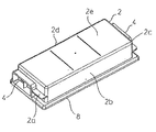
図1および図2を参照すると、接続箱は、プラスチックから作られたハウジングキャップ2を有している。ハウジングキャップ2は、4つの側壁2aから2dと、太陽光発電モジュールに対して平行に延在する閉じたキャップ板2eとから作られた、実質的に矩形のフレームによって形成されている。ハウジングキャップ2は、5つの側面で閉じられて、下向きに開いている。例えば、これは、プラスチックの射出成形から作られる。別々の折曲保護鳩目6(図3および図4参照)は、それぞれ、接続ケーブルのリードスルー4に挿入されている。
Referring to FIGS. 1 and 2, the junction box has a
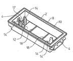
図2を参照すると、ハウジングキャップは下向きに開いていて、保持フレーム8は外向きに突出していて、このフレームは外周にグルー切欠部10を有し、ハウジングキャップ2は、山型帽子状の形状を有している。最終的には、接続箱は、グルー切欠部10に挿入された接着剤によって、太陽光発電モジュール上に永久的に接着される。ハウジングキャップの山型帽子状またはフライパン状の形状は、内側に中空空間12を形成し、その中に、図2には示していない結合装置が、取付状態において、実質的に防水されて配置される。
Referring to FIG. 2, the housing cap is opened downward, the holding
整列ピン14は、キャップ板2eの下側から、中空空間12に延在している。不図示の接続ケーブルのためのクランプバー17は、2つの整列ピン14の間において、接続ケーブルのリードスルー4の内側に提供されている。さらに、キャップ板2eの下側には、2つの作動構造18が設けられる。この実施形態においては、作動構造18は、その機能についてさらに詳しく説明するが、横方向に延在する作動バーとして形成され、ハウジングキャップ2と一体的に形成されている。
The
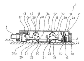
図3を参照すると、2つの同一である結合装置20が、接続箱1のハウジング3の中に配置され、このハウジングは、ハウジングキャップ2と底部要素50とから形成されている。2つの結合装置20は同一に形成されているので、2つの結合装置20のうち一方だけについて、以下に説明する。
Referring to FIG. 3, two
図3は、取付状態における接続箱を示しており、接触クランプ22は開いている。底部要素50には、結合装置20が取り付けられ、案内スリーブ15を有し、その中に整列ピン14が挿入される。整列ピン14は、関連する案内スリーブ15をクランプし、接続箱1が太陽光発電モジュール24に装着されたとき、底部要素50はハウジングキャップ2にてクランプされて保持され、ハウジング3はハウジングキャップ2にて把持され、自動的に装着され、底部要素50および結合装置20が落下することがない。一方、結合装置20でハウジングキャップ2と底部要素50との間の相対的な動きを可能とする力を加えることで、すなわち、最小力を越えるならば、整列ピン14と案内スリーブ15との間のクランプは打ち勝つかもしれない。この例においては、案内スリーブ15には、スロットが設けられ、整列ピン14でのクランプ共作用の克服を改善する。
FIG. 3 shows the junction box in the mounted state, with the
開いた取付状態においては、結合装置20は未だ完全にはハウジングキャップ2の中に挿入されておらず、底部要素50は、ハウジングキャップ2から若干(数ミリメートル)だけ下向きに突出し、すなわち、太陽光発電モジュールに対面する側に突出している。従って、取付状態においては、底部要素50の下側50aと、ハウジングキャップ2の保持フレーム8との間にはオフセットが存在し、接続箱1を装着したとき、最初に、底部要素50は太陽光発電モジュール24に係合し、図3に示したこの状態においては、保持フレーム8は、依然として、太陽光発電モジュール24における表面24aから離間している。
In the open mounting state, the
底部要素50は、その下側50aに、太陽光発電モジュール24と対面するように、比較的大きな口26を有している。取付状態においては、繊細な可撓性の平坦導体帯28、いわゆる“リボン”が、バリアフリーで抵抗無く、下から挿入され挿入口26を通って、ハウジング3および結合装置20の中に入る。平坦導体帯28を破損する危険は、これにより減少する。この状態において、接触クランプ22は、開いたキャッチ領域31を形成し、ここに、接続箱を装着したとき、平坦導体帯28が下から侵入する。好ましくは、接触クランプ22と平坦導体帯28との間には、未だ接触が存在せず、平坦導体帯の挿入および接触は、2つの連続した段階において行われる。
The
ここで、ハウジングキャップ2には、太陽光発電モジュール24に対して力が加えられ、しかるに接触クランプを閉じる一方、底部要素50はそれ自体を太陽光発電モジュール24にて支持する。ハウジングキャップ2と結合装置20を備えた底部要素50との間の直動的な相対運動によって、ハウジングキャップ2は、グルー切欠部10を備えた保持フレーム8が、太陽光発電モジュール24の表面24aに係合するまで、底部要素50と接触クランプ20とにかぶせられて摺動する効果を有し、底部要素50とハウジングキャップ2との下側は、太陽光発電モジュール24と面一に当接する。この状態は、図4に示される。
Here, a force is applied to the
図4を参照すると、ハウジングキャップ2は、グルー切欠部10の中にある接着剤によって、太陽光発電モジュールに接着される。しかし、底部要素50については、太陽光発電モジュール24に接着する必要がない。ハウジングキャップ2が、底部要素50および結合装置20に向けて相対的に運動する間、この例においては、作動構造18と作動バーが、クランプばね32と共に、さらに相互作用する。この作動のために、接触クランプ22は、クランプばね32を回動することで閉じられる。そのために、クランプばね32におけるクランプ部分34は、キャッチ領域31を通り抜け、平坦導体帯の上端部を把持し、クランプばね32のクランプ部分34と、カウンタクランプ要素36との間において、それと電気的にクランプ接触する。そうするとき、平坦導体帯28は屈曲されるが、というのは、この例においては、カウンタクランプ要素26は、太陽光発電モジュールの法線に対して、約45゜傾斜しているためである。
Referring to FIG. 4, the
クランプばね32は、作動部分38を有し、これは、屈曲した部分40と、実質的に直線状の部分42とに分割される。閉じるとき、作動要素18は、最初に、屈曲部分40に作用し(図3参照)、接続箱1の閉じた状態において、直線状部分42に対して締め付けられ、この状態を図4に示している。すなわち、閉じるとき、作動要素18は、クランプばね32の作動部分18を通り過ぎる。
さらに、結合装置20は、不図示の接続ケーブルのためのケーブル接続クランプ40を有している。
Furthermore, the
この例においては、ケーブル接続クランプ40にも、クランプばね48が設けられる。これに関して、ねじクランプなど、その他の接続変形例を使用できる。
In this example, the
ここに示した実施形態においては、接続箱1は、2つの同一に形成された結合装置20を備え、2つの平坦導体帯28に同時に接触する。しかし、本発明がそれに限定されないことは明らかであり、接続箱1は、1つだけのまたは2つを越える結合装置20を備えることができる。
In the embodiment shown here, the
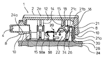
図5を参照すると、結合装置20は、底部要素50に取り付けられ、これは、この例においては、好ましくはプラスチックから作られた、絶縁キャリアとして形成されている。底部要素50の下側50aは、太陽光発電モジュール24に係合する主たる領域と、挿入口26とを形成している。結合装置20はさらに、実質的にU字形の金属製の保持フレームを、好ましくは銅から作られて有しており、これは、スナップ嵌合52によって、底部要素50に係止される。
Referring to FIG. 5, the
図5および図6は、接触クランプ22の閉じた接触状態を示しており、接触クランプ22は係止されている。このために、クランプばね32は、2つのラッチ軸を有し、これらは、金属製の保持フレーム51における対応するノーズ55の背面に係止される。クランプばね32は、この係止された状態においては、カウンタクランプ36に対して予張力を与えられている。これは、永久的なしっかりした電気接触を与える。平坦導体帯28は、図5および図6には示していない。
5 and 6 show the closed contact state of the
さらに、クランプばね32は、ベアリング軸56によって、スロット付きのベアリング開口部58に吊下される。従って、接続箱を生産するとき、クランプばね32は容易に挿入される。平坦ベアリング軸の位置に起因して、この位置は、取付状態および接触状態において、軸60に対して回動し、クランプばね32が固定される。クランプばね32は、鋼板から打ち抜いて形成され、実質的にU字形に屈曲している。
Further, the
金属製の保持フレーム51はさらに、バイパスダイオードのための絶縁結合要素を有し、この要素は、底部要素50にあるソケット62によって支持される。
The
クランプばね32の作動部分38における2つの部分40,42の形態に起因して、クランプばね32は、開いた取付状態において固定され、キャッチ領域31は取付状態において開いて保たれる。接続箱1を太陽光発電モジュールに装着することで、導電帯28は、太陽光発電モジュールから突出して、図1乃至図6に示した実施形態の場合には、下から直接、このキャッチ領域31に達する。
Due to the configuration of the two
ハウジングキャップ2と、結合装置20を備えた底部要素50との間の相互作用に起因して、作動要素18によって、クランプばね32は、開いた位置に強制的に残され、回動を生じる。
Due to the interaction between the
平坦導体帯28は、キャッチ領域31内にあって、クランプ部分34によって把持され、この例においては、45゜の角度の回動を維持することで、カウンタクランプ要素36に押し付けられる。回動の終了時には、クランプばねは、そのラッチノーズ54と共に、接触または運転状態において、金属製の保持フレーム51の中に係止する(図4)。クランプばね32の予張力に起因して、平坦導体帯28とカウンタクランプ要素36との間には、永久的で所定の押圧力が確立する。
The
再び図2を参照すると、この例においては、4つの整列ピン14が設けられ、ハウジングキャップ2における横方向に異なる位置にて、結合装置20を底部要素50に配置できるようになっている。
Referring again to FIG. 2, in this example, four
図7および図8は、本発明の第2の実施形態に従った接続箱1を示しており、ハウジングキャップ2は、むしろ正方形に形成されて、第1の実施形態(図1乃至図6)におけるように次々と並べる代わりに、2つの結合装置20を横並びに配置する。接触クランプ22および摺動構造14,15は、第1の実施形態と第2の実施形態とにおいて、ほとんど同一に形成されているので、繰り返しを避けることとして、第1の実施形態の説明を参照されたい。
FIGS. 7 and 8 show a
キャップ板2eの下側には、偏向アームを作動させるための横方向カムの形状である、第1の作動構造14を有している(図8には不図示。図9乃至図11を参照。)。さらに、接触クランプを作動させるための作動ピン18が、キャップ板2eから、ハウジングキャップ2の内部空間内に突出している。この実施形態においては、カム16と作動装置18とは、ハウジングキャップ2と一体的に形成されている。
Below the
図9乃至図11を参照すると、結合構造20は、接続箱1のハウジング3の中に配置されている。図12を参照すると、接続箱は、2つの同一である結合装置20を有し、以下、2つのうち一方だけを参照する。
9 to 11, the
図9は、平坦導体帯28にかぶせられた後の接続箱を示している。かぶせたとき、接続箱は、第1の状態、つまり取付状態にあり、偏向アーム21は第1の位置にある。取付状態は、好ましくは接続箱がもたらされる状態であり、挿入口26の上の中間的領域30は、空洞に保たれ、接触クランプ22は開いている。
FIG. 9 shows the junction box after being covered with the
接続箱1は、比較的大きい挿入口26を有し、太陽光発電モジュールに対面する側に設けられる。これは、いわゆる“リボン”である繊細な可撓性の平坦導体帯28が、取付状態において、バリアフリーで抵抗無く下から接続箱内に挿入されることを意味する。平坦導体帯28を破損する危険は、これにより減少する。この状態において、接続箱1は、接触クランプ22と偏向アーム21との間に、開いた中間的または挿入領域30を形成し、この領域には、接続箱を装着したとき、平坦導体帯28が、抵抗無く、下から入る。好ましくは、この状態においては、接触クランプ22または偏向アーム21と、平坦導体帯28との間に未だ接触は存在しない。
The
ここで、ハウジングキャップ2には、太陽光発電モジュール24に対して力が加えられ、平坦導体帯28を接触させ、結合装置20は、それ自体を太陽光発電モジュール24に支持する。結合構造20を備えた底部要素50に対するハウジングキャップ2の直接運動は、グルー切欠部10の中の接着剤(図示せず)を備えた保持フレーム8が、太陽光発電モジュール24の表面に係合するまで、ハウジングキャップ2が結合装置20にかぶせて摺動され、底部要素50の下側側面50aとハウジングキャップ2とが、太陽光発電モジュール24に面一に当接するようになっている。この閉じた接触状態は、最終的または運転状態を表し、図11に示されている。運転状態においては、ハウジング3は、グルー切欠部10の中にある接着剤によって、太陽光発電モジュール24に接着される。
Here, a force is applied to the
しかし、接続箱1が最終的状態に達する前に、接続箱は、図10に示した中間的状態を経由し、この状態においては、平坦導体帯28は既に曲げられ、接触クランプ22は依然として開いている。接続箱1を装着するとき、平坦導体帯は、従って、最初に、挿入領域30の中に挿入される。続いて、底部要素50の下側側面50aが太陽光発電モジュール24に係合した後で、平坦導体帯28は、曲げられて、偏向アーム21によって、接触クランプ22におけるキャッチ領域31の中に入る。さらに続いて、接触クランプ22は、第2の作動要素18によって、活動的に閉じられる。従って、接続箱1は、3つの事前に定義された状態を呈し、すなわち、偏向アーム21が第1の位置にあり、キャッチ領域は空洞で、接触クランプ22が開かれている、取付状態(図9)と、平坦導体帯28は、偏向アーム21によって依然として開いている接触クランプ22のキャッチ領域の中に、曲げられて入れられる中間的状態(図10)と、接触クランプ22が閉じられ、クランプ接触によって、平坦導体帯28との電気的接触を確立する、最終的または運転状態(図11)とである。この実施形態では、平坦導体帯28の接触は、太陽光発電モジュール24の表面に対して平行に実行される。
However, before the
ハウジングキャップ2と底部要素50と結合装置20との間の相対的な運動中に、第1の作動要素16、この例においては、作動カムは、従って、最初に、偏向アーム21と相互作用し、その後に、第2の作動要素18、この例においては、作動ピンはクランプばね32と相互作用する。この連続的な作動によって、偏向アーム21における屈曲部分21aは、最初に、カム16による作動に応答して、偏向される。その後に、接触クランプ22は、クランプばね22を回動することで閉じられる。この例においては、カム16は、ハウジングキャップ2の側壁のノーズとして形成され、ハウジングキャップ2と一体的になっている。その後に、クランプばね32におけるクランプ部分34は、接触クランプにおけるキャッチ領域31を通り過ぎ、クランプばね32のクランプ部分34とカウンタクランプ要素36との間に、平坦導体帯28の自由端をクランプして接触する。偏向アーム21におけるクランプ部分21aは、折曲ヒンジ21bによって、保持部分21cと一体的に結合される。保持部分21cは、底部要素50に取り付けられ、より正確には、底部要素と共に一体的に形成される。
During the relative movement between the
図12を参照すると、接続箱1は、この例においては、2つの結合装置20を備えている。結合装置は、頂部にて絶縁性の底部要素50に取り付けられる。図12は、開いた取付状態において、接触クランプ22を示している。クランプばね32は、2つのラッチノーズ54を有し、これらはそれぞれ、開いた取付状態においては、金属製の保持フレーム53における凹部53を克服してクランプする。
Referring to FIG. 12, the
次に、再び図9乃至図11を参照する。ハウジングキャップ2と、結合装置20が取り付けられたプラスチック製の底部要素50とが一緒に働くので、偏向アーム21の屈曲部分21aと、クランプばね21とは、作動要素16および18によって回動する。回動動作の終了時には、クランプばねは、接触状態(図11)においては、保持フレーム51のノーズ55の背部で、ラッチノーズ54に係止される。クランプばね32の予張力のために、平坦導体帯28と、導電カウンタクランプ要素36との間には、永久的で所定の押圧力が確立される。
Next, referring to FIGS. 9 to 11 again. Since the
当業者には明らかなように、上述した実施形態は例示として理解されるべきであり、本発明は、それらに限定されないが、本発明の範囲から逸脱せずに、様々な方法で変形できる。特に、接続箱は、1つの箱内に、一以上の接触クランプを有し、一以上の平坦導体帯と接触できる。さらに、明らかに、特徴は、個々に、本発明の本質的部分を形成し、たとえ、それらが他の特徴と一緒に一般的に説明されていたとしても、それらが説明、図面、または別な具合に開示されているか否かにかかわりない。 As will be apparent to those skilled in the art, the above-described embodiments are to be understood as illustrative and the present invention is not limited thereto but can be modified in various ways without departing from the scope of the invention. In particular, the junction box has one or more contact clamps in one box and can contact one or more flat conductor bands. Further, obviously, the features individually form an essential part of the invention, even if they are generally described together with other features, they may be described, illustrated, or otherwise described. It doesn't matter whether it is disclosed or not.
Claims (13)
作動構造(18)を有し、前記太陽光発電モジュール(24)に装着される絶縁ハウジング(3)であって、その絶縁ハウジング(3)は前記太陽光発電モジュール(24)に面する側(50a)に挿入口(26)が配置され、前記作動構造(18)は前記絶縁ハウジング(3)の内側に配置される前記絶縁ハウジング(3)と、
前記絶縁ハウジング(3)が前記太陽光発電モジュール(24)に装着された際において前記絶縁ハウジング(3)内に配置される結合装置(20)であって、クランプばね(32)とカウンタクランプ要素(36)とを有する接触クランプ(22)を有する前記結合装置(20)と,
偏向アーム(21)を備え、
前記絶縁ハウジング(3)が前記太陽光発電モジュール(24)に装着される前記接続箱(1)の装着状態では、前記クランプばね(32)と前記カウンタクランプ要素(36)とは、前記クランプばね(32)と前記カウンタクランプ要素(36)との間に空間を維持するように配置されていて、前記少なくとも1つの可撓性の平坦導体(28)は前記挿入口(26)から前記絶縁ハウジング(3)内に導入され、
そしてさらに、前記絶縁ハウジング(3)の前記太陽光発電モジュール(24)への装着が進んだ装着の中間状態では、前記絶縁ハウジング(3)が前記太陽光発電モジュール(24)に装着される動きに応じて前記偏向アーム(21)で前記少なくとも1つの可撓性の平坦導体(28)を前記空間内に折り込み、
前記絶縁ハウジング(3)が前記太陽光発電モジュール(24)に完全に装着された前記接続箱(1)の取付状態では、前記絶縁ハウジング(3)の前記作動構造(18)が前記クランプばね(32)に押圧力を与えて前記クランプばね(32)は前記接触クランプ(22)の前記空間を閉じて前記空間内の前記少なくとも1つの可撓性の平坦導体(28)を前記カウンタクランプ要素(36)上に押し付けて、前記接触クランプ(22)と前記少なくとも1つの可撓性の平坦導体(28)とを電気的に接続することを特徴とする接続箱。 A junction box (1) for the photovoltaic module (24) having at least one flexible flat conductor (28) protruding from the surface of the photovoltaic module, the junction box comprising:
An insulating housing (3) having an operating structure (18) and attached to the photovoltaic module (24), the insulating housing (3) facing the photovoltaic module (24) ( 50a) is provided with an insertion port (26), and the operating structure (18) is disposed inside the insulating housing (3), the insulating housing (3);
A coupling device (20) disposed in the insulating housing (3) when the insulating housing (3) is mounted on the photovoltaic power generation module (24), comprising a clamp spring (32) and a counter clamp element Said coupling device (20) having a contact clamp (22) having (36);
A deflection arm (21),
In the mounted state of the connection box (1) in which the insulating housing (3) is mounted on the photovoltaic power generation module (24), the clamp spring (32) and the counter clamp element (36) are the clamp spring. (32) and the counter clamp element (36) are arranged to maintain a space, the at least one flexible flat conductor (28) from the insertion opening (26) to the insulating housing. Introduced in (3),
Further, in the intermediate state of the mounting in which the mounting of the insulating housing (3) to the solar power generation module (24) is advanced, the movement of mounting the insulating housing (3) to the solar power generation module (24). In response, the deflection arm (21) folds the at least one flexible flat conductor (28) into the space,
In the attached state of the junction box (1) in which the insulating housing (3) is completely attached to the photovoltaic power generation module (24), the operating structure (18) of the insulating housing (3) is the clamp spring ( 32), the clamp spring (32) closes the space of the contact clamp (22) and pushes the at least one flexible flat conductor (28) in the space to the counter clamp element ( 36) A junction box that presses onto and electrically connects the contact clamp (22) and the at least one flexible flat conductor (28) .
前記絶縁ハウジング(3)は、互いに可動な少なくとも2つの部材(2,50)から形成され、
前記可動な少なくとも2つのハウジング部分(2,50)は、該太陽光発電モジュール(24)の表面(24a)に対して横方向に、互いに対して摺動可能であって、
前記作動構造(18)が前記クランプばね(32)を押圧する動作は、前記可動な少なくとも2つのハウジング部分(2,50)のお互いに対しての移動に応答して生じることを特徴とする接続箱。 The junction box according to claim 1,
The insulating housing (3) is formed of at least two members (2, 50) movable relative to each other,
The movable at least two housing parts (2, 50) are slidable relative to each other in a direction transverse to the surface (24a) of the photovoltaic module (24);
Connection wherein the actuating structure (18) presses the clamp spring (32) occurs in response to movement of the movable at least two housing parts (2, 50) relative to each other. box.
前記絶縁ハウジング(3)は、摺動構造(14,15)を有し、
前記摺動構造(14,15)は案内スリーブに案内された複数の整列ピンを有し、前記整列ピンは前記可動な少なくとも2つのハウジング部分(2,50)に設けられていることを特徴とする接続箱。 The junction box according to claim 2,
The insulating housing (3) has a sliding structure (14, 15);
The sliding structure (14, 15) has a plurality of alignment pins guided by a guide sleeve, the alignment pins being provided on the movable at least two housing parts (2, 50). Connection box to do.
前記摺動構造(14,15)は、取付状態において自己ロック式であり、前記可動な少なくとも2つのハウジング部分のうちの第1のハウジング部分(50)は、前記可動な少なくとも2つのハウジング部分のうちの第2のハウジング部分(2)だけを把持して取り扱う際に、落下しないように配置されていることを特徴とする接続箱。 The junction box according to claim 2 or 3,
The sliding structure (14, 15) is self-locking in the mounted state, and a first housing part (50) of the movable at least two housing parts is of the at least two movable housing parts. A junction box which is arranged so as not to drop when only the second housing part (2) is gripped and handled.
前記可動な少なくとも2つのハウジング部分のうちの第1のハウジング部分(50)は、装着状態において、前記太陽光発電モジュール(24)を向いた側において、前記可動な少なくとも2つのハウジング部分のうちの第2のハウジング部分(2)を突き出し、該接続箱(1)が前記太陽光発電モジュール(24)上に載置された際に、まず前記第1のハウジング部分(50)のみが前記太陽光発電モジュール(24)と係合し、しかるに前記第1のハウジング部分(50)に対する該第2のハウジング部分(2)の移動は、前記作動構造(18)により前記接触クランプ(22)を閉じるために、前記太陽光発電モジュール(24)の方向に向かって該第2のハウジング部分(2)に力を付与することにより引き起こされることを特徴とする接続箱。 The junction box according to claim 4,
The first housing part (50) of the at least two movable housing parts is mounted on the side facing the photovoltaic module (24) in the mounted state, of the at least two movable housing parts. When the second housing part (2) is protruded and the junction box (1) is placed on the photovoltaic power generation module (24), only the first housing part (50) is the sunlight. The movement of the second housing part (2) relative to the first housing part (50) is engaged with the power generation module (24), so that the actuating structure (18) closes the contact clamp (22). Further, it is caused by applying a force to the second housing part (2) in the direction of the photovoltaic module (24). That junction box.
前記第1のハウジング部分(50)は、前記太陽光発電モジュール(24)に係合するための底部要素として形成され、該第2のハウジング部分(2)はキャップ部分として形成され、前記可動な少なくとも2つのハウジング部分のうち少なくとも一方は、外周に側壁(2aからd)を有し、前記第1のハウジング部分(50)および前記第2のハウジング部分(2)は共に、事前に形成された開口部を除いて閉じられて、前記絶縁ハウジング(3)が接触状態において太陽光発電モジュール(24)としっかり結合されたとき、少なくとも水しぶきに対して不浸透性の箱を結合構造(1)が備えることを特徴とする接続箱。 The junction box according to claim 4 or 5,
The first housing part (50) is formed as a bottom element for engaging with the photovoltaic module (24), the second housing part (2) is formed as a cap part and is movable. At least one of the at least two housing parts has side walls (2a to d) on the outer periphery, both the first housing part (50) and the second housing part (2) being pre-formed When the insulating housing (3) is closed with the exception of the opening and is firmly connected with the photovoltaic module (24) in contact, the combined structure (1) forms a box that is impervious to at least splashing. A junction box characterized by comprising.
前記キャップ部分は外周に唇部(8)を有し、前記キャップ部分(2)を太陽光発電モジュール(24)の表面(24a)に接着するためのグルー切欠部を備えていることを特徴とする接続箱。 The junction box according to claim 6,
The cap portion has a lip portion (8) on the outer periphery, and has a glue notch portion for bonding the cap portion (2) to the surface (24a) of the photovoltaic power generation module (24). Connection box to do.
前記接触クランプ(22)において、前記クランプばね(32)と前記カウンタクランプ要素(36)とは、前記クランプばね(32)への前記絶縁ハウジング(3)の前記作動構造(18)の押圧力に抗するようなばね力を形成し、前記クランプばね(32)と前記カウンタクランプ要素(36)との間における前記空間の維持はそのばね力によって生じることを特徴とする接続箱。 A junction box according to any one of claims 1 to 7,
In the contact clamp (22) , the clamp spring (32) and the counter clamp element (36) are subjected to a pressing force of the operating structure (18) of the insulating housing (3) on the clamp spring (32). A junction box, wherein a spring force is formed to resist, and the space between the clamp spring (32) and the counter clamp element (36) is maintained by the spring force.
前記接触クランプ(22)はラッチ機構(54,55)を有し、これにより接触ばね(32)は接触状態に係止されることを特徴とする記載の接続箱。 A junction box according to any one of claims 1 to 8,
The junction box according to claim 1, wherein the contact clamp (22) has a latch mechanism (54, 55), whereby the contact spring (32) is locked in a contact state.
前記絶縁ハウジング(3)が前記太陽光発電モジュール(24)に装着される際には、前記少なくとも1つの可撓性の平坦導体帯(28)は、ほぼ無抵抗で前記挿入口(26)から挿通可能であることを特徴とする接続箱。 The junction box according to any one of claims 1 to 9,
When the insulating housing (3) is attached to the photovoltaic power generation module (24), the at least one flexible flat conductor strip (28) is substantially non-resisting from the insertion opening (26). A junction box that can be inserted.
その太陽光発電モジュールの表面(24a)から突出する少なくとも1つの可撓性の平坦導体帯(28)と、
請求項1から10のいずれか一項に記載の少なくとも1つの接続箱(1)とを備えることを特徴とする太陽光発電モジュール。 It is a photovoltaic power generation module, and the photovoltaic power generation module is
At least one flexible flat conductor strip (28) protruding from the surface (24a) of the photovoltaic module;
A photovoltaic module comprising at least one junction box (1) according to any one of claims 1 to 10 .
太陽光発電モジュール(24)の表面(24a)から、前記少なくとも1つの可撓性の平坦導体帯(28)を突出する前記太陽光発電モジュール(24)を準備する工程と、
作動構造(18)を有し、前記太陽光発電モジュール(24)に装着される絶縁ハウジング(3)であって、その絶縁ハウジング(3)は前記ハウジングの側(50a)に挿入口(26)が配置され、前記作動構造(18)は前記絶縁ハウジング(3)の内側に配置される前記絶縁ハウジング(3)と、
前記絶縁ハウジング(3)が前記太陽光発電モジュール(24)に装着された際において前記絶縁ハウジング(3)内に配置される結合装置(20)であって、クランプばね(32)とカウンタクランプ要素(36)とを有する接触クランプ(22)を有する前記結合装置(20)と、
偏向アーム(21)とを備える工程と、
前記絶縁ハウジング(3)が前記太陽光発電モジュール(24)に装着される前に、前記クランプばね(32)と前記カウンタクランプ要素(36)とは、前記クランプばね(32)と前記カウンタクランプ要素(36)との間に空間を維持するように配置して、前記絶縁ハウジング(3)が前記太陽光発電モジュール(24)に装着されるにしたがって、前記少なくとも1つの可撓性の平坦導体(28)は前記挿入口(26)から前記絶縁ハウジング(3)内を導入する工程と、
その後、前記絶縁ハウジング(3)が前記太陽光発電モジュール(24)に装着される動きに応じて前記偏向アーム(21)で前記少なくとも1つの可撓性の平坦導体(28)を前記空間内に折り込む工程と、
さらに前記絶縁ハウジング(3)の前記太陽光発電モジュール(24)への装着が進むにしたがって、前記絶縁ハウジング(3)の前記作動構造(18)が前記クランプばね(32)に押圧力を与えて前記クランプばね(32)は前記接触クランプ(22)の前記空間を閉じて前記空間内の前記少なくとも1つの可撓性の平坦導体(28)を前記カウンタクランプ要素(36)上に押し付けて、前記接触クランプ(22)と前記少なくとも1つの可撓性の平坦導体(28)とを電気的に接続する工程とを具備する方法。 Method for coupling a junction box (1) for the photovoltaic module (24) having at least one flexible flat conductor (28) protruding from the surface of the photovoltaic module to the photovoltaic module (24) And the method is
Preparing the photovoltaic module (24) projecting the at least one flexible flat conductor strip (28) from the surface (24a) of the photovoltaic module (24);
An insulating housing (3) having an operating structure (18) and attached to the solar power generation module (24), the insulating housing (3) being an insertion port (26) on the side (50a) of the housing Wherein the actuating structure (18) is disposed inside the insulating housing (3), and the insulating housing (3) ,
A coupling device (20) disposed in the insulating housing (3) when the insulating housing (3) is mounted on the photovoltaic power generation module (24), comprising a clamp spring (32) and a counter clamp element Said coupling device (20) having a contact clamp (22) having (36) ;
Comprising a deflection arm (21);
Before the insulating housing (3) is attached to the photovoltaic module (24), the clamp spring (32) and the counter clamp element (36) are the clamp spring (32) and the counter clamp element. (36) so as to maintain a space between the at least one flexible flat conductor (as the insulating housing (3) is mounted on the photovoltaic module (24)). 28) introducing the inside of the insulating housing (3) from the insertion port (26);
Thereafter, the at least one flexible flat conductor (28) is moved into the space by the deflection arm (21) in accordance with the movement of the insulating housing (3) attached to the photovoltaic module (24). Folding process,
Further , as the mounting of the insulating housing (3) to the photovoltaic power generation module (24) proceeds, the operating structure (18) of the insulating housing (3) applies a pressing force to the clamp spring (32). The clamp spring (32) closes the space of the contact clamp (22) and presses the at least one flexible flat conductor (28) in the space onto the counter clamp element (36), Electrically connecting the contact clamp (22) and the at least one flexible flat conductor (28) .
前記絶縁ハウジング(3)は、底部要素(50)とキャップ部分(2)とから形成された、少なくとも2部品からなり、前記結合装置(20)は、前記底部要素(50)に取り付けられると共に、前記底部要素(50)と一緒に、前記キャップ部分(2)に対して摺動可能であり、前記摺動装置(14,15)は、別々の自己ロック式であり、前記底部要素(50)と前記結合装置(20)とは、前記接続箱(1)を太陽光発電モジュール(24)に装着されたとき、キャップ部分(2)から落下することがなく、前記底部要素(50)は前記キャップ部分(2)から下向きに突出し、前記太陽光発電モジュール(24)に装着されたとき、最初に、前記底部要素(50)だけが、太陽光発電モジュールの表面(24a)に係合し、
前記太陽光発電モジュール(24)に向けて前記キャップ部分(2)から力が加えられ、前記キャップ部分(2)は前記太陽光発電モジュール(24)と係合するまで、前記キャップ部分(2)は、前記底部要素(50)と前記結合装置(20)とに対してシフトして、前記キャップ部分(2)と前記底部要素(50)との相対的な動きに応答して、前記接触クランプ(22)は前記空間を自動的に閉じることを特徴とする方法。 The method of claim 12, comprising:
The insulating housing (3) consists of at least two parts formed from a bottom element (50) and a cap part (2), the coupling device (20) being attached to the bottom element (50), Along with the bottom element (50) is slidable with respect to the cap part (2), the sliding device (14, 15) being a separate self-locking and the bottom element (50) And the coupling device (20) means that when the junction box (1) is attached to the photovoltaic power generation module (24), it does not fall from the cap part (2), and the bottom element (50) When projecting downward from the cap part (2) and being mounted on the photovoltaic module (24), only the bottom element (50) initially engages the surface (24a) of the photovoltaic module,
A force is applied from the cap portion (2) toward the photovoltaic module (24) until the cap portion (2) engages the photovoltaic module (24). Are shifted with respect to the bottom element (50) and the coupling device (20) and in response to the relative movement of the cap part (2) and the bottom element (50), the contact clamp (22) The method is characterized in that the space is automatically closed.
Applications Claiming Priority (9)
| Application Number | Priority Date | Filing Date | Title |
|---|---|---|---|
| DE200710006433 DE102007006433A1 (en) | 2007-02-05 | 2007-02-05 | Connection box for electrically connecting solar module, has clamp spring passing from one position into another position during attachment of housing upper part on housing lower part, so that connection line is automatically contactable |
| DE102007006433.2 | 2007-02-05 | ||
| DE102007037130A DE102007037130B3 (en) | 2007-08-07 | 2007-08-07 | Junction box and connecting box for use in connecting device for photovoltaic solar module, comprises flexible flat conductor strip that protrude from surface of solar module, where junction device has electric contact clip |
| DE102007037130.8 | 2007-08-07 | ||
| DE102007042457.5 | 2007-09-07 | ||
| DE200710042457 DE102007042457A1 (en) | 2007-09-07 | 2007-09-07 | Valve actuator for a fully variable valve train |
| DE102007051134A DE102007051134B4 (en) | 2007-09-07 | 2007-10-24 | Connection and connection box for a solar module |
| DE102007051134.7 | 2007-10-24 | ||
| PCT/EP2008/000859 WO2008095670A1 (en) | 2007-02-05 | 2008-02-04 | Junction box and connecting box for a solar module |
Related Child Applications (1)
| Application Number | Title | Priority Date | Filing Date |
|---|---|---|---|
| JP2013000069A Division JP5550748B2 (en) | 2007-02-05 | 2013-01-04 | Connection box for photovoltaic modules |
Publications (3)
| Publication Number | Publication Date |
|---|---|
| JP2010518564A JP2010518564A (en) | 2010-05-27 |
| JP2010518564A5 JP2010518564A5 (en) | 2010-07-08 |
| JP5225291B2 true JP5225291B2 (en) | 2013-07-03 |
Family
ID=41170026
Family Applications (2)
| Application Number | Title | Priority Date | Filing Date |
|---|---|---|---|
| JP2009548615A Expired - Fee Related JP5225291B2 (en) | 2007-02-05 | 2008-02-04 | Connection box for photovoltaic modules |
| JP2013000069A Expired - Fee Related JP5550748B2 (en) | 2007-02-05 | 2013-01-04 | Connection box for photovoltaic modules |
Family Applications After (1)
| Application Number | Title | Priority Date | Filing Date |
|---|---|---|---|
| JP2013000069A Expired - Fee Related JP5550748B2 (en) | 2007-02-05 | 2013-01-04 | Connection box for photovoltaic modules |
Country Status (3)
| Country | Link |
|---|---|
| US (1) | US8033859B2 (en) |
| JP (2) | JP5225291B2 (en) |
| CN (1) | CN101606294B (en) |
Cited By (1)
| Publication number | Priority date | Publication date | Assignee | Title |
|---|---|---|---|---|
| JP2016213020A (en) * | 2015-05-01 | 2016-12-15 | Smk株式会社 | Connector for cable connection |
Families Citing this family (25)
| Publication number | Priority date | Publication date | Assignee | Title |
|---|---|---|---|---|
| DE102008062034B4 (en) * | 2008-12-12 | 2010-08-12 | Tyco Electronics Amp Gmbh | Connecting device for connection to a solar module and solar module with such a connection device |
| ES2376517T3 (en) * | 2009-07-03 | 2012-03-14 | Tyco Elektronics Amp Gmbh | PUMP BOX FOR CONNECTING A SOLAR CELL, ELECTRICAL DIODE, GUIDE ELEMENT AND FIXING MEANS. |
| JP5063657B2 (en) * | 2009-10-07 | 2012-10-31 | 日本航空電子工業株式会社 | Contact and connection device having the same |
| US8187016B2 (en) * | 2010-03-05 | 2012-05-29 | Xunlight Corporation | Terminal assembly including a junction box for a photovoltaic module and method of forming |
| US20110240088A1 (en) * | 2010-03-31 | 2011-10-06 | Ats Automation Tooling Systems Inc. | One-piece junction box |
| DE102010029714A1 (en) * | 2010-04-08 | 2011-10-13 | Tyco Electronics Amp Gmbh | Electrical spring clamp, punched grid, busbar and electrical connection device |
| CN201754409U (en) * | 2010-06-30 | 2011-03-02 | 比亚迪股份有限公司 | Solar battery terminal box |
| WO2012083049A1 (en) * | 2010-12-17 | 2012-06-21 | First Solar, Inc | Electrical connection system |
| EP2546932A3 (en) * | 2011-07-15 | 2015-06-24 | Hosiden Corporation | Terminal box and terminal box fixing arrangement |
| CN102956731A (en) * | 2011-08-23 | 2013-03-06 | 杜邦太阳能有限公司 | Solar junction box |
| US20130048334A1 (en) * | 2011-08-29 | 2013-02-28 | Tyco Electronics Corporation | Junction box |
| JP5729648B2 (en) * | 2011-10-13 | 2015-06-03 | ホシデン株式会社 | Terminal box for solar cell module |
| ITAV20120004A1 (en) * | 2012-11-23 | 2014-05-24 | Sunnytech Srl | JUNCTION BOX OF MODULES OR PHOTOVOLTAIC PANELS WITH SURFACE MOUNTING (SURFACE MOUNT TECHNOLOGY, SMT) WATERPROOF IP68, COOLED FOR NATURAL CONVENTION, SELF-CENTERING WITH AUTOMATIC COLLECTION AND POSITIONING SYSTEMS (PICK & PLACE) |
| US9660406B2 (en) * | 2013-08-30 | 2017-05-23 | The Patent Store Llc | Push-in wire connector with collar |
| US10402922B2 (en) * | 2014-04-10 | 2019-09-03 | Vivint Solar, Inc. | Photovoltaic system installation |
| DE102014224909A1 (en) * | 2014-12-04 | 2016-06-09 | Benecke-Kaliko Aktiengesellschaft | Connecting device for the electrical contacting of flat electrically conductive elements and their use |
| JP6558013B2 (en) * | 2015-03-24 | 2019-08-14 | 住友電気工業株式会社 | Flexible printed wiring board bonding structure, concentrating solar power generation module, and flexible printed wiring board bonding method |
| CN107086854B (en) * | 2017-06-07 | 2023-04-07 | 江西晶科光伏材料有限公司 | Split photovoltaic junction box |
| US11095248B2 (en) * | 2017-11-30 | 2021-08-17 | TE Connectivity Services Gmbh | Solar junction box |
| JP7283390B2 (en) * | 2017-12-06 | 2023-05-30 | 日本ゼオン株式会社 | connection equipment |
| JP6898569B2 (en) | 2018-07-27 | 2021-07-07 | 山一電機株式会社 | IC socket for semiconductor |
| DE102019121051A1 (en) * | 2019-08-05 | 2021-02-11 | Schott Ag | Hermetically sealed, transparent cavity and its housing |
| DE102019214643A1 (en) | 2019-09-25 | 2021-03-25 | Robert Bosch Gmbh | Process for the production of a measuring head housing, cover and measuring head housing |
| GB2615293A (en) * | 2021-12-17 | 2023-08-09 | Sockitz Ltd | A cover for a junction box for electrical wiring for lighting |
| CN114361823A (en) * | 2022-01-18 | 2022-04-15 | 三门核电有限公司 | Anti-loosening terminal strip with indication function |
Family Cites Families (23)
| Publication number | Priority date | Publication date | Assignee | Title |
|---|---|---|---|---|
| JPS55136183U (en) * | 1979-03-22 | 1980-09-27 | ||
| US4460232A (en) * | 1982-05-24 | 1984-07-17 | Amp, Incorporated | Junction box for solar modules |
| JPS6419280U (en) * | 1987-07-24 | 1989-01-31 | ||
| JP3251520B2 (en) * | 1997-02-25 | 2002-01-28 | 矢崎総業株式会社 | Electrical junction box |
| JP3473452B2 (en) * | 1998-10-27 | 2003-12-02 | 住友電装株式会社 | Electrical junction box |
| JP3624720B2 (en) * | 1998-10-29 | 2005-03-02 | 住友電装株式会社 | Terminal box device for solar cell module |
| EP1102354B1 (en) | 1999-11-17 | 2008-05-28 | Tyco Electronics AMP GmbH | Apparatus for contacting foil conductors, in particular of a solar module |
| JP2002359389A (en) * | 2001-05-31 | 2002-12-13 | Kitani Denki Kk | Terminal box for solar power generation module wiring |
| DE20311184U1 (en) * | 2003-07-21 | 2004-02-19 | Tyco Electronics Amp Gmbh | Junction box for connection to a solar panel |
| DE20311183U1 (en) * | 2003-07-21 | 2004-07-08 | Tyco Electronics Amp Gmbh | Junction box for a solar panel and solar panel |
| JP2005176432A (en) * | 2003-12-08 | 2005-06-30 | Auto Network Gijutsu Kenkyusho:Kk | Electric connection box |
| DE10358140B4 (en) | 2003-12-10 | 2006-01-05 | Günther Spelsberg GmbH & Co. KG | Electrical connection and connection box for a solar cell module |
| DE102004020958B3 (en) | 2004-04-28 | 2005-08-25 | Rose Systemtechnik Gmbh | Connection clip for cables, used e.g. in terminal blocks or on circuit boards, includes spring connections in differing configurations at either end of conductor strip |
| JP3767618B2 (en) * | 2004-08-19 | 2006-04-19 | 住友電装株式会社 | Terminal box for solar cell module |
| EP1672702B1 (en) * | 2004-12-16 | 2011-10-05 | Günther Spelsberg GmbH & Co. KG | Junction box for a solar cell modul |
| JP2006278425A (en) * | 2005-03-28 | 2006-10-12 | Sharp Corp | Photovoltaic power generating system |
| DE102005025632B4 (en) | 2005-06-03 | 2015-09-17 | Te Connectivity Germany Gmbh | Connecting device for connecting electrical foil conductors |
| DE202005018884U1 (en) | 2005-12-02 | 2006-02-09 | Multi-Holding Ag | Connector box for photovoltaic solar panels comprises a housing with connector elements in the form of elongate metal strips which clamp bypass diodes and their connector wires |
| EP2005486B1 (en) | 2006-04-13 | 2010-10-20 | Weidmüller Interface GmbH & Co. KG | Electrical connecting device for flat conductors |
| DE202007005126U1 (en) * | 2007-04-04 | 2008-08-14 | Weidmüller Interface GmbH & Co. KG | Electrical connection device for contacts, in particular blade contacts |
| DE102008010026A1 (en) * | 2008-02-20 | 2009-08-27 | Kostal Industrie Elektrik Gmbh | Electrical connection and connection box for a solar cell module |
| DE102008022050B3 (en) * | 2008-05-03 | 2009-02-26 | Lumberg Connect Gmbh | Connection box for solar module, has base part with two holders, where one holder for contacting section of supply cable maintains contacting section in parallel plane at position displaced by angle, and holders form bracket cross |
| DE202009004930U1 (en) * | 2008-09-22 | 2010-03-04 | Weidmüller Interface GmbH & Co. KG | Electrical connection device for flat conductors |
-
2008
- 2008-02-04 US US12/525,784 patent/US8033859B2/en not_active Expired - Fee Related
- 2008-02-04 CN CN2008800040976A patent/CN101606294B/en not_active Expired - Fee Related
- 2008-02-04 JP JP2009548615A patent/JP5225291B2/en not_active Expired - Fee Related
-
2013
- 2013-01-04 JP JP2013000069A patent/JP5550748B2/en not_active Expired - Fee Related
Cited By (1)
| Publication number | Priority date | Publication date | Assignee | Title |
|---|---|---|---|---|
| JP2016213020A (en) * | 2015-05-01 | 2016-12-15 | Smk株式会社 | Connector for cable connection |
Also Published As
| Publication number | Publication date |
|---|---|
| JP2010518564A (en) | 2010-05-27 |
| CN101606294B (en) | 2013-01-02 |
| JP2013080959A (en) | 2013-05-02 |
| US20100139760A1 (en) | 2010-06-10 |
| CN101606294A (en) | 2009-12-16 |
| JP5550748B2 (en) | 2014-07-16 |
| US8033859B2 (en) | 2011-10-11 |
Similar Documents
| Publication | Publication Date | Title |
|---|---|---|
| JP5225291B2 (en) | Connection box for photovoltaic modules | |
| JP5441716B2 (en) | Connection box for photovoltaic modules | |
| JP5210325B2 (en) | Connection box for photovoltaic modules | |
| JP5501037B2 (en) | Connection device and photovoltaic power generation apparatus having the same | |
| EP2556563B1 (en) | Electric spring terminal unit and electric connecting device | |
| CN102386261B (en) | Terminal board | |
| TWI443910B (en) | Anschluss-und verbindungsvorrichtung | |
| US9735728B2 (en) | Flexible module connectors of flexible photovoltaic modules | |
| JP4418397B2 (en) | Terminal box for solar cell module | |
| WO2010014941A1 (en) | Solar modules, solar module junction boxes, and methods for mounting junction boxes to solar modules | |
| US20110183531A1 (en) | Junction box for photovoltaic modules | |
| JP4741928B2 (en) | Terminal box for solar cell module | |
| CN102884640A (en) | Connector assembly for a photovoltaic module | |
| US20200014329A1 (en) | MODULE CONNECTOR FOR FLEXIBLE PHOTOVOLTAlC MODULE | |
| CN107690706B (en) | Solar junction box for solar panels | |
| WO2010047225A1 (en) | Connector | |
| KR20130019730A (en) | Junction box for photovoltaic module | |
| WO2014002278A1 (en) | Junction box for solar power module |
Legal Events
| Date | Code | Title | Description |
|---|---|---|---|
| A521 | Written amendment |
Free format text: JAPANESE INTERMEDIATE CODE: A523 Effective date: 20100413 |
|
| A621 | Written request for application examination |
Free format text: JAPANESE INTERMEDIATE CODE: A621 Effective date: 20100413 |
|
| A131 | Notification of reasons for refusal |
Free format text: JAPANESE INTERMEDIATE CODE: A131 Effective date: 20120328 |
|
| A601 | Written request for extension of time |
Free format text: JAPANESE INTERMEDIATE CODE: A601 Effective date: 20120628 |
|
| A602 | Written permission of extension of time |
Free format text: JAPANESE INTERMEDIATE CODE: A602 Effective date: 20120705 |
|
| RD04 | Notification of resignation of power of attorney |
Free format text: JAPANESE INTERMEDIATE CODE: A7424 Effective date: 20120710 |
|
| A521 | Written amendment |
Free format text: JAPANESE INTERMEDIATE CODE: A523 Effective date: 20120730 |
|
| A02 | Decision of refusal |
Free format text: JAPANESE INTERMEDIATE CODE: A02 Effective date: 20120904 |
|
| A521 | Written amendment |
Free format text: JAPANESE INTERMEDIATE CODE: A523 Effective date: 20130104 |
|
| A521 | Written amendment |
Free format text: JAPANESE INTERMEDIATE CODE: A821 Effective date: 20130104 |
|
| A911 | Transfer of reconsideration by examiner before appeal (zenchi) |
Free format text: JAPANESE INTERMEDIATE CODE: A911 Effective date: 20130128 |
|
| TRDD | Decision of grant or rejection written | ||
| A01 | Written decision to grant a patent or to grant a registration (utility model) |
Free format text: JAPANESE INTERMEDIATE CODE: A01 Effective date: 20130212 |
|
| A61 | First payment of annual fees (during grant procedure) |
Free format text: JAPANESE INTERMEDIATE CODE: A61 Effective date: 20130312 |
|
| R150 | Certificate of patent or registration of utility model |
Free format text: JAPANESE INTERMEDIATE CODE: R150 |
|
| FPAY | Renewal fee payment (event date is renewal date of database) |
Free format text: PAYMENT UNTIL: 20160322 Year of fee payment: 3 |
|
| R250 | Receipt of annual fees |
Free format text: JAPANESE INTERMEDIATE CODE: R250 |
|
| LAPS | Cancellation because of no payment of annual fees |