JP5224924B2 - Communication control device - Google Patents
Communication control device Download PDFInfo
- Publication number
- JP5224924B2 JP5224924B2 JP2008159156A JP2008159156A JP5224924B2 JP 5224924 B2 JP5224924 B2 JP 5224924B2 JP 2008159156 A JP2008159156 A JP 2008159156A JP 2008159156 A JP2008159156 A JP 2008159156A JP 5224924 B2 JP5224924 B2 JP 5224924B2
- Authority
- JP
- Japan
- Prior art keywords
- communication
- slave
- communication control
- control means
- clock signal
- Prior art date
- Legal status (The legal status is an assumption and is not a legal conclusion. Google has not performed a legal analysis and makes no representation as to the accuracy of the status listed.)
- Expired - Fee Related
Links
Images


Landscapes
- Communication Control (AREA)
- Synchronisation In Digital Transmission Systems (AREA)
Description
本発明は、通信制御装置に関し、特に、シリアル通信方式の通信制御装置に関する。 The present invention relates to a communication control equipment, in particular, it relates to a communication control equipment for serial communication method.
従来より、通信システムとして、1ビット毎にデータ通信を行なうシリアル通信システムが知られている(特許文献1乃至3参照)。
Conventionally, a serial communication system that performs data communication for each bit is known as a communication system (see
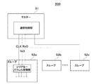
図5は、従来の全二重方式のシリアル通信システム500の構成を概略的に示すブロック図である。図5において、主制御部であるマスター51は制御対象装置全体を制御し、従制御部である複数のスレーブ52a,52b・・・52xは、例えば、制御対象装置のセンサ、モータの駆動、ASICのレジスタ設定等の各機能部としての各負荷部を制御する。マスター51及び各スレーブ52a,52b・・・52x間のデータ通信は、マスター51から各スレーブ52a,52b・・・52xに送信されるクロック信号と同期して行なわれる。なお、スレーブの数は装置の構成により異なる。
FIG. 5 is a block diagram schematically showing a configuration of a conventional full-duplex
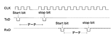
シリアル通信システム500の通信動作について、図6に示すタイミングチャートを用いて説明する。図6は、図5におけるマスター及びスレーブ間のデータ通信のタイミングチャートである。CLKは、例えばマスター51及びスレーブ52a間のクロック信号の波形を示し、TxD及びRxDは、例えば、それぞれマスター51からスレーブ52aに送信される信号のタイミング及びスレーブ52aからマスター51に送信される信号のタイミングを示す。マスター51はスレーブ52aに制御信号のシリアルデータを送信し、スレーブ52aは受信したシリアルデータをパラレルデータに変換し、変換したパラレルデータに基づいて各負荷部の制御を行なう。また、スレーブ52aはマスター51に各負荷部のステイタス通知等のシリアルデータを送信し、マスター51は受信したシリアルデータをパラレル変換して情報を取得する。図5に示したシリアル通信システム500によれば、マスター51と各スレーブ52a,52b・・・52xとの間の信号線の数は各2本で足りる。
The communication operation of the
ところで、最近の画像形成装置では、複写スピードの高速化、及び多機能化に伴い、各機能部間のデータ通信に必要な信号線の本数が増加する傾向にある。このような画像形成装置において、図5に示したシリアル通信システム500による通信制御を行なうことによって、信号線の本数の増加を抑制する試みがなされている。
しかしながら、図5に示す従来のシリアル通信システム500では、クロック信号はどのスレーブに対しても同じ周波数で設定されるため、各信号線から非常に大きなエネルギーの放射ノイズが放出されるという問題がある。この場合に、放射ノイズを公的機関による規格で制限された一定のレベル以下まで抑えるためには、フェライトコア、ビーズ等の放射ノイズ対策部品を設ける必要があり、余分なコストがかかることにもなる。
However, in the conventional
本発明の目的は、データ通信に伴う放射ノイズを低減することができる通信制御装置を提供することにある。 An object of the present invention is to provide a communication control equipment which can reduce the radiated noise caused by the data communication.
上記目的を達成するために、請求項1記載の通信制御装置は、主制御手段と、前記主制御手段からの信号に基づき負荷を制御する第1及び第2従制御手段と、前記第1及び第2従制御手段のそれぞれと前記主制御手段とがシリアル通信を行うための第1及び第2通信手段とを有し、前記主制御手段は、前記第1及び第2通信手段を用いて前記第1及び第2従制御手段のそれぞれと通信し、前記第1及び第2従制御手段のそれぞれとの通信結果に基づき、前記第1及び第2従制御手段のそれぞれとの通信で使用する第1周波数及び該第1周波数と異なる第2周波数を設定する設定手段と、前記設定手段によって設定された前記第1及び第2周波数のそれぞれに応じた第1及び第2クロック信号を生成する生成手段と、前記第1通信手段を用いて前記第1クロック信号に基づく通信を前記第1従制御手段と行い、前記第2通信手段を用いて前記第2クロック信号に基づく通信を前記第2従制御手段と行う通信制御手段とを有することを特徴とする。
To achieve the above object, a communication control apparatus according to
本発明によれば、各従制御手段に送信されるクロック信号は、各従制御手段の通信データ量に応じて変調されるので、放射ノイズのエネルギーを分散させることができ、これにより、データ通信に伴う放射ノイズを低減させることができる。 According to the present invention, the clock signal transmitted to each slave control means is modulated according to the amount of communication data of each slave control means, so that the energy of the radiation noise can be dispersed, thereby enabling data communication. The radiation noise accompanying with can be reduced.
以下、本発明の実施の形態について図面を参照しながら説明する。 Hereinafter, embodiments of the present invention will be described with reference to the drawings.
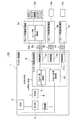
図1は、本発明の実施の形態に係る通信制御装置の構成を概略的に示すブロック図である。 FIG. 1 is a block diagram schematically showing a configuration of a communication control apparatus according to an embodiment of the present invention.
図1において、本通信制御装置100は、マスター制御部(主制御手段)1と、マスター制御部1に各チャネル2a,2b・・・2xを介して接続される各スレーブ用通信制御部(従制御手段)3a,3b・・・3xとから主として構成されている。マスター制御部1は制御対象装置全体を制御し、スレーブ用通信制御部3a,3b・・・3xは、マスター制御部1からの信号に基づいて制御対象装置の各機能部である負荷部を制御する。スレーブ用通信制御部の数、及びこれに対応するチャネルの数は、通信制御システム100の構成によって変動する。スレーブ用通信制御部3a,3b・・・3xは、通信制御装置100に付設される付属装置類に設けられた制御部であってもよい。
In FIG. 1, a
マスター制御部1は、CPU4と、ROM5と、RAM6と、発振器(クロック信号発生手段)7と、マスター用通信制御部8とを備える。CPU4はアドレスバスを介して、ROM5、RAM6、及びマスター用通信制御部8と接続され、データバスを介して、ROM5、RAM6、及びマスター用通信制御部8の後述するマスター用シリアル−パラレル変換部9と接続される。
The
マスター用通信制御部8は、マスター用シリアル−パラレル変換部9と、クロック信号変調部(周波数変調手段)10と、同期回路11a,11b・・・11xとを有する。マスター用シリアル−パラレル変換部9及びクロック信号変調部10は、それぞれ各同期回路11a,11b・・・11xと並列に接続されている。同期回路11a,11b・・・11xは、チャネル2a,2b・・・2xを介して、スレーブ用通信制御部3a,3b・・・3xと1対1の関係で接続されている。各スレーブ用通信制御部3a,3b・・・3xは、それぞれスレーブ用シリアル−パラレル変換部12a,12b・・・12x(12b以降は不図示)を有する。
The master
CPU4は、通信制御装置100全体の制御を行なうシステム制御部である。ROM5は、CPU4によって実行される通信制御システム100の一連の動作を行なうための制御プログラムを格納する。RAM6は、CPU4で処理するデータ等を一時的に格納する作業領域として用いられる。発振器7は、CPU4からの命令に基づいて、マスター制御部1の動作の基準となるクロック信号を発生させ、発生したクロック信号を初期クロック信号としてクロック信号変調部10に出力する。
The
クロック信号変調部10は、CPU4の命令に基づいて、発振器7から出力された初期クロック信号の周波数を変調し、例えば、周波数が逓倍化されたクロック信号(以下、「変調クロック信号」という。)を生成する。逓倍化とは、周波数をN倍化することをいい、Nは整数である。また、クロック信号変調部10は、生成した変調クロック信号を、各同期回路11a,11b・・・11xを介して各スレーブ用通信制御部3a,3b・・・3xに送信する。各同期回路11a,11b・・・11xは、マスター制御部1と各スレーブ用通信制御部3a,3b・・・3xとの間で通信される信号を、各変調クロック信号と同期させる。
The clock
マスター用シリアル−パラレル変換部9は、CPU4から送信された制御信号のパラレルデータをシリアルデータに変換し、このシリアルデータを、各同期回路11a,11b・・・11xを介してスレーブ用通信制御部3a,3b・・・3xに送信する。制御信号のシリアルデータを受信した各スレーブ用通信制御部3a,3b・・・3xは、各スレーブ用シリアル−パラレル変換部12a,12b・・・12xによってシリアルデータをパラレルデータに変換する。そして、各スレーブ用通信制御部3a,3b・・・3xは、変換されたパラレルデータに基づいて、制御対象装置、例えば、画像形成装置のASIC、モータ駆動部、センサ等の負荷部13a,13b・・・13xを制御する。
The master serial-parallel converter 9 converts the parallel data of the control signal transmitted from the
また、各スレーブ用通信制御部3a,3b・・・3xは、制御対象装置、例えば、画像形成装置において収集されたセンサの信号を各スレーブ用シリアル−パラレル変換部12a,12b・・・12xによってシリアルデータに変換し、マスター用通信制御部8に送信する。シリアルデータを受信したマスター用通信制御部8は、マスター用シリアル−パラレル変換部9によってシリアルデータをパラレルデータに変換し、このパラレルデータをCPU4に送信する。
Each of the slave
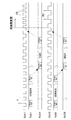
次に、通信制御装置100の通信制御動作について、図2を用いながら詳述する。図2は、図1に示した通信制御装置における、マスター制御部1がチャネル2a,2bを介してスレーブ用通信制御部3a,3bを制御する場合のデータ通信のタイミングチャートである。CLK1、TxD1及びRxD1はチャネル2aのタイミングチャートを、CLK2、TxD2及びRxD2はチャネル2bのタイミングチャートを示す。CLK1はマスター制御部1及びスレーブ用通信制御部3a間のクロック信号の波形を示し、TxD1及びRxDは、それぞれマスター制御部1からスレーブ用通信制御部3aに送信される信号のタイミング及びスレーブ用通信制御部3aからマスター制御部1に送信される信号のタイミングを示す。同様に、CLK2はマスター制御部1及びスレーブ用通信制御部3b間のクロック信号の波形を示し、TxD2及びRxD2は、それぞれマスター制御部1からスレーブ用通信制御部3bに送信される信号のタイミング及びスレーブ用通信制御部3bからマスター制御部1に送信される信号のタイミングを示す。
Next, the communication control operation of the
図2において、通信制御動作開始直後の通信制御装置100の各チャネル2a,2bには、発振器7によって発生された周波数fの初期クロック信号が送信されている。通信制御装置100において、まず、CPU4は、マスター用通信制御部8に各スレーブ用通信制御部3a,3bに対するID問合せ命令を送信する。ID問合せ命令を受信したマスター用通信制御部8は、マスター用シリアル−パラレル変換部9によってID問い合わせ命令をシリアルデータに変換し、このシリアルデータを各スレーブ用通信制御部3a,3bに向けて送信する。各スレーブ用通信制御部3a,3bに向けて送信されたシリアルデータは、各同期回路11a,11bを介することによって初期クロック信号と同期し、各チャネル2a,2bを介して各スレーブ用通信制御部3a,3bに送信される。
In FIG. 2, the initial clock signal of the frequency f generated by the
シリアルデータを受信した各スレーブ用通信制御部3a,3bは、スレーブ用シリアル−パラレル変換部12a,12bによってシリアルデータをパラレルデータに変換して、CPU4からのID問合せ信号を認識する。ID問合せ信号を認識した各スレーブ用通信制御部3a,3bは、それぞれID「00」,「01」を各スレーブ用シリアル−パラレル変換部12a,12bによってシリアルデータに変換し、このシリアルデータをマスター用通信制御部8に向けて送信する。ここで、IDは、各スレーブ用通信制御部3a,3bが通信処理可能な通信データ量に応じて各スレーブ用通信制御部3a,3bに予め割り当てられたのものであり、各スレーブ用通信制御部3a,3bの固有のものである。
Each of the slave
各IDを受信したマスター用通信制御部8は、マスター用シリアル−パラレル変換部9によってシリアルデータをパラレルデータに変換し、このパラレルデータをCPU4に送信する。パラレルデータを受信したCPU4は各IDを認識し、ROM5に格納されている、例えば、図3に示すテーブルのような情報を読み出して、各IDに対応したクロック設定値を抽出する。
Receiving each ID, the master
図3は、IDとクロック設定値(クロック信号の周波数)との対応関係を示す図であり、ROM5に格納された情報を例示するものである。図3において、ID「00」を送信したスレーブ用通信制御部3aに対するクロック設定値は「f+x%」であり、ID「01」を送信したスレーブ用通信制御部3bに対するクロック設定値は「f−y%」である。ここで、「f+x%」、「f−y%」及び「f±m%」は、周波数fの逓倍である。
FIG. 3 is a diagram illustrating a correspondence relationship between the ID and the clock setting value (clock signal frequency), and illustrates information stored in the
ROM5から各クロック設定値を抽出したCPU4は、クロック信号変調部10に、各クロック設定値に基づいて各スレーブ用通信制御部3a,3bに対するクロック信号をそれぞれ変調させる変調命令を送信する。変調命令を受信したクロック信号変調部10は、「f+x%」のクロック設定値に基づいて初期クロック信号の周波数fをf+x%であるf2に変調し、周波数f2の変調クロック信号をスレーブ用通信制御部3aに送信する。また、クロック信号変調部10は、「f−y%」のクロック設定値に基づいて初期クロック信号の周波数fをf−y%であるf1に変調し、周波数f1の変調クロック信号をスレーブ用通信制御部3bに送信する。その後、マスター制御部1と各スレーブ用通信制御部3a,3bとの間で種々のデータ通信が行なわれる。
CPU4 which extracted each clock setting value from ROM5 transmits the modulation command which modulates the clock signal with respect to each slave
上述の通信制御装置100のデータ通信時における放射ノイズの特性を図4に示す。図4において、縦軸は通信制御装置100から放出される放射ノイズのエネルギーを示し、横軸は通信制御装置100におけるクロック信号の周波数を示す。通信制御装置100の放射ノイズの特性を点線で示し、比較例として、全てのチャネルに同じ周波数のクロック信号を送信する従来の通信制御装置の放射ノイズの特性を実線で示す。
FIG. 4 shows the characteristics of radiation noise during the data communication of the
従来の通信制御装置では、各チャネル2a,2bに周波数fのクロック信号が送信される。このため、各チャネル2a,2bでのデータ通信の際、図4中に実線で示されるように、共振により周波数f(2逓倍の2f,3逓倍の3f・・・)のエネルギーの高い放射ノイズが放出されることになる。
In the conventional communication control apparatus, a clock signal having a frequency f is transmitted to each of the
一方、上述の通信制御装置100では、各チャネル2a,2bにそれぞれ周波数f2のクロック信号、周波数f1のクロック信号が送信される。このため、各チャネル2a,2bでのデータ通信の際、図4中に点線で示されるように、周波数f1(2逓倍の2f1,3逓倍の3f1・・・)及び周波数f2(2逓倍の2f2,3逓倍の3f2・・・)のエネルギーの低い放射ノイズが放出される。このように、通信制御装置100によれば、放射ノイズのエネルギーが分散されるので、データ通信に伴う各放射ノイズのエネルギーが低減される。
On the other hand, in the
以上のように、本実施の形態に係る通信制御装置100によれば、マスター制御部1と各スレーブ用通信制御部3a,3b・・・3xとの間の各クロック信号は、各スレーブ用通信制御部3a,3b・・・3xの通信データ量に応じて変調される。したがって、各チャネル2a,2b・・・2xからの放射ノイズのエネルギーを分散させることができ、通信制御装置100によって通信制御を行なう、例えば、画像形成装置の放射ノイズを低減させることができる。
As described above, according to the
また、本実施の形態では、各スレーブ用通信制御部3a,3b・・・3xの通信データ量に応じて、各スレーブ用通信制御部3a,3b・・・3xに予め割り当てられた各IDに基づいて変調クロック信号の周波数が設定される。これは、スレーブ用通信制御部3a,3b・・・3xが標準装備のものではなく、通信方式が未知な装置として後から付設されるような場合に、特に有効である。一方、標準装備のスレーブ用通信制御部3a,3b・・・3xであれば、IDのかわりに通信データ量を示すデータをマスター用通信制御部8に送信してもよい。この場合、ROM5には、通信データ量とクロック設定値とが直接対応付けられて格納される。
Further, in the present embodiment, according to the communication data amount of each slave
さらに、本実施の形態に係る通信制御装置100において、スレーブ通信制御装置の通信データ量が大きくなるほど、対応するスレーブ通信制御装置に送信される変調クロック信号の周波数が大きくなるようにクロック設定値を設定してもよい。例えば、スレーブ用通信制御部3a,3b,3cにおいて、各通信データ量の大きさが3a>3b>3cの場合に、各スレーブ用通信制御部に送信される変調クロック信号の周波数の大きさが3a>3b>3cとなるように変調する。これにより、大容量のデータ通信を行うチャネル2aの通信速度の低下が抑制されるとともに、各チャネル2a,2b,2c間での通信速度のばらつきを低減することができる。
Furthermore, in
また、本実施の形態に係る通信制御装置100において、スレーブ通信制御装置の通信データ量が小さくなるほど、対応するスレーブ通信制御装置に送信される変調クロック信号の周波数が小さくなるようにクロック設定値を設定してもよい。
In
本発明は、上述した実施の形態の機能を実現するソフトウェアのプログラムコードを記録した記憶媒体を、システム或いは装置に供給し、そのシステム或いは装置のコンピュータ(またはCPUやMPU等)が記憶媒体に格納されたプログラムコードを読み出し実行することによっても実現できる。 The present invention supplies a storage medium storing software program codes for realizing the functions of the above-described embodiments to a system or apparatus, and the computer (or CPU, MPU, etc.) of the system or apparatus stores the storage medium in the storage medium. This can also be realized by reading out and executing the program code.
この場合、記憶媒体から読み出されたプログラムコード自体が上述した実施の形態の機能を実現することになり、そのプログラムコード及び該プログラムコードを記憶した記憶媒体は本発明を構成することになる。 In this case, the program code itself read from the storage medium realizes the functions of the above-described embodiment, and the program code and the storage medium storing the program code constitute the present invention.
また、プログラムコードを供給するための、コンピュータで読み取り可能な記憶媒体としては、例えば、フロッピー(登録商標)ディスク、ハードディスク、光磁気ディスク、CD−ROM、CD−R、CD−RWなどの光ディスク、DVD−ROM、DVD−RAM、DVD−RW、DVD+RW、磁気テープ、不揮発性のメモリカード、ROM等を用いることができる。または、プログラムコードを、ネットワークを介してダウンロードしてもよい。 Examples of the computer-readable storage medium for supplying the program code include a floppy (registered trademark) disk, a hard disk, a magneto-optical disk, an optical disk such as a CD-ROM, a CD-R, and a CD-RW, A DVD-ROM, a DVD-RAM, a DVD-RW, a DVD + RW, a magnetic tape, a nonvolatile memory card, a ROM, or the like can be used. Alternatively, the program code may be downloaded via a network.
また、コンピュータが読み出したプログラムコードを実行するだけではなく、そのプログラムコードの指示に基づき、コンピュータ上で稼動しているOS(オペレーティングシステム)等が実際の処理の一部または全部を行い、その処理によって上述した実施の形態の機能が実現される場合も含まれる。 In addition to executing the program code read by the computer, an OS (operating system) operating on the computer performs part or all of the actual processing based on an instruction of the program code, and the processing This includes the case where the functions of the above-described embodiment are realized.
更に、記憶媒体から読み出されたプログラムコードが、コンピュータに挿入された機能拡張ボードやコンピュータに接続された機能拡張ユニットに備わるメモリに書き込まれた後、そのプログラムコードの指示に基づき、その拡張機能を拡張ボードや拡張ユニットに備わるCPU等が実際の処理の一部または全部を行い、その処理によって上述した実施の形態の機能が実現される場合も含まれる。 Further, after the program code read from the storage medium is written in a memory provided in a function expansion board inserted into the computer or a function expansion unit connected to the computer, the expanded function is based on the instruction of the program code. This includes a case where a CPU or the like provided on the expansion board or the expansion unit performs part or all of the actual processing and the functions of the above-described embodiments are realized by the processing.
1 マスター制御部
3a,3b,3x スレーブ用通信制御部
4 CPU
7 発振器
8 マスター用通信制御部
10 クロック信号変調部
100 通信制御システム
1
7
Claims (7)
前記主制御手段からの信号に基づき負荷を制御する第1及び第2従制御手段と、
前記第1及び第2従制御手段のそれぞれと前記主制御手段とがシリアル通信を行うための第1及び第2通信手段とを有し、
前記主制御手段は、
前記第1及び第2通信手段を用いて前記第1及び第2従制御手段のそれぞれと通信し、前記第1及び第2従制御手段のそれぞれとの通信結果に基づき、前記第1及び第2従制御手段のそれぞれとの通信で使用する第1周波数及び該第1周波数と異なる第2周波数を設定する設定手段と、
前記設定手段によって設定された前記第1及び第2周波数のそれぞれに応じた第1及び第2クロック信号を生成する生成手段と、
前記第1通信手段を用いて前記第1クロック信号に基づく通信を前記第1従制御手段と行い、前記第2通信手段を用いて前記第2クロック信号に基づく通信を前記第2従制御手段と行う通信制御手段とを有することを特徴とする通信制御装置。 Main control means;
First and second slave control means for controlling a load based on a signal from the main control means ;
Each of the first and second slave control means and the main control means have first and second communication means for performing serial communication,
The main control means includes
Communicating with each of the first and second slave control means using the first and second communication means, and based on the result of communication with each of the first and second slave control means, the first and second slave means. Setting means for setting a first frequency used in communication with each of the slave control means and a second frequency different from the first frequency;
Generating means for generating first and second clock signals corresponding to each of the first and second frequencies set by the setting means;
Communication based on the first clock signal is performed with the first slave control unit using the first communication unit, and communication based on the second clock signal is performed with the second slave control unit using the second communication unit. A communication control device comprising: a communication control means for performing .
前記第1及び第2通信手段を用いて前記第1及び第2従制御手段のそれぞれと通信し、前記第1及び第2従制御手段のそれぞれの識別情報を取得し、Communicating with each of the first and second slave control means using the first and second communication means to obtain identification information of the first and second slave control means;
前記第1及び第2従制御手段のそれぞれの識別情報に基づき、前記第1及び第2周波数を設定することを特徴とする請求項1乃至4のいずれか1項に記載の通信制御装置。5. The communication control device according to claim 1, wherein the first and second frequencies are set based on identification information of each of the first and second slave control units.
前記第1及び第2通信手段を用いて前記第1及び第2従制御手段のそれぞれと通信し、前記第1及び第2従制御手段のそれぞれの通信データ量を示すデータを取得し、Communicating with each of the first and second slave control means using the first and second communication means, obtaining data indicating the respective communication data amounts of the first and second slave control means,
前記第1及び第2従制御手段のそれぞれの通信データ量を示すデータに基づき、前記第1及び第2周波数を設定することを特徴とする請求項1乃至3のいずれか1項に記載の通信制御装置。The communication according to any one of claims 1 to 3, wherein the first and second frequencies are set based on data indicating respective communication data amounts of the first and second slave control means. Control device.
Priority Applications (1)
| Application Number | Priority Date | Filing Date | Title |
|---|---|---|---|
| JP2008159156A JP5224924B2 (en) | 2008-06-18 | 2008-06-18 | Communication control device |
Applications Claiming Priority (1)
| Application Number | Priority Date | Filing Date | Title |
|---|---|---|---|
| JP2008159156A JP5224924B2 (en) | 2008-06-18 | 2008-06-18 | Communication control device |
Publications (3)
| Publication Number | Publication Date |
|---|---|
| JP2010004123A JP2010004123A (en) | 2010-01-07 |
| JP2010004123A5 JP2010004123A5 (en) | 2011-08-04 |
| JP5224924B2 true JP5224924B2 (en) | 2013-07-03 |
Family
ID=41585504
Family Applications (1)
| Application Number | Title | Priority Date | Filing Date |
|---|---|---|---|
| JP2008159156A Expired - Fee Related JP5224924B2 (en) | 2008-06-18 | 2008-06-18 | Communication control device |
Country Status (1)
| Country | Link |
|---|---|
| JP (1) | JP5224924B2 (en) |
Family Cites Families (8)
| Publication number | Priority date | Publication date | Assignee | Title |
|---|---|---|---|---|
| JPS57183154A (en) * | 1981-05-06 | 1982-11-11 | Toshiba Corp | Multispeed transmission system |
| JPH02308356A (en) * | 1989-05-24 | 1990-12-21 | Nec Corp | Parallel processor |
| JP3323719B2 (en) * | 1995-12-14 | 2002-09-09 | 富士通株式会社 | Star communication device |
| JP4266477B2 (en) * | 2000-02-25 | 2009-05-20 | キヤノン株式会社 | Information processing apparatus and control method thereof |
| JP2001320390A (en) * | 2000-05-11 | 2001-11-16 | Matsushita Electric Ind Co Ltd | Serial bus control device and control method |
| JP2006106331A (en) * | 2004-10-05 | 2006-04-20 | Sharp Corp | Load driving device and LED display device including the same |
| JP2006293138A (en) * | 2005-04-13 | 2006-10-26 | Canon Inc | Image forming apparatus |
| JP5408844B2 (en) * | 2006-07-04 | 2014-02-05 | キヤノン株式会社 | Bus system |
-
2008
- 2008-06-18 JP JP2008159156A patent/JP5224924B2/en not_active Expired - Fee Related
Also Published As
| Publication number | Publication date |
|---|---|
| JP2010004123A (en) | 2010-01-07 |
Similar Documents
| Publication | Publication Date | Title |
|---|---|---|
| US9141890B2 (en) | Data processing apparatus, data processing method, data processing program for implementing the method, and image processing apparatus | |
| JP2013203003A (en) | Printer | |
| JP4550059B2 (en) | Wireless tag reading system, wireless tag reader, and wireless tag | |
| JP5245561B2 (en) | Image processing apparatus and energy saving return method | |
| JP5224924B2 (en) | Communication control device | |
| JP2006343815A (en) | COMMUNICATION DEVICE, COMMUNICATION METHOD, COMMUNICATION SYSTEM | |
| JP6013440B2 (en) | Phase difference compensation method and apparatus for clock signals between chips in a multi-chip system | |
| JP4933393B2 (en) | Communication apparatus and communication method thereof | |
| JP2004064616A (en) | Baud rate setting method, baud rate setting program, readable recording medium, communication system and communication method | |
| JP2013058018A (en) | Remote access system, electronic equipment and remote access processing method | |
| JP7677049B2 (en) | COMMUNICATION DEVICE, COMMUNICATION SYSTEM, AND COMMUNICATION METHOD | |
| US8803714B2 (en) | Transmitting device and receiving device | |
| US20070134961A1 (en) | Apparatus and method for interfacing XFP optical transceiver with 300-pin MSA optical transponder | |
| JP2005512439A (en) | System with clocked interface | |
| KR102261924B1 (en) | Data transmission node device capable of determining a communication scheduling method for performing communication with a data receiving node device in a multi-hop relay cooperative communication network and operating method thereof | |
| JP2003163653A (en) | Serial data communication method | |
| US20250227635A1 (en) | Phase offset compensation device and method | |
| JP6131670B2 (en) | Wireless base station, wireless control device, wireless device, and delay amount measuring method | |
| JP5458193B2 (en) | Electronic device and remote access processing method | |
| JP7367346B2 (en) | Equipment, data generation program, and data generation method | |
| JP2003110565A (en) | Communication system, transmitter, communication method, communication program, and computer readable recording medium recording the same program | |
| JP2005217653A (en) | Electronics | |
| KR20240044310A (en) | Apparatus and method for phase offset compensation | |
| JP2011076403A (en) | Motherboard, method and system for supplying power to expanded board of the same | |
| KR20250020111A (en) | Wireless jumper coupler |
Legal Events
| Date | Code | Title | Description |
|---|---|---|---|
| A521 | Written amendment |
Free format text: JAPANESE INTERMEDIATE CODE: A523 Effective date: 20110617 |
|
| A621 | Written request for application examination |
Free format text: JAPANESE INTERMEDIATE CODE: A621 Effective date: 20110617 |
|
| A977 | Report on retrieval |
Free format text: JAPANESE INTERMEDIATE CODE: A971007 Effective date: 20120524 |
|
| A131 | Notification of reasons for refusal |
Free format text: JAPANESE INTERMEDIATE CODE: A131 Effective date: 20120605 |
|
| A521 | Written amendment |
Free format text: JAPANESE INTERMEDIATE CODE: A523 Effective date: 20120806 |
|
| A131 | Notification of reasons for refusal |
Free format text: JAPANESE INTERMEDIATE CODE: A131 Effective date: 20121002 |
|
| TRDD | Decision of grant or rejection written | ||
| A01 | Written decision to grant a patent or to grant a registration (utility model) |
Free format text: JAPANESE INTERMEDIATE CODE: A01 Effective date: 20130212 |
|
| A61 | First payment of annual fees (during grant procedure) |
Free format text: JAPANESE INTERMEDIATE CODE: A61 Effective date: 20130312 |
|
| FPAY | Renewal fee payment (event date is renewal date of database) |
Free format text: PAYMENT UNTIL: 20160322 Year of fee payment: 3 |
|
| LAPS | Cancellation because of no payment of annual fees |