JP5222829B2 - Work machine monitor fixing structure - Google Patents
Work machine monitor fixing structure Download PDFInfo
- Publication number
- JP5222829B2 JP5222829B2 JP2009260867A JP2009260867A JP5222829B2 JP 5222829 B2 JP5222829 B2 JP 5222829B2 JP 2009260867 A JP2009260867 A JP 2009260867A JP 2009260867 A JP2009260867 A JP 2009260867A JP 5222829 B2 JP5222829 B2 JP 5222829B2
- Authority
- JP
- Japan
- Prior art keywords
- monitor
- fixing structure
- monitor device
- cylinder part
- fixed
- Prior art date
- Legal status (The legal status is an assumption and is not a legal conclusion. Google has not performed a legal analysis and makes no representation as to the accuracy of the status listed.)
- Active
Links
- 238000006073 displacement reaction Methods 0.000 description 2
- 230000000694 effects Effects 0.000 description 2
- 239000010720 hydraulic oil Substances 0.000 description 2
- 238000003780 insertion Methods 0.000 description 2
- 230000037431 insertion Effects 0.000 description 2
- 230000007246 mechanism Effects 0.000 description 2
- 238000012806 monitoring device Methods 0.000 description 2
- 238000000926 separation method Methods 0.000 description 2
- 101700004678 SLIT3 Proteins 0.000 description 1
- 102100027340 Slit homolog 2 protein Human genes 0.000 description 1
- 101710133576 Slit homolog 2 protein Proteins 0.000 description 1
- 102100027339 Slit homolog 3 protein Human genes 0.000 description 1
- 230000009471 action Effects 0.000 description 1
- 230000008901 benefit Effects 0.000 description 1
- 238000012790 confirmation Methods 0.000 description 1
- 239000002826 coolant Substances 0.000 description 1
- 238000012423 maintenance Methods 0.000 description 1
- 239000002184 metal Substances 0.000 description 1
- 238000000034 method Methods 0.000 description 1
- 238000012986 modification Methods 0.000 description 1
- 230000004048 modification Effects 0.000 description 1
- 239000010705 motor oil Substances 0.000 description 1
- 239000011347 resin Substances 0.000 description 1
- 229920005989 resin Polymers 0.000 description 1
- 230000008961 swelling Effects 0.000 description 1
Images
Landscapes
- Component Parts Of Construction Machinery (AREA)
- Instrument Panels (AREA)
Description
本発明は、作業機械のキャブの内部にモニタ装置を固定するためのモニタ固定構造に関する。 The present invention relates to a monitor fixing structure for fixing a monitor device inside a cab of a work machine.
油圧ショベルを始めとする作業機械のキャブ(運転室)の内部には、オペレータ(作業者)に必要な機械情報を表示するモニタ装置が設けられている。モニタ装置で表示される機械情報は、作動油量やエンジンオイル量,エンジン冷却水量をはじめとして、バッテリ電圧,エンジン回転数,作動油温度,ポンプ吐出圧等と多岐にわたる。一般に、モニタ装置はキャブ内に着座したオペレータの視界の妨げにならない位置に固定される。例えば、特許文献1の図4には、オペレータの着座シートから見て、キャブの前面における右側端部にモニタ装置(表示器)を設けた構造が示されている。
A monitor device for displaying machine information necessary for an operator (operator) is provided inside a cab (operator's cab) of a work machine such as a hydraulic excavator. The machine information displayed on the monitor device varies widely, including the amount of hydraulic oil, the amount of engine oil, the amount of engine coolant, battery voltage, engine speed, hydraulic oil temperature, pump discharge pressure, and the like. Generally, the monitor device is fixed at a position that does not interfere with the view of the operator seated in the cab. For example, FIG. 4 of
ところで、表示画面の視認性を向上させるべく、オペレータに対する角度を調整する機構を備えたモニタ装置が知られている。例えば、特許文献2の第2図には、モニタパネル部が上下方向に揺動可能に設けられたモニタパネル部とその基部に設けられた位置決め機構とを備えたモニタ装置が示されている。この技術では、モニタパネル部の揺動軸に対してボール及びボルトの先端を押し付けることによって揺動を止め、所望の位置でのモニタ装置の角度固定を実現している。
By the way, in order to improve the visibility of the display screen, a monitor device having a mechanism for adjusting an angle with respect to an operator is known. For example, FIG. 2 of
しかしながら、特許文献2に記載のようにボルトの締結によって回転揺動を止める構造では、角度調整の作業から締結作業を完了させるまでの間、モニタ装置が動かないように支持しておく必要があり手間がかかるうえ、ボルトの締結力が不十分な場合にはモニタ装置の固定が緩みやすく、確実に固定することができない場合があるという課題がある。
また、たとえモニタ装置の角度を調整した直後には堅固に固定されていたとしても、長時間が経過した後にも同様に堅固に固定されているとは限らない。特に、車体振動のような外力が長時間作用しやすい作業機械では、時間経過とともにボルトが緩む場合も考えられる。一方、ボルトの緩みは目視で確認することが難しいため、締結具を用いて定期的に締結力を確認する必要があり、メンテナンスが煩雑であるという課題もある。
However, in the structure in which the rotation is stopped by fastening the bolt as described in
Further, even if the monitor device is firmly fixed immediately after the angle of the monitor device is adjusted, the monitor device is not always firmly fixed even after a long time has passed. In particular, in a work machine in which an external force such as vehicle body vibration is likely to act for a long time, the bolt may be loosened over time. On the other hand, since it is difficult to visually check the looseness of the bolt, it is necessary to periodically check the fastening force using a fastener, and there is a problem that maintenance is complicated.
本発明はこのような課題に鑑みてなされたもので、簡素な構成で、角度調整を容易かつ確実に行うことができる作業機械のモニタ固定構造を提供することを目的とする。 The present invention has been made in view of such a problem, and an object of the present invention is to provide a monitor fixing structure for a work machine that can easily and surely adjust the angle with a simple configuration.
上記目的を達成するため、請求項1記載の本発明の作業機械のモニタ固定構造は、作業機械のキャブの内部にモニタ装置を固定するためのモニタ固定構造であって、該キャブに固定され、円筒状に形成された第一筒部と、該モニタ装置に固定され、該第一筒部に嵌合する円筒状に形成された第二筒部と、該第一筒部と該第二筒部との嵌合部位に外嵌され、該嵌合部位を外側から締め付けて固定するクランプ装置と、該第一筒部及び該第二筒部の何れか一方に穿孔され、周方向に延設されたスリット孔と、該第一筒部及び該第二筒部の何れか他方において上記何れか一方へ向けて突設され、該第一筒部及び該第二筒部の嵌合時に該スリット孔の内側に配設される突起部とを備えたことを特徴としている。
In order to achieve the above object, a monitor fixing structure for a work machine according to
また、請求項2記載の本発明の作業機械のモニタ固定構造は、請求項1記載の構成に加え、該クランプ装置が、環の一部を切断されてなる断面C字型に形成され、該嵌合部位に外嵌された欠環部と、該欠環部の両端から延設され、互いに離隔して対向配置された一対の対向部と、該一対の対向部間に跨って架け渡され、該一対の対向部の一方に係止された連結棒と、該連結棒に対して回動自在に支持されたレバー部と、該レバー部の基端において該レバー部と一体形成され、該一対の対向部の他方を該一方へ向けて押圧するとともに、該一対の対向部の他方との接触位置と該レバー部の回動中心との距離を該レバー部の回動角度に応じて変化させるカム部とを有することを特徴としている。 According to a second aspect of the present invention, there is provided a monitor fixing structure for a work machine according to the present invention, in addition to the structure of the first aspect, wherein the clamp device is formed in a C-shaped cross section formed by cutting a part of the ring. A missing ring part that is externally fitted to the fitting part, a pair of opposed parts that are extended from both ends of the missing ring part and are arranged opposite to each other, and spanned between the pair of opposed parts. A connecting rod locked to one of the pair of opposing portions, a lever portion supported rotatably with respect to the connecting rod, and a lever portion integrally formed with the lever portion at the base end of the lever portion, While pressing the other of the pair of facing portions toward the one, the distance between the contact position of the pair of facing portions with the other and the rotation center of the lever portion is changed according to the rotation angle of the lever portion. And having a cam portion to be operated.
また、請求項3記載の本発明の作業機械のモニタ固定構造は、請求項2記載の構成に加え、該第二筒部が、該キャブの内部に配置される座席に対して該モニタ装置の裏側に固定され、該レバー部が、該クランプ装置による該嵌合部位の固定時に、該モニタ装置の裏側に収容されて該座席側からの視認範囲外に配置され、かつ、該クランプ装置による該嵌合部位の固定の解除時に、該モニタ装置の裏側からはみ出して該座席側からの視認範囲内に配置されることを特徴としている。 According to a third aspect of the present invention, there is provided a monitor fixing structure for a work machine according to the present invention. Fixed to the back side, and when the fitting portion is fixed by the clamp device, the lever portion is accommodated on the back side of the monitor device and disposed outside the viewing range from the seat side, and the clamp device At the time of releasing the fixing of the fitting part, it is characterized in that it protrudes from the back side of the monitor device and is disposed within the visible range from the seat side.
本発明の作業機械のモニタ固定構造(請求項1)によれば、キャブに対するモニタ装置の筒軸回りの角度を容易に調整することができる。また、スリット孔の延設長さに応じて角度の調整範囲を設定することができる。
また、本発明の作業機械のモニタ固定構造(請求項2)によれば、レバー部を傾動させるという簡単な操作によりクランプ装置の締め付け及びその解除操作をワンタッチで行うことができ、モニタ装置の角度調整の操作性を向上させることができる。
According to the monitor fixing structure for a working machine of the present invention (Claim 1), the angle around the cylinder axis of the monitor device with respect to the cab can be easily adjusted. Further, the angle adjustment range can be set according to the extension length of the slit hole.
Further, according to the monitor fixing structure of the working machine of the present invention (Claim 2), the clamping device can be tightened and released by a simple operation of tilting the lever portion, and the angle of the monitoring device can be adjusted. The operability of adjustment can be improved.
また、本発明の作業機械のモニタ固定構造(請求項3)によれば、クランプ装置の締め付け忘れの確認が容易となり、利便性を向上させることができる。また、クランプ装置の固定時にはレバー部をモニタ装置の裏側に隠すことができ、良好な視界を確保することができる。 In addition, according to the monitor fixing structure for a working machine of the present invention (claim 3), confirmation of forgetting to tighten the clamp device is facilitated, and convenience can be improved. Further, when the clamp device is fixed, the lever portion can be hidden behind the monitor device, so that a good field of view can be secured.
以下、図面により、本発明の実施の形態について説明する。
[1.構成]
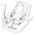
本キャブ構造が適用された油圧ショベルのキャブ10を図1に示す。キャブ10内には、オペレータが着席するシート7(運転席)が設けられ、その右前方にモニタ装置6が設置される。モニタ装置6は、その表示画面をシート7に着座するオペレータ側へ向けて配置され、キャブ10の構造体(例えば、ピラーやキャブフロア等)に対して固定される。
Hereinafter, embodiments of the present invention will be described with reference to the drawings.
[1. Constitution]
A
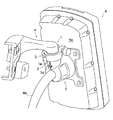
図2に示すように、モニタ装置6の裏面6aには第一固定具4及び第二固定具5が設けられる。本実施形態のモニタ固定構造は、金属製又は樹脂製の第一固定具4,第二固定具5及びクランプ装置3を備えて構成される。
第一固定具4はキャブ10に固定された部材であり、第二固定具5はモニタ装置6に固定された部材である。また、第二固定具5にはモニタ装置6に接続されるケーブル6bが内挿され、モニタ装置6の裏面6aとケーブル6bとの接合部を覆うように第二固定具5が固定される。第一固定具4が第二固定具5に対して内嵌され、この嵌合部位の外側にクランプ装置3が外嵌される。
As shown in FIG. 2, the first fixture 4 and the
The first fixture 4 is a member fixed to the
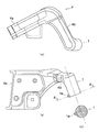
図3(a),(b)に示すように、第一固定具4は、キャブ10に対する固定面となる第一固定部4aと、その一側から延出する第一延出部4bを有する。また、第一延出部4bの先端には、円筒状の第一筒部1が形成される。第一筒部1には、図3(c)に示すように、筒面から外方へ向けて突起部1aが突設する。
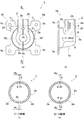
図4(a)に示すように、第二固定具5は左右に分割されて構成されており、すなわち図中の右側に配置された右ブラケット5aと、図中の左側に配置された左ブラケット5bとを備える。右ブラケット5a及び左ブラケット5bは互いに鏡像の関係となる形状に形成され、所定の間隙を空けて対向配置された状態でモニタ装置6に固定される。ここでは、右ブラケット5aと左ブラケット5bとが向かい合う面(対向面8)側から見た右ブラケット5aの側面を図4(b)に示し、右ブラケット5aの構造を詳述する。なお、対向面8は平面である。また、左ブラケット5bは右ブラケット5aの面対称形状であり、対向面8が平行となるように対向配置される。
As shown in FIGS. 3A and 3B, the first fixture 4 includes a
As shown in FIG. 4 (a), the
右ブラケット5aは、モニタ装置6に対する固定面となる第二固定部5cと、その固定面から膨出する膨出部5dとを有する。膨出部5dの中央には、中空半円柱状の貫通穴5eが形成される。右ブラケット5a及び左ブラケット5bのそれぞれの貫通穴5eは、互いに円柱面の内側が向かい合うように並置されて、ケーブル6bが内挿される円柱状の空洞を形成する。
The
また、膨出部5dに隣接するその上部には、中空半円柱状の嵌合部2aが膨出部5dと一体に設けられる。右ブラケット5a及び左ブラケット5bのそれぞれの嵌合部2aは、互いに内筒面2b側が向かい合うように並置されて、第一筒部1と嵌合する中空円筒状の第二筒部2を形成する。
本実施形態では、第一筒部1の筒軸と内筒面2bによって形成される中空円柱の筒軸とが一致するように、第一筒部1が第二筒部2に対して嵌め込まれる。なお、図4(b)に示すように、この筒軸はケーブル6bが内挿される方向に対して直交する。この例では、第一筒部1と第二筒部2との嵌合方向がモニタ装置6の裏面に対して略平行となり、ケーブル6bの内挿方向がモニタ装置6の裏面に対して略垂直となる。
A hollow semi-cylindrical
In this embodiment, the
図4(a)〜(d)に示すように、右ブラケット5a及び左ブラケット5b間には、所定の幅W0の間隙2cが設けられる。間隙2cは、第二筒部2をなす嵌合部2a,第二固定部5c及び膨出部5dの全てに渡って設けられ、右ブラケット5a及び左ブラケット5bの離接方向への相対変位を許容する。また、第二筒部2における間隙2cの延設方向はその筒軸と平行となり、筒面の縮径方向への変形が許容される。なお、右ブラケット5a及び左ブラケット5bのそれぞれの対向面8の間の距離が間隙2cの幅寸法W0である。したがって、幅寸法W0は右ブラケット5a及び左ブラケット5bをモニタ装置6に固定する位置に応じて規定される。
As shown in FIGS. 4A to 4D, a
図4(a)に示すように、第二筒部2をなす嵌合部2aには、右ブラケット5a及び左ブラケット5bをモニタ装置6に固定した状態において、その外側筒面と内側筒面(すなわち内筒面2b)との間を連通するスリット孔2dが設けられる。スリット孔2dは、第二筒部2の外側筒面における周方向に延設される。第一筒部1と第二筒部2との嵌合時に、第一筒部1の突起部1aは第二筒部2のスリット孔2dの内側に配設される。これらの突起部1a及びスリット孔2dにより、第二筒部2に対する第一筒部1の回動角度範囲が規定される。
As shown in FIG. 4 (a), the
また、スリット孔2dよりも第二筒部2の上端部側には、間隙2cよりも幅の広い縦スリット2eが設けられる。図4(c)に示すように、縦スリット2eの幅寸法はW1(W1>W0)ある。縦スリット2eは、間隙2cと同様に、右ブラケット5a及び左ブラケット5bのそれぞれの離接方向への相対変位を許容し、さらに第二筒部2の筒面の縮径方向への変形を許容するように機能する。
A
例えば、右ブラケット5aと左ブラケット5bとを近接させる方向への力を作用した場合には、間隙2c及び縦スリット2eの幅寸法で許容される範囲内で右ブラケット5a及び左ブラケット5b(あるいは、これらとモニタ装置6との固定部位)がわずかに弾性,塑性変形する。なお、縦スリット2eを設ける位置は、後述するクランプ装置3を外嵌させる位置に対応させることが好ましい。
For example, when a force in the direction in which the
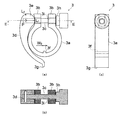
図5(a)〜(c)に示すように、クランプ装置3は、欠環部3a,一対の対向部3b,連結棒3c,レバー部3d及びカム部3eを備えて構成される。欠環部3aは、環の一部を切断されてなる断面C字型に形成され、第一筒部1と第二筒部2との嵌合部位に外嵌される部位である。また、欠環部3aには内側へ向かって突出する凸部3fが形成される。上面視における凸部3fの幅は、図5(a)に示すようにW2(W2<W1)である。凸部3fは第二筒部2の縦スリット2eの内側に配設される。なお、凸部3fはクランプ装置3の位置決めに用いられる部位である。
As shown in FIGS. 5 (a) to 5 (c), the
一対の対向部3bは、欠環部3aの両端から延設され、互いに離隔して対向配置された部位である。これらの対向部3bのそれぞれには、連結棒3cを遊挿する貫通穴3iが穿孔される。連結棒3cは、一対の対向部3b間に跨って掛け渡された部材である。図5(b)に示すように、連結棒3cは二つの貫通穴3iを貫通するように配置される。また、連結棒3cの一端には貫通穴3iよりも大径の係止部3hが形成され、連結棒3cの一端を一方の対向部3bに係止する。連結棒3cの他端には、レバー部3dの基端部が回動自在に支持される。
The pair of facing
レバー部3dの基端部にはカム部3eが形成される。図5(a)に示すように、カム部3eは他方の対向部3bに接触しうる部位である。カム部3eの形状は、レバー部3dの連結棒3cに対する回転中心Pからカム部3eにおける他方の対向部3bとの接触位置までの距離が、レバー部3dの回動角度に応じて変化するように形成される。例えば、図5(a)に示す状態では、回転中心Pから対向部3bとの接触位置までの距離がL1である。一方、レバー部3dを時計回りに90度回転させると、同距離がL2(L2<L1)となる。このように、カム部3eは一対の対向部3b間の距離を縮めて欠環部3aを縮径させるように機能する。
A
キャブ10に固定された第一筒部1とモニタ装置6に固定された第二筒部2とを嵌合させたままクランプ装置3の固定を解除した状態を図6に示す。レバー部3dは、このような固定解除状態でモニタ装置6の側端部6cから先端3gが突出する長さに形成される。また、レバー部3dの先端3gにはオペレータが視認しやすい形状(例えば、丸形や星形といった幾何学的な形状等)に形成され、あるいは目立つように(例えば、赤や黄色,黄色と黒のストライプ等に)着色される。
FIG. 6 shows a state in which the fixing of the
[2.作用,効果]
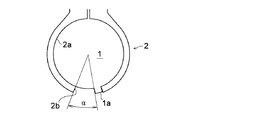
本モニタ固定構造によれば、第一筒部1及び第二筒部2を嵌合させることにより、キャブ10に対するモニタ装置6の筒軸回りの角度を容易に調整することができる。また、スリット孔2dの延設長さに応じて角度の調整範囲を設定することができる。
すなわち、図7に示すように、スリット孔2dが形成された幅から突起部1aの幅を減じた長さの範囲内で突起部1aが移動可能であり、モニタ装置6の配向を角度αの範囲内で自在に調整することができる。また、スリット孔2dを第二筒部2の周方向に長く形成するほど、モニタ装置6の角度の調整範囲がさらに広くなる。
[2. Action, effect]
According to this monitor fixing structure, the angle around the cylinder axis of the
That is, as shown in FIG. 7, the
また、基端部にカム部3eが形成されたレバー部3dを傾動させるという簡単な操作によりクランプ装置3の締め付け及びその解除操作をワンタッチで行うことができる。すなわち、ボルトやナット等の締結具を用いた締結作業が不要であり、モニタ装置6の角度調整の操作性を向上させることができる。なお、クランプ装置3の欠環部3aには第二筒部2の縦スリット2eに係合する凸部3fが形成されるため、第二筒部2に対するクランプ装置3の位置決めが容易であり、この点でも操作性は良好である。
Further, the
さらに、クランプ装置3の締め付けを解除した状態では、図6に示すように、レバー部3dの先端3gがモニタ装置6の側端部6cから飛び出すため、クランプ装置3の締め付け忘れを確実に防止することができる。また、意図せずクランプ装置3の締め付けが緩んだような場合であっても、これを目視で確認することが容易である。また、視認性の高い形状又は色彩でレバー部3dの先端3gが形成されるため、上記の効果を一層高めることができる。
Further, when the
また、縦スリット2eの幅寸法W1が対向面8の間隙2cの幅寸法W0よりも大きく設定されるため、スリット孔2dよりも上端部側における第二筒部2の変形の自由度を高めることができ、クランプ装置3による締結を確実なものとすることができる。なお、図4(b)に示すように、第一筒部1と第二筒部2との嵌合方向がケーブル6bの内挿方向にほぼ直交しているため、ケーブル6bを介してその延長方向に作用する外力があったとしても、その外力が第一筒部1及び第二筒部2を引き抜く方向へ作用しにくく、モニタ装置6の固定状態を保持しやすいという利点もある。
このように、簡素な構成で角度調整を容易かつ確実に行うことができる作業機械のモニタ固定構造を提供することができる。
Further, since the width dimension W 1 of the
As described above, it is possible to provide a monitor fixing structure for a work machine that can easily and reliably adjust the angle with a simple configuration.
[3.その他]
以上、本発明の実施形態について説明したが、本発明は上述の実施形態に限定されるものではなく、本発明の趣旨を逸脱しない範囲で種々変形して実施することができる。
上述の実施形態では、第一筒部1が円筒状に形成されるとともに、第二筒部2に形成された嵌合部2aが第一筒部1と嵌合する中空円筒状に形成されているが、第一筒部1及び第二筒部2の嵌合状態が逆の場合も考えられる。すなわち、第一筒部1及び第二筒部2を有する部材は互いに置換可能である。
[3. Others]
Although the embodiments of the present invention have been described above, the present invention is not limited to the above-described embodiments, and various modifications can be made without departing from the spirit of the present invention.
In the above-described embodiment, the first
また、図2では第一筒部1が下方に位置する第二筒部2に対して上方から内挿されているが、これらの部材の配置上の上下関係を逆にしてもよい。この場合、クランプ装置3の締め付けを解除したときに、モニタ装置6を落下しにくくすることができる。なお、本実施形態の場合であっても、第一筒部1の突起部1aがスリット孔2dの孔壁に係止されるため、モニタ装置6が直ちに落下することはない。
Moreover, although the
また、上述の実施形態では、本モニタ固定構造を油圧ショベルのキャブ10に適用したものを例示したが、ホイールローダやブルドーザ,クレーン車両といった作業機械全般のキャブの内部にモニタ装置を固定するためのモニタ固定構造としての適用が可能である。
In the above-described embodiment, the monitor fixing structure is applied to the
1 第一筒部
1a 突起部
2 第二筒部
2a 嵌合部
2b 内筒面
2c 間隙
2d スリット孔
2e 縦スリット
3 クランプ装置
3a 欠環部
3b 対向部
3c 連結棒
3d レバー部
3e カム部
3f 凸部
3g 先端
3h 係止部
3i 貫通穴
4 第一固定具
4a 第一固定部
4b 第一延出部
5 第二固定具
5a 右ブラケット
5b 左ブラケット
5c 第二固定部
5d 膨出部
5e 貫通穴
6 モニタ装置
6a 裏面
6b ケーブル
6c 側端部
7 シート
8 対向面
10 キャブ
DESCRIPTION OF
Claims (3)
該キャブに固定され、円筒状に形成された第一筒部と、
該モニタ装置に固定され、該第一筒部に嵌合する円筒状に形成された第二筒部と、
該第一筒部と該第二筒部との嵌合部位に外嵌され、該嵌合部位を外側から締め付けて固定するクランプ装置と、
該第一筒部及び該第二筒部の何れか一方に穿孔され、周方向に延設されたスリット孔と、
該第一筒部及び該第二筒部の何れか他方において上記何れか一方へ向けて突設され、該第一筒部及び該第二筒部の嵌合時に該スリット孔の内側に配設される突起部と
を備えたことを特徴とする、作業機械のモニタ固定構造。 A monitor fixing structure for fixing a monitor device inside a cab of a work machine,
A first cylindrical portion fixed to the cab and formed in a cylindrical shape;
A second cylindrical portion fixed to the monitor device and formed in a cylindrical shape to be fitted into the first cylindrical portion;
A clamp device that is externally fitted to a fitting portion between the first tube portion and the second tube portion, and clamps and fixes the fitting portion from the outside;
A slit hole drilled in one of the first cylinder part and the second cylinder part and extending in the circumferential direction;
Either one of the first cylinder part and the second cylinder part protrudes toward one of the above, and is disposed inside the slit hole when the first cylinder part and the second cylinder part are fitted. A monitor fixing structure for a work machine, comprising:
環の一部を切断されてなる断面C字型に形成され、該嵌合部位に外嵌された欠環部と、
該欠環部の両端から延設され、互いに離隔して対向配置された一対の対向部と、
該一対の対向部間に跨って架け渡され、該一対の対向部の一方に係止された連結棒と、
該連結棒に対して回動自在に支持されたレバー部と、
該レバー部の基端において該レバー部と一体形成され、該一対の対向部の他方を該一方へ向けて押圧するとともに、該一対の対向部の他方との接触位置と該レバー部の回動中心との距離を該レバー部の回動角度に応じて変化させるカム部とを有する
ことを特徴とする、請求項1記載の作業機械のモニタ固定構造。 The clamping device is
A missing ring part formed in a C-shaped cross-section formed by cutting a part of the ring and externally fitted to the fitting part;
A pair of opposing portions that are extended from both ends of the missing ring portion and are opposed to each other,
A connecting rod that spans between the pair of opposing portions and is locked to one of the pair of opposing portions;
A lever portion rotatably supported with respect to the connecting rod;
The lever portion is integrally formed with the lever portion at the base end, presses the other of the pair of facing portions toward the one side, and contacts with the other of the pair of facing portions and the rotation of the lever portion. The monitor fixing structure for a work machine according to claim 1, further comprising a cam portion that changes a distance from the center according to a rotation angle of the lever portion.
該レバー部が、該クランプ装置による該嵌合部位の固定時に、該モニタ装置の裏側に収容されて該座席側からの視認範囲外に配置され、かつ、該クランプ装置による該嵌合部位の固定の解除時に、該モニタ装置の裏側からはみ出して該座席側からの視認範囲内に配置される
ことを特徴とする、請求項2記載の作業機械のモニタ固定構造。 The second cylinder portion is fixed to the back side of the monitor device with respect to a seat disposed inside the cab;
When the fitting portion is fixed by the clamp device, the lever portion is accommodated on the back side of the monitor device and is disposed outside the visible range from the seat side, and the fixing portion is fixed by the clamp device. 3. The monitor fixing structure for a work machine according to claim 2, wherein the monitor fixing structure protrudes from the back side of the monitor device and is disposed within a viewable range from the seat side when releasing.
Priority Applications (1)
| Application Number | Priority Date | Filing Date | Title |
|---|---|---|---|
| JP2009260867A JP5222829B2 (en) | 2009-11-16 | 2009-11-16 | Work machine monitor fixing structure |
Applications Claiming Priority (1)
| Application Number | Priority Date | Filing Date | Title |
|---|---|---|---|
| JP2009260867A JP5222829B2 (en) | 2009-11-16 | 2009-11-16 | Work machine monitor fixing structure |
Publications (2)
| Publication Number | Publication Date |
|---|---|
| JP2011105089A JP2011105089A (en) | 2011-06-02 |
| JP5222829B2 true JP5222829B2 (en) | 2013-06-26 |
Family
ID=44229108
Family Applications (1)
| Application Number | Title | Priority Date | Filing Date |
|---|---|---|---|
| JP2009260867A Active JP5222829B2 (en) | 2009-11-16 | 2009-11-16 | Work machine monitor fixing structure |
Country Status (1)
| Country | Link |
|---|---|
| JP (1) | JP5222829B2 (en) |
Families Citing this family (4)
| Publication number | Priority date | Publication date | Assignee | Title |
|---|---|---|---|---|
| JP7003107B2 (en) * | 2017-03-02 | 2022-01-20 | 住友建機株式会社 | Excavator |
| WO2019003412A1 (en) * | 2017-06-30 | 2019-01-03 | 株式会社小松製作所 | Work vehicle |
| JP7054307B2 (en) * | 2018-09-14 | 2022-04-13 | 株式会社竹内製作所 | Work vehicle accoudoir device |
| JP2020076270A (en) * | 2018-11-08 | 2020-05-21 | 日立建機株式会社 | Hydraulic shovel |
Family Cites Families (3)
| Publication number | Priority date | Publication date | Assignee | Title |
|---|---|---|---|---|
| FR2465111A1 (en) * | 1979-09-06 | 1981-03-20 | Itw De France | SELF-LOCKING CLAMP |
| JPH0244108U (en) * | 1988-09-21 | 1990-03-27 | ||
| JP2606244Y2 (en) * | 1993-03-09 | 2000-10-10 | 株式会社シマノ | Bicycle front gear |
-
2009
- 2009-11-16 JP JP2009260867A patent/JP5222829B2/en active Active
Also Published As
| Publication number | Publication date |
|---|---|
| JP2011105089A (en) | 2011-06-02 |
Similar Documents
| Publication | Publication Date | Title |
|---|---|---|
| JP5222829B2 (en) | Work machine monitor fixing structure | |
| CN105026243B (en) | Telescopic steering apparatus and column jacket | |
| JP6065940B2 (en) | Outer column and steering column device | |
| US11148703B2 (en) | Support bracket for steering apparatus and steering apparatus | |
| JP6583440B2 (en) | Steering device | |
| WO2013015339A1 (en) | Steering column support structure | |
| JP5962777B2 (en) | Tilt-type steering device | |
| EP2607207A2 (en) | Steering device | |
| JP5886805B2 (en) | Steering device | |
| JPWO2020100931A1 (en) | Outer column and steering device | |
| JP2018075960A (en) | Back frame for vehicle seat | |
| JP2015194236A (en) | clamp structure | |
| JP5293380B2 (en) | Tilt-type steering device | |
| JPWO2020116350A1 (en) | Steering device | |
| JPH07257322A (en) | Steering lock device | |
| JP4028871B2 (en) | Load cell | |
| JP2010125563A (en) | Axial force-detecting fastening tool | |
| JP2010090570A (en) | Pile head joining structure | |
| JP2019182358A (en) | Steering column device | |
| WO2013057890A1 (en) | Tube clamp device and construction machinery | |
| JP2019214293A (en) | Anchor plate and rotation prevention structure of anchor plate | |
| JP2017154558A (en) | Steering device | |
| JP4842303B2 (en) | Airbag device | |
| JP2013184493A (en) | Grip device for vehicle seat | |
| JP4651349B2 (en) | Vehicle pedal cover |
Legal Events
| Date | Code | Title | Description |
|---|---|---|---|
| A621 | Written request for application examination |
Free format text: JAPANESE INTERMEDIATE CODE: A621 Effective date: 20111221 |
|
| TRDD | Decision of grant or rejection written | ||
| A01 | Written decision to grant a patent or to grant a registration (utility model) |
Free format text: JAPANESE INTERMEDIATE CODE: A01 Effective date: 20130226 |
|
| A977 | Report on retrieval |
Free format text: JAPANESE INTERMEDIATE CODE: A971007 Effective date: 20130228 |
|
| A61 | First payment of annual fees (during grant procedure) |
Free format text: JAPANESE INTERMEDIATE CODE: A61 Effective date: 20130311 |
|
| FPAY | Renewal fee payment (event date is renewal date of database) |
Free format text: PAYMENT UNTIL: 20160315 Year of fee payment: 3 |
|
| R150 | Certificate of patent or registration of utility model |
Ref document number: 5222829 Country of ref document: JP Free format text: JAPANESE INTERMEDIATE CODE: R150 Free format text: JAPANESE INTERMEDIATE CODE: R150 |
|
| R250 | Receipt of annual fees |
Free format text: JAPANESE INTERMEDIATE CODE: R250 |
|
| R250 | Receipt of annual fees |
Free format text: JAPANESE INTERMEDIATE CODE: R250 |
|
| R250 | Receipt of annual fees |
Free format text: JAPANESE INTERMEDIATE CODE: R250 |
|
| R250 | Receipt of annual fees |
Free format text: JAPANESE INTERMEDIATE CODE: R250 |
|
| R250 | Receipt of annual fees |
Free format text: JAPANESE INTERMEDIATE CODE: R250 |
|
| R250 | Receipt of annual fees |
Free format text: JAPANESE INTERMEDIATE CODE: R250 |
|
| R250 | Receipt of annual fees |
Free format text: JAPANESE INTERMEDIATE CODE: R250 |
|
| R250 | Receipt of annual fees |
Free format text: JAPANESE INTERMEDIATE CODE: R250 |
|
| R250 | Receipt of annual fees |
Free format text: JAPANESE INTERMEDIATE CODE: R250 |
|
| R250 | Receipt of annual fees |
Free format text: JAPANESE INTERMEDIATE CODE: R250 |