JP5219868B2 - Layout device, layout method, and layout program - Google Patents
Layout device, layout method, and layout program Download PDFInfo
- Publication number
- JP5219868B2 JP5219868B2 JP2009024148A JP2009024148A JP5219868B2 JP 5219868 B2 JP5219868 B2 JP 5219868B2 JP 2009024148 A JP2009024148 A JP 2009024148A JP 2009024148 A JP2009024148 A JP 2009024148A JP 5219868 B2 JP5219868 B2 JP 5219868B2
- Authority
- JP
- Japan
- Prior art keywords
- layout
- cut
- container
- processing unit
- paper
- Prior art date
- Legal status (The legal status is an assumption and is not a legal conclusion. Google has not performed a legal analysis and makes no representation as to the accuracy of the status listed.)
- Expired - Fee Related
Links
Images


Classifications
-
- G—PHYSICS
- G06—COMPUTING; CALCULATING OR COUNTING
- G06F—ELECTRIC DIGITAL DATA PROCESSING
- G06F3/00—Input arrangements for transferring data to be processed into a form capable of being handled by the computer; Output arrangements for transferring data from processing unit to output unit, e.g. interface arrangements
- G06F3/12—Digital output to print unit, e.g. line printer, chain printer
- G06F3/1201—Dedicated interfaces to print systems
- G06F3/1202—Dedicated interfaces to print systems specifically adapted to achieve a particular effect
- G06F3/1203—Improving or facilitating administration, e.g. print management
- G06F3/1208—Improving or facilitating administration, e.g. print management resulting in improved quality of the output result, e.g. print layout, colours, workflows, print preview
-
- G—PHYSICS
- G06—COMPUTING; CALCULATING OR COUNTING
- G06F—ELECTRIC DIGITAL DATA PROCESSING
- G06F3/00—Input arrangements for transferring data to be processed into a form capable of being handled by the computer; Output arrangements for transferring data from processing unit to output unit, e.g. interface arrangements
- G06F3/12—Digital output to print unit, e.g. line printer, chain printer
- G06F3/1201—Dedicated interfaces to print systems
- G06F3/1223—Dedicated interfaces to print systems specifically adapted to use a particular technique
- G06F3/1237—Print job management
- G06F3/1242—Image or content composition onto a page
- G06F3/1243—Variable data printing, e.g. document forms, templates, labels, coupons, advertisements, logos, watermarks, transactional printing, fixed content versioning
-
- G—PHYSICS
- G06—COMPUTING; CALCULATING OR COUNTING
- G06F—ELECTRIC DIGITAL DATA PROCESSING
- G06F3/00—Input arrangements for transferring data to be processed into a form capable of being handled by the computer; Output arrangements for transferring data from processing unit to output unit, e.g. interface arrangements
- G06F3/12—Digital output to print unit, e.g. line printer, chain printer
- G06F3/1201—Dedicated interfaces to print systems
- G06F3/1223—Dedicated interfaces to print systems specifically adapted to use a particular technique
- G06F3/1237—Print job management
- G06F3/125—Page layout or assigning input pages onto output media, e.g. imposition
- G06F3/1252—Page layout or assigning input pages onto output media, e.g. imposition for sheet based media
-
- G—PHYSICS
- G06—COMPUTING; CALCULATING OR COUNTING
- G06F—ELECTRIC DIGITAL DATA PROCESSING
- G06F40/00—Handling natural language data
- G06F40/10—Text processing
- G06F40/103—Formatting, i.e. changing of presentation of documents
- G06F40/106—Display of layout of documents; Previewing
Description
本発明は、切取り線を含むコンテンツの印刷に際し、当該コンテンツを最適なエリアにレイアウトするレイアウト装置、レイアウト方法、およびレイアウトプログラムに関する。 The present invention relates to a layout device, a layout method, and a layout program for laying out content in an optimum area when printing content including a cut line.
近年、顧客のニーズに合った印刷物を出力するバリアブル印刷が行なわれている。バリアブル印刷の応用として、ダイレクトメールに顧客毎に異なる内容のクーポン(バリアブルクーポン)と、切り取り線とを印刷する技術がある。切り取り線の印刷は、切り取り位置を境に印刷物が切り離されることが特徴であり、このため裏面のレイアウト状態を調節した上で切り取り位置の設定が必要となるが、用紙裏面のレイアウトを考慮したレイアウトは行われていない。このため、切り取り線のある印刷物では、ユーザが試行錯誤しながらレイアウトしなければならず、使い勝手が悪かった。この不都合を解消するためには、ユーザが試行錯誤しながらレイアウト調整を行い、表と裏の切り取り位置を合わせなければならず、使い勝手が悪かった。 In recent years, variable printing for outputting printed matter that meets customer needs has been performed. As an application of variable printing, there is a technique for printing coupons (variable coupons) having different contents for each customer and cut lines on direct mail. Cut line printing is characterized by the fact that the printed material is cut off at the cut position, so it is necessary to set the cut position after adjusting the layout of the back side. Is not done. For this reason, a printed matter with a cut line has to be laid out by the user through trial and error, which is inconvenient. In order to eliminate this inconvenience, the user had to adjust the layout through trial and error and match the cut positions of the front and back, which was inconvenient.
そこで、かかる問題を解決するため、レイアウト枠(コンテナともいう)に流し込むレコードデータをレコードに付加されているキーに基づいて振り分ける技術が提案されている(たとえば、特許文献1を参照。) Therefore, in order to solve such a problem, a technique has been proposed in which record data to be poured into a layout frame (also referred to as a container) is distributed based on a key attached to the record (see, for example, Patent Document 1).
しかしながら、上記特許文献に記載された技術を適用しても、両面印刷では、コンテナに流し込んだデータサイズの差異により表面と裏面の切り取り位置に差異が生じてしまうことがある。また、切り取り線印刷では、コンテンツが分離されることを考慮してレイアウトオーバーフローの対応が必要であるが、上記特許文献に記載された技術ではこの点が考慮されておらず、不備であることは否めない。ただ、レイアウトオーバーフローを行う場合、レイアウト処理により同一面に多くのコンテンツを集中させるために、相対的に文字サイズを小さくしてレイアウトしなければならない。このため、読み難くなるという問題が発生する。 However, even when the technique described in the above-mentioned patent document is applied, in double-sided printing, there may be a difference in the cut position between the front surface and the back surface due to the difference in the data size poured into the container. Further, in the cut line printing, it is necessary to deal with layout overflow in consideration of the separation of contents, but the technique described in the above patent document does not consider this point and is incomplete. can not deny. However, when layout overflow is performed, in order to concentrate a large amount of content on the same surface by layout processing, it is necessary to perform layout with a relatively small character size. For this reason, the problem that it becomes difficult to read occurs.
本発明は、上記従来技術の問題点に鑑み、切取り線を含むコンテンツの印刷に際し、用紙の両面に印刷されるコンテンツの位置を適切に配置し、前記切取り線で用紙が切り離された場合に、当該コンテンツが不自然に分離されるのを防止することを目的とする。 In the present invention, in view of the above-described problems of the prior art, when content including a cut line is printed, the position of the content to be printed on both sides of the paper is appropriately arranged, and when the paper is separated by the cut line, The purpose is to prevent the content from being unnaturally separated.
上述した課題を解決し、目的を達成するため、本発明にかかるレイアウト装置は、レイアウト枠(コンテナ)を配置して用紙両面にレイアウトを行うレイアウト装置であって、前記コンテナと当該コンテナに流し込むコンテンツデータとを関連付ける関連付け処理手段と、前記コンテナの属性に従って切り取り位置を設定する設定手段と、前記関連付け処理手段により関連付けられたコンテンツデータに対応するコンテナのサイズを当該コンテンツデータの容量を参照して算出するレイアウト処理手段と、前記設定手段により設定された切り取り位置を用紙の表裏面で一致させ、当該切り取り位置に重ならないように前記レイアウト処理手段で算出されたコンテナのサイズを補正する切り取り処理手段と、を備えていることを特徴とする。 In order to solve the above-described problems and achieve the object, a layout apparatus according to the present invention is a layout apparatus that arranges a layout frame (container) and performs layout on both sides of a sheet of paper, and the content that flows into the container and the container An association processing means for associating data, a setting means for setting a cutting position according to the attribute of the container, and a size of the container corresponding to the content data associated by the association processing means is calculated with reference to the capacity of the content data Layout processing means for performing matching between the front and back surfaces of the paper and the cutout processing means for correcting the size of the container calculated by the layout processing means so as not to overlap the cutout position. It is characterized by providing.
本発明によれば、切り取り線を含むコンテンツの印刷に際し、用紙の両面に印刷されるコンテンツの位置を適切に配置することで、前記切り取り線に沿って用紙が切り離された場合に、当該コンテンツが不自然に分離されることを防止できる。 According to the present invention, when content including a cut line is printed, by appropriately arranging the position of the content to be printed on both sides of the paper, when the paper is cut along the cut line, the content is It can prevent unnatural separation.
本発明を説明する前提として、まず、本発明のレイアウト装置の基本的な処理内容を説明する。 As a premise for explaining the present invention, first, basic processing contents of the layout apparatus of the present invention will be described.
<レイアウト装置のハードウェア構成>
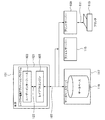
図1は、本発明にかかるレイアウト装置のハードウェア構成を示すブロック図である。図1に示すように、本発明のレイアウト装置を構成する本体101は、入出力インターフェース143を介してキーボード132や、マウス133のようなポインティングデバイス等の入力装置を接続している。また、出力装置としてのビデオディスプレイ144を、ビデオインターフェース137を介して接続している。さらに、プリンタ145を含む出力装置を、入出力インターフェース138を介して接続することも可能である。入出力インターフェース138は、本体101をネットワーク107へ接続することもできる。これにより、ネットワーク107を介して本体101を他のコンピュータ装置に接続することができる。ネットワーク107の典型例としては、ローカルエリアネットワーク(LAN)や、ワイドエリアネットワーク(WAN)などがある。
<Hardware configuration of layout device>
FIG. 1 is a block diagram showing a hardware configuration of a layout apparatus according to the present invention. As shown in FIG. 1, the
また、本体101は、本体101全体の制御を司る少なくとも1つのプロセッサーユニット(CPU)135、たとえば半導体のランダムアクセスメモリ(RAM)やリードオンリーメモリ(ROM)から構成されるメモリユニット136を含んでいる。記憶装置139は、プログラム等を格納するコンピュータ可読媒体との間でデータのやり取りが可能なハードディスクドライブ140やフロッピー(登録商標)ディスクドライブ141を含んでいる。図示していないが、磁気テープドライブなどもまた使用される可能性がある。CD−ROMドライブ142は、不揮発性のデータソースとして提供される。
The
本体101は、LINUX(登録商標)やマイクロソフトウィンドウズ(登録商標)のようなオペレーティングシステムに従い、相互接続バス134を介して通信を行うコンポーネントを利用する。すなわち、各コンポーネントは、相互接続バス134を介して通信可能に接続されており、本体101にインストールされているオペレーティングシステムにより利用される。
The
本発明のレイアウト方法を実現するソフトウェアは、たとえば上記に記述されるような記憶装置139を含むコンピュータの可読媒体に格納される。ソフトウェアは、コンピュータの可読媒体から本体101へロードされ、本体101のCPU135によって実行される。よって、本発明において、後述するフローチャートは、CPU135がソフトウェアを読み出して実行することで実現される。
Software that implements the layout method of the present invention is stored in a computer readable medium including a
<印刷システムの構成>
図2は、本発明にかかるレイアウト装置を含む印刷システムの構成を示す概略図である。図2に示す印刷システムでは、後述するレイアウト編集アプリケーションプログラム121を図1に示したプロセッサ135が実行することで各種の印刷処理が行われる。
<Configuration of printing system>
FIG. 2 is a schematic diagram showing a configuration of a printing system including the layout apparatus according to the present invention. In the printing system shown in FIG. 2, various printing processes are performed by the
レイアウト編集アプリケーションプログラム(レイアウトプログラム)121は典型的にハードディスクドライブ140に常駐し、プロセッサ135により実行される。レイアウト編集アプリケーションプログラム121がCD−ROMやフロッピー(登録商標)ディスク上でエンコードされ、対応するCD−ROMドライブ142やフロッピー(登録商標)ディスクドライブ141を通じて読み込まれユーザに提供される。または、レイアウト編集アプリケーションプログラム121は、ネットワーク接続107から読み込まれるようにしてもよい。
The layout editing application program (layout program) 121 typically resides in the
レイアウト編集アプリケーションプログラム121は、バリアブルデータ印刷(VDP)を行うよう指示し、2つのソフトウェアコンポーネントを含んでいる。1つはレイアウトエンジン105であり、これは長方形の範囲内で与えられた制限やサイズによって矩形と線の位置を計算するためのソフトウェアコンポーネントである。他の1つはユーザインターフェース103であり、これはユーザにドキュメントテンプレートを作成させ、当該ドキュメントテンプレート内でデータソースと関連付けるメカニズムを提供する。
The layout
ユーザインターフェース103とレイアウトエンジン105は、コミュニケーションチャネル123を介して通信する。ドキュメント生成のためのデータソースは、一般的にデータベースアプリケーションを動かしている他のコンピュータによって構成されたデータベースサーバー117上にある典型的なデータベース119である。本体101は、ネットワーク接続107の手段によってデータベースサーバー117と通信する。
The
レイアウト編集アプリケーションプログラム121は、本体101か一般的に他のコンピュータで構成されるファイルサーバー115に保存されるドキュメントテンプレートを生成する。また、データとマージされたドキュメントテンプレートによって構成されたドキュメントを生成する。これらのドキュメントは、本体101のローカルファイルシステムやファイルサーバー115に保存される。または、プリンタ113で直接印刷出力される。
The layout
プリントサーバー109は、直接ネットワークにつながっていないプリンタにネットワーク機能を提供するコンピュータである。プリントサーバー109とプリンタ113は典型的な通信チャネル111を介して接続される。
The
<表示画面>
次に、本発明のレイアウト装置におけるレイアウト処理中にビデオディスプレイ144に表示される画面の一例を示す。図3および図4は、レイアウト処理中に表示される画面の一例を示す図である。
<Display screen>
Next, an example of a screen displayed on the
図3に示すアプリケーションウインドウ301は、操作時にビデオディスプレイ144に表示される。ユーザインターフェース103は、アプリケーションウインドウ301によって形成されたユーザインターフェースを含んでいる。アプリケーションウインドウ301は、画面上の色々な場所に移動することが可能なメニューバー302とツールバー303を有している。また、マウス133の位置・動作によって場所を移動可能なワークエリア306、オプションのルーラー308、パレット311、カーソル/ポインタデバイス313を有している。なお、アプリケーションウインドウ301は、非表示にすることが可能である。
The
メニューバー302は、メニューオプションの階層の下に拡張される多くのメニューアイテム304を有している。ツールバー303は、アプリケーションの特別なモードによって非表示にする、または表示することが可能な多くのツールボタンとウィジット305を有している。オプションのルーラー308は、ワークエリア内のポインター、ページ、ライン、マージンガイド、レイアウト枠(例えば、コンテナともいう)またはオブジェクトの位置を示すために使われる。パレット311は、バリアブルデータライブラリのような追加機能にアクセスするために使われる。また、パレット311は移動、リサイズ、クローズをするためのウインドウコントロール312を有する。なお、レイアウト枠(例えば、コンテナ)とは、コンテンツが流し込まれる部分領域をいう。
ワークエリア306は、ドキュメントテンプレートのデザインを表示・編集するために使われる。これはユーザに下準備で印刷されたドキュメントの概観を把握させること、そしてマージされたドキュメントがバリアブルデータの量・サイズに基づいてどのように変化するかを理解させることを可能にする。もし、外部データソースがテンプレートにリンクされていたら、現在のドキュメントのプレビューができるように、バリアブルテキストとイメージがそれらのコンテナに表示される。
A
また、ワークエリア306は、スクロールバー307と、オプションのルーラー308と、ドキュメントテンプレート309を有する。ドキュメントテンプレート309は、ページが複数あることを示すことができる。与えられたドキュメントテンプレートのページサイズは、ユーザによって指定される。それぞれのドキュメントでの実際のページ数は、バリアブルデータによって変化する。たとえば、1ページ内にフィットできなかったとき、追加のページは自動的に作成される。それぞれのページ内の境界線は、ページ上の印刷可能なオブジェクトの最大幅を示す、任意のページマージン310である。
The
また、図4に示すように、ツールバーエリア303は、ユーザが選択可能な『ボタン』を有する。選択ツールボタン403は、コンテナの辺を選択、移動、サイズ変更、リサイズ、そしてロックまたはロック解除するために使われる。また、所定の操作を行なうことで複数のコンテナが選択される。イメージコンテナツールボタン404は、スタティックあるいはバリアブルイメージが割り当てられるコンテナを作成するために使われる。テキストコンテナツールボタン405は、スタティックあるいはバリアブルテキストが割り当てられるコンテナを作成するために使われる。リンクツールボタン406は、コンテナ間の距離をコントロールするために使われる。なお、これらのボタンは、操作状況に合わせて変化するアイコンのツールチップとして実装される。
As shown in FIG. 4, the
また、図4に示すように、各オブジェクトは、1ページのドキュメントテンプレート309上に表示することも可能である。各オブジェクトは、多数のコンテナ407,408と、任意に適用するアンカーアイコン409と、固定されていない辺410と、リンク412と、スライダー413を有する。
Further, as shown in FIG. 4, each object can be displayed on a
コンテナは、ドキュメントテンプレート内の固定あるいは可変テキスト・イメージを持つスペースであり、他のコンテナやオブジェクトとともにレイアウトされる。コンテナは、マウス133の動作でポインティングデバイス313を使って、ユーザインターフェースで示されるように移動、サイズ調整そして再作成される。より正確には、コンテナは、設定の集まり、視覚的表現そしてインタラクションと編集動作をもっている。コンテナは、以下の(1)〜(4)に示すような性質を有する。
A container is a space having a fixed or variable text image in a document template, and is laid out together with other containers and objects. The container is moved, resized and recreated as shown in the user interface using the
(1)コンテナは、固定あるいは可変のコンテンツが割り当てられる。 (1) Fixed or variable contents are assigned to containers.
(2)コンテナは、コンテンツに適用される背景色、ボーダー、フォント・スタイルのようなテキスト設定のような装飾機能を有する。 (2) The container has a decoration function such as a text setting such as a background color, a border, and a font style applied to the content.
(3)コンテナは、データソースからのデータとマージされる。コンテナ内でのコンテンツの表現は、たとえば印刷されるか、スクリーン144上で表示されるか、その両方が可能である。
(3) The container is merged with data from the data source. The representation of the content in the container can be printed, displayed on the
(4)コンテナは、ユーザインターフェースを有する。ユーザインターフェース103は、背景色やフォントのようなコンテナの装飾機能などを表示する。そして、コンテナの設定の編集や表示を許すための機能を追加する。ユーザインターフェース機能の特別な例としては、ボーダー、もしくはコンテナのサイズや位置を対話的に変更、表示するための角アイコンがある。
(4) The container has a user interface. The
なお、コンテナには制約が設定されている。制約の例としては、「このコンテナのコンテンツの高さは、最大値4インチである。」がある。もうひとつの制約は、「コンテナのコンテンツの左エッジは、それぞれのドキュメントで同じ水平位置で表示しなければならない。」である。本発明で記述される内容は、GUIを使ってこのような制約を表示、編集するためのいろいろな手法である。 A constraint is set on the container. An example of the constraint is “the height of the content of this container is a maximum value of 4 inches”. Another constraint is "The left edge of the container contents must be displayed in the same horizontal position in each document." The contents described in the present invention are various methods for displaying and editing such constraints using a GUI.
固定コンテンツの配置を指定するコンテンツプレイスホルダーは、デジタル印刷技術ではよく知られている。下記の検討で、コンテナは、位置とサイズを持ち、それらは公知の技術で知られている手法で編集され、表示されると想定される。これに対し、本発明では、バリアブルデータ印刷に特化した手法での表示・編集に焦点を合わせる。 Content placeholders that specify the placement of fixed content are well known in digital printing technology. In the discussion below, it is assumed that containers have positions and sizes that are edited and displayed in a manner known in the art. On the other hand, the present invention focuses on display / editing using a technique specialized for variable data printing.
コンテナは、ユーザにドキュメントのコンテンツのサイズ・位置を指定することを可能にする。いくつかのドキュメントは1つのドキュメントテンプレートから生成されるので、コンテナは多数の可能性と制約を指定・表示するために、ユーザインターフェースを使わなければならない。1つのコンテナの辺は、関連付けられたコンテンツがドキュメント内で表示される仮想の境界線を定義する。本発明において、コンテナの左辺を論じることは、関連付けられたコンテンツがどんなドキュメント内でも表示可能な最も左の辺を論じることと同じである。同様に、コンテナの高さを論じることは、生成されたドキュメントで関連付けられたコンテンツの高さの制約を論じるになる。本発明では、ユーザインターフェース103を参照してコンテナの辺あるいは大きさを論じることで、当該区別は明らかになる。
The container allows the user to specify the size and position of the content of the document. Since several documents are generated from a single document template, the container must use a user interface to specify and display a number of possibilities and constraints. An edge of one container defines a virtual border where the associated content is displayed in the document. In the present invention, discussing the left side of a container is the same as discussing the leftmost side whose associated content can be displayed in any document. Similarly, discussing the height of a container will discuss content height constraints associated with the generated document. In the present invention, the distinction is made clear by discussing the side or size of the container with reference to the
以下では、コンテンツの表示を制限するために使われるいくつかの値を定義する用語である「固定」について、場面ごとに説明する。 In the following, “fixed”, which is a term that defines some values used to limit the display of content, will be described for each scene.
(ア)もし,コンテナの幅が固定なら、関連付けられたコンテンツに割り当てられる幅は、全てのドキュメントで同じになるだろう。
(イ)もし、コンテナの高さが固定なら、関連付けられたコンテンツに割り当てられる高さは、全てのドキュメントで同じになるだろう。
(ウ)もし、距離の制約が固定なら、指定された距離は全てのドキュメントのための制約である。
(エ)もし、コンテナの左右辺が固定なら、辺の水平位置がページに関して全てのドキュメントで同じであることを意味する。しかし、コンテナの高さもしくは垂直方向の位置は、変わるかもしれない。
(オ)もし、コンテナの上下辺が固定なら、辺の垂直位置がページに関して全てのドキュメントで同じであることを意味する。しかし、コンテナの幅あるいは水平位置は変わることがある。
(カ)コンテナの垂直軸はコンテナの右と左辺の平行で、そして中間に位置される想像上の垂直線である。もし、コンテナの垂直軸が固定なら、コンテナの左右辺の水平位置の平均は、すべてのドキュメントで同じである。この制約で、コンテナの幅は変化するかもしれない。また、左右辺両方が異なったドキュメントで、垂直軸に最も遠いかもしくは最も近いかもしれない。
(A) If the container width is fixed, the width allocated to the associated content will be the same for all documents.
(B) If the container height is fixed, the height assigned to the associated content will be the same for all documents.
(C) If the distance constraint is fixed, the specified distance is a constraint for all documents.
(D) If the left and right sides of the container are fixed, it means that the horizontal position of the side is the same for all documents with respect to the page. However, the height or vertical position of the container may change.
(E) If the upper and lower sides of the container are fixed, it means that the vertical position of the side is the same for all documents with respect to the page. However, the width or horizontal position of the container can change.
(F) The vertical axis of the container is an imaginary vertical line located in the middle between the right and left sides of the container. If the container's vertical axis is fixed, the average horizontal position of the left and right sides of the container is the same for all documents. This constraint may change the width of the container. It may also be the document that is different on both the left and right sides and that is farthest or closest to the vertical axis.
(キ)同様に、もし、水平軸が固定なら、コンテナの上そして下辺が垂直に位置されるように制約される。しかし、高さは、この制約には影響されない。
(ク)もし、水平、垂直軸両方が固定なら、コンテナの中心位置が固定されていることを意味する。しかし、幅、高さはこの制約に影響されない。
(ケ)もし、コンテナの角、コンテナの辺の中間位置、もしくはコンテナの中心位置が固定なら、すべてのドキュメントで同じ場所に、コンテナに関連付けられた形式で表示される。
(G) Similarly, if the horizontal axis is fixed, the top and bottom sides of the container are constrained to be positioned vertically. However, the height is not affected by this constraint.
(H) If both the horizontal and vertical axes are fixed, it means that the center position of the container is fixed. However, the width and height are not affected by this restriction.
(G) If the corner of the container, the middle position of the container side, or the center position of the container is fixed, all documents are displayed in the same location in the form associated with the container.
(コ)垂直辺もしくは軸はページの左辺、または右辺、または左ページマージン、または右ページマージン、または他の水平位置に関連付けされて固定になる。同様に、水平辺もしくは軸はページの上、または下辺、またはマージン、または他の垂直位置に関連付けされて固定になる。 (E) The vertical side or axis is fixed in association with the left side, right side, left page margin, right page margin, or other horizontal position of the page. Similarly, the horizontal side or axis is fixed relative to the top or bottom side of the page, or margin, or other vertical position.
「固定」の反対は、辺、軸、角、中間位置、またはドキュメント制約がドキュメント間で変化するかもしれないことを意味する「可変」である。 The opposite of “fixed” is “variable”, meaning that the side, axis, corner, intermediate position, or document constraint may vary from document to document.
さらに、コンテナは、テキストコンテナとイメージコンテナの2種類で記述される。テキストコンテナは、テキストの他、埋め込みのイメージを有する。また、イメージコンテナは、イメージのみを有する。 Furthermore, two types of containers are described: text containers and image containers. The text container has an embedded image in addition to text. The image container has only an image.
図4に示すように、新規のテキストコンテナは、テキストコンテナツール404をマウス133でクリックし、テンプレート309に四角形をドラッグすることによって、ドキュメントテンプレート309上に作成される。また、新規のイメージコンテナも、イメージコンテナツール405をマウス133でクリックし、テンプレート309に四角形をドラッグすることによって、ドキュメントテンプレート309上に作成される。また、コンテナは、適切なツール(たとえば、テキストコンテナツール404や、イメージコンテナツール405)をアクティブにした後に、ドキュメントテンプレート309上でクリックすることによって単純に作成される。さらに、デフォルトサイズのコンテナを挿入、または新規コンテナの寸法を入れるために、ダイアログボックスまたは他のプロンプトが提供される。いくつかのコンテナは自動的に前もって定義されたか、計算されたスキーマによって、作成・配置される。
As shown in FIG. 4, a new text container is created on the
ところで、コンテナを表示する際、前述した36の辺の状態それぞれが、グラフィカルな表現で描画されるのが好ましい。いくつかの辺の状態は、いくつかの状況で表現を分け合うため、36のグラフィック表示より少なくなることもある。以下に、コンテナの模範的な辺ルールを示す。図5は、典型的なコンテナルールを説明するための図である。 By the way, when displaying a container, it is preferable that each of the 36 side states described above is drawn in a graphical representation. Some edge states may be less than 36 graphic displays because they share representation in some situations. The following are exemplary side rules for containers. FIG. 5 is a diagram for explaining typical container rules.
図5(a)〜図5(d)に示すように、レイアウト編集アプリケーションプログラム121は、辺の状態を表現するために、塗りつぶし線(アイテム503)または点線(アイテム504)で辺を描く。また、アンカー(辺の近くに描画されたアイテム506,507,509によって示されるような線、形状、アイコン)や、ハンドル(移動、修正するために辺や形の近くに描画されたコントロール点(アイテム502))を付加する。さらに、スライダー(辺の両サイドに描画された短い並行線(たとえば、図4のスライダー413))や、拡縮アイコン(アイテム505)や、色を付加する。このようなコンテナ表示に関するルールを以下の(A)〜(H)に示す。
As shown in FIGS. 5A to 5D, the layout
(A)それぞれの辺を固定するために、塗りつぶし線で描画する。
(B)もし幅が固定なら、左と右の辺を塗りつぶし線で描画する。
(C)もし高さが固定なら、上と下の辺を塗りつぶし線で描画する。
(D)軸は描画しない。
(E)まだ描画されていない全ての辺は、それぞれの辺の近くに拡縮アイコンが描画され、点線になる。
(F)垂直辺あるいは軸のそれぞれのペアで、もし両者が固定なら、交差点にアンカーが描画される。
(G)それぞれの固定辺で、もし辺のどこにもアンカーが描画されていなければ、エッジの中央にスライダーが描画される。
(H)垂直辺あるいは軸のそれぞれのペアで、もしアンカーやスライダーが描画されていなければ、交差点にハンドルが描画される。
(A) Draw with solid lines to fix each side.
(B) If the width is fixed, the left and right sides are drawn with solid lines.
(C) If the height is fixed, the upper and lower sides are drawn with solid lines.
(D) An axis is not drawn.
(E) For all sides that have not yet been drawn, an enlargement / reduction icon is drawn near each side and becomes a dotted line.
(F) For each pair of vertical sides or axes, if both are fixed, an anchor is drawn at the intersection.
(G) For each fixed side, if no anchor is drawn anywhere on the side, a slider is drawn at the center of the edge.
(H) If no anchor or slider is drawn for each pair of vertical sides or axes, a handle is drawn at the intersection.
また、可変の辺が描画される場所は、コンテナに割り当てられるコンテンツに依存する。 The place where the variable side is drawn depends on the content assigned to the container.
(a)図4に示した辺410のように、点線はコンテナのコンテンツに依存して、ドキュメント内の辺の位置を意味する。
(A) Like the
(b)塗りつぶし線は制限された辺を意味する。なぜなら、辺は固定されている(図4の辺414参照)か、コンテナの幅、高さが固定されている(図4のコンテナ408は両方が固定されている)からである。
(B) A solid line means a restricted side. This is because the sides are fixed (see
(c)アンカーは、辺そして軸が交差した場所が固定されていることを意味する。図4に示したアイコン409は、交差する辺414が固定されていることを意味するアンカーアイコンの例である。
(C) An anchor means that a place where sides and axes intersect is fixed. The
(d)スライダーは、関係付けられた辺が固定されていることを意味する。しかし、コンテナは、辺に沿って多くの位置「スライドの長さ」で位置を定められる。たとえば、図4では、スライダー413は、コンテナ408のコンテンツがドキュメント内で特定のダイアグラムで表される位置において左または右に表示されることがある。
(D) The slider means that the associated side is fixed. However, the container is positioned at many positions “slide length” along the side. For example, in FIG. 4, the
また、幅・高さの最小値・最大値の設定は、副次的なダイアログウインドウに表示される。たとえば、図5(a)において、コンテナ501は、幅・高さ両方が固定されていない。固定された辺503は、塗りつぶし線で表現される。可変の辺504は、点線で表現される。また、拡縮アイコン505は、隣接する辺504が可変であることを示す。
The setting of the minimum value and maximum value of the width and height is displayed in a secondary dialog window. For example, in FIG. 5A, the width and height of the
図5(b)において、コンテナ501は幅・高さ両方が可変である。アンカーアイコン506は、交差している両方の辺503が固定されていることを示している。
In FIG. 5B, the
図5(c)において、コンテナ501は、コンテナの拡大あるいは縮小が任意のアンカーアイコン507で示されるような中心点の周りを平等に広がるという状態で、幅・高さ両方が可変である。
In FIG. 5C, the
図5(d)において、コンテナ501は、上辺508が固定されていることを除けば、幅・高さ両方が可変である。上辺508の中心に位置付けられて示されるアンカーアイコン509は、固定されている。なお、コンテナ501の左・右辺は、アンカーアイコン509を通り垂直に描画される中心軸(垂直軸)の周りを、拡大・縮小することを示す。
In FIG. 5D, the width and height of the
次に、コンテナにリンクを設定する手順について説明する。図6は、コンテナにリンクを設定する手順を示すフローチャートである。なお、以下に示す本願のフローチャートの各処理は、図1に示したプロセッサ135が図2に示したレイアウト編集アプリケーションプログラム121を実行することにより行われる。
Next, a procedure for setting a link in a container will be described. FIG. 6 is a flowchart showing a procedure for setting a link in a container. Each process of the flowchart of the present application shown below is performed when the
図6に示すフローチャートにおいて、レイアウト編集アプリケーション121は、コンテナを作成する(ステップS601)。リンクを設定するためには、リンクを設定するためのコンテナ(最低2つ)を作成する必要がある。図7は、2つのコンテナを作成してリンクを設定する場合の例を示している。各コンテナは、図4に示したようなドキュメントテンプレート309上に作成される。
In the flowchart shown in FIG. 6, the
次に、レイアウト編集アプリケーション121は、リンクツールが選択されたことを認識する(ステップS602)。図7(a)〜図7(c)は、コリンクを設定する動作を順に示している。以下では、図の順にしたがって説明を続ける。
Next, the
図7(a)に示された辺701,702は、固定されている辺を意味する。また、アンカー703,704は、アンカー409と同様のアンカーである。なお、符号705は、マウスポインタを示す。
Sides 701 and 702 shown in FIG. 7A mean fixed sides. The anchors 703 and 704 are the same anchors as the
図6に戻り、レイアウト編集アプリケーション121は、コンテナが選択されたことを認識する(ステップS603)。具体的には、リンクを設定する片方のコンテナをクリックして選択する。
Returning to FIG. 6, the
次に、レイアウト編集アプリケーション121は、リンクを設定する他方のコンテナが選択されたことを認識する(ステップS604)。たとえば、図7(b)に示すように、もう片方のコンテナまでマウスポインタ705を移動して、クリックする。図7(b)に示された線706は、図7(a)においてクリックをした位置と移動したマウスポインタ705とを結んだ線を示しており、どの位置にリンクが設定されるのかをユーザに示すUI(ユーザーインターフェース)である。
Next, the
次に、レイアウト編集アプリケーション121は、リンクUIを表示する(ステップS605)。これは、ステップS604の処理が終了した後、設定した場所に、レイアウト編集アプリケーションプログラム121がリンクUI707を表示する。コンテナは、図7(c)に示した状態になる。
Next, the
最後に、レイアウト編集アプリケーション121は、コンテナのUIを変更する(ステップS606)。すなわち、リンクが設定されたことにより、レイアウト編集アプリケーションプログラム121がコンテナのUIを変更する。図7(c)に示されている辺708は、点線で形成された辺であり、前述したように可変の辺である。つまり、リンクを設定したことによりコンテナ同士が関連して変更する状態に設定されたにも関わらず、コンテナの変更を許可しないという矛盾を防ぐための処理である。また、アイテム709は、図5に示されたアイテム505と同じで、リンクを設定したことにより、コンテナが変化できる方向をユーザに視覚的に示す印である。図7(c)に示した例では、左のコンテナの右辺と右のコンテナの左辺が可変に変化している。ただし、これは一例であり、たとえば、右コンテナが、図4のスライダー413と同様な設定に変化してもかまわない。
Finally, the
次に、レイアウトの計算について説明する。図8は、レイアウト計算における全体の手順を示すフローチャートである。前述のように、本発明のレイアウト装置では、コンテナを作成して、当該コンテナ間に関連付けを行いテンプレートを作成するレイアウトモードを実行する。また、作成したテンプレートのコンテナにレコードに含まれるコンテンツデータを挿入して、レイアウト結果をプレビューするプレビューモードを実行する。このプレビューモードにおいて、実際にレコードのコンテンツデータが挿入され、レイアウトを計算する。ただし、プレビューモードは、表示上でのレイアウト計算である。実際に印刷する場合においても、レコードを挿入してレイアウトを計算する。その際の計算方法も同じである。 Next, layout calculation will be described. FIG. 8 is a flowchart showing an overall procedure in layout calculation. As described above, in the layout apparatus of the present invention, a layout mode is executed in which containers are created and associated with each other to create a template. Also, a preview mode for previewing the layout result is executed by inserting the content data included in the record into the created template container. In this preview mode, the record content data is actually inserted, and the layout is calculated. However, the preview mode is a layout calculation on the display. Even in actual printing, a record is inserted to calculate the layout. The calculation method at that time is the same.
まず、レイアウト編集アプリケーション121は、プレビューモードを選択し(ステップS801)、プレビューするレコードを選択してそのレコードのコンテンツデータをコンテナに挿入する(ステップS802)。続いて、レイアウト編集アプリケーション121は、コンテンツデータをレイアウトするための計算を行い(ステップS803)、計算されたレイアウト結果をプレビューする(ステップS804)。
First, the
さらに、レイアウト編集アプリケーション121は、他のレコードについてもプレビューするか否かを判断する(ステップS805)。ここで、他のレコードについてプレビューを行う必要がない場合(ステップS805:No)は、プレビューモードを終了する(ステップS807)。一方、他のレコードについてプレビューを行う必要がある場合(ステップS805:Yes)は、プレビューを行うべき他のレコードを選択する(ステップS806)。この後、ステップS803へ移行する。
Furthermore, the
なお、プレビューモードでなく印刷時では、印刷するレコードすべてについて順にレイアウトの計算を行う。したがって、ステップS805とステップS807の処理は存在しない。すべてのレコードについて印刷が終了した時点で終了する。 Note that when printing is performed instead of the preview mode, the layout is calculated in order for all records to be printed. Therefore, there is no processing in step S805 and step S807. The process ends when printing is completed for all records.
次に、レイアウト計算処理(図8のステップS803)について詳細に説明する。図9は、詳細なレイアウト計算処理の手順を示すフローチャートである。 Next, the layout calculation process (step S803 in FIG. 8) will be described in detail. FIG. 9 is a flowchart showing a procedure of detailed layout calculation processing.
図9に示すフローチャートにおいて、レイアウト編集アプリケーション121は、レイアウトを計算するコンテナの集合を求める(ステップS901)。
In the flowchart shown in FIG. 9, the
図10は、レイアウト計算時におけるコンテナの集合を説明するための図である。図10に示すように、ページ上に4つのコンテナがレイアウトされており、コンテナAとコンテナB、そしてコンテナCとコンテナDがリンクによって関連付けされている。したがって、コンテナA・Bが集合1、コンテナC・Dが集合2となる。ここでも、図4と同様、アンカー1101、辺1102、コントローラー1103、矢印1104、辺1105、リンク1106、およびスライダー1107などが表示される。なお、辺1102は固定された辺、辺1105は可変の辺を示している。また、矢印1104は、可変の辺の変化方向を示している。
FIG. 10 is a diagram for explaining a set of containers at the time of layout calculation. As shown in FIG. 10, four containers are laid out on the page, and container A and container B, and container C and container D are linked by a link. Accordingly, containers A and B are set 1 and containers C and D are set 2. Here, as in FIG. 4, an
次に、レイアウト編集アプリケーション121は、1つの集合を選択する(ステップS902)。ここでは、ステップS901で求めたコンテナの集合から、レイアウトを計算するために1つを選択する。
Next, the
次に、レイアウト編集アプリケーション121は、レイアウトの最適化を行う(ステップS903)。ここでは、ステップS902で選択されたコンテナの集合について、レイアウトの計算を行う。より具体的には、レイアウトされるコンテナのサイズが、実際のコンテンツのサイズとできる限り差が少なくなるように、レイアウトの最適化を行う。レイアウトの最適化は、動的にサイズを変化することが可能なように関連付けられたコンテナにおいて、それぞれに挿入されるコンテンツのサイズとレイアウトされるサイズとの差が、同じになるように行われる。
Next, the
そして、レイアウト編集アプリケーション121は、ルール違反しているか否かを判定する(ステップS904)。ここでルールとは、レイアウト作成時にユーザによって設定される制限であり、コンテナのサイズと位置、リンクの長さなどである。ステップS904においてルール違反している場合(ステップS904:Yes)は、再度ステップS903の処理を実行する。
Then, the
一方、ステップS904においてルール違反していない場合(ステップS904:No)、レイアウト編集アプリケーション121は、全コンテナの集合について計算が終了したか否かを判定する(ステップS905)。ここで、全コンテナの集合について計算が終了していない場合(ステップS905:No)は、ステップS902へ戻る。一方、全コンテナの集合について計算が終了した場合(ステップS905:Yes)は、処理を終了する。
On the other hand, when the rule is not violated in step S904 (step S904: No), the
次に、レイアウト計算時に表示されるUIの例を示す。図11(a)〜図11(c)は、レイアウト計算時に表示されるUIの一例である。これは、たとえば、図4に示したようなドキュメントテンプレート309上に作成される。
Next, an example of a UI displayed at the time of layout calculation is shown. FIG. 11A to FIG. 11C are examples of UIs displayed during layout calculation. This is created on a
図11(a)は、あるレコードが挿入されレイアウトが決定された状態を示している。図4と同様、アンカー1001,1002、リンク1008などが表示される。なお、辺1003,1004は固定された辺を、辺1005は可変の辺を示している。また、矢印1006、1007は、可変の辺の変化方向を示している。
FIG. 11A shows a state in which a certain record is inserted and the layout is determined. As in FIG. 4, anchors 1001, 1002, a
図11(b)は、図11(a)の状態に新しいコンテンツのサイズを重ねて示している。ここでは、コンテンツ1009で示される大きさのコンテンツがコンテナに挿入される。その後、レイアウト計算が行われる。
FIG. 11B shows the new content size superimposed on the state of FIG. Here, content having a size indicated by
図11(c)は、レイアウト計算された結果を示している。計算後の各コンテナのサイズは、実際挿入されるコンテンツのサイズと同等に差異があるように計算され、かつ前述したルールを違反しないように計算される。図11(c)では、図11(b)で示された挿入されるコンテンツ1009のサイズと計算後のコンテンツ1010のサイズとは、双方において同等な差異がある。
FIG. 11C shows the result of layout calculation. The size of each container after calculation is calculated so that there is a difference equivalent to the size of the content that is actually inserted, and is calculated so as not to violate the rules described above. In FIG. 11C, the size of the
以下、各実施形態を示し、本発明を詳細に説明する。 Hereinafter, each embodiment is shown and this invention is demonstrated in detail.
[第1実形態]
<レイアウト装置の機能的構成>
図12は、第1実施形態にかかるレイアウト装置の機能的構成を示すブロック図である。なお、以下に示す各機能部は、プロセッサ135がレイアウト編集アプリケーションプログラム121を実行することによって実現される。なお、本願は両面印刷が設定された場合に有効である。
[First embodiment]
<Functional configuration of layout device>
FIG. 12 is a block diagram illustrating a functional configuration of the layout apparatus according to the first embodiment. The following functional units are realized by the
モード設定部11は、UIで指定されたコンテナ作成モードを設定する(詳細は後述)。関連付け処理部12は、前記UIで指定されたコンテナに対して流しこむコンテンツデータを関連付ける。設定部13は、処理モードを設定する。たとえば、切り取りモードを設定する場合、前記コンテナの属性に従い切り取り位置を設定する(詳細は後述)。検出部14は、レイアウト計算の実行命令を検出する。レイアウト処理部15は、各コンテナに対して関連付け処理部12で関連付けられたコンテンツデータを参照して当該コンテナのサイズを算出する。判定部16は、設定部13で設定された処理モードが切り取りモードであるか否かを判定する。切り取り処理部17は、設定部13により設定された切り取り位置を用紙の表裏面で一致させ、当該切り取り位置に重ならないようにレイアウト処理部15で算出されたコンテナのサイズを補正する(詳細は後述)。表示処理部18は、レイアウト結果を前記UIに表示する。
The
<レイアウト装置の全体処理>
次に、本実施形態のレイアウト装置の全体処理を説明する。図13は、第1実施形態にかかるレイアウト装置の全体処理手順を示すフローチャートである。なお、以下の処理は、図14に示すレイアウト装置のUIを参照しながら説明する。
<Overall processing of layout device>
Next, the entire process of the layout apparatus according to the present embodiment will be described. FIG. 13 is a flowchart showing an overall processing procedure of the layout apparatus according to the first embodiment. The following processing will be described with reference to the UI of the layout apparatus shown in FIG.
レイアウト編集アプリケーション121は、コンテナ作成モードへ移行する(ステップS1301)。この処理は、たとえば図14のアイコン1203が押下されると、図12のモード設定部11がコンテナ作成モードへ移行させる。そして、ページマージンのエリア1202内において、マウスのドラッグによりコンテナ1207−1210が描画されること。
The
次に、レイアウト編集アプリケーション121は、コンテナとコンテンツデータを関連付ける(ステップS1302)。この処理は、たとえば、図14の「Data1」アイコン1206が押下されると、図12の関連付け処理部12が、指定されたコンテナとコンテンツデータとの関連付けを行う。なお、関連付けは、データの各フィールド情報と各コンテナを指定して関連付けるようにしてもよいし、データファイルを指定しそのデータファイルからシーケンシャルに関連付けるようにしてもよい。また、関連付けしたコンテナの属性として、各コンテナに対して「切り取り属性」、「非切り取り属性」、「属性なし」の印刷後処理に関する設定も行う。「切り取り属性」として設定された部分は、切り取られて使用される前提でレイアウト処理される。なお、「属性なし」は、切り取られても良いコンテナを指す。なお、コンテンツと関連付ける形で各属性を持たせるようにしてもよい。
Next, the
次に、レイアウト編集アプリケーション121は、切り取り位置を設定する(ステップS1303)。たとえば、図14の「切り取りする」アイコン1205を押下することで、レイアウトする際に切り取り処理を実施するか否かの選択として「ミシン目にする」、「ミシン目にしない」の切り取りモードを選択設定する。加えて、たとえば「表面の切り取り位置にあわせる」アイコン1212を押下することで、切り取り処理を行う場合の処理方法を選択登録する。本実施形態では、「表面の切り取り位置に合わせる」、「裏面の切り取り位置に合わせる」、「自動」の3つのモードを選択登録することができる。この設定は、ユーザの指示に従い図12の設定部13が行う。
Next, the
次に、レイアウト編集アプリケーション121の検出部14は、実行ボタンが押下されたか否かを検出する(ステップS1304)。ここで、実行ボタン1211の押下が検出できなかった場合(ステップS1304:No)は、ステップS1301へ戻る。
Next, the
一方、ステップS1304において実行ボタン1211の押下が検出された場合(ステップS1304:Yes)、レイアウト編集アプリケーション121は、レイアウト処理を実行する(ステップS1305)。ステップS1305の処理は、各コンテナにステップS1302で関連付けたコンテンツデータの容量を基に必要なコンテナサイズを算出するものである。ここで、コンテナサイズは、前述のように各コンテナに流し込むコンテンツと各コンテナサイズとの相関関係で決定される。
On the other hand, when pressing of the
次に、レイアウト編集アプリケーション121は、切り取りモードであるか否かを判定する(ステップS1306)。この判定は、図12の判定部16がステップS1303で設定したモードに対して行う。ここで、切り取りモードでない場合(ステップS1306:No)、すなわち「ミシン目にしない」場合であれば、ステップS1308へ移行する。
Next, the
一方、ステップS1306において切り取りモードである場合(ステップS1306:Yes、すなわち「ミシン目にする」が設定された場合)、レイアウト編集アプリケーション121は、切り取り処理を実行する(ステップS1307)。
On the other hand, when the cut mode is selected in step S1306 (step S1306: Yes, that is, when “perforate” is set), the
最後に、レイアウト編集アプリケーション121は、レイアウト結果を表示する(ステップS1308)。
Finally, the
次に、前記切り取り処理(図13のステップS1307)について詳細に説明する。図15は、切り取り処理(図13のステップS1307)の手順を示すフローチャートである。以下の処理は、図12の切り取り処理部17が実行する。
Next, the cutting process (step S1307 in FIG. 13) will be described in detail. FIG. 15 is a flowchart showing the procedure of the cutting process (step S1307 in FIG. 13). The following processing is executed by the
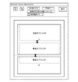
処理部17は、用紙の表裏レイアウトエリアに切り取り位置を設定する(ステップS1401)。この処理は、図13のステップ1302でコンテナに設定された「切り取り属性」、「非切り取り属性」に従って、用紙の表裏レイアウトエリア上の切り取り位置を設定する。この処理を実行すると、非切り取り属性と切り取り属性のコンテナの境界部分中央に切り取り位置が設定される。その処理結果を図16に示す。
The
図16は、切り取りエリアの設定例を示す図である。図16に示すように、表面では、コンテナBとコンテナCとの間で属性の切り替えがあるため、その境界部分に切り取り線(破線で表示)が設定される。同様に、裏面では、コンテナDとコンテナEとの間で属性の切り替えがあるため、その境界部分に切り取り線が設定される。 FIG. 16 is a diagram illustrating an example of setting a cut area. As shown in FIG. 16, on the surface, since there is an attribute switching between the container B and the container C, a cut line (indicated by a broken line) is set at the boundary portion. Similarly, on the back surface, since there is an attribute switching between the container D and the container E, a cut line is set at the boundary portion.
図15に戻り、処理部17は、切り取りエリアに画像があるか否かを判定する(ステップS1402)。ここで、切り取りエリアに画像がない場合(ステップS1402:No)、すなわち表面、裏面どちらかの面に画像が全く存在しない場合は、処理終了となる。この後は、図13のステップS1308の処理を行う。
Returning to FIG. 15, the
一方、ステップS1402において切り取りエリアに画像がある場合(ステップS1402:Yes)、処理部17は、裏面に切り取り位置設定があるか否かを判定する(ステップS1403)。ここで、裏面に切り取り位置設定がない場合(ステップS1403:No)、処理部17は、切り取り位置のレイアウト調整の必要なしと判断し、処理終了となる。この後は、図13のステップS1308の処理を行う。
On the other hand, when there is an image in the cut area in step S1402 (step S1402: Yes), the
一方、ステップS1403において裏面に切り取り位置設定がある場合(ステップS1403:Yes)、処理部17は、表面と裏面の切り取り位置に差異があるか否かを検出する(ステップS1404)。ここで、表面と裏面の切り取り位置に差異がない場合(ステップS1404:No)は、処理終了となる。この後は、図13のステップS1308の処理を行う。
On the other hand, when there is a cut position setting on the back surface in step S1403 (step S1403: Yes), the
一方、ステップS1404において表面と裏面の切り取り位置に差異がある場合(ステップS1404:Yes)、処理部17は、切り取り位置の決定を行う(ステップS1405)。ここでは、図13のステップ1303で登録された切り取りモードに従う。
On the other hand, when there is a difference between the cutting positions on the front surface and the back surface in step S1404 (step S1404: Yes), the
すなわち、ステップ1303において「表面の切り取り位置に合わせる」と登録されている場合、処理部17は、表面の切り取り位置に合うように裏面の切り取り位置を変更する(ステップS1406)。たとえば、図16に示すように、表面の切り取り位置と裏面の切り取り位置が異なる場合、裏面の切り取り位置が表面の切り取り位置と一致するように、裏面の切り取り位置を補正する。
That is, when “match with the front surface cutting position” is registered in step 1303, the
また、ステップ1303において「裏面の切り取り位置に合わせる」と登録されている場合、処理部17は、裏面の切り取り位置に合うように表面の切り取り位置を変更する(ステップS1407)。たとえば、図16に示すように、表面の切り取り位置と裏面の切り取り位置が異なる場合、表面の切り取り位置が裏面の切り取り位置と一致するように、表面の切り取り位置を補正する。
If it is registered in step 1303 that “match with the cut position on the back surface”, the
また、ステップ1303において「自動」と登録されている場合、処理部17は、表面と裏面との切り取り位置の中間を切り取り位置として決定する(ステップS1408)。たとえば、図16に示すように、表面の切り取り位置と裏面の切り取り位置が異なる場合は、表面の切り取り位置と裏面の切り取り位置の中間点を算出する。そして、算出された中間点を新たな切り取り位置となるように、表/裏面の各切り取り位置を補正する。
If “automatic” is registered in step 1303, the
そして、処理部17は、レイアウト処理を行う(ステップS1409)。ここでは、ステップS1406〜ステップS1408の処理で決定された切り取り位置に従ってコンテナサイズを算出し再レイアウトする。以下では、図16、図17を用いてコンテナサイズの算出方法を簡単に説明する。図17は、新たな切り取り線が決定された後の再レイアウトを行う様子を説明するための図である。
Then, the
たとえば、縦方向の用紙サイズをLとし、ステップS1406の処理前の用紙の上端から切り取り位置までの距離をOffsetをAとする。そして用紙の上端からステップS1406の処理後に決定した切り取り位置までの距離を図17のOffsetをBとする。OffsetA,Bの比率から拡縮率 A/Bを算出し、前記拡縮率をコンテナDの縦方向に適用してコンテナサイズを決定する。同様に、コンテナEに対しても切り取り位置を基準に拡縮率(L−OffsetA)/(L−OffsetB)を算出して適用する。ステップS1407およびステップS1408の後の再レイアウト処理も同様である。 For example, assume that the paper size in the vertical direction is L, and the distance from the upper end of the paper before the processing in step S1406 to the cutting position is A. Then, the offset from the upper end of the paper to the cut position determined after the processing of step S1406 is B in Offset in FIG. The enlargement / reduction ratio A / B is calculated from the ratio of Offset A, B, and the container size is determined by applying the enlargement / reduction ratio in the vertical direction of the container D. Similarly, the enlargement / reduction ratio (L-OffsetA) / (L-OffsetB) is calculated and applied to the container E based on the cut position. The same applies to the re-layout process after step S1407 and step S1408.
以上の処理を行うことで、図17に示すように、用紙の表面と裏面とにおいてコンテンツと切り取り位置とが重ならないレイアウト結果を出力することができる。 By performing the above processing, as shown in FIG. 17, it is possible to output a layout result in which the content and the cutting position do not overlap on the front surface and the back surface of the sheet.
ところで、図13のステップ1308の処理として、図14の透過編集モード1213の設定をONにした場合は以下のような処理が実行される。すなわち、ステップ1409のレイアウト処理の拡縮率があらかじめ設定されているしきい値の範囲外の場合、レイアウト編集アプリケーション121は、自動レイアウト上の問題ありと判断する。前記しきい値が範囲外の場合、表示処理部18は、表面コンテナに裏面コンテナを重ね(OR)て表示し、手動でコンテナの編集を可能にする。ここでは、透過しているコンテナは破線等で識別可能な形式で表示する(重ね表示を透過編集表示と呼ぶことにする)。図18は、透過編集表示の一例を示す図である。なお、透過については、裏面コンテナに表面コンテナを重ねあわせて表示するようにしてもよい。
By the way, as the processing of step 1308 in FIG. 13, when the setting of the
本実施形態では、上記各処理を実行することにより、切り取り線印刷のレイアウトに関して、コンテナ属性によって切り取り位置を設定する。そして、表/裏面の切り取り位置が異なる場合には、切り取り位置が一致するように表面と裏面のコンテンツをレイアウトする。このようにすることにより、表裏面の切り取り位置が異なる場合でも、表裏の切り取り位置を一致させ、コンテンツが挿入されるコンテナも切り取り位置にあったサイズになるように再レイアウトすることができる。したがって、前記切取り位置で用紙が切り離された場合でも、コンテンツが不自然に分離されることを防止できる。 In the present embodiment, by performing each of the above processes, the cutting position is set by the container attribute with respect to the layout of the cutting line printing. Then, when the front / back surface cut positions are different, the front and back contents are laid out so that the cut positions match. In this way, even when the front and back cutout positions are different, the front and back cutout positions can be matched, and the container into which the content is inserted can be re-laid out so that the size matches the cutout position. Therefore, it is possible to prevent content from being unnaturally separated even when the paper is separated at the cutting position.
[第2実施形態]
前述のように、第1実施形態によれば、表/裏面の切り取り位置を一致させたレイアウトが可能となる。しかし、切り取り位置が複数ある場合、表/裏面の切り取り位置の数を合わせる作業が必要になる。また、同一情報を各切り取りエリアに配置したい場合にも、ユーザが設定を行わねばならず、繁雑な処理が要求される。この第2実施形態ではかかる不都合の解消を図る。
[Second Embodiment]
As described above, according to the first embodiment, a layout in which the front / back surface cut-out positions are matched is possible. However, when there are a plurality of cutting positions, it is necessary to match the number of front / back side cutting positions. Also, when the same information is to be arranged in each cut-out area, the user must make settings, and complicated processing is required. In the second embodiment, such inconvenience is solved.
本実施形態では、切り取り属性を持つコンテンナが複数ある場合、前記不都合を解決するため、第1の実施形態で示した切り取り処理(図13のステップS1307)を、図19に示す手順で実行する。図19は、第2実施形態における切り取り処理の手順を示すフローチャートである。以下の処理は、図12の切り取り処理部17が実行する。
In this embodiment, when there are a plurality of containers having the cut attribute, the cut process (step S1307 in FIG. 13) shown in the first embodiment is executed according to the procedure shown in FIG. 19 in order to solve the inconvenience. FIG. 19 is a flowchart showing the procedure of the cutting process in the second embodiment. The following processing is executed by the
図19に示すフローチャートにおいて、処理部17は、用紙の表裏レイアウトエリアに切り取り位置を設定する(ステップS1701)。この処理は、図14のS1401と同じ処理であるため詳細な説明は省略する。
In the flowchart shown in FIG. 19, the
次に、処理部17は、切り取り位置の数が複数か否かを判定し(ステップS1702)、切り取り位置の数が単数である場合(ステップS1702:No)は、ステップS1704へ移行する。
Next, the
一方、ステップS1702において切り取り位置の数が複数である場合(ステップS1702:Yes)、処理部17は、切り取り位置の追加設定を行う(ステップS1703)。この処理の詳細は後述する。
On the other hand, when there are a plurality of cut positions in step S1702 (step S1702: Yes), the
なお、S1704〜S1711の処理は図14のS1402〜S1409と基本的に同じであるため、異なる処理内容に着目して説明する。S1703の処理が実行されることで、表面に複数の切り取り線が配置される。同様に、裏面にも複数の切り取り線が配置される。そして、S1708〜S1710(S1406〜S1408)の位置合わせ処理が行なわれるが、図17では複数の切り取り線について複数回の位置合わせ処理が行なわれる。つまり、表面と裏面とについて用紙の上端から切り取り線を検出していき最初に検出された切り取り線同士の位置があうように位置合わせ処理が行われる。そして、表面と裏面とについて次に検出された切り取り線同士の位置があうように位置合わせ処理が行われる。この処理が、全ての切り取り線について繰り返される。 Note that the processing of S1704 to S1711 is basically the same as that of S1402 to S1409 in FIG. By executing the processing of S1703, a plurality of cut lines are arranged on the surface. Similarly, a plurality of cut lines are arranged on the back surface. Then, the alignment process of S1708 to S1710 (S1406 to S1408) is performed. In FIG. 17, the alignment process is performed a plurality of times for a plurality of cut lines. That is, the alignment process is performed so that the cut lines are detected from the upper end of the sheet for the front and back surfaces and the positions of the cut lines detected first are matched. Then, the alignment process is performed so that the positions of the cut lines detected next on the front surface and the back surface match each other. This process is repeated for all cut lines.
次に、前記切り取り位置追加処理(図19のステップS1703)について詳細に説明する。図20は、切り取り位置追加処理(図19のステップS1703)の手順を示すフローチャートである。 Next, the cut position addition processing (step S1703 in FIG. 19) will be described in detail. FIG. 20 is a flowchart showing the procedure of the cutting position addition process (step S1703 in FIG. 19).
処理部17は、表裏の切り取り位置数が同一か否かを検出する(ステップS1801)。ここで、表裏の切り取り位置数が同一である場合(ステップS1801:Yes)は、ステップS1803へ移行する。
The
一方、ステップS1801において表裏の切り取り位置数が異なる場合(ステップS1801:No)、処理部17は、切り取り位置を追加する(ステップS1802)。以下、ここでの処理を図21を参照しながら説明する。
On the other hand, when the number of front and back cut positions differs in step S1801 (step S1801: No), the
図21は、切り取り位置を追加する処理を説明するための図である。図21に示す例では、表面は切り取り位置が2つに対して、裏面には切り取り位置が1箇所であるため、裏面に切り取り位置の追加処理を行う。なお、新たな切り取り位置は、既存の切り取りエリアの最後尾に追加していく形をとる。 FIG. 21 is a diagram for explaining a process of adding a cut position. In the example shown in FIG. 21, since the front surface has two cut positions, the back surface has one cut position, and therefore the cut position is added to the back surface. The new cut position is added to the end of the existing cut area.
図20に戻り、処理部17は、コンテナに複写属性が設定されているか否かを判定する(ステップS1803)。複写属性とは、同一面の各切り取りエリアに対して、コンテナを複写することを示す属性である。なお、複写属性は、ステップ1302でユーザが設定してもよいが、ユーザIDなど流し込まれるコンテンツデータの属性をキーワードにしておいてもよい。ステップS1803においてコンテナが複写属性を有しない場合(ステップS1803:No)、処理部17は、ステップS1805へ移行する。
Returning to FIG. 20, the
一方、ステップS1803においてコンテナが複写属性を有する場合(ステップS1803:Yes)、処理部17は、新たな切り取りエリアに、コンテナを複写配置する(ステップS1804)。この処理の結果は図21に示す通りである。
On the other hand, when the container has a copy attribute in step S1803 (step S1803: Yes), the
次に、処理部17は、切り取り位置の追加処理またはコンテナの複写処理が適用されたか否かを判定する(ステップS1805)。ここでは、ステップS1802またはステップS1804の適用を行ったか否かが判定される。ステップS1805において切り取り位置の追加処理またはコンテナの複写処理が適用されていない場合(ステップS1805:No)は、処理終了となる。一方、ステップS1805において切り取り位置の追加処理またはコンテナの複写処理が適用されている場合(ステップS1805:Yes)、処理部17は、レイアウト処理を行う(ステップS1806)。この処理は、図19のステップS1711と同様のレイアウト処理である。以上のステップが終了すると、図19のステップS1704へ移行する。
Next, the
以上のような処理を行うことにより、切り取り位置が複数あり、表/裏面の切り取り位置数が不一致である場合であっても、表裏の切り取り位置を一致させ、コンテナサイズも切り取り位置にあったサイズに再レイアウトすることができる。したがって、前記切取り位置で用紙が切り離された場合でも、コンテンツが不自然に分離されることを防止できる。また、同一情報を各切り取りエリアに印刷したい場合でも、複写属性として当該情報をコンテナに設定することで複製できるため、不都合はない。 By performing the above processing, even if there are multiple cut positions and the number of front / back side cut positions does not match, the front and back cut positions are matched, and the container size is also the size that fits the cut position. Can be re-laid out. Therefore, it is possible to prevent content from being unnaturally separated even when the paper is separated at the cutting position. Further, even if it is desired to print the same information in each cut area, there is no inconvenience because the information can be duplicated by setting the information as a copy attribute in the container.
[第3実施形態]
第1,第2実施形態に従いレイアウトした場合、コンテンツに対するコンテナサイズが小さく、オーバーフロー状態となりドキュメントの可読性が低下するといった不具合が発生するおそれがある。なお、オーバーフローとは、コンテナサイズが小さいためテキストサイズが一定サイズより小さくなる状態のことである。
[Third Embodiment]
In the case of laying out according to the first and second embodiments, there is a possibility that the container size with respect to the content is small and an overflow state occurs and the readability of the document is deteriorated. The overflow is a state in which the text size is smaller than a certain size because the container size is small.
そこで、本実施形態では、切り取り線で切り離される裏面の空きスペースにコンテナを挿入し、そこにオーバーフローした容量のコンテンツデータを流し込むことにより、前記不都合の解消を図る。 Therefore, in the present embodiment, the inconvenience is solved by inserting a container into an empty space on the back surface separated by a cut line, and pouring content data of an overflow capacity there.
本実施形態では、前記不都合を解決するため、第1の実施形態で示した切り取り処理(図13のステップS1307)を、図22に示す手順で実行する。図22は、第3実施形態における切り取り処理の手順を示すフローチャートである。 In the present embodiment, in order to solve the inconvenience, the cutting process (step S1307 in FIG. 13) shown in the first embodiment is executed according to the procedure shown in FIG. FIG. 22 is a flowchart showing the procedure of the cutting process in the third embodiment.
処理部17は、切り取り処理を行う(ステップS2001)。この処理は、図15に示したフローチャート全体の処理であるため、説明は省略する。
The
次に、処理部17は、コンテナ配置記憶情報を作成する(ステップS2002)。ここでは、ステップS2001の結果に基づき、オーバーフローコンテナの配置情報を作成する。たとえば、各コンテナ内の文字サイズを確認し、あらかじめ定義されている規定値より、文字サイズが小さくなっていないかを確認する。なお、判定に用いる文字サイズ規定値は、あらかじめプログラムに含んでいてもよいし、外部ファイルやUI画面からユーザが指定できるようにしてもよい。そして、規定値以下と判断されたコンテナの配置情報として、面情報(表/裏面)、エリア情報(切り取り/非切り取りエリア)を記憶する。
Next, the
図23は、表面の非切り取りエリアにオーバーフロー箇所がある場合の一例を示す図である。また、この図23に示した例を基に作成したコンテナ配置情報の一例を図24に示す。 FIG. 23 is a diagram illustrating an example in the case where there is an overflow portion in the non-cut-off area on the surface. FIG. 24 shows an example of container arrangement information created based on the example shown in FIG.
図22に戻り、処理部17は、オーバーフローコンテナがあるか否かを判定する(ステップS2003)。ここで、オーバーフローコンテナがない場合(ステップS2003:No)、すなわちコンテナ配置情報の全エリアの表/裏面にオーバーフロー箇所がなければ、処理終了となる。この後は図13のステップ1308へ移行する。一方、ステップS2003においてオーバーフローコンテナがある場合(ステップS2003:Yes)、処理部17は、コンテナ挿入処理を行う(ステップS2004)。この処理は後述する。
Returning to FIG. 22, the
図25は、コンテナ挿入処理(図22のステップS2004)の手順を示すフローチャートである。 FIG. 25 is a flowchart showing the procedure of the container insertion process (step S2004 in FIG. 22).
処理部17は、レイアウト処理が終了していないエリアがあるか否かを検出する(ステップS2101)。ここでは、切り取り線で分離される各エリアに対してレイアウト処理が終了しているか否かを検出する。ステップS2101においてレイアウト処理が終了していないエリアがない場合(ステップS2101:No)は、処理終了となる。この後は図13のステップS1308へ移行する。
The
一方、ステップS2101においてレイアウト処理が終了していないエリアがある場合(ステップS2101:Yes)、処理部17は、オーバーフローコンテナは片面のみか否かを判定する(ステップS2102)。ここで、オーバーフローコンテナがあるのは片面だけでない場合(ステップS2102:No)、ステップS2101へ戻る。たとえば、表/裏の両面にオーバーフローコンテナがある場合は、空きエリアなしと判断して、処理を行わずにステップS2101へ戻る。また、表/裏面のどちらにもオーバーフローコンテナがなければ、処理の必要なしと判断し、ステップS2101へ戻る。
On the other hand, if there is an area for which layout processing has not ended in step S2101 (step S2101: Yes), the
一方、ステップS2102においてオーバーフローコンテナがあるのは片面のみである場合(ステップS2102:Yes)、処理部17は、空きスペースがあるか否かを判定する(ステップS2103)。具体的には、オーバーフローが発生している面の裏面に、コンテナが挿入可能な空きスペースがあるか否かを判断する。空きスペースの判断としては、あらかじめ定義されているスペース以上のものを空きスペースとして判断する。また、空きスペースに挿入したコンテナに対してオーバーフローコンテナのコンテンツデータを流し込んで、文字サイズがあらかじめ規定したサイズ以上になる場合を空きスペースとして判断するようにしてもよい。ステップS2103において空きスペースがない場合(ステップS2103:No)は、ステップS2101へ戻る。
On the other hand, if there is only one side of the overflow container in step S2102 (step S2102: Yes), the
一方、ステップS2103において空きスペースがある場合(ステップS2103:Yes)、処理部17は、オーバーフローコンテナの反対面の空きスペースに新たなコンテナを挿入する(ステップS2104)。なお、新たなコンテナの挿入位置に関しては、空きスペースに挿入する方法もあるが、用紙裏面においては、先頭コンテナ(各分離エリアのドキュメント開始コンテナ)の前へ挿入する。用紙表面においては、最後尾コンテナ(分離エリアの最後尾コンテナ)の後ろに挿入する方法も有効である。
On the other hand, if there is an empty space in step S2103 (step S2103: Yes), the
次に、処理部17は、挿入したコンテナに対してコンテンツデータを流し込む(ステップS2105)。具体的には、オーバーフローした容量分のコンテンツデータを反対側面に挿入した新たなコンテナに流し込む。この処理は、オーバーフローコンテナと新たに挿入したコンテナを合算したコンテナサイズとコンテンツの文字数からレイアウトする文字サイズを決定する。そして、決定した文字サイズを基に、流し込む文字数を決定しオーバーフローコンテナおよび挿入したコンテンナに分割したコンテンツデータをそれぞれ流し込む。この後、ステップ2101へ戻る。
Next, the
図26は、挿入したコンテナに対してコンテンツを流し込んだ際の例を示す図である。図26は、図23に本実施形態の処理を施して、裏面にコンテナを挿入し、オーバーフローコンテナの文字列を流し込んだ処理例を示している。 FIG. 26 is a diagram illustrating an example when content is poured into the inserted container. FIG. 26 shows a processing example in which the processing of this embodiment is performed in FIG. 23, a container is inserted on the back surface, and a character string of an overflow container is poured.
以上の処理を行うことで、切り取りレイアウト処理によりコンテナがオーバーフロー状態となっても、反対側面の空きスペースにオーバーフローした容量分のコンテンツデータを流し込むことが可能となる。これにより、第1,第2実施形態が有する効果に加え、レイアウト時の文字サイズを適切に設定でき、明瞭なドキュメントを作成できる。
なお本願発明は、レイアウト編集アプリケーションによって実行される実施例になっているが、プリンタドライバが本願発明の処理を実行しても構わない。
なお本願発明は、前述した機能を実現するソフトウエアのプログラムコードを記録した記録媒体を装置に供給し、その装置のコンピュータ(またはCPUまたはMPU)が記録媒体に格納されたプログラムコードを読み出し実行することによっても、達成される。この場合、記憶媒体から読み出されたプログラムコード自体が前述した実施形態の機能を実現することとなり、そのプログラムコードを記憶した記憶媒体は本発明を構成することになる。
By performing the above process, even if the container is overflowed by the cut layout process, it is possible to flow the content data of the overflowed capacity into the empty space on the opposite side. Thus, in addition to the effects of the first and second embodiments, the character size at the time of layout can be set appropriately, and a clear document can be created.
Although the present invention is an embodiment executed by the layout editing application, the printer driver may execute the processing of the present invention.
In the present invention, a recording medium in which a program code of software that realizes the above-described function is recorded is supplied to the apparatus, and the computer (or CPU or MPU) of the apparatus reads and executes the program code stored in the recording medium. Can also be achieved. In this case, the program code itself read from the storage medium realizes the functions of the above-described embodiment, and the storage medium storing the program code constitutes the present invention.
11 モード設定部
12 関連付け処理部
13 設定部
14 検出部
15 レイアウト処理部
16 判定部
17 切り取り処理部
18 表示処理部
DESCRIPTION OF
Claims (10)
前記レイアウト枠と当該レイアウト枠に流し込むコンテンツデータとを関連付ける関連付け処理手段と、
前記レイアウト枠の属性に従って切り取り位置を設定する設定手段と、
前記関連付け処理手段により関連付けられたコンテンツデータに対応するレイアウト枠のサイズを当該コンテンツデータの容量を参照して算出するレイアウト処理手段と、
前記設定手段により設定された切り取り位置を用紙の表裏面で一致させ、当該切り取り位置に重ならないように前記レイアウト処理手段で算出されたレイアウト枠のサイズを補正する切り取り処理手段と、
を備えていることを特徴とするレイアウト装置。 A layout device that arranges layout frames and performs layout on both sides of a sheet of paper,
Association processing means for associating the layout frame with content data to be poured into the layout frame;
Setting means for setting a cutting position according to the attribute of the layout frame;
Layout processing means for calculating the size of the layout frame corresponding to the content data associated by the association processing means with reference to the capacity of the content data;
A cutout processing unit that matches the cutout position set by the setting unit on the front and back surfaces of the paper and corrects the size of the layout frame calculated by the layout processing unit so as not to overlap the cutout position;
A layout apparatus comprising:
前記レイアウト枠と当該レイアウト枠に流し込むコンテンツデータとを関連付ける関連付け工程と、
前記レイアウト枠の属性に従って切り取り位置を設定する設定工程と、
前記関連付け工程で関連付けられたコンテンツデータに対応するレイアウト枠のサイズを当該コンテンツデータの容量を参照して算出するレイアウト処理工程と、
前記設定工程で設定された切り取り位置を用紙の表裏面で一致させ、当該切り取り位置に重ならないように前記レイアウト処理工程で算出されたレイアウト枠のサイズを補正する切り取り処理工程と、
を含むことを特徴とするレイアウト方法。 A layout method in which a layout frame is arranged to perform layout on both sides of a sheet of paper,
Associating the layout frame with content data to be poured into the layout frame;
A setting step of setting a cutting position according to the attribute of the layout frame;
A layout processing step of calculating a size of a layout frame corresponding to the content data associated in the association step with reference to a capacity of the content data;
A cutting process step of matching the cut positions set in the setting step on the front and back surfaces of the paper and correcting the size of the layout frame calculated in the layout process step so as not to overlap the cut positions;
A layout method comprising:
A layout program for causing a computer to execute the layout method according to claim 9 .
Priority Applications (2)
| Application Number | Priority Date | Filing Date | Title |
|---|---|---|---|
| JP2009024148A JP5219868B2 (en) | 2009-02-04 | 2009-02-04 | Layout device, layout method, and layout program |
| US12/699,641 US8954843B2 (en) | 2009-02-04 | 2010-02-03 | Layout apparatus, layout method, and layout program |
Applications Claiming Priority (1)
| Application Number | Priority Date | Filing Date | Title |
|---|---|---|---|
| JP2009024148A JP5219868B2 (en) | 2009-02-04 | 2009-02-04 | Layout device, layout method, and layout program |
Publications (3)
| Publication Number | Publication Date |
|---|---|
| JP2010182039A JP2010182039A (en) | 2010-08-19 |
| JP2010182039A5 JP2010182039A5 (en) | 2012-03-08 |
| JP5219868B2 true JP5219868B2 (en) | 2013-06-26 |
Family
ID=42398716
Family Applications (1)
| Application Number | Title | Priority Date | Filing Date |
|---|---|---|---|
| JP2009024148A Expired - Fee Related JP5219868B2 (en) | 2009-02-04 | 2009-02-04 | Layout device, layout method, and layout program |
Country Status (2)
| Country | Link |
|---|---|
| US (1) | US8954843B2 (en) |
| JP (1) | JP5219868B2 (en) |
Families Citing this family (15)
| Publication number | Priority date | Publication date | Assignee | Title |
|---|---|---|---|---|
| US20110099494A1 (en) * | 2009-10-22 | 2011-04-28 | Microsoft Corporation | Dynamic graphical user interface layout |
| US9135358B2 (en) | 2010-10-20 | 2015-09-15 | Microsoft Technology Licensing, Llc | Result types for conditional data display |
| DE112010005967T5 (en) * | 2010-10-29 | 2013-08-01 | Hewlett-Packard Development Company, L.P. | Determination of imposition of printable objects |
| DE102011016058B4 (en) | 2011-04-01 | 2012-11-29 | Xtreme Technologies Gmbh | Method and device for adjusting properties of a beam of high-energy radiation emitted from a plasma |
| EP2798552A4 (en) * | 2011-12-14 | 2015-08-26 | Outback Software Pty Ltd | Systems and methods for minimizing a total number of cuts to separate media instances imaged onto a media sheet |
| US9933929B1 (en) | 2012-09-26 | 2018-04-03 | The Mathworks, Inc. | Automatic layout management through static GUI analysis |
| US10007933B2 (en) * | 2013-02-22 | 2018-06-26 | Swoop Inc. | Systems and methods for integrating dynamic content into electronic media |
| US9830304B1 (en) * | 2013-02-22 | 2017-11-28 | Swoop Inc. | Systems and methods for integrating dynamic content into electronic media |
| CN104424171B (en) * | 2013-08-23 | 2017-08-25 | 北大方正集团有限公司 | The method and apparatus that cutting line is set on the layout space of a whole page |
| JP6606885B2 (en) * | 2015-06-30 | 2019-11-20 | 富士ゼロックス株式会社 | Image processing apparatus and image processing program |
| CN107015721A (en) * | 2016-10-20 | 2017-08-04 | 阿里巴巴集团控股有限公司 | The management method and device of a kind of application interface |
| CN106708511A (en) * | 2016-11-28 | 2017-05-24 | 上海传英信息技术有限公司 | Dynamic icon setting method and using method |
| JP6673193B2 (en) * | 2016-12-27 | 2020-03-25 | 京セラドキュメントソリューションズ株式会社 | Image forming device |
| US10915598B2 (en) * | 2019-03-29 | 2021-02-09 | Microsoft Technology Licensing, Llc | Generating HTML content to cache based on a member identifier and a template when there is no cached HTML content associated with a campaign and serving the cached HTML content |
| CN110782510A (en) * | 2019-10-25 | 2020-02-11 | 北京达佳互联信息技术有限公司 | Sticker generation method and device |
Family Cites Families (15)
| Publication number | Priority date | Publication date | Assignee | Title |
|---|---|---|---|---|
| US5579117A (en) * | 1994-09-07 | 1996-11-26 | Arsenault; Emile | Method of manufacture of a trading card and the like using computer generated duplex template printing method |
| US6144974A (en) * | 1996-12-13 | 2000-11-07 | Adobe Systems Incorporated | Automated layout of content in a page framework |
| JP3673643B2 (en) * | 1997-07-30 | 2005-07-20 | キヤノン株式会社 | Print layout apparatus, print layout method, and storage medium |
| US6546151B1 (en) * | 1998-01-22 | 2003-04-08 | Matsushita Electric Industrial Co., Ltd | Information processing apparatus and information equipment using the information processing apparatus |
| US6746051B1 (en) * | 2000-10-10 | 2004-06-08 | Eastman Kodak Company | Two sided image product |
| JP4487581B2 (en) * | 2003-02-21 | 2010-06-23 | 富士ゼロックス株式会社 | Double continuous printing apparatus and double continuous printing method |
| JP2004336539A (en) * | 2003-05-09 | 2004-11-25 | Sharp Corp | Image processor, image processing method, image processing program, and mechanically readable recording medium having image processing program recorded therein |
| US20050155267A1 (en) * | 2004-01-20 | 2005-07-21 | Hamilton Dale E. | Two-Sided Picture Frames |
| JP2005242348A (en) * | 2004-01-29 | 2005-09-08 | Fuji Xerox Co Ltd | Special image forming apparatus and special image forming method |
| JP4095558B2 (en) | 2004-01-30 | 2008-06-04 | キヤノン株式会社 | Document processing apparatus, document processing method, and computer program |
| JP2008188874A (en) * | 2007-02-05 | 2008-08-21 | Seiko Instruments Inc | Method and printer for making double-sided printed matter |
| CA2681721A1 (en) * | 2007-03-25 | 2008-10-02 | Avery International Corporation | Method for viewing and printing double-sided items |
| US8576436B2 (en) * | 2007-06-20 | 2013-11-05 | Ncr Corporation | Two-sided print data splitting |
| US8245904B2 (en) * | 2008-10-27 | 2012-08-21 | Moore Wallace North America, Inc. | Double parallel folded mailer having an integrated return postcard |
| US8380005B1 (en) * | 2009-02-02 | 2013-02-19 | Adobe Systems Incorporated | System and method for image composition using non-destructive editing model and fast gradient solver |
-
2009
- 2009-02-04 JP JP2009024148A patent/JP5219868B2/en not_active Expired - Fee Related
-
2010
- 2010-02-03 US US12/699,641 patent/US8954843B2/en not_active Expired - Fee Related
Also Published As
| Publication number | Publication date |
|---|---|
| US8954843B2 (en) | 2015-02-10 |
| US20100199173A1 (en) | 2010-08-05 |
| JP2010182039A (en) | 2010-08-19 |
Similar Documents
| Publication | Publication Date | Title |
|---|---|---|
| JP5219868B2 (en) | Layout device, layout method, and layout program | |
| US7373593B2 (en) | Apparatus and method for automatically setting constraints within a document layout | |
| JP4510653B2 (en) | Layout determining method, apparatus and program | |
| KR100716084B1 (en) | Layout adjustment method and apparatus | |
| US7430713B2 (en) | Layout adjustment method and apparatus and layout adjustment program | |
| JP4144883B2 (en) | Information processing apparatus, control method therefor, and program | |
| US7831909B2 (en) | Information processing apparatus, control method therefor, and program with display based on change amount of field areas | |
| JP4912139B2 (en) | Information processing device | |
| US7634725B2 (en) | Layout adjustment method, apparatus and program for the same | |
| US7861160B2 (en) | Laying out images in fields, linking the fields, and calculating distance before and after image rotation | |
| JP4208858B2 (en) | Layout processing method, layout processing apparatus, and layout processing program | |
| JP4298642B2 (en) | Layout processing method, layout processing apparatus, and layout processing program | |
| US7847971B2 (en) | Layout processing method, information processing apparatus, and computer program | |
| EP1624384A2 (en) | Template document layout | |
| JP2006277727A (en) | Layout processing method, information processing apparatus, and computer program | |
| US7853872B2 (en) | Laying out field regions in a page for insertion of data | |
| JP2005216181A (en) | Document processing method, document processor, and document processing program | |
| JP2010122893A (en) | Variable printing system | |
| JP4241551B2 (en) | Information processing apparatus, information processing method, and program | |
| JP2006293430A (en) | Information processor and information processing method | |
| JP2008102869A (en) | Layout processing method and device | |
| JP2010176366A (en) | Variable print system | |
| JP2007011574A (en) | Method and apparatus for generating template, and program | |
| JP2009134578A (en) | Document processor, document processing program and storage medium |
Legal Events
| Date | Code | Title | Description |
|---|---|---|---|
| A521 | Written amendment |
Free format text: JAPANESE INTERMEDIATE CODE: A523 Effective date: 20120124 |
|
| A621 | Written request for application examination |
Free format text: JAPANESE INTERMEDIATE CODE: A621 Effective date: 20120124 |
|
| A977 | Report on retrieval |
Free format text: JAPANESE INTERMEDIATE CODE: A971007 Effective date: 20121122 |
|
| A131 | Notification of reasons for refusal |
Free format text: JAPANESE INTERMEDIATE CODE: A131 Effective date: 20121129 |
|
| A521 | Written amendment |
Free format text: JAPANESE INTERMEDIATE CODE: A523 Effective date: 20130122 |
|
| TRDD | Decision of grant or rejection written | ||
| A01 | Written decision to grant a patent or to grant a registration (utility model) |
Free format text: JAPANESE INTERMEDIATE CODE: A01 Effective date: 20130205 |
|
| A61 | First payment of annual fees (during grant procedure) |
Free format text: JAPANESE INTERMEDIATE CODE: A61 Effective date: 20130305 |
|
| FPAY | Renewal fee payment (event date is renewal date of database) |
Free format text: PAYMENT UNTIL: 20160315 Year of fee payment: 3 |
|
| R151 | Written notification of patent or utility model registration |
Ref document number: 5219868 Country of ref document: JP Free format text: JAPANESE INTERMEDIATE CODE: R151 |
|
| FPAY | Renewal fee payment (event date is renewal date of database) |
Free format text: PAYMENT UNTIL: 20160315 Year of fee payment: 3 |
|
| LAPS | Cancellation because of no payment of annual fees |