JP5218251B2 - RFID tag reader - Google Patents
RFID tag reader Download PDFInfo
- Publication number
- JP5218251B2 JP5218251B2 JP2009105873A JP2009105873A JP5218251B2 JP 5218251 B2 JP5218251 B2 JP 5218251B2 JP 2009105873 A JP2009105873 A JP 2009105873A JP 2009105873 A JP2009105873 A JP 2009105873A JP 5218251 B2 JP5218251 B2 JP 5218251B2
- Authority
- JP
- Japan
- Prior art keywords
- portions
- meander
- rfid tag
- linear
- antenna
- Prior art date
- Legal status (The legal status is an assumption and is not a legal conclusion. Google has not performed a legal analysis and makes no representation as to the accuracy of the status listed.)
- Expired - Fee Related
Links
Images


Description
この発明は、RFIDタグに記憶されている情報を読取るRFIDタグ読取装置に関する。 The present invention relates to an RFID tag reader that reads information stored in an RFID tag.
RFIDタグ読取装置は、RFIDタグと無線で通信するためのアンテナを備えており、そのアンテナから電波をRFIDタグへ送信し、そのRFIDタグから返信された電波に重畳されている情報を読取る。このようなRFIDタグ読取装置として、たとえば、ダイポールアンテナを備えたものが知られている(特許文献1)。また、チップアンテナとして、導体をメアンダ状(蛇行状)にしたものが知られている(特許文献2)。 The RFID tag reader includes an antenna for wirelessly communicating with the RFID tag, transmits radio waves from the antenna to the RFID tag, and reads information superimposed on the radio waves returned from the RFID tag. As such an RFID tag reader, for example, a device including a dipole antenna is known (Patent Document 1). Further, a chip antenna having a meandering (meandering) conductor is known (Patent Document 2).
ダイポールアンテナを備えたRFIDタグ読取装置では、ダイポールアンテナが装置の幅方向に配置されているため、装置を幅方向に小型化しようとすると、ダイポールアンテナが装置からはみでるため、小型化が難しい。そこで、図25に示すように、ダイポールアンテナ60の両端をそれぞれ内側に2回屈曲させて、ダイポールアンテナの幅を短くする構造が考えられる。しかし、ダイポールアンテナ60の直線状部61と、屈曲により形成された直線状部62との間に自己結合が発生するため、アンテナの利得が低下してしまう。
In an RFID tag reader having a dipole antenna, the dipole antenna is arranged in the width direction of the device. Therefore, if the device is downsized in the width direction, the dipole antenna protrudes from the device, so that downsizing is difficult. Therefore, as shown in FIG. 25, a structure in which both ends of the
また、2素子の八木アンテナを備えたRFIDタグ読取装置において、図26に示すように、放射素子71および反射素子72の各両端部を屈曲させた場合も、直線状部71a,71b間および直線状部72a,72b間に自己結合が発生するため、アンテナの利得が低下してしまう。
そこで、本願発明者は、図27(a)に示すように、ダイポールアンテナ60の屈曲した部分62aをメアンダ状に形成することにより、アンテナの利得を上げる構造を考えたが、所望の利得を得ることができなかった。また、図27(b)に示すように、放射素子71および反射素子72の直線状部71b,72bをメアンダ状に形成することにより、アンテナの利得を上げる構造を考えたが、所望の利得を得ることができなかった。
In addition, in the RFID tag reader provided with a two-element Yagi antenna, as shown in FIG. 26, when both end portions of the
Therefore, the inventor of the present application considered a structure in which the antenna gain is increased by forming the
そこでこの発明は、上述の諸問題を解決するためになされたものであり、アンテナの利得を高めることができ、かつ、装置の小型化を図ることのできるRFIDタグ読取装置を実現することを目的とする。 Accordingly, the present invention has been made to solve the above-described problems, and an object of the present invention is to realize an RFID tag reader that can increase the gain of the antenna and can reduce the size of the device. And
上記の目的を達成するため、この発明の第1の特徴は、ダイポールアンテナ(30)を介して電波でRFIDタグ(50)と通信することにより、RFIDタグに記録されている情報を読取るように構成されたRFIDタグ読取装置(1)において、前記ダイポールアンテナを構成する素子は、給電線に接続された直線状部(30a)と、前記直線状部の両端から互いに同じ側に屈曲され、相対向する一対の屈曲部(30c)とを備えており、前記一対の屈曲部は、それぞれ複数回折り返されたメアンダ状に形成されており、かつ、メアンダ状の部分(30d)のうち、少なくとも前記直線状部の両端から所定範囲において、前記折り返された部分が前記直線状部から遠ざかるに従って長くなるように形成されてなり、それら前記折り返された部分の、それぞれの外側の端部が、前記直線状部と直交し且つ当該直線状部の端部を通る直交線上に位置しているRFIDタグ読取装置である。 In order to achieve the above object, the first feature of the present invention is that the information recorded in the RFID tag is read by communicating with the RFID tag (50) by radio waves via the dipole antenna (30). In the configured RFID tag reader (1), the elements constituting the dipole antenna are bent to the same side from both ends of the linear portion (30a) connected to the feeder and the linear portion, A pair of bent portions (30c) facing each other, each of the pair of bent portions being formed in a meander shape that is folded back multiple times, and at least of the meander-shaped portion (30d) in a predetermined range from both ends of the linear portion, the folded portion becomes formed to be longer as the distance from the straight portion, folded them the Part of the end portion of each of the outer, an RFID tag reader which is located perpendicular line passing through the ends of the perpendicular to the straight portion and the straight portion.
また、この発明の第2の特徴は、放射素子(21)、導波素子(23)および反射素子(22)を有するアンテナ(20)を介して電波でRFIDタグ(50)と通信することにより、RFIDタグに記録されている情報を読取るように構成されたRFIDタグ読取装置(1)において、前記放射素子、導波素子および反射素子の少なくとも1つが、直線状部(21a,23a,22a)と、前記直線状部の両端から他のいずれかの素子に向けて互いに同じ側に屈曲され、相対向する一対の屈曲部(21c,23c,22c)とを備えており、前記一対の屈曲部は、それぞれ複数回折り返されたメアンダ状に形成されており、かつ、各メアンダ状の部分のうち、少なくとも前記直線状部の両端から所定範囲において、前記折り返された部分(21d,23d,22d)が前記直線状部から遠ざかるに従って長くなるように形成されてなり、それら前記折り返された部分の、それぞれの外側の端部が、前記直線状部と直交し且つ当該直線状部の端部を通る直交線上に位置しているRFIDタグ読取装置である。 The second feature of the present invention is that radio waves are communicated with the RFID tag (50) via the antenna (20) having the radiating element (21), the waveguide element (23), and the reflecting element (22). In the RFID tag reader (1) configured to read information recorded in the RFID tag, at least one of the radiation element, the waveguide element, and the reflection element is a linear portion (21a, 23a, 22a). And a pair of bent portions (21c, 23c, 22c) that are bent on the same side from both ends of the linear portion toward one of the other elements, and the pair of bent portions Are each formed in a meander shape that is folded back multiple times, and among the meander portions, the folded portion (at least within a predetermined range from both ends of the linear portion) ( 1d, 23d, 22 d) is formed to be longer as the distance from the straight portion, of which the folded portion, the ends of each of the outer, orthogonal and the linear and the linear part The RFID tag reader is located on an orthogonal line passing through the end of the unit .
また、この発明の第3の特徴は、放射素子(21)および導波素子(23)を有するアンテナ(20)を介して電波でRFIDタグ(50)と通信することにより、RFIDタグに記録されている情報を読取るように構成されたRFIDタグ読取装置(1)において、前記放射素子および導波素子の少なくとも一方が、直線状部(21a,23a)と、前記直線状部の両端から他方の素子に向けて互いに同じ側に屈曲され、相対向する一対の屈曲部(21c,23c)とを備えており、前記一対の屈曲部は、それぞれ複数回折り返されたメアンダ状に形成されており、かつ、各メアンダ状の部分のうち、少なくとも前記直線状部の両端から所定範囲において、前記折り返された部分(21d,23d)が前記直線状部から遠ざかるに従って長くなるように形成されてなり、それら前記折り返された部分の、それぞれの外側の端部が、前記直線状部と直交し且つ当該直線状部の端部を通る直交線上に位置しているRFIDタグ読取装置である。 The third feature of the present invention is recorded in the RFID tag by communicating with the RFID tag (50) by radio waves via the antenna (20) having the radiating element (21) and the waveguide element (23). In the RFID tag reader (1) configured to read the information that is read, at least one of the radiating element and the waveguide element includes a linear part (21a, 23a) and the other part from both ends of the linear part. A pair of bent portions (21c, 23c) that are bent on the same side toward the element and are opposed to each other, and the pair of bent portions are each formed in a meander shape that is folded back multiple times, And among each meander-shaped portion, at least in a predetermined range from both ends of the linear portion, the folded portions (21d, 23d) become longer as they move away from the linear portion. So as to be formed becomes, the thereof the folded portion, the ends of each of the outer, RFID tags are located perpendicular line passing through the ends of the perpendicular to the straight portion and the straight portion It is a reading device.
また、この発明の第4の特徴は、放射素子(21)および反射素子(22)を有するアンテナ(20)を介して電波でRFIDタグ(50)と通信することにより、RFIDタグに記録されている情報を読取るように構成されたRFIDタグ読取装置(1)において、前記放射素子および反射素子の少なくとも一方が、直線状部(21a,22a)と、前記直線状部の両端から他方の素子に向けて互いに同じ側に屈曲され、相対向する一対の屈曲部(21c,22c)とを備えており、前記一対の屈曲部は、それぞれ複数回折り返されたメアンダ状に形成されており、かつ、各メアンダ状の部分のうち、少なくとも前記直線状部の両端から所定範囲において、前記折り返された部分(21d,22d)が前記直線状部から遠ざかるに従って長くなるように形成されてなり、それら前記折り返された部分の、それぞれの外側の端部が、前記直線状部と直交し且つ当該直線状部の端部を通る直交線上に位置しているRFIDタグ読取装置である。 A fourth feature of the present invention is recorded on the RFID tag by communicating with the RFID tag (50) by radio waves via the antenna (20) having the radiating element (21) and the reflecting element (22). In the RFID tag reader (1) configured to read the information that is present, at least one of the radiating element and the reflecting element is connected to the linear part (21a, 22a) and the other element from both ends of the linear part. A pair of bent portions (21c, 22c) that are bent to the same side toward each other, and the pair of bent portions are each formed in a meander shape that is folded back multiple times, and Of each meander-shaped portion, at least in a predetermined range from both ends of the linear portion, the folded portions (21d, 22d) become longer as they move away from the linear portion. So as to be formed becomes, the thereof the folded portion, the ends of each of the outer, RFID tags are located perpendicular line passing through the ends of the perpendicular to the straight portion and the straight portion It is a reading device.
さらに、この発明の第5の特徴は、前述の第3または第4の特徴を有するRFIDタグ読取装置(1)において、前記放射素子(21)および放射素子以外の素子(22,23)が、前記直線状部(22a,23a)および一対の屈曲部(22c,23c)をそれぞれ備えており、前記各屈曲部は、それぞれ複数回折り返されてメアンダ状に形成されており、かつ、各メアンダ状の部分のうち、少なくとも前記直線状部の両端から所定範囲において、前記折り返された部分(22d,23d)が前記直線状部から遠ざかるに従って長くなるように形成されてなることにある。 Furthermore, a fifth feature of the present invention is that in the RFID tag reader (1) having the third or fourth feature described above, the radiating element (21) and the elements (22, 23) other than the radiating element are: The linear portions (22a, 23a) and a pair of bent portions (22c, 23c) are provided, and each bent portion is formed in a meander shape by being folded back multiple times, and each meander shape. The folded portions (22d, 23d) are formed so as to become longer as they move away from the linear portion, at least in a predetermined range from both ends of the linear portion.
この発明の第6の特徴は、前述の第1ないし第5の特徴のいずれか1つを有するRFIDタグ読取装置(1)において、前記各メアンダ状の部分のうち、少なくとも1つのメアンダ状の部分は、少なくとも前記所定範囲において、前記折り返された部分(21d,23d,22d)が前記直線状部(21a,23a,22a)から遠ざかるに従って長くなり、その途中からは、前記直線状部から遠ざかるに従って短くなるように形成されてなることにある。 According to a sixth aspect of the present invention, in the RFID tag reader (1) having any one of the first to fifth features described above, at least one meander-shaped portion of the meander-shaped portions. At least in the predetermined range, the folded portions (21d, 23d, 22d) become longer as they move away from the linear portions (21a, 23a, 22a), and in the middle, as they move away from the linear portions. It is to be formed to be shorter.
この発明の第7の特徴は、前述の第1ないし第6の特徴のいずれか1つを有するRFIDタグ読取装置(1)において、前記各メアンダ状の部分のうち、少なくとも1つのメアンダ状の部分は、少なくとも前記所定範囲において内側を向いて山状に形成されている部分(21d,23d,22d)の頂部が、その頂部を成す辺と前記直線状部とが成す角度が鋭角になるテーパ状に形成されてなることにある。 A seventh feature of the present invention is the RFID tag reader (1) having any one of the first to sixth features described above, wherein at least one meander-shaped portion of the meander-shaped portions. Is a tapered shape in which the apex of the portions (21d, 23d, 22d) formed in a mountain shape facing inward at least in the predetermined range has an acute angle formed by the side forming the apex and the linear portion It is to be formed.
この発明の第8の特徴は、前述の第7の特徴を有するRFIDタグ読取装置(1)において、少なくとも前記所定範囲における前記頂部が、前記内側に膨らんだテーパ曲面状に形成されてなることにある。 An eighth feature of the present invention is that, in the RFID tag reader (1) having the seventh feature described above, at least the top in the predetermined range is formed in a tapered curved surface swelled inward. is there.
この発明の第9の特徴は、前述の第1ないし第8の特徴のいずれか1つを有するRFIDタグ読取装置(1)において、前記各メアンダ状の部分のうち、少なくとも1つのメアンダ状の部分は、少なくとも前記所定範囲が前記直線状部に対して非平行に形成されてなることにある。 According to a ninth feature of the present invention, in the RFID tag reader (1) having any one of the first to eighth features described above, at least one meander-shaped portion of the meander-shaped portions. Is that at least the predetermined range is formed non-parallel to the linear portion.
なお、上記各括弧内の符号は、後述する実施形態に記載の具体的手段との対応関係を示すものである。 In addition, the code | symbol in each said parenthesis shows the correspondence with the specific means as described in embodiment mentioned later.
第1の特徴は、ダイポールアンテナにおいて、直線状部の両端の屈曲部に形成されたメアンダ状の部分のうち、少なくとも直線状部の両端から所定範囲において、折り返された部分が直線状部から遠ざかるに従って長くなるように形成されてなることにある。
したがって、上記の第1の特徴を有するRFIDタグ読取装置によれば、折り返された部分間の自己結合を小さくすることができるため、ダイポールアンテナの利得を高めることができ、かつ、装置の小型化を図ることができる。
The first feature is that, in the dipole antenna, among the meandering portions formed at the bent portions at both ends of the linear portion, the folded portion moves away from the linear portion at least within a predetermined range from both ends of the linear portion. It is to be formed so as to become longer.
Therefore, according to the RFID tag reader having the first feature described above, since the self-coupling between the folded portions can be reduced, the gain of the dipole antenna can be increased and the device can be downsized. Can be achieved.
第2の特徴は、放射素子、導波素子および反射素子を有するアンテナにおいて、放射素子、導波素子および反射素子の少なくとも1つが、直線状部の両端の屈曲部に形成されたメアンダ状の部分のうち、少なくとも直線状部の両端から所定範囲において、折り返された部分が直線状部から遠ざかるに従って長くなるように形成されてなることにある。
したがって、上記の第2の特徴を有するRFIDタグ読取装置によれば、折り返された部分間の自己結合を小さくすることができるため、放射素子、導波素子および反射素子を有するアンテナの利得を高めることができ、かつ、装置の小型化を図ることができる。
A second feature of the antenna having a radiating element, a waveguide element, and a reflecting element is a meander-shaped portion in which at least one of the radiating element, the waveguide element, and the reflecting element is formed at the bent portions at both ends of the linear portion. Among them, at least in a predetermined range from both ends of the linear portion, the folded portion is formed to become longer as the distance from the linear portion increases.
Therefore, according to the RFID tag reader having the second feature described above, since the self-coupling between the folded portions can be reduced, the gain of the antenna having the radiating element, the waveguide element, and the reflecting element is increased. And the size of the apparatus can be reduced.
第3の特徴は、放射素子および導波素子を有するアンテナにおいて、放射素子および導波素子の少なくとも一方が、直線状部の両端の屈曲部に形成されたメアンダ状の部分のうち、少なくとも直線状部の両端から所定範囲において、折り返された部分が直線状部から遠ざかるに従って長くなるように形成されてなることにある。
したがって、上記の第3の特徴を有するRFIDタグ読取装置によれば、折り返された部分間の自己結合を小さくすることができるため、放射素子および導波素子を有するアンテナの利得を高めることができ、かつ、装置の小型化を図ることができる。
The third feature is that, in an antenna having a radiating element and a waveguide element, at least one of the radiating element and the waveguide element is at least linear among the meandering portions formed at the bent portions at both ends of the linear portion. In the predetermined range from both ends of the part, the folded part is formed so as to become longer as the distance from the linear part increases.
Therefore, according to the RFID tag reader having the third feature described above, since the self-coupling between the folded portions can be reduced, the gain of the antenna having the radiating element and the waveguide element can be increased. And size reduction of an apparatus can be achieved.
特に、第5の特徴によれば、放射素子および導波素子の両素子におけるメアンダ状の部分のうち、少なくとも直線状部の両端から所定範囲において、折り返された部分が直線状部から遠ざかるに従って長くなるようにそれぞれ形成されてなるため、アンテナの利得をより一層高めることができる。 In particular, according to the fifth feature, of the meandering portions of both the radiating element and the waveguide element, at least in a predetermined range from both ends of the linear portion, the folded portion becomes longer as the distance from the linear portion increases. Thus, the antenna gain can be further increased.
第4の特徴は、放射素子および反射素子を有するアンテナにおいて、放射素子および反射素子の少なくとも一方が、直線状部の両端の屈曲部に形成されたメアンダ状の部分のうち、少なくとも直線状部の両端から所定範囲において、折り返された部分が直線状部から遠ざかるに従って長くなるように形成されてなることにある。
したがって、上記の第4の特徴を有するRFIDタグ読取装置によれば、折り返された部分間の自己結合を小さくすることができるため、放射素子および反射素子を有するアンテナの利得を高めることができ、かつ、装置の小型化を図ることができる。
A fourth feature is that, in an antenna having a radiating element and a reflecting element, at least one of the radiating element and the reflecting element is at least of the linear portion among the meandering portions formed at the bent portions at both ends of the linear portion. In the predetermined range from both ends, the folded portion is formed to become longer as the distance from the linear portion increases.
Therefore, according to the RFID tag reader having the fourth feature described above, since the self-coupling between the folded portions can be reduced, the gain of the antenna having the radiating element and the reflecting element can be increased, In addition, the apparatus can be reduced in size.
特に、第5の特徴によれば、放射素子および反射素子の両素子におけるメアンダ状の部分のうち、少なくとも直線状部の両端から所定範囲において、折り返された部分が直線状部から遠ざかるに従って長くなるようにそれぞれ形成されてなるため、アンテナの利得をより一層高めることができる。 In particular, according to the fifth feature, of the meandering portions of both the radiating element and the reflecting element, at least in a predetermined range from both ends of the linear portion, the folded portion becomes longer as the distance from the linear portion increases. Thus, the antenna gain can be further increased.
第6の特徴は、各メアンダ状の部分のうち、少なくとも1つのメアンダ状の部分は、少なくとも前記所定範囲において、折り返された部分が直線状部から遠ざかるに従って長くなり、その途中からは、直線状部から遠ざかるに従って短くなるように形成されてなることにある。 A sixth feature is that at least one meander-shaped portion of each meander-shaped portion becomes longer as the folded portion moves away from the straight-line portion at least within the predetermined range, and from the middle of the meander-shaped portion, It is to be formed so as to become shorter as the distance from the portion increases.
したがって、上記の第6の特徴を有するRFIDタグ読取装置によれば、折り返された部分と直線状部との自己結合を小さくすることができる。 Therefore, according to the RFID tag reader having the sixth feature, the self-coupling between the folded portion and the linear portion can be reduced.
特に、素子を相対向して配置してなるアンテナにおいて、各直線状部の両端から相対向する方向に屈曲部が延びている場合に、各屈曲部に形成されたメアンダ状の部分を、折り返された部分が直線状部から遠ざかるに従って長くなるように形成すると、折り返された部分のうち、直線状部から最も離れた部分が最も長くなる。
したがって、相対向する素子において最も長い折り返し部分同士が接近するため、折り曲げた部分間の自己結合が大きくなる。
In particular, in an antenna in which elements are arranged to face each other, when a bent portion extends in the opposite direction from both ends of each linear portion, the meander-like portion formed in each bent portion is folded back. If the bent portion is formed so as to become longer as it moves away from the linear portion, the portion farthest from the linear portion among the folded portions becomes the longest.
Accordingly, since the longest folded portions approach each other in the elements facing each other, self-coupling between the folded portions increases.
そこで、各素子のメアンダ状の部分を第6の特徴のように形成することにより、最も長い折り返し部分同士が接近しないようにすることができるため、折り曲げた部分間の自己結合を小さくすることができる。 Therefore, by forming the meander portion of each element as in the sixth feature, it is possible to prevent the longest folded portions from approaching each other, so that the self-coupling between the folded portions can be reduced. it can.
第7の特徴によれば、各メアンダ状の部分のうち、少なくとも1つのメアンダ状の部分は、少なくとも前記所定範囲において内側を向いて山状に形成されている部分の頂部が、その頂部を成す辺と直線状部とが成す角度が鋭角になるテーパ状に形成されてなるため、エレメント長を長くすることができるので、より一層アンテナの利得を高めることができる。 According to the seventh feature, among each meander-shaped portion, at least one meander-shaped portion has at least the top portion of the portion formed in a mountain shape facing inward in the predetermined range. Since the angle formed between the side and the linear portion is formed in a tapered shape, the element length can be increased, and thus the antenna gain can be further increased.
第8の特徴によれば、少なくとも前記所定範囲における前記頂部が、前記内側に膨らんだテーパ曲面状に形成されてなるため、直線状部および他の折り返された部分間の自己結合を小さくすることができる。 According to the eighth feature, since at least the top portion in the predetermined range is formed in a tapered curved surface swelled inward, the self-coupling between the linear portion and the other folded portion is reduced. Can do.
第9の特徴によれば、各メアンダ状の部分のうち、少なくとも1つのメアンダ状の部分は、少なくとも前記所定範囲が直線状部に対して非平行に形成されてなるため、メアンダ状の部分と直線状部との自己結合を小さくすることができる。 According to the ninth feature, at least one meander-shaped portion of each meander-shaped portion is formed such that at least the predetermined range is formed non-parallel to the straight-line portion. The self-coupling with the linear portion can be reduced.
〈第1実施形態〉
この発明に係る第1実施形態について図を参照して説明する。図1は、この第1実施形態に係るRFIDタグ読取装置(以下、タグリーダと称する)の外観を示す上面図である。図2は、図1に示すタグリーダの左側面図である。図3は、図1に示すタグリーダの正面図である。図4はアンテナの説明図であり、(a)はアンテナの平面図、(b)は(a)に示すアンテナの部分拡大図である。
<First Embodiment>
A first embodiment according to the present invention will be described with reference to the drawings. FIG. 1 is a top view showing an external appearance of an RFID tag reader (hereinafter referred to as a tag reader) according to the first embodiment. FIG. 2 is a left side view of the tag reader shown in FIG. FIG. 3 is a front view of the tag reader shown in FIG. 4A and 4B are explanatory views of the antenna. FIG. 4A is a plan view of the antenna, and FIG. 4B is a partially enlarged view of the antenna shown in FIG.
[タグリーダの主要構成]
図1に示すように、タグリーダ1は、ケース13を備えており、そのケース13の上面には、表示部11と、キー操作部12とが備えられており、ケース13の先端には、タグ50と通信を行うためのアンテナ20が内蔵されている。図2および図3に示すように、アンテナ20は放射素子21および反射素子22の2素子、つまり、八木アンテナから導波素子を省略した構成になっている。
[Main components of tag reader]
As shown in FIG. 1, the
図3に示すように、タグリーダ1を正面から見ると、放射素子21の上方に反射素子22が配置されており、アンテナ20の指向性は下向きになっている。このため、タグ50の情報を読取るときは、図2に示すように、タグリーダ1の先端裏面をタグ50と対向させた状態で使用する。
As shown in FIG. 3, when the
図4(a)に示すように、放射素子21および反射素子22は、導電性材料により、基板14の基板面に膜状にパターニングされており、さらに、その基板面は、基板14と同じ基板の基板面で覆われている。つまり、アンテナ20は、基板間に挾持されている。
導電性材料としては銅などを用いることができ、基板は、エラストマーなどの樹脂やセラミックなどの誘電性材料により形成することができる。放射素子21は、給電線(図示省略)と接続されている。
As shown in FIG. 4A, the radiating
Copper or the like can be used as the conductive material, and the substrate can be formed of a resin such as an elastomer or a dielectric material such as ceramic. The radiating
放射素子21は、直線状に形成された直線状部21aと、直線状部21aの屈曲点(両端)21b,21bからそれぞれ反射素子22に向けて直角に屈曲された相対向する一対の屈曲部21c,21cとから構成されている。各屈曲部21cは、それぞれ複数回折り返されたメアンダ状に形成されており、少なくとも屈曲点21bから所定範囲において、折り返された部分が直線状部21aから遠ざかるに従って長くなり、その途中からは、直線状部21aから遠ざかるに従って短くなるように形成されている。以下、メアンダ状の部分のうち、内側を向いて山状に形成されている部分をメアンダ部という。
The radiating
各メアンダ部21dは直線状部と平行に均等の間隔で配置されている。ここで、図4(b)を参照し、左側のメアンダ部21dを例にして説明する。中央のメアンダ部21d3の頂部21eは、その頂部を成す辺と直線状部21aとが成す角度が垂直になるように平坦に形成されている。その中央のメアンダ部21d3以外の各メアンダ部21dの各頂部21eは、頂部21eを成す辺と直線状部21aとが成す角度が鋭角になるようにテーパ状に形成されている。
Each
中央のメアンダ部21d3と直線状部21aとの間に配置されたメアンダ部21d2,21d1の各頂部21eは、直線状部21aの屈曲点21bに向けて傾斜したテーパ状に形成されており、それらのメアンダ部と中央のメアンダ部21d3を挾んで反対側のメアンダ部21d4,21d5の各頂部21eは、中央のメアンダ部21d3の頂部21eに向けて傾斜したテーパ状に形成されている。この実施形態では、メアンダ部21d1,21d2およびメアンダ部21d4,21d5は、中央のメアンダ部21d3を対称軸として線対称に形成されている。
The
反射素子22は、仮想線14aを対称軸とした場合に、放射素子21と線対称の形状に形成されている。反射素子22は、直線状に形成された直線状部22aと、直線状部22aの屈曲点(両端)22b,22bからそれぞれ放射素子21に向けて直角に屈曲された相対向する一対の屈曲部22c,22cとから構成されている。各屈曲部22cは、それぞれ複数回折り返されたメアンダ状に形成されており、少なくとも屈曲点22bから所定範囲において、折り返された部分が直線状部22aから遠ざかるに従って長くなり、その途中からは、直線状部22aから遠ざかるに従って短くなるように形成されている。また、各メアンダ部22dの形状、大きさおよび配置間隔は、放射素子21のメアンダ部21dと同じである。
The
[タグリーダの電気的構成]
図5は、タグリーダの主な電気的構成を示す説明図である。同図に示すように、タグリーダ1は、主制御部2と、送信回路3と、受信回路4と、メモリ5と、増幅回路6と、フィルタ回路7と、サーキュレータ8と、電源回路9と、電池10とを備える。サーキュレータ8には、アンテナ20が接続されており、主制御部2には、表示部11と、キー操作部12とが接続されている。
[Electric configuration of tag reader]
FIG. 5 is an explanatory diagram showing the main electrical configuration of the tag reader. As shown in the figure, the
キー操作部12は、テンキー、RFIDタグ(以下、タグと称する)50からデータの読取りを開始するときに操作するトリガースイッチ(図示省略)などから構成されている。表示部11は、液晶表示装置などにより構成されており、タグリーダ1の動作状態やタグ50から読取ったデータなどを表示する。
The
主制御部2は、CPU、ROMおよびRAMなどから構成されており、キー操作部12から与えられる操作信号に応じてタグリーダ1の動作を制御する。また、主制御部2は、送信回路3へデータを出力する処理、受信回路4から入力したデータをメモリ5に記憶する処理などを実行する。
The
送信回路3は、その詳細な構成については図示しないが、主制御部2から出力されたデータを変調用の信号に変換する変換回路と、この変換回路からの信号をASK(Amplitude Shift Keying)変調する変調回路とを備える。増幅回路6は、変調回路からの信号を所定の増幅率で増幅する。フィルタ回路7は、増幅回路6からの信号のうち必要な周波数の信号だけを通過させる。
Although the detailed configuration of the
サーキュレータ8は、フィルタ回路7から出力された高周波信号の逆方向への流れを防止する。つまり、フィルタ回路7側から入力した高周波信号をアンテナ20へ出力し、アンテナ20から入力した高周波信号を受信回路4側に出力する。そして、アンテナ20は、高周波信号を無線信号としてタグ50へ送信し、また、タグ50からの無線信号を受信する。
The circulator 8 prevents the high-frequency signal output from the
受信回路4は、その詳細な構成については図示しないが、アンテナ20によって受信され、サーキュレータ8から出力された信号を復調する復調回路と、この復調回路からの信号を2値化する2値化回路と、この2値化回路からのデジタルデータに基づいてタグ50からの応答信号を復元する復元回路とを備える。電源回路9は、電池10から供給される電源に基づいて、表示部11および各回路へ動作電源を供給する。
Although the detailed configuration of the receiving circuit 4 is not shown, the demodulating circuit that demodulates the signal received by the
メモリ5は、図3に示す制御コマンド記憶領域5aを備えており、その制御コマンド記憶領域5aは、主制御部2が制御コマンドテーブル2aから選択した制御コマンドを更新可能に記憶する。また、メモリ5は、読み取りたいタグ数として操作者が入力したタグ数と、実際に読取ったタグ数とを記憶する。この実施形態では、メモリ5は、格納されたデータを書換え可能なメモリであり、たとえば、EEPROMなどのフラッシュメモリ、または、RAMである。
The
また、この実施形態では、タグリーダ1およびタグ50は、EPC(Electronic Product Code)のGen2(Global Class1 Generation2)通信規格に従って通信を行う。また、通信周波数は、UHF帯(0.95GHz帯)である。
In this embodiment, the
[メアンダ構造の検討1]
本願発明者は、アンテナのメアンダ構造の違いによるアンテナ利得の変化を調べるためのシミュレーションを行った。図6は、このシミュレーションで使用したアンテナの平面説明図である。このシミュレーションは、アンテナの上面および下面を誘電率ε=3の誘電体と誘電率ε=10の誘電体とで挾んで行った。
[Examination of meander structure 1]
The inventor of the present application performed a simulation for examining a change in antenna gain due to a difference in antenna meander structure. FIG. 6 is an explanatory plan view of the antenna used in this simulation. This simulation was performed by sandwiching the upper and lower surfaces of the antenna with a dielectric having a dielectric constant ε = 3 and a dielectric having a dielectric constant ε = 10.
図6(a)に示すように、アンテナ40は、放射素子41および反射素子42を備えている。放射素子41は、直線状に形成された直線状部41aと、直線状部41aの屈曲点(両端)41b,41bからそれぞれ反射素子42に向けて直角に屈曲された相対向する一対の屈曲部41c,41cとから構成されている。
As shown in FIG. 6A, the
反射素子42は、直線状に形成された直線状部42aと、直線状部42aの屈曲点(両端)42b,42bからそれぞれ放射素子41に向けて直角に屈曲された相対向する一対の屈曲部42c,42cとから構成されている。符号42dで示す破線からなる部分は、反射素子42の一部をコ字状に屈曲形成してなるメアンダ部である。
The
そして、本願発明者は、アンテナの両側に誘電体を配置し、メアンダ部42dの形成位置を変えたときのメアンダ部42dに流れる電流値を測定した。そして、電流の小さい位置が損失の小さい位置であると評価した。
Then, the inventor of the present application measured the value of the current flowing through the
その結果、メアンダ部42dを直線状部42aの中央P1の両側に2個形成した場合のP1における電流値は、15A/mであった。また、メアンダ部42dを直線状部42aの屈曲点42bの近傍P2,P2にそれぞれ1個ずつ形成した場合の各P2における電流値は、それぞれ10A/mであった。また、メアンダ部42dを屈曲部42c,42cの各先端P3,P3にそれぞれ1個ずつ形成した場合の各P3における電流値は、それぞれ2.5A/mであった。
As a result, when two meander
上記の各電流値をアンテナ利得(アンテナ単体)に換算すると、直線状部42aのP1が1.7dBiであり、P2が2.9dBiであり、屈曲部42cのP3が3.2dBiであった。
つまり、図3(b)に示すように、メアンダ部42dを屈曲部42c,42cの各先端にそれぞれ1個ずつ形成した場合のアンテナ利得が最も高いことが分かった。
When the above current values were converted into antenna gain (antenna alone), P1 of the
That is, as shown in FIG. 3B, it was found that the antenna gain was highest when one
[メアンダ構造の検討2]
次に、本願発明者は、メアンダ部および直線状部間の自己結合と、放射素子および反射素子の素子間結合との関係を調べるためのシミュレーションを行った。図7は、このシミュレーションで用いたアンテナの平面図である。図8は、このシミュレーションの結果を示すグラフである。
[Examination of meander structure 2]
Next, the inventor of the present application performed a simulation for examining the relationship between the self-coupling between the meander portion and the linear portion and the coupling between the radiating element and the reflecting element. FIG. 7 is a plan view of the antenna used in this simulation. FIG. 8 is a graph showing the results of this simulation.
このシミュレーションは、放射素子41の屈曲部41cの先端と、反射素子42の直線状部42との間隔D1を20mmに保って行った。そして、放射素子41の屈曲部41cの先端と、反射素子42のメアンダ部42dとの間隔D2を変化させたときのアンテナ利得(送信方向の利得)を測定した。
In this simulation, the distance D1 between the tip of the
その結果、図8に示すように、アンテナ利得は、間隔D2が3mmのときに約0.5dBiであり、間隔D2が長くなるに従って上昇し、間隔D2が11mmのときに3dBiを超えた。そして、アンテナ利得は、間隔D2が13mmに達したときも3dBiを維持しており、13mmを超えてから15mmになると、3dBiを下回った。 As a result, as shown in FIG. 8, the antenna gain was about 0.5 dBi when the distance D2 was 3 mm, increased as the distance D2 became longer, and exceeded 3 dBi when the distance D2 was 11 mm. The antenna gain was maintained at 3 dBi even when the distance D2 reached 13 mm, and was less than 3 dBi when it reached 15 mm after exceeding 13 mm.
つまり、放射素子41の屈曲部41cの先端と、反射素子42のメアンダ部42dとの間隔D2を11〜13mmに設定すれば、3dBi以上のアンテナ利得を獲得できることが分かった。換言すると、アンテナ利得は、反射素子42のメアンダ部42dおよび直線状部42a間の自己結合F1による影響よりも、放射素子41の屈曲部41cの先端およびメアンダ部42d間の素子間結合F2による影響の方が支配的であることが分かった。
That is, it was found that an antenna gain of 3 dBi or more can be obtained if the distance D2 between the tip of the
[結論]
上述した検討1および検討2の各結果から、放射素子41および反射素子42の各メアンダ部は、各屈曲部42cの先端にそれぞれ形成し、かつ、放射素子41および反射素子42の間隔を11〜13mmに設定することにより、3dBi以上のアンテナ利得を確保できることが分かった。
[Conclusion]
From the results of the
[シミュレーション1]
次に、本願発明者は、上記の結論を基にアンテナ(以下、発明1のアンテナという)を作成し、従来のアンテナと性能を比較した。図9は、このシミュレーション1に用いた従来のアンテナの平面図である。図10は、発明1のアンテナの平面図である。図11は、従来のアンテナのVSWR(電圧定在波比)特性を示すグラフであり、図12は、発明1のアンテナのVSWR特性を示すグラフである。
[Simulation 1]
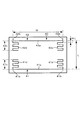
Next, the present inventor created an antenna (hereinafter referred to as the antenna of the invention 1) based on the above conclusion, and compared the performance with a conventional antenna. FIG. 9 is a plan view of a conventional antenna used in the
このシミュレーションは、アンテナの上面および下面を誘電体で挾んで行った。その誘電体は、60×90mm、厚さ2.5mmおよび誘電率ε=3、誘電正接(誘電損失)tanδ=0.004@0.953GHzである。また、放射素子および反射素子の全長Wは80mmに統一し、両素子の配置間隔Lは50mmに統一した。また、メアンダ部の間隔MLは2mmに統一し、放射素子および反射素子の線幅は1mmに統一した。 In this simulation, the upper and lower surfaces of the antenna were sandwiched with a dielectric. The dielectric has a size of 60 × 90 mm, a thickness of 2.5 mm, a dielectric constant ε = 3, and a dielectric loss tangent (dielectric loss) tan δ=0.004@0.953 GHz. The total length W of the radiating element and the reflecting element was unified to 80 mm, and the arrangement interval L between both elements was unified to 50 mm. The meander interval ML was unified to 2 mm, and the line widths of the radiating element and the reflecting element were unified to 1 mm.
図9に示すように、従来のアンテナ40の放射素子41は、直線状部41aと、この直線状部41aの屈曲点41bから反射素子42に向けて屈曲され、相対向する一対の屈曲部41cとを備える。各屈曲部41cは、直線状部41aと平行な複数のメアンダ部41dを有する。反射素子42は、放射素子41と線対称の形状を呈しており、直線状部42aと、この直線状部42aの屈曲点42bから放射素子41に向けて屈曲され、相対向する一対の屈曲部42cとを備えており、各屈曲部42cは、直線状部42aと平行な複数のメアンダ部42dを有する。
As shown in FIG. 9, the radiating
図10に示すように、発明1のアンテナ20の放射素子21は、直線状部21aと、この直線状部21aの屈曲点21bから反射素子22に向けて屈曲され、相対向する一対の屈曲部21cとを備える。各屈曲部21cは、直線状部21aと平行なメアンダ部21d1,21d2,21d6を有する。反射素子22は、放射素子21と線対称の形状に形成されており、直線状部22aと、この直線状部22aの屈曲点22bから放射素子21に向けて屈曲され、相対向する一対の屈曲部22cとを備える。各屈曲部22cは、直線状部22aと平行なメアンダ部22d1,22d2,22d6を有する。
As shown in FIG. 10, the radiating
放射素子21および反射素子22において、各メアンダ部の内側へ突出している長さは、直線状部に最も近いメアンダ部および直線状部から最も遠いメアンダ部が最も短く、中央のメアンダ部が最も長くなっている。つまり、各メアンダ部の内側へ突出している長さは、直線状部から遠ざかるに従って長くなり、その途中からは直線状部から遠ざかるに従って短くなるように形成されている。最も短い相対向するメアンダ部間の間隔W1は68mmであり、最も長いメアンダ部間の間隔W2は58mmである。そして、従来のアンテナおよび発明1のアンテナの利得(損失含む)および放射効率を測定した。
In the radiating
[結果1]
その結果、アンテナの利得は、従来のアンテナが2.62dBiであったのに対し、発明1は2.68dBiであり、発明1のアンテナを使用すれば、従来よりも利得を0.06dBi高くすることができることが分かった。また、放射効率は、従来のアンテナが0.8541であったのに対し、発明1は0.8609であり、発明1のアンテナを使用すれば、従来よりも放射効率を0.0068高くすることができることが分かった。
[Result 1]
As a result, the gain of the antenna was 2.62 dBi for the conventional antenna, but 2.68 dBi for
このようにアンテナ利得を高くすることができた要因は、直線状部に近いメアンダ部を短くすることにより、直線状部との自己結合を小さくすることができたからであると推定した。また、直線状部から遠ざかるに従ってメアンダ部を長くすることにより、素子長(エレメント長)を長くすることができたこともアンテナ利得向上の要因であると推定した。 It was estimated that the reason why the antenna gain could be increased in this manner was that the self-coupling with the linear portion could be reduced by shortening the meander portion close to the linear portion. It was also estimated that the element length (element length) could be increased by lengthening the meander portion as it moved away from the linear portion, which was also a factor in improving the antenna gain.
さらに、放射素子21の直線状部21aから最も遠いメアンダ部21d6と、反射素子22の直線状部22aから最も遠いメアンダ部22d6とが接近した状態になるため、それらのメアンダ部21d6,22d6によって素子間結合が発生し易い。そこで、それらのメアンダ部21d6,22d6の突出長さを短くすることにより、素子間結合を小さくすることができたことも要因の一つであると推定した。
Furthermore, since the meander part 21d6 farthest from the
つまり、各メアンダ部は、その内側へ突出している長さが直線状部から遠ざかるに従って長くなり、その途中からは直線状部から遠ざかるに従って短くなるように形成することにより、アンテナ利得および放射効率を高めることができることが分かった。 That is, each meander part is formed such that the length protruding inward becomes longer as it goes away from the linear part, and from the middle it becomes shorter as it gets away from the linear part, thereby reducing the antenna gain and radiation efficiency. It turned out that it can raise.
[シミュレーション2]
次に、本願発明者は、メアンダ部の頂部をテーパ状に形成したアンテナ(以下、発明2のアンテナという)を作成し、シミュレーションを行った。図13は、このシミュレーション2に用いた発明2のアンテナの平面図である。図14は、発明2のアンテナのVSWR特性を示すグラフである。シミュレーションの条件は、シミュレーション1と同じである。
[Simulation 2]
Next, the inventor of the present application created an antenna in which the top of the meander portion was formed in a tapered shape (hereinafter referred to as the antenna of the invention 2), and performed a simulation. FIG. 13 is a plan view of the antenna of the
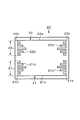
図13に示すように、発明2のアンテナ20の特徴は、発明1のアンテナ(図10)の各メアンダ部の頂部をテーパ状に形成した点である。放射素子21は、直線状部21aと、この直線状部21aの屈曲点21bから反射素子22に向けて屈曲され、相対向する一対の屈曲部21cとを備える。各屈曲部21cは、直線状部21aと平行なメアンダ部21d1,21d2,21d6を有する。直線状部21aから最も遠く、屈曲部21cの先端に形成されたメアンダ部21d6は、線状に形成されており、内側へ突出している。メアンダ部21d6は、メアンダ部の中で最も短い。
As shown in FIG. 13, the feature of the
直線状部21aに最も近いメアンダ部21d1の頂部は、屈曲点21bに向けてテーパ状に形成されている。このメアンダ部21d1に隣接するメアンダ部21d2の内側へ突出する長さは、メアンダ部21d1よりも長く、その頂部は、メアンダ部21d6に向けてテーパ状に形成されている。反射素子22は、放射素子21と線対称に形成されており、直線状部22aと、一対の屈曲部22cとを備えている。各屈曲部22cは、直線状部22aと平行なメアンダ部22d1,22d2,22d6を有する。
The top of the meander part 21d1 closest to the
また、相対向するメアンダ部22d6(21d6)間の間隔W1が74mmであり、相対向するメアンダ部22d1(21d1)間の間隔W2が64mmであり、相対向するメアンダ部22d2(21d2)間の間隔W3が54mmである。 Further, the interval W1 between the meander portions 22d6 (21d6) facing each other is 74 mm, the interval W2 between the meander portions 22d1 (21d1) facing each other is 64 mm, and the interval between the meander portions 22d2 (21d2) facing each other. W3 is 54 mm.
[結果2]
シミュレーションの結果、アンテナの利得は、2.75dBiであり、従来よりも利得を0.13dBi高くすることができることが分かった。また、放射効率は、0.8724であり、従来よりも放射効率を0.0183高くすることができることが分かった。
[Result 2]
As a result of simulation, it has been found that the gain of the antenna is 2.75 dBi, and the gain can be increased by 0.13 dBi compared to the conventional case. Also, the radiation efficiency was 0.8724, and it was found that the radiation efficiency can be increased by 0.0183 compared to the conventional case.
このように、発明2のアンテナが、発明1のアンテナよりもアンテナ利得を高くすることができた要因は、各メアンダ部の頂部をテーパ状に形成することにより、素子長(エレメント長)を長くすることができたからであると推定した。
As described above, the antenna gain of the antenna of the
つまり、各メアンダ部は、その内側へ突出している長さが直線状部から遠ざかるに従って長くなり、その途中からは直線状部から遠ざかるに従って短くなるように形成し、かつ、各メアンダの頂部をテーパ状に形成すると、アンテナ利得および放射効率をより一層高めることができることが分かった。 That is, each meander part is formed such that the length protruding inward becomes longer as it goes away from the linear part, and from the middle it becomes shorter as it goes away from the linear part, and the top part of each meander is tapered. It has been found that the antenna gain and the radiation efficiency can be further increased by forming in the shape.
[シミュレーション3]
次に、本願発明者は、上記の結果2を基に、放射素子および反射素子の全長W、両素子の配置間隔Lおよびメアンダ部の間隔MLを変更して再度シミュレーションを行った。図15は、従来のアンテナの測定結果をまとめて示す図表であり、図16は、発明2のアンテナの測定結果をまとめて示す図表である。
[Simulation 3]
Next, the inventor of the present application changed the overall length W of the radiating element and the reflecting element, the arrangement interval L of both elements, and the interval ML of the meander part based on the
[結果3]
図15および図16に示すように、放射素子および反射素子の全長W、両素子の配置間隔Lおよびメアンダ部の間隔MLを変更した場合でも、発明2のアンテナは、従来のアンテナよりもアンテナ利得および放射効率(VSWR)を高くすることができることが分かった。
[Result 3]
As shown in FIGS. 15 and 16, even when the total length W of the radiating element and the reflecting element, the arrangement interval L between both elements, and the interval ML between the meander portions are changed, the antenna of the
[結論]
上述の結果1ないし3から、各メアンダ部は、その内側へ突出している長さが直線状部から遠ざかるに従って長くなり、その途中からは直線状部から遠ざかるに従って短くなるように形成し、かつ、各メアンダ部の頂部が、その頂部を成す辺と直線状部とが成す角度が鋭角になるテーパ状に形成することにより、アンテナ利得および放射効率を高めることができる。
[Conclusion]
From the
その後、本願発明者は、さらに研究を重ね、発明2のアンテナにおけるメアンダ部の数を増やすことにより、素子長を長くし、アンテナ利得および放射効率をより一層高めることのできるアンテナ20(図4)を開発した。
Thereafter, the inventor of the present application further researched, and by increasing the number of meander portions in the antenna of the
[変更例]
(1)図17は、第1実施形態の変更例に係るタグリーダに備えられたアンテナの説明図である。このアンテナは、放射素子21のメアンダ部21dおよび反射素子22のメアンダ部22dの各頂部が、それぞれ内側に膨らんだテーパ曲面状に形成されてなることを特徴としている。メアンダ部の頂部以外は、前述した第1実施形態のアンテナ20(図4)と同一である。
[Example of change]
(1) FIG. 17 is an explanatory diagram of an antenna provided in a tag reader according to a modification of the first embodiment. This antenna is characterized in that the top portions of the
放射素子21の左側の屈曲部21cを例にして説明すると、図17(b)に示すように、メアンダ部21d1〜21d5の各頂部21eは、内側に膨らんだテーパ曲面状に形成されている。
本願発明者は、上記のように、各メアンダ部の頂部を内側に膨らんだテーパ曲面状に形成することにより、直線状部およびメアンダ部間の自己結合を小さくすることができると推定した。
The left
As described above, the inventor of the present application estimated that the self-coupling between the linear portion and the meander portion can be reduced by forming the top portion of each meander portion into a tapered curved surface swelled inward.
(2)図18は、アンテナの変更例を示す説明図である。放射素子21の各メアンダ部21dは、直線状部21aに対して非平行に形成されており、反射素子22に近付く方向に延びている。また、反射素子22の各メアンダ部22dは、直線状部22aに対して非平行に形成されており、放射素子21に近付く方向に延びている。本願発明者は、上記のように、各メアンダ部を形成することにより、メアンダ部と直線状部との距離を長くすることができるため、メアンダ部および直線状部間の自己結合を小さくすることができると推定した。
(2) FIG. 18 is an explanatory diagram showing a modification example of the antenna. Each
(3)図19は、アンテナの変更例を示す説明図である。各メアンダ部21d,22dの頂部が、それぞれ平坦に形成されている他は、第1実施形態のアンテナ20と同じ構成である。図19に示すアンテナ20を用いた場合でも、従来のアンテナよりもアンテナ利得および放射効率を高めることができる。
(3) FIG. 19 is an explanatory diagram showing a modification example of the antenna. The configuration is the same as that of the
(4)また、図20に示すように、直線状部から遠ざかるに従って長くなるメアンダ部を有するアンテナを用いることもできる。このアンテナを用いた場合でも、従来のアンテナよりもアンテナ利得および放射効率を高めることができる。 (4) Moreover, as shown in FIG. 20, an antenna having a meander part that becomes longer as it gets away from the linear part can be used. Even when this antenna is used, the antenna gain and the radiation efficiency can be increased as compared with the conventional antenna.
(5)さらに、図21に示すように、3素子の八木アンテナを用いることもできる。アンテナ20は、放射素子21、導波素子23および反射素子22の3素子から構成されている。放射素子21のメアンダ部21dは、直線状部21aから遠ざかるに従って長くなり、その途中からは、直線状部21aから遠ざかるに従って短くなるように形成されている。
(5) Furthermore, as shown in FIG. 21, a 3-element Yagi antenna can also be used. The
反射素子22のメアンダ部22dは、直線状部22aから遠ざかるに従って長くなるように形成されている。導波素子23は、直線状部23aと、この直線状部23aの両端の屈曲点23bから放射方向(図中白抜きの矢印で示す方向)に向けて屈曲され、相対向する一対の屈曲部23cとを備えている。各屈曲部23cは、直線状部23aから遠ざかるに従って長くなる複数のメアンダ部23dを有する。この3素子の八木アンテナを用いた場合も、従来のアンテナよりもアンテナ利得および放射効率を高めることができる。
The
(6)アンテナ20は、放射素子および導波素子の2素子構成にすることもできる。この構成においても各素子のメアンダ部を上述した第1実施形態および各変更例のように形成することにより、従来のアンテナよりもアンテナ利得および放射効率を高めることができる。反射素子および導波素子を無給電素子とすると、その無給電素子および放射素子の2素子構成のアンテナでは、無給電素子の素子長が所定の長さ(たとえば、約0.48λ)までは導波素子として動作し、所定の長さ以上になると、主放射方向が反転して反射素子として動作する。また、無給電素子を反射素子として動作させた方が、導波素子として動作させた場合よりも、利得およびFB比を高くすることができる。
(6) The
(7)前述した2素子構成または3素子構成において、各素子の屈曲部は、直線状部の両端から電波の送信方向へ向けて形成しても良いし、電波の受信方向へ向けて形成しても良い。この構成を用いた場合も第1実施形態および各変更例と同じ効果を奏することができる。 (7) In the two-element configuration or the three-element configuration described above, the bent portion of each element may be formed from both ends of the linear portion toward the radio wave transmission direction or toward the radio wave reception direction. May be. Even when this configuration is used, the same effects as those of the first embodiment and the modified examples can be obtained.
〈第2実施形態〉
次に、この発明の第2実施形態について説明する。この実施形態に係るタグリーダは、ダイポールアンテナを備えたことを特徴とする。図22は、ダイポールアンテナの平面説明図である。
Second Embodiment
Next explained is the second embodiment of the invention. The tag reader according to this embodiment includes a dipole antenna. FIG. 22 is an explanatory plan view of a dipole antenna.
ダイポールアンテナ30は、給電線に接続された直線状部30aと、この直線状部30aの両端の屈曲点30bから屈曲され、相対向する一対の屈曲部30cとを備えている。各屈曲部30cは、直線状部30aから遠ざかるに従って長く形成された複数のメアンダ部30dを備えている。また、各メアンダ部30dの頂部は、屈曲点30bに向けて傾斜したテーパ状に形成されている。
The
本願発明者は、第1実施形態のシミュレーション1〜3の結果1〜3に基づき、上記のダイポールアンテナ30の場合も同様に、従来のダイポールアンテナよりもアンテナ利得および放射効率を高めることができるものと推定した。
Based on the
[変更例]
(1)図23に示すように、メアンダ部30dの頂部を、内側に膨らんだテーパ曲面状に形成することもできる。この構成のダイポールアンテナ30を用いれば、直線状部30aおよび各メアンダ部30d間の自己結合を小さくすることができるため、アンテナ利得をより一層高くすることができる。
[Example of change]
(1) As shown in FIG. 23, the top part of the
(2)図24に示すように、各メアンダ部30dの頂部を平坦に形成することもできる。この構成のダイポールアンテナ30を用いた場合も、従来のアンテナよりもアンテナ利得および放射効率を高めることができる。また、各メアンダ部30dを、直線状部30aから遠ざかるに従って長くなり、その途中からは、直線状部30aから遠ざかるに従って短くなるように形成することもできる。この構成を用いれば、アンテナよりもアンテナ利得および放射効率をより一層高めることができる。
(2) As shown in FIG. 24, the top of each
1・・タグリーダ(RFIDタグ読取装置)、20・・アンテナ、
21・・放射素子、22・・反射素子、21a,22a・・直線状部、
21c,22c・・屈曲部、21d,22d・・メアンダ部(折り返された部分)、
23・・導波素子、30・・ダイポールアンテナ、30a・・直線状部、
30c・・屈曲部、30d・・メアンダ部(折り返された部分)。
1..Tag reader (RFID tag reader), 20..Antenna,
21 .. Radiation element, 22 .. Reflection element, 21a, 22a.
21c, 22c ·· bent portion, 21d, 22d · · meander portion (folded portion),
23 .. Waveguide element, 30... Dipole antenna, 30 a.
30c ·· bent portion, 30d ·· meander portion (folded portion).
Claims (9)
前記ダイポールアンテナを構成する素子は、
給電線に接続された直線状部と、
前記直線状部の両端から互いに同じ側に屈曲され、相対向する一対の屈曲部とを備えており、
前記一対の屈曲部は、それぞれ複数回折り返されたメアンダ状に形成されており、かつ、メアンダ状の部分のうち、少なくとも前記直線状部の両端から所定範囲において、前記折り返された部分が前記直線状部から遠ざかるに従って長くなるように形成されてなり、それら前記折り返された部分は、それぞれの外側の端部が、前記直線状部と直交し且つ当該直線状部の端部を通る直交線上に位置していることを特徴とするRFIDタグ読取装置。 In an RFID tag reader configured to read information recorded on an RFID tag by communicating with the RFID tag by radio waves via a dipole antenna,
The elements constituting the dipole antenna are
A straight section connected to the feeder line;
A pair of bent portions that are bent from the both ends of the linear portion to the same side and are opposed to each other;
The pair of bent portions are each formed in a meander shape that is folded back multiple times, and among the meander portions, at least a predetermined range from both ends of the linear portion, the folded portions are the straight lines. The folded portions are formed so that the outer ends thereof are orthogonal to the linear portion and pass through the end portions of the linear portion. An RFID tag reader characterized by being located .
前記放射素子、導波素子および反射素子の少なくとも1つが、
直線状部と、
前記直線状部の両端から他のいずれかの素子に向けて互いに同じ側に屈曲され、相対向する一対の屈曲部とを備えており、
前記一対の屈曲部は、それぞれ複数回折り返されたメアンダ状に形成されており、かつ、各メアンダ状の部分のうち、少なくとも前記直線状部の両端から所定範囲において、前記折り返された部分が前記直線状部から遠ざかるに従って長くなるように形成されてなり、それら前記折り返された部分は、それぞれの外側の端部が、前記直線状部と直交し且つ当該直線状部の端部を通る直交線上に位置していることを特徴とするRFIDタグ読取装置。 In an RFID tag reader configured to read information recorded on an RFID tag by communicating with the RFID tag by radio waves via an antenna having a radiating element, a waveguide element and a reflecting element,
At least one of the radiating element, the waveguide element, and the reflecting element,
A linear section;
A pair of bent portions that are bent on the same side from both ends of the linear portion toward one of the other elements, and are opposed to each other,
The pair of bent portions are each formed in a meander shape that is folded back multiple times, and among the meander-shaped portions, at least in a predetermined range from both ends of the linear portion, the folded portions are The folded portions are formed so as to become longer as they move away from the linear portion , and the outer ends of the folded portions are on orthogonal lines that are orthogonal to the linear portions and pass through the ends of the linear portions. An RFID tag reader characterized by being located in
前記放射素子および導波素子の少なくとも一方が、
直線状部と、
前記直線状部の両端から他方の素子に向けて互いに同じ側に屈曲され、相対向する一対の屈曲部とを備えており、
前記一対の屈曲部は、それぞれ複数回折り返されたメアンダ状に形成されており、かつ、各メアンダ状の部分のうち、少なくとも前記直線状部の両端から所定範囲において、前記折り返された部分が前記直線状部から遠ざかるに従って長くなるように形成されてなり、それら前記折り返された部分は、それぞれの外側の端部が、前記直線状部と直交し且つ当該直線状部の端部を通る直交線上に位置していることを特徴とするRFIDタグ読取装置。 In an RFID tag reader configured to read information recorded in an RFID tag by communicating with the RFID tag by radio waves via an antenna having a radiating element and a waveguide element,
At least one of the radiating element and the waveguide element is
A linear section;
A pair of bent portions that are bent on the same side from both ends of the linear portion toward the other element, and facing each other ;
The pair of bent portions are each formed in a meander shape that is folded back multiple times, and among the meander-shaped portions, at least in a predetermined range from both ends of the linear portion, the folded portions are The folded portions are formed so as to become longer as they move away from the linear portion , and the outer ends of the folded portions are on orthogonal lines that are orthogonal to the linear portions and pass through the ends of the linear portions. An RFID tag reader characterized by being located in
前記放射素子および反射素子の少なくとも一方が、
直線状部と、
前記直線状部の両端から他方の素子に向けて互いに同じ側に屈曲され、相対向する一対の屈曲部とを備えており、
前記一対の屈曲部は、それぞれ複数回折り返されたメアンダ状に形成されており、かつ、各メアンダ状の部分のうち、少なくとも前記直線状部の両端から所定範囲において、前記折り返された部分が前記直線状部から遠ざかるに従って長くなるように形成されてなり、それら前記折り返された部分は、それぞれの外側の端部が、前記直線状部と直交し且つ当該直線状部の端部を通る直交線上に位置していることを特徴とするRFIDタグ読取装置。 In an RFID tag reader configured to read information recorded in an RFID tag by communicating with the RFID tag by radio waves via an antenna having a radiating element and a reflective element,
At least one of the radiating element and the reflecting element is
A linear section;
A pair of bent portions that are bent on the same side from both ends of the linear portion toward the other element, and facing each other ;
The pair of bent portions are each formed in a meander shape that is folded back multiple times, and among the meander-shaped portions, at least in a predetermined range from both ends of the linear portion, the folded portions are The folded portions are formed so as to become longer as they move away from the linear portion , and the outer ends of the folded portions are on orthogonal lines that are orthogonal to the linear portions and pass through the ends of the linear portions. An RFID tag reader characterized by being located in
前記各屈曲部は、それぞれ複数回折り返されてメアンダ状に形成されており、かつ、各メアンダ状の部分のうち、少なくとも前記直線状部の両端から所定範囲において、前記折り返された部分が前記直線状部から遠ざかるに従って長くなるように形成されてなることを特徴とする請求項3または請求項4に記載のRFIDタグ読取装置。 The radiating element and an element other than the radiating element each include the linear portion and a pair of bent portions,
Each of the bent portions is formed in a meander shape by being folded back multiple times, and among the meander portions, at least in a predetermined range from both ends of the linear portion, the folded portion is the straight line. 5. The RFID tag reader according to claim 3, wherein the RFID tag reader is formed so as to become longer as the distance from the shape portion increases.
少なくとも前記所定範囲において、前記折り返された部分が前記直線状部から遠ざかるに従って長くなり、その途中からは、前記直線状部から遠ざかるに従って短くなるように形成されてなることを特徴とする請求項1ないし請求項5のいずれか1つに記載のRFIDタグ読取装置。 At least one meander portion of each meander portion is:
2. At least in the predetermined range, the folded portion is formed so as to become longer as the distance from the linear portion increases, and from the middle thereof, the folded portion becomes shorter as the distance from the linear portion increases. The RFID tag reader according to claim 5.
少なくとも前記所定範囲において内側を向いて山状に形成されている部分の頂部が、その頂部を成す辺と前記直線状部とが成す角度が鋭角になるテーパ状に形成されてなることを特徴とする請求項1ないし請求項6のいずれか1つに記載のRFIDタグ読取装置。 At least one meander portion of each meander portion is:
The top of the portion formed in a mountain shape facing inward in at least the predetermined range is formed in a taper shape in which the angle formed between the side forming the top and the linear portion is an acute angle. The RFID tag reader according to any one of claims 1 to 6.
少なくとも前記所定範囲が前記直線状部に対して非平行に形成されてなることを特徴とする請求項1ないし請求項8のいずれか1つに記載のRFIDタグ読取装置。 At least one meander portion of each meander portion is:
9. The RFID tag reader according to claim 1, wherein at least the predetermined range is formed non-parallel to the linear portion.
Priority Applications (1)
| Application Number | Priority Date | Filing Date | Title |
|---|---|---|---|
| JP2009105873A JP5218251B2 (en) | 2009-04-24 | 2009-04-24 | RFID tag reader |
Applications Claiming Priority (1)
| Application Number | Priority Date | Filing Date | Title |
|---|---|---|---|
| JP2009105873A JP5218251B2 (en) | 2009-04-24 | 2009-04-24 | RFID tag reader |
Publications (2)
| Publication Number | Publication Date |
|---|---|
| JP2010258731A JP2010258731A (en) | 2010-11-11 |
| JP5218251B2 true JP5218251B2 (en) | 2013-06-26 |
Family
ID=43319153
Family Applications (1)
| Application Number | Title | Priority Date | Filing Date |
|---|---|---|---|
| JP2009105873A Expired - Fee Related JP5218251B2 (en) | 2009-04-24 | 2009-04-24 | RFID tag reader |
Country Status (1)
| Country | Link |
|---|---|
| JP (1) | JP5218251B2 (en) |
Families Citing this family (4)
| Publication number | Priority date | Publication date | Assignee | Title |
|---|---|---|---|---|
| JP2012227579A (en) * | 2011-04-15 | 2012-11-15 | Funai Electric Co Ltd | Multi-antenna device and communication apparatus |
| JP6131816B2 (en) * | 2013-10-07 | 2017-05-24 | 株式会社デンソー | Modified folded dipole antenna |
| DE212018000053U1 (en) * | 2017-07-14 | 2019-01-14 | Murata Manufacturing Co., Ltd. | RFID tag |
| JP6424995B1 (en) * | 2017-07-14 | 2018-11-21 | 株式会社村田製作所 | RFID tag |
Family Cites Families (8)
| Publication number | Priority date | Publication date | Assignee | Title |
|---|---|---|---|---|
| US2647211A (en) * | 1949-01-11 | 1953-07-28 | Lynne C Smeby | Radio antenna |
| GB927051A (en) * | 1959-10-07 | 1963-05-22 | Rudolf Guertler | Improvements in or relating to antennas for high frequencies |
| JP3296189B2 (en) * | 1996-06-03 | 2002-06-24 | 三菱電機株式会社 | Antenna device |
| GB2330951B (en) * | 1997-11-04 | 2002-09-18 | Nokia Mobile Phones Ltd | Antenna |
| JP3554960B2 (en) * | 1999-06-25 | 2004-08-18 | 株式会社村田製作所 | Antenna device and communication device using the same |
| JP2003198410A (en) * | 2001-12-27 | 2003-07-11 | Matsushita Electric Ind Co Ltd | Antenna for communication terminal device |
| JP4850025B2 (en) * | 2006-10-23 | 2012-01-11 | シャープ株式会社 | Communication device |
| JP2008113462A (en) * | 2007-12-17 | 2008-05-15 | Fractus Sa | Coupled multiband antenna |
-
2009
- 2009-04-24 JP JP2009105873A patent/JP5218251B2/en not_active Expired - Fee Related
Also Published As
| Publication number | Publication date |
|---|---|
| JP2010258731A (en) | 2010-11-11 |
Similar Documents
| Publication | Publication Date | Title |
|---|---|---|
| JP4451125B2 (en) | Small antenna | |
| US7324058B2 (en) | Tag antenna, tag and RFID system using the same | |
| JP5086004B2 (en) | Tag antenna and tag | |
| KR100680711B1 (en) | The small planar antenna with enhanced bandwidth and the small rectenna for RFID and wireless sensor transponders | |
| EP2330684B1 (en) | Rfid tag, rfid tag set and rfid system | |
| JP4026080B2 (en) | Antenna and RFID tag | |
| JP5043656B2 (en) | Tag antenna and tag | |
| JP5327334B2 (en) | Communication terminal and information processing system | |
| US8215561B2 (en) | Antenna and reader/writer device | |
| US8077115B2 (en) | Antenna device, radio tag reader and article management system | |
| JP4333555B2 (en) | RFID tag | |
| WO2007013167A1 (en) | Rf tag and rf tag manufacturing method | |
| JP2005244778A (en) | Miniaturized antenna and wireless tag provided with the same | |
| WO2007013168A1 (en) | Rf tag and rf tag manufacturing method | |
| KR20080042662A (en) | Rfid tag read system and method of reading rfid tag | |
| JP5218251B2 (en) | RFID tag reader | |
| JP2007081632A (en) | Radio ic tag | |
| EP2212832B1 (en) | A radio frequency transponder and radio frequency identification system | |
| EP1860728A1 (en) | Antenna and rfid tag | |
| EP3549067B1 (en) | Improving performance of rfid tags | |
| JP5489978B2 (en) | RFID reader / writer antenna | |
| CN209088065U (en) | A kind of RFID washing mark label antenna and RFID wash mark label | |
| JP6746058B2 (en) | Wireless IC tag device and wireless IC tag built-in device | |
| JP5112192B2 (en) | Antenna and RFID reader | |
| JP2007221735A (en) | S-shaped plate-like small-sized dipole antenna for electronic tag, and electronic tag provided with the same |
Legal Events
| Date | Code | Title | Description |
|---|---|---|---|
| A621 | Written request for application examination |
Free format text: JAPANESE INTERMEDIATE CODE: A621 Effective date: 20110822 |
|
| A977 | Report on retrieval |
Free format text: JAPANESE INTERMEDIATE CODE: A971007 Effective date: 20120808 |
|
| A131 | Notification of reasons for refusal |
Free format text: JAPANESE INTERMEDIATE CODE: A131 Effective date: 20120821 |
|
| A521 | Request for written amendment filed |
Free format text: JAPANESE INTERMEDIATE CODE: A523 Effective date: 20121022 |
|
| TRDD | Decision of grant or rejection written | ||
| A01 | Written decision to grant a patent or to grant a registration (utility model) |
Free format text: JAPANESE INTERMEDIATE CODE: A01 Effective date: 20130205 |
|
| A61 | First payment of annual fees (during grant procedure) |
Free format text: JAPANESE INTERMEDIATE CODE: A61 Effective date: 20130218 |
|
| FPAY | Renewal fee payment (event date is renewal date of database) |
Free format text: PAYMENT UNTIL: 20160315 Year of fee payment: 3 |
|
| R150 | Certificate of patent or registration of utility model |
Ref document number: 5218251 Country of ref document: JP Free format text: JAPANESE INTERMEDIATE CODE: R150 Free format text: JAPANESE INTERMEDIATE CODE: R150 |
|
| R250 | Receipt of annual fees |
Free format text: JAPANESE INTERMEDIATE CODE: R250 |
|
| R250 | Receipt of annual fees |
Free format text: JAPANESE INTERMEDIATE CODE: R250 |
|
| R250 | Receipt of annual fees |
Free format text: JAPANESE INTERMEDIATE CODE: R250 |
|
| R250 | Receipt of annual fees |
Free format text: JAPANESE INTERMEDIATE CODE: R250 |
|
| R250 | Receipt of annual fees |
Free format text: JAPANESE INTERMEDIATE CODE: R250 |
|
| R250 | Receipt of annual fees |
Free format text: JAPANESE INTERMEDIATE CODE: R250 |
|
| LAPS | Cancellation because of no payment of annual fees |