JP5216632B2 - Fluid control device - Google Patents
Fluid control device Download PDFInfo
- Publication number
- JP5216632B2 JP5216632B2 JP2009049045A JP2009049045A JP5216632B2 JP 5216632 B2 JP5216632 B2 JP 5216632B2 JP 2009049045 A JP2009049045 A JP 2009049045A JP 2009049045 A JP2009049045 A JP 2009049045A JP 5216632 B2 JP5216632 B2 JP 5216632B2
- Authority
- JP
- Japan
- Prior art keywords
- fluid control
- fluid
- valves
- flow rate
- inlet
- Prior art date
- Legal status (The legal status is an assumption and is not a legal conclusion. Google has not performed a legal analysis and makes no representation as to the accuracy of the status listed.)
- Active
Links
Images

Classifications
-
- G—PHYSICS
- G05—CONTROLLING; REGULATING
- G05D—SYSTEMS FOR CONTROLLING OR REGULATING NON-ELECTRIC VARIABLES
- G05D7/00—Control of flow
- G05D7/06—Control of flow characterised by the use of electric means
- G05D7/0617—Control of flow characterised by the use of electric means specially adapted for fluid materials
-
- C—CHEMISTRY; METALLURGY
- C23—COATING METALLIC MATERIAL; COATING MATERIAL WITH METALLIC MATERIAL; CHEMICAL SURFACE TREATMENT; DIFFUSION TREATMENT OF METALLIC MATERIAL; COATING BY VACUUM EVAPORATION, BY SPUTTERING, BY ION IMPLANTATION OR BY CHEMICAL VAPOUR DEPOSITION, IN GENERAL; INHIBITING CORROSION OF METALLIC MATERIAL OR INCRUSTATION IN GENERAL
- C23C—COATING METALLIC MATERIAL; COATING MATERIAL WITH METALLIC MATERIAL; SURFACE TREATMENT OF METALLIC MATERIAL BY DIFFUSION INTO THE SURFACE, BY CHEMICAL CONVERSION OR SUBSTITUTION; COATING BY VACUUM EVAPORATION, BY SPUTTERING, BY ION IMPLANTATION OR BY CHEMICAL VAPOUR DEPOSITION, IN GENERAL
- C23C16/00—Chemical coating by decomposition of gaseous compounds, without leaving reaction products of surface material in the coating, i.e. chemical vapour deposition [CVD] processes
- C23C16/44—Chemical coating by decomposition of gaseous compounds, without leaving reaction products of surface material in the coating, i.e. chemical vapour deposition [CVD] processes characterised by the method of coating
- C23C16/455—Chemical coating by decomposition of gaseous compounds, without leaving reaction products of surface material in the coating, i.e. chemical vapour deposition [CVD] processes characterised by the method of coating characterised by the method used for introducing gases into reaction chamber or for modifying gas flows in reaction chamber
- C23C16/45561—Gas plumbing upstream of the reaction chamber
-
- H—ELECTRICITY
- H10—SEMICONDUCTOR DEVICES; ELECTRIC SOLID-STATE DEVICES NOT OTHERWISE PROVIDED FOR
- H10P—GENERIC PROCESSES OR APPARATUS FOR THE MANUFACTURE OR TREATMENT OF DEVICES COVERED BY CLASS H10
- H10P72/00—Handling or holding of wafers, substrates or devices during manufacture or treatment thereof
- H10P72/04—Apparatus for manufacture or treatment
- H10P72/0402—Apparatus for fluid treatment
-
- Y—GENERAL TAGGING OF NEW TECHNOLOGICAL DEVELOPMENTS; GENERAL TAGGING OF CROSS-SECTIONAL TECHNOLOGIES SPANNING OVER SEVERAL SECTIONS OF THE IPC; TECHNICAL SUBJECTS COVERED BY FORMER USPC CROSS-REFERENCE ART COLLECTIONS [XRACs] AND DIGESTS
- Y10—TECHNICAL SUBJECTS COVERED BY FORMER USPC
- Y10T—TECHNICAL SUBJECTS COVERED BY FORMER US CLASSIFICATION
- Y10T137/00—Fluid handling
- Y10T137/0318—Processes
- Y10T137/0396—Involving pressure control
Landscapes
- Chemical & Material Sciences (AREA)
- Engineering & Computer Science (AREA)
- Metallurgy (AREA)
- Chemical Kinetics & Catalysis (AREA)
- Materials Engineering (AREA)
- Mechanical Engineering (AREA)
- General Chemical & Material Sciences (AREA)
- Organic Chemistry (AREA)
- Physics & Mathematics (AREA)
- General Physics & Mathematics (AREA)
- Automation & Control Theory (AREA)
- Flow Control (AREA)
- Chemical Vapour Deposition (AREA)
- Valve Housings (AREA)
Description
この発明は、半導体製造装置等に使用される流体制御装置に関し、特に、複数の流体制御機器が集積化されて形成される流体制御装置に関する。 The present invention relates to a fluid control device used in a semiconductor manufacturing apparatus or the like, and more particularly to a fluid control device formed by integrating a plurality of fluid control devices.
半導体製造装置で使用される流体制御装置においては、複数の流体制御機器が直列状に配されてパイプや継手を介さずに接続されることによって形成された複数のラインをベース部材上に並列状に設置するという集積化が進んでいる(特許文献1および特許文献2)。
In a fluid control device used in a semiconductor manufacturing apparatus, a plurality of fluid control devices are arranged in series, and a plurality of lines formed by connecting them without using pipes or joints are arranged in parallel on a base member. Integration is proceeding to be installed in (
特許文献1の流体制御装置においては、図7に示すように、1つの流量制御器(21)を基本構成要素として1列のプロセスガス制御ライン(流体制御ライン)が構成され、複数(流量制御器(21)の数と同じ)のプロセスガス制御ラインL1〜L16が並列に配置されることで、流体制御装置が構成されている。流体制御ラインL1〜L16にさらに並列に追加されているラインPは、パージガスラインである。
In the fluid control device of
図7において、各プロセスガス制御ラインL1〜L16は、入口側から、フィルタ(24)、入口側の2つの開閉弁(23)、流量制御器(マスフローコントローラ)(21)および出口側の開閉弁(25)を有しており、各プロセスガス制御ラインL1〜L16に共通の出口部分にも、開閉弁(26)が設けられている。 7, each process gas control line L1 to L16 includes, from the inlet side, a filter (24), two on-off valves (23) on the inlet side, a flow rate controller (mass flow controller) (21), and an on-off valve on the outlet side. (25), and an on-off valve (26) is provided at an outlet common to the process gas control lines L1 to L16.
このような流体制御装置においては、全てのプロセスガス制御ラインL1〜L16に常に流体(ガス)が流されているわけではなく、2〜3ラインを使用して、異なる種類や異なる流量のガスが順次切り換えられ、流量調整器(21)によってその流量が調整されて、下流側のチャンバーへと送られる。流量調整器(21)として使用されるマスフローコントローラは、流量センサおよびコントロール弁などを内蔵したもので、高価でかつ頻繁なメンテナンスが必要であり、全体のコストを増加させる要因となっている。一方、半導体製造装置で使用される流体制御装置では、流体種類が増加する傾向にあり、それに伴って、スペースおよびコストが増加するという問題がある。 In such a fluid control device, fluids (gases) are not always flown through all the process gas control lines L1 to L16, and different types and different flow rates of gas are generated using two to three lines. The flow rate is sequentially switched, and the flow rate is adjusted by the flow rate regulator (21), and sent to the downstream chamber. The mass flow controller used as the flow rate regulator (21) includes a flow rate sensor and a control valve, and is expensive and requires frequent maintenance, which increases the overall cost. On the other hand, in the fluid control device used in the semiconductor manufacturing apparatus, there is a problem that the type of fluid tends to increase, and accordingly, there is a problem that space and cost increase.
また、特許文献2の流体制御装置においては、1つの流量制御器を基本構成要素として入口および出口を1つずつ有する1列の流体制御ラインがM列配置された流体制御部と、複数の開閉弁によって入口数がN(>M)で出口数がMとなるように構成された流体導入部とを有し、流体導入部のM個の出口と流体制御部のM個の入口とがそれぞれ1:1で接続されている。
Further, in the fluid control device of
この特許文献2のものを図7に示した従来の流体制御装置に対応させると、図6に示すように、M個(図示は8個)の流量制御器(21)を基本構成要素とする流体制御ラインL1〜L8がM列配置された流体制御部(2)と、複数の開閉弁(23)によって入口数がN(図示は16個)で出口数がMとなるように構成された流体導入部(3)とを有しているものとなる。
If the thing of this
同図において、各流体制御ラインL1〜L8は、プロセスガスを制御するラインであり、これらに並列となるように、1列のパージガスラインPが設けられている。 In the same figure, each fluid control line L1-L8 is a line which controls process gas, and the purge gas line P of 1 row is provided so that it may be parallel to these.
流量制御器(21)としては、マスフローコントローラが使用されている。マスフローコントローラ(21)は、流量調整可能範囲が比較的狭いため、同じ種類の流体であってもその流量調整範囲が異なる場合には別のマスフローコントローラ(21)が使用されており、M列の流体制御ラインL1〜L8によって、M種類のプロセスガス(同じプロセスガスで流量が異なるものを含む)の流量を調整することができる。 A mass flow controller is used as the flow rate controller (21). The mass flow controller (21) has a relatively narrow flow rate adjustable range, so if the flow rate adjustment range is different even for the same type of fluid, another mass flow controller (21) is used. The fluid control lines L1 to L8 can adjust the flow rates of M types of process gases (including the same process gas but different flow rates).
流体導入部(3)は、N×M個の開閉弁(23)からなり、流体導入部(3)のM個の出口と流体制御部(2)のM個の入口とは、それぞれ1:1に対応するように接続されている。 The fluid introduction part (3) comprises N × M on-off valves (23), and the M outlets of the fluid introduction part (3) and the M inlets of the fluid control part (2) are respectively 1: 1 so as to correspond to 1.
流体導入部(3)のN個の各入口には、フィルタ(24)および手動弁(27)がそれぞれ設けられている。M列の各流体制御ラインL1〜L8には、それぞれ2つの出口側開閉弁(25)が設けられている。また、流体制御部(2)の出口側には、各流体制御ラインL1〜L8に共通の圧力スイッチ(28)、フィルタ(24)および開閉弁(26)が設けられている。 A filter (24) and a manual valve (27) are provided at each of the N inlets of the fluid introduction part (3). Each of the M rows of fluid control lines L1 to L8 is provided with two outlet-side on-off valves (25). In addition, a pressure switch (28), a filter (24), and an on-off valve (26) common to the fluid control lines L1 to L8 are provided on the outlet side of the fluid control unit (2).
なお、流量制御器としては、マスフローコントローラの他に、圧力式のものも知られている(特許文献3参照)。 In addition to the mass flow controller, a pressure type is also known as a flow rate controller (see Patent Document 3).
上記の図6に示す流体制御装置によると、図7に示す流体制御装置に比べて、相対的にコストが高くメンテナンスが面倒な流量制御器(21)を含む流体制御ラインが16列(N列)から8列(M列)に減らされるという利点があるが、開閉弁(23)の数が大幅に増加するため、入口の数を多くしたい場合には、利点が十分に生かされないという問題がある。 According to the fluid control device shown in FIG. 6, there are 16 rows (N rows) of fluid control lines including the flow rate controller (21) which is relatively expensive and troublesome to maintain compared to the fluid control device shown in FIG. ) Is reduced to 8 rows (M rows), but the number of on-off valves (23) is greatly increased, so if you want to increase the number of inlets, the advantage is not fully utilized is there.
この発明の目的は、コストを減少するとともに、スペースの減少も可能とした流体制御装置を提供することにある。 An object of the present invention is to provide a fluid control apparatus that can reduce costs and space.
この発明による流体制御装置は、1つの流量制御器を基本構成要素として入口および出口を1つずつ有する1列の流体制御ラインがM列配置された流体制御部と、複数の開閉弁によって入口数がN(>M)で出口数がMとなるように構成された流体導入部とを有し、流体導入部のM個の出口と流体制御部のM個の入口とがそれぞれ1:1で接続されている流体制御装置において、流体導入部は、複数の開閉弁からなり入口側に配置されて入口の総数がN個で出口の総数がK個である入口側遮断開放部と、複数の開閉弁からなり入口側遮断開放部と流体制御部との間に配置されて入口の総数がK個で出口の総数がM個である流体制御部側遮断開放部とに分けられるとともに、入口側遮断開放部は、それぞれ2以上の所要数の開閉弁を有する複数のグループに分けられていることを特徴とするものである。 The fluid control apparatus according to the present invention includes a fluid control unit in which M rows of fluid control lines each having one inlet and one outlet each having one flow rate controller as a basic component are arranged, and a plurality of on-off valves. Is N (> M) and the number of outlets is M, and M outlets of the fluid inlet and M inlets of the fluid controller are 1: 1 respectively. In the connected fluid control device, the fluid introduction unit includes a plurality of on-off valves and is arranged on the inlet side, the total number of inlets is N and the total number of outlets is K. It is composed of an on-off valve and is arranged between the inlet-side shut-off part and the fluid control part, and is divided into a fluid control part-side shut-off part with a total number of inlets of K and a total number of outlets of M. A plurality of shut-off parts each having a required number of on-off valves of 2 or more And it is characterized in that it is divided into groups.
この流体制御装置は、入口数がN個、出口数がM個であり、M列の流体制御ライン(例えばL1〜L8)を使用してN種類の流体の流量を調整することができる。 This fluid control device has N inlets and M outlets, and can adjust the flow rates of N types of fluids using M rows of fluid control lines (for example, L1 to L8).
1列の流体制御ラインは、流量制御器単独または流量制御器に所要の流体制御機器が接続されることで形成される。ここで、流体制御機器は、流量制御器(マスフローコントローラまたは流体可変型流量制御装置)以外の流体制御装置構成要素を意味し、流体制御機器としては、開閉弁(流体通路の遮断・開放を行う弁)、減圧弁、圧力表示機、フィルタ、圧力スイッチなどが適宜使用される。流体制御装置に必要な流体制御機器は、流体導入部のN個の入口にそれぞれ設けられるものと、M列の流体制御ラインのそれぞれに設けられるものと、流体制御部の出口にM列の流体制御ラインに共通のものとして設けられるものとに分けられて、適宜な箇所に配置される。 One row of fluid control lines is formed by connecting a flow controller alone or a required fluid controller to the flow controller. Here, the fluid control device means a fluid control device component other than the flow rate controller (mass flow controller or fluid variable flow rate control device), and the fluid control device includes an open / close valve (blocks / opens the fluid passage). Valve), pressure reducing valve, pressure indicator, filter, pressure switch, and the like are used as appropriate. The fluid control devices required for the fluid control device are respectively provided at the N inlets of the fluid introduction unit, provided at each of the M rows of fluid control lines, and M rows of fluids at the outlet of the fluid control unit. They are divided into those provided as common to the control lines, and are arranged at appropriate locations.
1つの流体制御ラインは、例えば、下段層となる複数のブロック状継手部材がおねじ部材によって可動レールに取り付けられ、隣り合う継手部材にまたがるように上段層となる複数の流体制御機器および流量制御器が上方からのねじ部材によって継手部材に取り付けられたものとされる。 One fluid control line includes, for example, a plurality of block-shaped joint members, which are lower layers, attached to a movable rail by male thread members, and a plurality of fluid control devices, which are upper layers so as to straddle adjacent joint members, and flow control The container is attached to the joint member by a screw member from above.
一般的には、入口の総数がN個で出口の総数がK個である入口側遮断開放部は、N×K個の開閉弁からなるものとされ、K個で出口の総数がM個である流体制御部側遮断開放部は、K×M個の開閉弁からなるものとされるが、入口側遮断開放部がそれぞれ2以上の所要数の開閉弁を有する複数(例えば2つまたは4つ)のグループに分けられていることで、入口側遮断開放部の開閉弁の総数が、2つのグループに分けられている場合には、N×K/2個に、4つのグループに分けられている場合には、N×K/4個に減少する。 In general, the inlet-side shut-off part with a total number of N inlets and K total outlets is composed of N × K on-off valves, and the total number of K outlets is M. A certain fluid control unit-side shut-off part is composed of K × M on-off valves, but the inlet-side shut-off part has a plurality (for example, two or four) each having two or more required number of on-off valves. ), The total number of on-off valves of the inlet side shut-off part is divided into two groups, N × K / 2, and divided into four groups. If it is, the number is reduced to N × K / 4.
例えば、流体導入部は、それぞれN1×2個および(N−N1)×2個の開閉弁からなる第1および第2の入口側遮断開放部と、4×M個の開閉弁からなる流体制御部側遮断開放部とからなることがある。N1は、例えばN/2とされる。Nは入口数で、Mは出口数であり、この場合には、第1および第2入口側遮断開放部によって、入口数N個に対して出口数が4個(流体種類は、最大で各入口側遮断開放部に2種類ずつ計4種類に限定)とされ、流体制御部側遮断開放部によって4種類の流体がM個の出口のいずれかに分配される。このようにすることで、流体導入部を構成するのに必要な開閉弁の数を減少することができる。 For example, the fluid introduction part includes first and second inlet side shut-off opening parts each composed of N1 × 2 and (N−N1) × 2 on-off valves, and fluid control composed of 4 × M on-off valves. It may consist of a part-side shut-off part. N1 is, for example, N / 2. N is the number of inlets, and M is the number of outlets. In this case, the first and second inlet-side shut-off parts have four outlets for each N inlets (the maximum fluid type is The inlet side shut-off portion is limited to a total of four types, and two types of fluid are distributed to any of the M outlets by the fluid control portion side shut-off portion. By doing in this way, the number of on-off valves required for comprising a fluid introduction part can be reduced.
また、流体導入部は、N=N1+N2+N3+N4として、それぞれN1,N2,N3およびN4個の開閉弁からなる第1から第4までの入口側遮断開放部と、4×M個の開閉弁からなる流体制御部側遮断開放部とからなることがある。例えば、N1=N2=N3=N4=N/4とされる。Nは入口数で、Mは出口数であり、この場合には、第1から第4までの入口側遮断開放部によって、入口数N個に対して出口数が4個(流体種類は、最大で各入口側遮断開放部に1種類ずつ計4種類に限定)とされ、流体制御部側遮断開放部によって4種類の流体がM個の出口のいずれかに分配される。このようにすることで、流体導入部を構成するのに必要な開閉弁の数をより一層減少することができる。 In addition, the fluid introduction part is N = N1 + N2 + N3 + N4, and the fluid is composed of first to fourth inlet-side shut-off parts composed of N1, N2, N3 and N4 on-off valves and 4 × M on-off valves, respectively. It may consist of a control part side shut-off part. For example, N1 = N2 = N3 = N4 = N / 4. N is the number of inlets, and M is the number of outlets. In this case, the number of outlets is four with respect to the number of inlets N by the first to fourth inlet side shut-off parts (the fluid type is the maximum). Thus, each type is limited to four types, one for each inlet-side shut-off portion, and four types of fluid are distributed to one of the M outlets by the fluid control-side shut-open portion. By doing in this way, the number of on-off valves required for comprising a fluid introduction part can be reduced further.
また、流体導入部は、それぞれN/4個の開閉弁からなる第1から第4までの入口側遮断開放部と、それぞれ2×M/2個の開閉弁からなる第1および第2の流体制御部側遮断開放部とからなることがある。Nは入口数で、Mは出口数であり、この場合には、第1から第4までの入口側遮断開放部によって、入口数N個に対して出口数が4個(流体種類は、最大で各入口側遮断開放部に1種類ずつ計4種類に限定)とされ、第1および第2の流体制御部側遮断開放部によって4種類の流体がM個の出口のいずれかに分配される。このようにすることで、流体制御部側遮断開放部の開閉弁を減らすことができ、流体導入部を構成するのに必要な開閉弁の数をより一層減少することができる。 The fluid introduction part includes first to fourth inlet side shut-off parts each including N / 4 on-off valves, and first and second fluids each including 2 × M / 2 on-off valves. It may consist of a control part side shut-off part. N is the number of inlets, and M is the number of outlets. In this case, the number of outlets is four with respect to the number of inlets N by the first to fourth inlet side shut-off parts (the fluid type is the maximum). And the first and second fluid control unit side blocking / opening portions distribute the four types of fluids to one of the M outlets. . By doing so, it is possible to reduce the number of on-off valves of the fluid control unit side shut-off part, and it is possible to further reduce the number of on-off valves necessary for constituting the fluid introduction part.
流量制御器としては、例えば、マスフローコントローラを使用することができ、マスフローコントローラは、入口通路および出口通路が形成された本体と、本体に取り付けられた流量センサおよびピエゾ圧電素子式コントロール弁とからなるものとされることがあり、また、開閉制御弁、圧力センサ、絞り部、流量センサおよび制御部からなるものとされることがある。 As the flow controller, for example, a mass flow controller can be used. The mass flow controller includes a main body in which an inlet passage and an outlet passage are formed, a flow sensor attached to the main body, and a piezoelectric element type control valve. In some cases, it may be composed of an open / close control valve, a pressure sensor, a throttle unit, a flow rate sensor, and a control unit.
流量制御器としては、圧力式のもの(圧力式流量制御装置)とされることがあり、このような流量制御器としては、例えば、オリフィスの上流側圧力を下流側圧力の約2倍以上に保持した状態で流体の流量制御を行なう圧力式のものであって、金属薄板に微小な孔を穿設して形成されかつ所要の流量特性を具備したオリフィスと、オリフィスの上流側に設けたコントロール弁と,コントロール弁とオリフィス間に設けた圧力検出器と、圧力検出器の検出圧力Pから流量QcをQc=K×P(但しKは定数)として演算するとともに、流量指令信号Qsと前記演算した流量信号Qcとの差を制御信号Qyとしてコントロール弁の駆動部へ出力する演算制御装置とから構成され、コントロール弁の開閉によりオリフィス上流側圧力を調整し、オリフィス下流側流量を制御するものがある。 The flow rate controller may be of a pressure type (pressure type flow rate control device). As such a flow rate controller, for example, the upstream pressure of the orifice is set to about twice or more the downstream pressure. A pressure type that controls the flow rate of the fluid while it is held, an orifice formed by drilling a minute hole in a thin metal plate and having the required flow rate characteristics, and a control provided upstream of the orifice The flow rate Qc is calculated as Qc = K × P (where K is a constant) from the detected pressure P of the valve, the control valve and the orifice, and the pressure detector. And an arithmetic control unit that outputs the difference from the flow rate signal Qc to the control valve drive unit as a control signal Qy, and adjusts the orifice upstream pressure by opening and closing the control valve. There are things to control the office downstream side flow rate.
この圧力式流量制御器によると、1台の圧力式流量制御器によって複数種類の流体の流量を調整することが可能であり、したがって、M個の流量制御器を有するM列の流体制御ラインがm(<M)個の該圧力式流量制御器を有するM列の流体制御ラインで置き換え可能となる。このようにすることで、入口数および出口数を同じに保って、流体制御部で使用される流量制御器の数を減少することができる。 According to this pressure type flow controller, it is possible to adjust the flow rate of plural kinds of fluids by one pressure type flow controller, and therefore, M rows of fluid control lines having M flow controllers are provided. It can be replaced with M rows of fluid control lines having m (<M) pressure type flow controllers. By doing so, the number of flow controllers used in the fluid control unit can be reduced while keeping the number of inlets and the number of outlets the same.
この発明の流体制御装置によると、N個の入口数に対応して、M(<N)列の流体制御ラインが対応させられているので、コスト増加要因となる流量制御器を減少することができ、全体のコストを下げることができる。また、複数の開閉弁からなる流体導入部の開閉弁の数の増加が抑えられているので、より一層のコスト低減ができるとともに、全体としての設置スペースも減少する。 According to the fluid control device of the present invention, since M (<N) rows of fluid control lines are associated with the number of N inlets, it is possible to reduce the number of flow rate controllers that cause a cost increase. And the overall cost can be reduced. In addition, since the increase in the number of on-off valves in the fluid introduction part composed of a plurality of on-off valves is suppressed, the cost can be further reduced and the installation space as a whole is also reduced.
この発明の実施の形態を、以下図面を参照して説明する。以下の説明において、図6に示したものと同じ構成には同じ符号を付し、その詳細な説明は省略する。 Embodiments of the present invention will be described below with reference to the drawings. In the following description, the same components as those shown in FIG. 6 are denoted by the same reference numerals, and detailed description thereof is omitted.
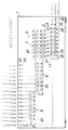
図1は、この発明の流体制御装置の第1実施形態を示している。 FIG. 1 shows a first embodiment of a fluid control apparatus of the present invention.
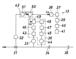
この実施形態の流体導入部(3)は、3つに分けられており、入口側に配置されてそれぞれ2×N/2個の開閉弁(23)からなる第1および第2入口側遮断開放部(5)(6)と、4×M個の開閉弁(23)からなり、第1および第2入口側遮断開放部(5)(6)と流体制御部(2)との間に配置された流体制御部側遮断開放部(7)とからなる。 The fluid introduction part (3) of this embodiment is divided into three parts, and the first and second inlet side shut-offs are arranged on the inlet side and are each composed of 2 × N / 2 open / close valves (23). Part (5) (6) and 4 × M open / close valves (23), arranged between the first and second inlet side shut-off parts (5) (6) and the fluid control part (2) The fluid control unit side cutoff opening (7).
第1および第2入口側遮断開放部(5)(6)は、N個の入口を2つの入口側遮断開放部に分けるもので、それぞれN/2個の入口と2個の出口とを有している。これにより、第1および第2入口側遮断開放部(5)(6)を合わせた出口数(流体制御部側遮断開放部(7)にとっては入口数)は、(2+2)個となり、この計4個の出口数に対応して、流体制御部側遮断開放部(7)を4×M個の開閉弁(23)によって構成することで、流体導入部(3)全体としては、M個の出口が得られ、流体導入部(3)のM個の出口と流体制御部(2)のM個の入口とが、それぞれ1:1に対応するように接続されている。 The first and second inlet-side shut-off portions (5) and (6) divide N inlets into two inlet-side shut-open portions, each having N / 2 inlets and two outlets. doing. As a result, the total number of outlets (the number of inlets for the fluid control unit side shut-off part (7)) is (2 + 2) combined with the first and second inlet side shut-off parts (5) and (6). Corresponding to the number of four outlets, the fluid control part side shut-off part (7) is constituted by 4 × M on-off valves (23), so that the fluid introduction part (3) as a whole has M pieces. An outlet is obtained, and the M outlets of the fluid introduction part (3) and the M inlets of the fluid control part (2) are connected so as to correspond to 1: 1.
図6に示したものでは、流体制御部(2)へは最大でM種類(8種類)の流体を同時に導入することができる。しかしながら、実用的には、流体制御部(2)へは最大で4種類の流体を同時に導入することができればよく、この条件下では、第1実施形態のようにすることで、開閉弁(23)の数の減少が可能となる。なお、この実施形態では、第1および第2入口側遮断開放部(5)(6)ともに出口数は2つであり、4種類の流体を同時に導入するに際しては、第1および第2入口側遮断開放部(5)(6)のいずれか一方に4種類とも導入することはできないので、第1および第2入口側遮断開放部(5)(6)にそれぞれ2種類ずつの流体が導入されることになる。 In the case shown in FIG. 6, a maximum of M types (eight types) of fluids can be simultaneously introduced into the fluid control unit (2). However, practically, it is sufficient that four types of fluids can be simultaneously introduced into the fluid control unit (2). Under this condition, the on / off valve (23 ) Can be reduced. In this embodiment, both the first and second inlet side shut-off portions (5) and (6) have two outlets, and when introducing four types of fluids simultaneously, the first and second inlet sides Since four types cannot be introduced into any one of the shut-off parts (5) and (6), two kinds of fluids are introduced into the first and second inlet-side shut-off parts (5) and (6), respectively. Will be.
こうして、第1実施形態のものによると、図6のものに比べて、開閉弁(23)の数がN×M個から(2N+4×M)個に減らされている。 Thus, according to the first embodiment, the number of on-off valves (23) is reduced from N × M to (2N + 4 × M) compared to that of FIG.
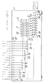
図2は、この発明の流体制御装置の第2実施形態を示している。 FIG. 2 shows a second embodiment of the fluid control apparatus of the present invention.
この実施形態の流体導入部(3)は、5つに分けられており、入口側に配置されてそれぞれN/4個の開閉弁(23)からなる第1から第4までの入口側遮断開放部(8)(9)(10)(11)と、4×M個の開閉弁(23)からなり、第1から第4までの入口側遮断開放部(8)(9)(10)(11)と流体制御部(2)との間に配置された流体制御部側遮断開放部(7)とからなる。 The fluid introduction part (3) of this embodiment is divided into five parts, and is arranged on the inlet side, and each of the first to fourth inlet side shut-offs composed of N / 4 on-off valves (23) is provided. Part (8) (9) (10) (11) and 4 × M on-off valves (23), the first to fourth inlet side shut-off parts (8) (9) (10) ( 11) and a fluid control section side shut-off section (7) disposed between the fluid control section (2).
流体制御部側遮断開放部(7)は、第1実施形態のものと同じ構成とされている。第1実施形態との相違点は、第1実施形態における第1および第2入口側遮断開放部(5)(6)がそれぞれさらに分割されて4つの入口側遮断開放部(8)(9)(10)(11)に分けられている点にある。第2実施形態のものによると、第1から第4までの各入口側遮断開放部(8)(9)(10)(11)にそれぞれ1種類ずつの流体が導入されることで、第1実施形態と同様に、第1から第4までの入口側遮断開放部(8)(9)(10)(11)の総出口数(流体制御部側遮断開放部(7)にとっては入口数)は、(1+1+1+1)の4個となり、この計4個の出口数を4×M個の開閉弁(23)からなる流体制御部側遮断開放部(7)の各入口に対応させることで、流体導入部(3)全体としては、M個の出口が得られ、流体導入部(3)のM個の出口と流体制御部(2)のM個の入口とが、それぞれ1:1に対応するように接続されている。 The fluid control unit side blocking / opening portion (7) has the same configuration as that of the first embodiment. The difference from the first embodiment is that the first and second inlet side blocking / opening portions (5) and (6) in the first embodiment are further divided into four inlet side blocking / opening portions (8) and (9). (10) The point is divided into (11). According to the second embodiment, one type of fluid is introduced into each of the first to fourth inlet-side blocking / opening portions (8), (9), (10), and (11). As in the embodiment, the total number of outlets of the first to fourth inlet side shut-off parts (8), (9), (10) and (11) (the number of inlets for the fluid control part side shut-off part (7)) Is (1 + 1 + 1 + 1), and the total number of four outlets is made to correspond to each inlet of the fluid control section side shut-off section (7) composed of 4 × M on-off valves (23). The introduction part (3) as a whole has M outlets, and the M outlets of the fluid introduction part (3) and the M inlets of the fluid control part (2) respectively correspond to 1: 1. So connected.
こうして、第2実施形態のものによると、第1実施形態のものに比べて、開閉弁(23)の数がN個さらに減らされている。 Thus, according to the second embodiment, the number of on-off valves (23) is further reduced by N as compared to the first embodiment.
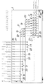
図3は、この発明の流体制御装置の第3実施形態を示している。 FIG. 3 shows a third embodiment of the fluid control apparatus of the present invention.
この実施形態の流体導入部(3)は、6つに分けられており、入口側に配置されてそれぞれN/4個の開閉弁(23)からなる第1から第4までの入口側遮断開放部(8)(9)(10)(11)と、それぞれ2×M/2個の開閉弁(23)からなり、第1から第4までの入口側遮断開放部(8)(9)(10)(11)と流体制御部(2)との間に配置された第1および第2の流体制御部側遮断開放部(12)(13)とからなる。 The fluid introduction part (3) of this embodiment is divided into six parts, and is arranged on the inlet side, and the first to fourth inlet side shut-offs each comprising N / 4 on-off valves (23) are provided. Parts (8) (9) (10) (11) and 2 × M / 2 open / close valves (23) each, and the first to fourth inlet side shut-off parts (8) (9) ( 10) It consists of the 1st and 2nd fluid control part side interruption | blocking open | release part (12) (13) arrange | positioned between (11) and the fluid control part (2).
第1から第4までの入口側遮断開放部(8)(9)(10)(11)は、第2実施形態のものと同じ構成とされている。第3実施形態の第2実施形態との相違点は、第2実施形態における流体制御部側遮断開放部(7)がそれぞれ分割されて2つの流体制御部側遮断開放部(12)(13)とされている点にある。第1および第2の流体制御部側遮断開放部(12)(13)は、全体として、入口数が4個、出口数がM個であり、これは、第2実施形態と同じである。 The first to fourth inlet-side blocking / opening portions (8), (9), (10), and (11) have the same configuration as that of the second embodiment. The difference of the third embodiment from the second embodiment is that the fluid control section side shut-off section (7) in the second embodiment is divided into two fluid control section side shut-open sections (12) (13). This is the point. The first and second fluid control unit side blocking / opening portions (12) and (13) as a whole have four inlets and M outlets, which is the same as in the second embodiment.
したがって、第3実施形態のものによると、第1から第4までの各入口側遮断開放部(8)(9)(10)(11)にそれぞれ1種類ずつの流体が導入されることで、第3実施形態と同様に、第1から第4までの入口側遮断開放部(8)(9)(10)(11)の総出口数(流体制御部側遮断開放部(12)(13)にとっては入口数)は、(1+1+1+1)の4個となり、この計4個の出口数を第1流体制御部側遮断開放部(12)の2個の入口および第2流体制御部側遮断開放部(13)の2個の入口にそれぞれ対応させることで、流体制御部側遮断開放部(12)(13)全体(流体導入部(3)全体)としては、M個の出口が得られ、流体導入部(3)のM個の出口と流体制御部(2)のM個の入口とが、それぞれ1:1に対応するように接続されている。 Therefore, according to the third embodiment, when one type of fluid is introduced into each of the first to fourth inlet side cutoff opening portions (8), (9), (10), and (11), As in the third embodiment, the total number of outlets of the first to fourth inlet side shut-off parts (8), (9), (10), and (11) (fluid control part side shut-off parts (12) and (13) The number of inlets is 4 for (1 + 1 + 1 + 1), and the total number of four outlets is the two inlets of the first fluid control unit side shut-off unit (12) and the second fluid control unit side shut-off unit. Corresponding to each of the two inlets of (13), M outlets are obtained for the fluid control unit side shut-off part (12), (13) as a whole (fluid introduction part (3) as a whole). The M outlets of the introduction part (3) and the M inlets of the fluid control part (2) are connected so as to correspond to 1: 1.
こうして、第3実施形態のものによると、第2実施形態のものに比べて、流体制御部側遮断開放部(12)(13)の開閉弁(23)の数が半分(M/2個)に減らされている。 Thus, according to the third embodiment, the number of on-off valves (23) of the fluid control section side shut-off section (12) (13) is half that of the second embodiment (M / 2). Has been reduced.
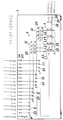
図4は、この発明の流体制御装置の第4実施形態を示している。第4実施形態のものは、第3実施形態のものと流体制御部(2)(4)の構成が相違している。 FIG. 4 shows a fourth embodiment of the fluid control apparatus of the present invention. The configuration of the fourth embodiment is different from that of the third embodiment in the configuration of the fluid control units (2) and (4).
第4実施形態のものでは、流量制御器(22)が、マスフローコントローラ(21)に代えて、圧力式のものとされている。 In the fourth embodiment, the flow rate controller (22) is a pressure type instead of the mass flow controller (21).
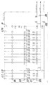
この流量制御器(21)は、図5に示すように、コントロール弁(31)、その駆動部(32)、圧力検出器(33)、オリフィス(34)、流体取出用継手(35)、流量演算回路(36)、流体種類選択回路(37)、流量設定回路(38)、比FF記憶部(39)、流量演算部(40)、流量表示部(41)および演算制御回路(42)からなる。 As shown in FIG. 5, the flow rate controller (21) includes a control valve (31), its drive unit (32), a pressure detector (33), an orifice (34), a fluid extraction joint (35), a flow rate From the calculation circuit (36), fluid type selection circuit (37), flow rate setting circuit (38), ratio FF storage unit (39), flow rate calculation unit (40), flow rate display unit (41) and calculation control circuit (42) Become.
流量演算回路(36)は、温度検出器(44)、増幅回路(43)(45)、A/D変換器(46)(47)、温度補正回路(48)および演算回路(49)からなる。また、演算制御回路(42)は比較回路(50)および増幅回路(51)からなる。 The flow rate calculation circuit (36) includes a temperature detector (44), amplification circuits (43) and (45), A / D converters (46) and (47), a temperature correction circuit (48), and a calculation circuit (49). . The arithmetic control circuit (42) includes a comparison circuit (50) and an amplifier circuit (51).
コントロール弁(31)には、所謂ダイレクトタッチ型のメタルダイヤフラム弁が使用されており、また、その駆動部(32)には圧電素子型駆動装置が使用されている。なお、これらの駆動部としてはこの他に、磁歪素子型駆動装置やソレノイド型駆動装置、モータ型駆動装置、空気圧型駆動装置、熱膨張型駆動装置が用いられる。 A so-called direct touch type metal diaphragm valve is used for the control valve (31), and a piezoelectric element type driving device is used for the driving part (32). In addition, a magnetostrictive element type drive device, a solenoid type drive device, a motor type drive device, a pneumatic type drive device, and a thermal expansion type drive device are used as these drive units.
圧力検出器(33)には半導体歪型圧力センサーが使用されているが、圧力検出器としてはこの他に、金属箔歪型圧力センサーや静電容量型圧力センサー、磁気抵抗型圧力センサー等の使用も可能である。温度検出器(44)には熱電対型温度センサーが使用されているが、測温抵抗型温度センサー等の公知の各種温度センサーが使用できる。 A semiconductor strain type pressure sensor is used for the pressure detector (33). In addition to this, as a pressure detector, a metal foil strain type pressure sensor, a capacitance type pressure sensor, a magnetoresistive type pressure sensor, etc. Use is also possible. Although a thermocouple type temperature sensor is used for the temperature detector (44), various known temperature sensors such as a resistance temperature sensor can be used.
オリフィス(34)は、所要の流量特性を具備するように、金属薄板製ガスケットに切削加工によって微小な孔を穿設して形成されている。オリフィスとしてはこの他に、エッチング及び放電加工により金属膜に孔を形成したオリフィスを使用することができる。 The orifice (34) is formed by drilling minute holes in a metal sheet gasket by cutting so as to have a required flow rate characteristic. In addition to this, an orifice in which a hole is formed in a metal film by etching and electric discharge machining can be used.
流体種類選択回路(37)は、流体を選択するもので、流量設定回路(38)はその流量設定信号Qe を演算制御回路(42)に指令する。比FF記憶部(39)はN2ガスに対する比FFを記憶したメモリーである。流量演算部(40)では比FFのデータを用いて、流通している流体種類の流量QをQ=比FF×QN(QN は相当N2ガス流量)で演算し、この値を流量表示部(41)に表示する。 The fluid type selection circuit (37) selects a fluid, and the flow rate setting circuit (38) commands the flow rate setting signal Qe to the arithmetic control circuit (42). The ratio FF storage unit (39) is a memory that stores the ratio FF for N 2 gas. The flow rate calculation unit (40) uses the data of the ratio FF to calculate the flow rate Q of the circulating fluid as Q = ratio FF × Q N (Q N is the equivalent N 2 gas flow rate), and this value is calculated as the flow rate. Displayed on the display unit (41).
この流量制御器(22)では、上流側圧力を下流側圧力の約2倍以上に保持しながら特定の流体に関し下流側の流量QcをQc=K×P(K:定数)で演算できるように設定し、この演算流量Qcと設定流量Qsとの差信号によりコントロール弁(31)が開閉制御される。 This flow rate controller (22) can calculate the downstream flow rate Qc for a specific fluid with Qc = K × P (K: constant) while maintaining the upstream pressure at about twice or more the downstream pressure. The control valve (31) is controlled to open and close by a difference signal between the calculated flow rate Qc and the set flow rate Qs.
ここで、流体種類毎にフローファクターFFは、次式で計算される。 Here, the flow factor FF for each fluid type is calculated by the following equation.
FF=(k/γ){2/(κ+1)}1/(κ−1)[κ/{(κ+1)R}1/2
γ:流体の標準状態に於ける密度、κ:流体の比熱比、R:流体定数、k:流体種類に依存しない比例定数。
FF = (k / γ) {2 / (κ + 1)} 1 / (κ−1) [κ / {(κ + 1) R} 1/2
γ: density of fluid in a standard state, κ: specific heat ratio of fluid, R: fluid constant, k: proportional constant independent of fluid type.
そして、比FF記憶部(39)に記憶された流体種類Bの流体種類Aに対する比フローファクターを使用して、流量演算部(40)において、基準となる流体種類Aの演算流量がQaの場合に、同一オリフィス、同一上流側圧力および同一上流側温度の条件下で流体種類Bを流通させたとき、その演算流量QbがQb=比フローファクター×Qaとして算出される。 Then, using the specific flow factor of the fluid type B stored in the ratio FF storage unit (39) with respect to the fluid type A, in the flow rate calculation unit (40), when the calculated flow rate of the reference fluid type A is Qa When the fluid type B is circulated under the conditions of the same orifice, the same upstream pressure, and the same upstream temperature, the calculated flow rate Qb is calculated as Qb = specific flow factor × Qa.
これにより、1台の流量制御器(22)を複数の流体種類に対応させることができ、第4実施形態のものでは、これを使用することで、第3実施形態のものに比べて、M個の流量制御器(21)をm個(例えば半分)の流量制御器(22)とすることが可能となる。減らされる流量制御器(22)の数は、流体の種類や流量範囲によって適宜変更される。 Thereby, one flow controller (22) can be made to correspond to a plurality of fluid types, and in the fourth embodiment, by using this, M can be compared with that in the third embodiment. The number of flow rate controllers (21) can be set to m (for example, half) flow rate controllers (22). The number of flow controllers (22) to be reduced is appropriately changed according to the type of fluid and the flow range.
この第4実施形態の流体制御部(4)は、第1から第3までの実施形態の流体制御装置(1)にも適用可能であり、これにより、各実施形態から流量制御器(21)の数を減らすことができる。 The fluid control unit (4) of the fourth embodiment can also be applied to the fluid control device (1) of the first to third embodiments, whereby the flow rate controller (21) is changed from each embodiment. The number of can be reduced.
(1) 流体制御装置
(2)(4) 流体制御部
(3) 流体導入部
(5)(6) 第1および第2入口側遮断開放部
(7) 流体制御部側遮断開放部
(8)(9)(10)(11)第1〜第4入口側遮断開放部
(12)(13) 第1および第2流体制御部側遮断開放部
(21)(22) 流量制御器
(23) 開閉弁
(31) コントロール弁
(32) 駆動部
(33) 圧力検出器
(34) オリフィス
(42) 演算制御回路(演算制御装置)
L1〜L8 流体制御ライン
(1) Fluid control device
(2) (4) Fluid control unit
(3) Fluid introduction part
(5) (6) First and second inlet side shut-off parts
(7) Fluid control part side shut-off part
(8) (9) (10) (11) 1st to 4th inlet side shut-off part
(12) (13) First and second fluid control part side shut-off part
(21) (22) Flow controller
(23) On-off valve
(31) Control valve
(32) Drive unit
(33) Pressure detector
(34) Orifice
(42) Arithmetic control circuit (arithmetic control device)
L1-L8 Fluid control line
Claims (5)
流体導入部は、複数の開閉弁からなり入口側に配置されて入口の総数がN個で出口の総数がK個である入口側遮断開放部と、複数の開閉弁からなり入口側遮断開放部と流体制御部との間に配置されて入口の総数がK個で出口の総数がM個である流体制御部側遮断開放部とに分けられるとともに、入口側遮断開放部は、それぞれ2以上の所要数の開閉弁を有する複数のグループに分けられていることを特徴とする流体制御装置。 A fluid control unit in which M rows of fluid control lines each having one inlet and one outlet each having a single flow rate controller as a basic component and a plurality of on-off valves are used, and the number of inlets is N (> M). In the fluid control apparatus, the number of the fluid introduction units configured to be M, and the M outlets of the fluid introduction unit and the M inlets of the fluid control unit are respectively connected by 1: 1. ,
The fluid introduction part is composed of a plurality of on-off valves and is arranged on the inlet side. The inlet-side shut-off part has a total number of inlets of N and the total number of outlets is K, and the inlet-side shut-off part of the plurality of on-off valves. And the fluid control unit, the total number of inlets is K, and the total number of outlets is M. The fluid control unit side cutoff / opening unit is divided into two or more. A fluid control device, wherein the fluid control device is divided into a plurality of groups having a required number of on-off valves.
Priority Applications (6)
| Application Number | Priority Date | Filing Date | Title |
|---|---|---|---|
| JP2009049045A JP5216632B2 (en) | 2009-03-03 | 2009-03-03 | Fluid control device |
| PCT/JP2009/068982 WO2010100792A1 (en) | 2009-03-03 | 2009-11-06 | Fluid controller |
| KR1020117020923A KR101661003B1 (en) | 2009-03-03 | 2009-11-06 | Fluid controller |
| CN200980157836XA CN102341760B (en) | 2009-03-03 | 2009-11-06 | fluid control device |
| US13/203,866 US9169558B2 (en) | 2009-03-03 | 2009-11-06 | Fluid control apparatus |
| TW099105894A TWI483089B (en) | 2009-03-03 | 2010-03-02 | Fluid control device |
Applications Claiming Priority (1)
| Application Number | Priority Date | Filing Date | Title |
|---|---|---|---|
| JP2009049045A JP5216632B2 (en) | 2009-03-03 | 2009-03-03 | Fluid control device |
Publications (2)
| Publication Number | Publication Date |
|---|---|
| JP2010204899A JP2010204899A (en) | 2010-09-16 |
| JP5216632B2 true JP5216632B2 (en) | 2013-06-19 |
Family
ID=42709367
Family Applications (1)
| Application Number | Title | Priority Date | Filing Date |
|---|---|---|---|
| JP2009049045A Active JP5216632B2 (en) | 2009-03-03 | 2009-03-03 | Fluid control device |
Country Status (6)
| Country | Link |
|---|---|
| US (1) | US9169558B2 (en) |
| JP (1) | JP5216632B2 (en) |
| KR (1) | KR101661003B1 (en) |
| CN (1) | CN102341760B (en) |
| TW (1) | TWI483089B (en) |
| WO (1) | WO2010100792A1 (en) |
Families Citing this family (328)
| Publication number | Priority date | Publication date | Assignee | Title |
|---|---|---|---|---|
| US9394608B2 (en) | 2009-04-06 | 2016-07-19 | Asm America, Inc. | Semiconductor processing reactor and components thereof |
| US8802201B2 (en) | 2009-08-14 | 2014-08-12 | Asm America, Inc. | Systems and methods for thin-film deposition of metal oxides using excited nitrogen-oxygen species |
| JP5562712B2 (en) * | 2010-04-30 | 2014-07-30 | 東京エレクトロン株式会社 | Gas supply equipment for semiconductor manufacturing equipment |
| US20130023129A1 (en) | 2011-07-20 | 2013-01-24 | Asm America, Inc. | Pressure transmitter for a semiconductor processing environment |
| KR101940325B1 (en) | 2011-10-05 | 2019-01-18 | 가부시키가이샤 호리바 에스텍 | Fluid mechanism, support member constituting fluid mechanism and fluid control system |
| JP5803552B2 (en) * | 2011-10-14 | 2015-11-04 | 東京エレクトロン株式会社 | Processing equipment |
| US9017481B1 (en) | 2011-10-28 | 2015-04-28 | Asm America, Inc. | Process feed management for semiconductor substrate processing |
| TW201335725A (en) * | 2012-02-16 | 2013-09-01 | jun-xian Li | Safety protection device and its control method |
| US10714315B2 (en) | 2012-10-12 | 2020-07-14 | Asm Ip Holdings B.V. | Semiconductor reaction chamber showerhead |
| US20160376700A1 (en) | 2013-02-01 | 2016-12-29 | Asm Ip Holding B.V. | System for treatment of deposition reactor |
| US9454158B2 (en) | 2013-03-15 | 2016-09-27 | Bhushan Somani | Real time diagnostics for flow controller systems and methods |
| US11015245B2 (en) | 2014-03-19 | 2021-05-25 | Asm Ip Holding B.V. | Gas-phase reactor and system having exhaust plenum and components thereof |
| US10858737B2 (en) | 2014-07-28 | 2020-12-08 | Asm Ip Holding B.V. | Showerhead assembly and components thereof |
| JP6346849B2 (en) | 2014-08-20 | 2018-06-20 | 東京エレクトロン株式会社 | Gas supply system, plasma processing apparatus, and operation method of plasma processing apparatus |
| US9890456B2 (en) | 2014-08-21 | 2018-02-13 | Asm Ip Holding B.V. | Method and system for in situ formation of gas-phase compounds |
| US10941490B2 (en) | 2014-10-07 | 2021-03-09 | Asm Ip Holding B.V. | Multiple temperature range susceptor, assembly, reactor and system including the susceptor, and methods of using the same |
| US10658222B2 (en) | 2015-01-16 | 2020-05-19 | Lam Research Corporation | Moveable edge coupling ring for edge process control during semiconductor wafer processing |
| US10276355B2 (en) | 2015-03-12 | 2019-04-30 | Asm Ip Holding B.V. | Multi-zone reactor, system including the reactor, and method of using the same |
| US10458018B2 (en) | 2015-06-26 | 2019-10-29 | Asm Ip Holding B.V. | Structures including metal carbide material, devices including the structures, and methods of forming same |
| US10957561B2 (en) * | 2015-07-30 | 2021-03-23 | Lam Research Corporation | Gas delivery system |
| US10192751B2 (en) | 2015-10-15 | 2019-01-29 | Lam Research Corporation | Systems and methods for ultrahigh selective nitride etch |
| US10211308B2 (en) | 2015-10-21 | 2019-02-19 | Asm Ip Holding B.V. | NbMC layers |
| US11139308B2 (en) | 2015-12-29 | 2021-10-05 | Asm Ip Holding B.V. | Atomic layer deposition of III-V compounds to form V-NAND devices |
| US10825659B2 (en) | 2016-01-07 | 2020-11-03 | Lam Research Corporation | Substrate processing chamber including multiple gas injection points and dual injector |
| US10147588B2 (en) | 2016-02-12 | 2018-12-04 | Lam Research Corporation | System and method for increasing electron density levels in a plasma of a substrate processing system |
| US10699878B2 (en) | 2016-02-12 | 2020-06-30 | Lam Research Corporation | Chamber member of a plasma source and pedestal with radially outward positioned lift pins for translation of a substrate c-ring |
| US10651015B2 (en) | 2016-02-12 | 2020-05-12 | Lam Research Corporation | Variable depth edge ring for etch uniformity control |
| US10438833B2 (en) | 2016-02-16 | 2019-10-08 | Lam Research Corporation | Wafer lift ring system for wafer transfer |
| US10529554B2 (en) | 2016-02-19 | 2020-01-07 | Asm Ip Holding B.V. | Method for forming silicon nitride film selectively on sidewalls or flat surfaces of trenches |
| JP6573559B2 (en) * | 2016-03-03 | 2019-09-11 | 東京エレクトロン株式会社 | Vaporizing raw material supply apparatus and substrate processing apparatus using the same |
| US10343920B2 (en) | 2016-03-18 | 2019-07-09 | Asm Ip Holding B.V. | Aligned carbon nanotubes |
| US10190213B2 (en) | 2016-04-21 | 2019-01-29 | Asm Ip Holding B.V. | Deposition of metal borides |
| US10865475B2 (en) | 2016-04-21 | 2020-12-15 | Asm Ip Holding B.V. | Deposition of metal borides and silicides |
| US10367080B2 (en) | 2016-05-02 | 2019-07-30 | Asm Ip Holding B.V. | Method of forming a germanium oxynitride film |
| US11453943B2 (en) | 2016-05-25 | 2022-09-27 | Asm Ip Holding B.V. | Method for forming carbon-containing silicon/metal oxide or nitride film by ALD using silicon precursor and hydrocarbon precursor |
| US10612137B2 (en) | 2016-07-08 | 2020-04-07 | Asm Ip Holdings B.V. | Organic reactants for atomic layer deposition |
| US9859151B1 (en) | 2016-07-08 | 2018-01-02 | Asm Ip Holding B.V. | Selective film deposition method to form air gaps |
| US9887082B1 (en) | 2016-07-28 | 2018-02-06 | Asm Ip Holding B.V. | Method and apparatus for filling a gap |
| KR102532607B1 (en) | 2016-07-28 | 2023-05-15 | 에이에스엠 아이피 홀딩 비.브이. | Substrate processing apparatus and method of operating the same |
| US9812320B1 (en) | 2016-07-28 | 2017-11-07 | Asm Ip Holding B.V. | Method and apparatus for filling a gap |
| US10410832B2 (en) | 2016-08-19 | 2019-09-10 | Lam Research Corporation | Control of on-wafer CD uniformity with movable edge ring and gas injection adjustment |
| US10643826B2 (en) | 2016-10-26 | 2020-05-05 | Asm Ip Holdings B.V. | Methods for thermally calibrating reaction chambers |
| US11532757B2 (en) | 2016-10-27 | 2022-12-20 | Asm Ip Holding B.V. | Deposition of charge trapping layers |
| US10714350B2 (en) | 2016-11-01 | 2020-07-14 | ASM IP Holdings, B.V. | Methods for forming a transition metal niobium nitride film on a substrate by atomic layer deposition and related semiconductor device structures |
| US10229833B2 (en) | 2016-11-01 | 2019-03-12 | Asm Ip Holding B.V. | Methods for forming a transition metal nitride film on a substrate by atomic layer deposition and related semiconductor device structures |
| KR102546317B1 (en) | 2016-11-15 | 2023-06-21 | 에이에스엠 아이피 홀딩 비.브이. | Gas supply unit and substrate processing apparatus including the same |
| KR102762543B1 (en) | 2016-12-14 | 2025-02-05 | 에이에스엠 아이피 홀딩 비.브이. | Substrate processing apparatus |
| US11447861B2 (en) | 2016-12-15 | 2022-09-20 | Asm Ip Holding B.V. | Sequential infiltration synthesis apparatus and a method of forming a patterned structure |
| US11581186B2 (en) | 2016-12-15 | 2023-02-14 | Asm Ip Holding B.V. | Sequential infiltration synthesis apparatus |
| KR102700194B1 (en) | 2016-12-19 | 2024-08-28 | 에이에스엠 아이피 홀딩 비.브이. | Substrate processing apparatus |
| US10269558B2 (en) | 2016-12-22 | 2019-04-23 | Asm Ip Holding B.V. | Method of forming a structure on a substrate |
| US10867788B2 (en) | 2016-12-28 | 2020-12-15 | Asm Ip Holding B.V. | Method of forming a structure on a substrate |
| US11390950B2 (en) | 2017-01-10 | 2022-07-19 | Asm Ip Holding B.V. | Reactor system and method to reduce residue buildup during a film deposition process |
| US10468261B2 (en) | 2017-02-15 | 2019-11-05 | Asm Ip Holding B.V. | Methods for forming a metallic film on a substrate by cyclical deposition and related semiconductor device structures |
| US10983537B2 (en) | 2017-02-27 | 2021-04-20 | Flow Devices And Systems Inc. | Systems and methods for flow sensor back pressure adjustment for mass flow controller |
| US10529563B2 (en) | 2017-03-29 | 2020-01-07 | Asm Ip Holdings B.V. | Method for forming doped metal oxide films on a substrate by cyclical deposition and related semiconductor device structures |
| KR102457289B1 (en) | 2017-04-25 | 2022-10-21 | 에이에스엠 아이피 홀딩 비.브이. | Method for depositing a thin film and manufacturing a semiconductor device |
| US10770286B2 (en) | 2017-05-08 | 2020-09-08 | Asm Ip Holdings B.V. | Methods for selectively forming a silicon nitride film on a substrate and related semiconductor device structures |
| US10892156B2 (en) | 2017-05-08 | 2021-01-12 | Asm Ip Holding B.V. | Methods for forming a silicon nitride film on a substrate and related semiconductor device structures |
| US10886123B2 (en) | 2017-06-02 | 2021-01-05 | Asm Ip Holding B.V. | Methods for forming low temperature semiconductor layers and related semiconductor device structures |
| US12040200B2 (en) | 2017-06-20 | 2024-07-16 | Asm Ip Holding B.V. | Semiconductor processing apparatus and methods for calibrating a semiconductor processing apparatus |
| US11306395B2 (en) | 2017-06-28 | 2022-04-19 | Asm Ip Holding B.V. | Methods for depositing a transition metal nitride film on a substrate by atomic layer deposition and related deposition apparatus |
| KR20190009245A (en) | 2017-07-18 | 2019-01-28 | 에이에스엠 아이피 홀딩 비.브이. | Methods for forming a semiconductor device structure and related semiconductor device structures |
| US10541333B2 (en) | 2017-07-19 | 2020-01-21 | Asm Ip Holding B.V. | Method for depositing a group IV semiconductor and related semiconductor device structures |
| US11374112B2 (en) | 2017-07-19 | 2022-06-28 | Asm Ip Holding B.V. | Method for depositing a group IV semiconductor and related semiconductor device structures |
| US11018002B2 (en) | 2017-07-19 | 2021-05-25 | Asm Ip Holding B.V. | Method for selectively depositing a Group IV semiconductor and related semiconductor device structures |
| US10590535B2 (en) | 2017-07-26 | 2020-03-17 | Asm Ip Holdings B.V. | Chemical treatment, deposition and/or infiltration apparatus and method for using the same |
| TWI815813B (en) | 2017-08-04 | 2023-09-21 | 荷蘭商Asm智慧財產控股公司 | Showerhead assembly for distributing a gas within a reaction chamber |
| US10770336B2 (en) | 2017-08-08 | 2020-09-08 | Asm Ip Holding B.V. | Substrate lift mechanism and reactor including same |
| US10692741B2 (en) | 2017-08-08 | 2020-06-23 | Asm Ip Holdings B.V. | Radiation shield |
| US11769682B2 (en) | 2017-08-09 | 2023-09-26 | Asm Ip Holding B.V. | Storage apparatus for storing cassettes for substrates and processing apparatus equipped therewith |
| US11139191B2 (en) | 2017-08-09 | 2021-10-05 | Asm Ip Holding B.V. | Storage apparatus for storing cassettes for substrates and processing apparatus equipped therewith |
| US11830730B2 (en) | 2017-08-29 | 2023-11-28 | Asm Ip Holding B.V. | Layer forming method and apparatus |
| US11056344B2 (en) | 2017-08-30 | 2021-07-06 | Asm Ip Holding B.V. | Layer forming method |
| US11295980B2 (en) | 2017-08-30 | 2022-04-05 | Asm Ip Holding B.V. | Methods for depositing a molybdenum metal film over a dielectric surface of a substrate by a cyclical deposition process and related semiconductor device structures |
| KR102491945B1 (en) | 2017-08-30 | 2023-01-26 | 에이에스엠 아이피 홀딩 비.브이. | Substrate processing apparatus |
| KR102401446B1 (en) | 2017-08-31 | 2022-05-24 | 에이에스엠 아이피 홀딩 비.브이. | Substrate processing apparatus |
| KR102630301B1 (en) | 2017-09-21 | 2024-01-29 | 에이에스엠 아이피 홀딩 비.브이. | Method of sequential infiltration synthesis treatment of infiltrateable material and structures and devices formed using same |
| US10844484B2 (en) | 2017-09-22 | 2020-11-24 | Asm Ip Holding B.V. | Apparatus for dispensing a vapor phase reactant to a reaction chamber and related methods |
| US10658205B2 (en) | 2017-09-28 | 2020-05-19 | Asm Ip Holdings B.V. | Chemical dispensing apparatus and methods for dispensing a chemical to a reaction chamber |
| US10403504B2 (en) | 2017-10-05 | 2019-09-03 | Asm Ip Holding B.V. | Method for selectively depositing a metallic film on a substrate |
| US10923344B2 (en) | 2017-10-30 | 2021-02-16 | Asm Ip Holding B.V. | Methods for forming a semiconductor structure and related semiconductor structures |
| US20190073238A1 (en) * | 2017-11-02 | 2019-03-07 | Nri R&D Patent Licensing, Llc | Software controlled transport and operation processes for fluidic and microfluidic systems, temporal and event-driven control sequence scripting, functional libraries, and script creation tools |
| US10910262B2 (en) | 2017-11-16 | 2021-02-02 | Asm Ip Holding B.V. | Method of selectively depositing a capping layer structure on a semiconductor device structure |
| WO2019103722A1 (en) | 2017-11-21 | 2019-05-31 | Lam Research Corporation | Bottom and middle edge rings |
| US11022879B2 (en) | 2017-11-24 | 2021-06-01 | Asm Ip Holding B.V. | Method of forming an enhanced unexposed photoresist layer |
| TWI791689B (en) | 2017-11-27 | 2023-02-11 | 荷蘭商Asm智慧財產控股私人有限公司 | Apparatus including a clean mini environment |
| JP7214724B2 (en) | 2017-11-27 | 2023-01-30 | エーエスエム アイピー ホールディング ビー.ブイ. | Storage device for storing wafer cassettes used in batch furnaces |
| US10872771B2 (en) | 2018-01-16 | 2020-12-22 | Asm Ip Holding B. V. | Method for depositing a material film on a substrate within a reaction chamber by a cyclical deposition process and related device structures |
| KR102695659B1 (en) | 2018-01-19 | 2024-08-14 | 에이에스엠 아이피 홀딩 비.브이. | Method for depositing a gap filling layer by plasma assisted deposition |
| TWI799494B (en) | 2018-01-19 | 2023-04-21 | 荷蘭商Asm 智慧財產控股公司 | Deposition method |
| US11018047B2 (en) | 2018-01-25 | 2021-05-25 | Asm Ip Holding B.V. | Hybrid lift pin |
| USD880437S1 (en) | 2018-02-01 | 2020-04-07 | Asm Ip Holding B.V. | Gas supply plate for semiconductor manufacturing apparatus |
| US11081345B2 (en) | 2018-02-06 | 2021-08-03 | Asm Ip Holding B.V. | Method of post-deposition treatment for silicon oxide film |
| US10896820B2 (en) | 2018-02-14 | 2021-01-19 | Asm Ip Holding B.V. | Method for depositing a ruthenium-containing film on a substrate by a cyclical deposition process |
| US11685991B2 (en) | 2018-02-14 | 2023-06-27 | Asm Ip Holding B.V. | Method for depositing a ruthenium-containing film on a substrate by a cyclical deposition process |
| US10731249B2 (en) | 2018-02-15 | 2020-08-04 | Asm Ip Holding B.V. | Method of forming a transition metal containing film on a substrate by a cyclical deposition process, a method for supplying a transition metal halide compound to a reaction chamber, and related vapor deposition apparatus |
| KR102636427B1 (en) | 2018-02-20 | 2024-02-13 | 에이에스엠 아이피 홀딩 비.브이. | Substrate processing method and apparatus |
| US10975470B2 (en) | 2018-02-23 | 2021-04-13 | Asm Ip Holding B.V. | Apparatus for detecting or monitoring for a chemical precursor in a high temperature environment |
| US11473195B2 (en) | 2018-03-01 | 2022-10-18 | Asm Ip Holding B.V. | Semiconductor processing apparatus and a method for processing a substrate |
| US11629406B2 (en) | 2018-03-09 | 2023-04-18 | Asm Ip Holding B.V. | Semiconductor processing apparatus comprising one or more pyrometers for measuring a temperature of a substrate during transfer of the substrate |
| US11114283B2 (en) | 2018-03-16 | 2021-09-07 | Asm Ip Holding B.V. | Reactor, system including the reactor, and methods of manufacturing and using same |
| KR102646467B1 (en) | 2018-03-27 | 2024-03-11 | 에이에스엠 아이피 홀딩 비.브이. | Method of forming an electrode on a substrate and a semiconductor device structure including an electrode |
| US11088002B2 (en) | 2018-03-29 | 2021-08-10 | Asm Ip Holding B.V. | Substrate rack and a substrate processing system and method |
| US11230766B2 (en) | 2018-03-29 | 2022-01-25 | Asm Ip Holding B.V. | Substrate processing apparatus and method |
| KR102501472B1 (en) | 2018-03-30 | 2023-02-20 | 에이에스엠 아이피 홀딩 비.브이. | Substrate processing method |
| KR102600229B1 (en) | 2018-04-09 | 2023-11-10 | 에이에스엠 아이피 홀딩 비.브이. | Substrate supporting device, substrate processing apparatus including the same and substrate processing method |
| TWI843623B (en) | 2018-05-08 | 2024-05-21 | 荷蘭商Asm Ip私人控股有限公司 | Methods for depositing an oxide film on a substrate by a cyclical deposition process and related device structures |
| US12025484B2 (en) | 2018-05-08 | 2024-07-02 | Asm Ip Holding B.V. | Thin film forming method |
| US12272527B2 (en) | 2018-05-09 | 2025-04-08 | Asm Ip Holding B.V. | Apparatus for use with hydrogen radicals and method of using same |
| KR20190129718A (en) | 2018-05-11 | 2019-11-20 | 에이에스엠 아이피 홀딩 비.브이. | Methods for forming a doped metal carbide film on a substrate and related semiconductor device structures |
| KR102596988B1 (en) | 2018-05-28 | 2023-10-31 | 에이에스엠 아이피 홀딩 비.브이. | Method of processing a substrate and a device manufactured by the same |
| TWI840362B (en) | 2018-06-04 | 2024-05-01 | 荷蘭商Asm Ip私人控股有限公司 | Wafer handling chamber with moisture reduction |
| US11718913B2 (en) * | 2018-06-04 | 2023-08-08 | Asm Ip Holding B.V. | Gas distribution system and reactor system including same |
| US11286562B2 (en) | 2018-06-08 | 2022-03-29 | Asm Ip Holding B.V. | Gas-phase chemical reactor and method of using same |
| KR102568797B1 (en) | 2018-06-21 | 2023-08-21 | 에이에스엠 아이피 홀딩 비.브이. | Substrate processing system |
| US10797133B2 (en) | 2018-06-21 | 2020-10-06 | Asm Ip Holding B.V. | Method for depositing a phosphorus doped silicon arsenide film and related semiconductor device structures |
| US11499222B2 (en) | 2018-06-27 | 2022-11-15 | Asm Ip Holding B.V. | Cyclic deposition methods for forming metal-containing material and films and structures including the metal-containing material |
| TWI871083B (en) | 2018-06-27 | 2025-01-21 | 荷蘭商Asm Ip私人控股有限公司 | Cyclic deposition processes for forming metal-containing material |
| US10612136B2 (en) | 2018-06-29 | 2020-04-07 | ASM IP Holding, B.V. | Temperature-controlled flange and reactor system including same |
| KR102686758B1 (en) | 2018-06-29 | 2024-07-18 | 에이에스엠 아이피 홀딩 비.브이. | Method for depositing a thin film and manufacturing a semiconductor device |
| JP7296699B2 (en) * | 2018-07-02 | 2023-06-23 | 東京エレクトロン株式会社 | GAS SUPPLY SYSTEM, PLASMA PROCESSING APPARATUS, AND GAS SUPPLY SYSTEM CONTROL METHOD |
| US10388513B1 (en) | 2018-07-03 | 2019-08-20 | Asm Ip Holding B.V. | Method for depositing silicon-free carbon-containing film as gap-fill layer by pulse plasma-assisted deposition |
| US10755922B2 (en) | 2018-07-03 | 2020-08-25 | Asm Ip Holding B.V. | Method for depositing silicon-free carbon-containing film as gap-fill layer by pulse plasma-assisted deposition |
| US10767789B2 (en) | 2018-07-16 | 2020-09-08 | Asm Ip Holding B.V. | Diaphragm valves, valve components, and methods for forming valve components |
| US11053591B2 (en) | 2018-08-06 | 2021-07-06 | Asm Ip Holding B.V. | Multi-port gas injection system and reactor system including same |
| US10883175B2 (en) | 2018-08-09 | 2021-01-05 | Asm Ip Holding B.V. | Vertical furnace for processing substrates and a liner for use therein |
| CN118398464A (en) | 2018-08-13 | 2024-07-26 | 朗姆研究公司 | Replaceable and/or collapsible edge ring assembly incorporating edge ring positioning and centering functions for plasma sheath adjustment |
| US10829852B2 (en) | 2018-08-16 | 2020-11-10 | Asm Ip Holding B.V. | Gas distribution device for a wafer processing apparatus |
| US11430674B2 (en) | 2018-08-22 | 2022-08-30 | Asm Ip Holding B.V. | Sensor array, apparatus for dispensing a vapor phase reactant to a reaction chamber and related methods |
| US11024523B2 (en) | 2018-09-11 | 2021-06-01 | Asm Ip Holding B.V. | Substrate processing apparatus and method |
| KR102707956B1 (en) | 2018-09-11 | 2024-09-19 | 에이에스엠 아이피 홀딩 비.브이. | Method for deposition of a thin film |
| US11049751B2 (en) | 2018-09-14 | 2021-06-29 | Asm Ip Holding B.V. | Cassette supply system to store and handle cassettes and processing apparatus equipped therewith |
| CN110970344B (en) | 2018-10-01 | 2024-10-25 | Asmip控股有限公司 | Substrate holding device, system including the same and method of using the same |
| US11232963B2 (en) | 2018-10-03 | 2022-01-25 | Asm Ip Holding B.V. | Substrate processing apparatus and method |
| KR102592699B1 (en) | 2018-10-08 | 2023-10-23 | 에이에스엠 아이피 홀딩 비.브이. | Substrate support unit and apparatuses for depositing thin film and processing the substrate including the same |
| KR102546322B1 (en) | 2018-10-19 | 2023-06-21 | 에이에스엠 아이피 홀딩 비.브이. | Substrate processing apparatus and substrate processing method |
| KR102605121B1 (en) | 2018-10-19 | 2023-11-23 | 에이에스엠 아이피 홀딩 비.브이. | Substrate processing apparatus and substrate processing method |
| USD948463S1 (en) | 2018-10-24 | 2022-04-12 | Asm Ip Holding B.V. | Susceptor for semiconductor substrate supporting apparatus |
| US12378665B2 (en) | 2018-10-26 | 2025-08-05 | Asm Ip Holding B.V. | High temperature coatings for a preclean and etch apparatus and related methods |
| US11087997B2 (en) | 2018-10-31 | 2021-08-10 | Asm Ip Holding B.V. | Substrate processing apparatus for processing substrates |
| KR102748291B1 (en) | 2018-11-02 | 2024-12-31 | 에이에스엠 아이피 홀딩 비.브이. | Substrate support unit and substrate processing apparatus including the same |
| US11572620B2 (en) | 2018-11-06 | 2023-02-07 | Asm Ip Holding B.V. | Methods for selectively depositing an amorphous silicon film on a substrate |
| US11031242B2 (en) | 2018-11-07 | 2021-06-08 | Asm Ip Holding B.V. | Methods for depositing a boron doped silicon germanium film |
| US10818758B2 (en) | 2018-11-16 | 2020-10-27 | Asm Ip Holding B.V. | Methods for forming a metal silicate film on a substrate in a reaction chamber and related semiconductor device structures |
| US10847366B2 (en) | 2018-11-16 | 2020-11-24 | Asm Ip Holding B.V. | Methods for depositing a transition metal chalcogenide film on a substrate by a cyclical deposition process |
| US12040199B2 (en) | 2018-11-28 | 2024-07-16 | Asm Ip Holding B.V. | Substrate processing apparatus for processing substrates |
| US11217444B2 (en) | 2018-11-30 | 2022-01-04 | Asm Ip Holding B.V. | Method for forming an ultraviolet radiation responsive metal oxide-containing film |
| KR102636428B1 (en) | 2018-12-04 | 2024-02-13 | 에이에스엠 아이피 홀딩 비.브이. | A method for cleaning a substrate processing apparatus |
| US11158513B2 (en) | 2018-12-13 | 2021-10-26 | Asm Ip Holding B.V. | Methods for forming a rhenium-containing film on a substrate by a cyclical deposition process and related semiconductor device structures |
| JP7504584B2 (en) | 2018-12-14 | 2024-06-24 | エーエスエム・アイピー・ホールディング・ベー・フェー | Method and system for forming device structures using selective deposition of gallium nitride - Patents.com |
| TWI866480B (en) | 2019-01-17 | 2024-12-11 | 荷蘭商Asm Ip 私人控股有限公司 | Methods of forming a transition metal containing film on a substrate by a cyclical deposition process |
| KR102727227B1 (en) | 2019-01-22 | 2024-11-07 | 에이에스엠 아이피 홀딩 비.브이. | Semiconductor processing device |
| CN111524788B (en) | 2019-02-01 | 2023-11-24 | Asm Ip私人控股有限公司 | Method for forming topologically selective films of silicon oxide |
| TWI873122B (en) | 2019-02-20 | 2025-02-21 | 荷蘭商Asm Ip私人控股有限公司 | Method of filling a recess formed within a surface of a substrate, semiconductor structure formed according to the method, and semiconductor processing apparatus |
| KR102626263B1 (en) | 2019-02-20 | 2024-01-16 | 에이에스엠 아이피 홀딩 비.브이. | Cyclical deposition method including treatment step and apparatus for same |
| KR20200102357A (en) | 2019-02-20 | 2020-08-31 | 에이에스엠 아이피 홀딩 비.브이. | Apparatus and methods for plug fill deposition in 3-d nand applications |
| TWI845607B (en) | 2019-02-20 | 2024-06-21 | 荷蘭商Asm Ip私人控股有限公司 | Cyclical deposition method and apparatus for filling a recess formed within a substrate surface |
| TWI842826B (en) | 2019-02-22 | 2024-05-21 | 荷蘭商Asm Ip私人控股有限公司 | Substrate processing apparatus and method for processing substrate |
| KR102782593B1 (en) | 2019-03-08 | 2025-03-14 | 에이에스엠 아이피 홀딩 비.브이. | Structure Including SiOC Layer and Method of Forming Same |
| KR102858005B1 (en) | 2019-03-08 | 2025-09-09 | 에이에스엠 아이피 홀딩 비.브이. | Method for Selective Deposition of Silicon Nitride Layer and Structure Including Selectively-Deposited Silicon Nitride Layer |
| KR102762833B1 (en) | 2019-03-08 | 2025-02-04 | 에이에스엠 아이피 홀딩 비.브이. | STRUCTURE INCLUDING SiOCN LAYER AND METHOD OF FORMING SAME |
| JP2020167398A (en) | 2019-03-28 | 2020-10-08 | エーエスエム・アイピー・ホールディング・ベー・フェー | Door openers and substrate processing equipment provided with door openers |
| KR102809999B1 (en) | 2019-04-01 | 2025-05-19 | 에이에스엠 아이피 홀딩 비.브이. | Method of manufacturing semiconductor device |
| KR102897355B1 (en) | 2019-04-19 | 2025-12-08 | 에이에스엠 아이피 홀딩 비.브이. | Layer forming method and apparatus |
| KR20200125453A (en) | 2019-04-24 | 2020-11-04 | 에이에스엠 아이피 홀딩 비.브이. | Gas-phase reactor system and method of using same |
| US12259739B2 (en) * | 2019-04-30 | 2025-03-25 | Illinois Tool Works Inc. | Advanced pressure based mass flow controllers and diagnostics |
| KR102869364B1 (en) | 2019-05-07 | 2025-10-10 | 에이에스엠 아이피 홀딩 비.브이. | Method for Reforming Amorphous Carbon Polymer Film |
| KR102929471B1 (en) | 2019-05-07 | 2026-02-20 | 에이에스엠 아이피 홀딩 비.브이. | Chemical source vessel with dip tube |
| KR102929472B1 (en) | 2019-05-10 | 2026-02-20 | 에이에스엠 아이피 홀딩 비.브이. | Method of depositing material onto a surface and structure formed according to the method |
| JP7612342B2 (en) | 2019-05-16 | 2025-01-14 | エーエスエム・アイピー・ホールディング・ベー・フェー | Wafer boat handling apparatus, vertical batch furnace and method |
| JP7598201B2 (en) | 2019-05-16 | 2024-12-11 | エーエスエム・アイピー・ホールディング・ベー・フェー | Wafer boat handling apparatus, vertical batch furnace and method |
| USD947913S1 (en) | 2019-05-17 | 2022-04-05 | Asm Ip Holding B.V. | Susceptor shaft |
| USD975665S1 (en) | 2019-05-17 | 2023-01-17 | Asm Ip Holding B.V. | Susceptor shaft |
| USD935572S1 (en) | 2019-05-24 | 2021-11-09 | Asm Ip Holding B.V. | Gas channel plate |
| USD922229S1 (en) | 2019-06-05 | 2021-06-15 | Asm Ip Holding B.V. | Device for controlling a temperature of a gas supply unit |
| KR20200141002A (en) | 2019-06-06 | 2020-12-17 | 에이에스엠 아이피 홀딩 비.브이. | Method of using a gas-phase reactor system including analyzing exhausted gas |
| KR102918757B1 (en) | 2019-06-10 | 2026-01-28 | 에이에스엠 아이피 홀딩 비.브이. | Method for cleaning quartz epitaxial chambers |
| KR20200143254A (en) | 2019-06-11 | 2020-12-23 | 에이에스엠 아이피 홀딩 비.브이. | Method of forming an electronic structure using an reforming gas, system for performing the method, and structure formed using the method |
| USD944946S1 (en) | 2019-06-14 | 2022-03-01 | Asm Ip Holding B.V. | Shower plate |
| USD931978S1 (en) | 2019-06-27 | 2021-09-28 | Asm Ip Holding B.V. | Showerhead vacuum transport |
| KR102911421B1 (en) | 2019-07-03 | 2026-01-12 | 에이에스엠 아이피 홀딩 비.브이. | Temperature control assembly for substrate processing apparatus and method of using same |
| JP7499079B2 (en) | 2019-07-09 | 2024-06-13 | エーエスエム・アイピー・ホールディング・ベー・フェー | Plasma device using coaxial waveguide and substrate processing method |
| CN112216646B (en) | 2019-07-10 | 2026-02-10 | Asmip私人控股有限公司 | Substrate support assembly and substrate processing apparatus including the thereof |
| KR102895115B1 (en) | 2019-07-16 | 2025-12-03 | 에이에스엠 아이피 홀딩 비.브이. | Substrate processing apparatus |
| KR102860110B1 (en) | 2019-07-17 | 2025-09-16 | 에이에스엠 아이피 홀딩 비.브이. | Methods of forming silicon germanium structures |
| TWI826704B (en) | 2019-07-17 | 2023-12-21 | 荷蘭商Asm Ip私人控股有限公司 | Radical assist ignition plasma system and method |
| US11643724B2 (en) | 2019-07-18 | 2023-05-09 | Asm Ip Holding B.V. | Method of forming structures using a neutral beam |
| KR102903090B1 (en) | 2019-07-19 | 2025-12-19 | 에이에스엠 아이피 홀딩 비.브이. | Method of Forming Topology-Controlled Amorphous Carbon Polymer Film |
| TWI839544B (en) | 2019-07-19 | 2024-04-21 | 荷蘭商Asm Ip私人控股有限公司 | Method of forming topology-controlled amorphous carbon polymer film |
| CN112309843B (en) | 2019-07-29 | 2026-01-23 | Asmip私人控股有限公司 | Selective deposition method for achieving high dopant incorporation |
| CN112309900B (en) | 2019-07-30 | 2025-11-04 | Asmip私人控股有限公司 | Substrate processing equipment |
| CN112309899B (en) | 2019-07-30 | 2025-11-14 | Asmip私人控股有限公司 | Substrate processing equipment |
| KR20210015655A (en) | 2019-07-30 | 2021-02-10 | 에이에스엠 아이피 홀딩 비.브이. | Substrate processing apparatus and method |
| US11227782B2 (en) | 2019-07-31 | 2022-01-18 | Asm Ip Holding B.V. | Vertical batch furnace assembly |
| US11587814B2 (en) | 2019-07-31 | 2023-02-21 | Asm Ip Holding B.V. | Vertical batch furnace assembly |
| US11587815B2 (en) | 2019-07-31 | 2023-02-21 | Asm Ip Holding B.V. | Vertical batch furnace assembly |
| KR20210018759A (en) | 2019-08-05 | 2021-02-18 | 에이에스엠 아이피 홀딩 비.브이. | Liquid level sensor for a chemical source vessel |
| KR20210018761A (en) | 2019-08-09 | 2021-02-18 | 에이에스엠 아이피 홀딩 비.브이. | heater assembly including cooling apparatus and method of using same |
| USD965044S1 (en) | 2019-08-19 | 2022-09-27 | Asm Ip Holding B.V. | Susceptor shaft |
| USD965524S1 (en) | 2019-08-19 | 2022-10-04 | Asm Ip Holding B.V. | Susceptor support |
| JP7810514B2 (en) | 2019-08-21 | 2026-02-03 | エーエスエム・アイピー・ホールディング・ベー・フェー | Film-forming raw material mixed gas generating device and film-forming device |
| USD930782S1 (en) | 2019-08-22 | 2021-09-14 | Asm Ip Holding B.V. | Gas distributor |
| USD949319S1 (en) | 2019-08-22 | 2022-04-19 | Asm Ip Holding B.V. | Exhaust duct |
| USD979506S1 (en) | 2019-08-22 | 2023-02-28 | Asm Ip Holding B.V. | Insulator |
| KR20210024423A (en) | 2019-08-22 | 2021-03-05 | 에이에스엠 아이피 홀딩 비.브이. | Method for forming a structure with a hole |
| USD940837S1 (en) | 2019-08-22 | 2022-01-11 | Asm Ip Holding B.V. | Electrode |
| US11286558B2 (en) | 2019-08-23 | 2022-03-29 | Asm Ip Holding B.V. | Methods for depositing a molybdenum nitride film on a surface of a substrate by a cyclical deposition process and related semiconductor device structures including a molybdenum nitride film |
| KR102928101B1 (en) | 2019-08-23 | 2026-02-13 | 에이에스엠 아이피 홀딩 비.브이. | Method for depositing silicon oxide film having improved quality by peald using bis(diethylamino)silane |
| KR102868968B1 (en) | 2019-09-03 | 2025-10-10 | 에이에스엠 아이피 홀딩 비.브이. | Methods and apparatus for depositing a chalcogenide film and structures including the film |
| KR102806450B1 (en) | 2019-09-04 | 2025-05-12 | 에이에스엠 아이피 홀딩 비.브이. | Methods for selective deposition using a sacrificial capping layer |
| KR102733104B1 (en) | 2019-09-05 | 2024-11-22 | 에이에스엠 아이피 홀딩 비.브이. | Substrate processing apparatus |
| US12469693B2 (en) | 2019-09-17 | 2025-11-11 | Asm Ip Holding B.V. | Method of forming a carbon-containing layer and structure including the layer |
| US11562901B2 (en) | 2019-09-25 | 2023-01-24 | Asm Ip Holding B.V. | Substrate processing method |
| CN112593212B (en) | 2019-10-02 | 2023-12-22 | Asm Ip私人控股有限公司 | Method for forming topologically selective silicon oxide film through cyclic plasma enhanced deposition process |
| TWI846953B (en) | 2019-10-08 | 2024-07-01 | 荷蘭商Asm Ip私人控股有限公司 | Substrate processing device |
| KR102948143B1 (en) | 2019-10-08 | 2026-04-07 | 에이에스엠 아이피 홀딩 비.브이. | Reactor system including a gas distribution assembly for use with activated species and method of using same |
| TW202128273A (en) | 2019-10-08 | 2021-08-01 | 荷蘭商Asm Ip私人控股有限公司 | Gas injection system, reactor system, and method of depositing material on surface of substratewithin reaction chamber |
| TWI846966B (en) | 2019-10-10 | 2024-07-01 | 荷蘭商Asm Ip私人控股有限公司 | Method of forming a photoresist underlayer and structure including same |
| US12009241B2 (en) | 2019-10-14 | 2024-06-11 | Asm Ip Holding B.V. | Vertical batch furnace assembly with detector to detect cassette |
| TWI834919B (en) | 2019-10-16 | 2024-03-11 | 荷蘭商Asm Ip私人控股有限公司 | Method of topology-selective film formation of silicon oxide |
| US11637014B2 (en) | 2019-10-17 | 2023-04-25 | Asm Ip Holding B.V. | Methods for selective deposition of doped semiconductor material |
| KR102845724B1 (en) | 2019-10-21 | 2025-08-13 | 에이에스엠 아이피 홀딩 비.브이. | Apparatus and methods for selectively etching films |
| US11996292B2 (en) | 2019-10-25 | 2024-05-28 | Asm Ip Holding B.V. | Methods for filling a gap feature on a substrate surface and related semiconductor structures |
| US11646205B2 (en) | 2019-10-29 | 2023-05-09 | Asm Ip Holding B.V. | Methods of selectively forming n-type doped material on a surface, systems for selectively forming n-type doped material, and structures formed using same |
| KR102890638B1 (en) | 2019-11-05 | 2025-11-25 | 에이에스엠 아이피 홀딩 비.브이. | Structures with doped semiconductor layers and methods and systems for forming same |
| US11501968B2 (en) | 2019-11-15 | 2022-11-15 | Asm Ip Holding B.V. | Method for providing a semiconductor device with silicon filled gaps |
| KR102861314B1 (en) | 2019-11-20 | 2025-09-17 | 에이에스엠 아이피 홀딩 비.브이. | Method of depositing carbon-containing material on a surface of a substrate, structure formed using the method, and system for forming the structure |
| CN112951697B (en) | 2019-11-26 | 2025-07-29 | Asmip私人控股有限公司 | Substrate processing apparatus |
| KR20210065848A (en) | 2019-11-26 | 2021-06-04 | 에이에스엠 아이피 홀딩 비.브이. | Methods for selectivley forming a target film on a substrate comprising a first dielectric surface and a second metallic surface |
| CN120432376A (en) | 2019-11-29 | 2025-08-05 | Asm Ip私人控股有限公司 | Substrate processing equipment |
| CN112885692B (en) | 2019-11-29 | 2025-08-15 | Asmip私人控股有限公司 | Substrate processing apparatus |
| JP7527928B2 (en) | 2019-12-02 | 2024-08-05 | エーエスエム・アイピー・ホールディング・ベー・フェー | Substrate processing apparatus and substrate processing method |
| KR20210070898A (en) | 2019-12-04 | 2021-06-15 | 에이에스엠 아이피 홀딩 비.브이. | Substrate processing apparatus |
| US11885013B2 (en) | 2019-12-17 | 2024-01-30 | Asm Ip Holding B.V. | Method of forming vanadium nitride layer and structure including the vanadium nitride layer |
| KR102943768B1 (en) | 2019-12-19 | 2026-03-26 | 에이에스엠 아이피 홀딩 비.브이. | Methods for filling a gap feature on a substrate and related semiconductor structures |
| TWI887322B (en) | 2020-01-06 | 2025-06-21 | 荷蘭商Asm Ip私人控股有限公司 | Reactor system, lift pin, and processing method |
| JP7730637B2 (en) | 2020-01-06 | 2025-08-28 | エーエスエム・アイピー・ホールディング・ベー・フェー | Gas delivery assembly, components thereof, and reactor system including same |
| US11993847B2 (en) | 2020-01-08 | 2024-05-28 | Asm Ip Holding B.V. | Injector |
| KR102882467B1 (en) | 2020-01-16 | 2025-11-05 | 에이에스엠 아이피 홀딩 비.브이. | Method of forming high aspect ratio features |
| KR102675856B1 (en) | 2020-01-20 | 2024-06-17 | 에이에스엠 아이피 홀딩 비.브이. | Method of forming thin film and method of modifying surface of thin film |
| TWI889744B (en) | 2020-01-29 | 2025-07-11 | 荷蘭商Asm Ip私人控股有限公司 | Contaminant trap system, and baffle plate stack |
| TW202513845A (en) | 2020-02-03 | 2025-04-01 | 荷蘭商Asm Ip私人控股有限公司 | Semiconductor structures and methods for forming the same |
| KR20210100010A (en) | 2020-02-04 | 2021-08-13 | 에이에스엠 아이피 홀딩 비.브이. | Method and apparatus for transmittance measurements of large articles |
| US11776846B2 (en) | 2020-02-07 | 2023-10-03 | Asm Ip Holding B.V. | Methods for depositing gap filling fluids and related systems and devices |
| KR102916725B1 (en) | 2020-02-13 | 2026-01-23 | 에이에스엠 아이피 홀딩 비.브이. | Substrate processing apparatus including light receiving device and calibration method of light receiving device |
| KR20210103953A (en) | 2020-02-13 | 2021-08-24 | 에이에스엠 아이피 홀딩 비.브이. | Gas distribution assembly and method of using same |
| US11781243B2 (en) | 2020-02-17 | 2023-10-10 | Asm Ip Holding B.V. | Method for depositing low temperature phosphorous-doped silicon |
| TWI895326B (en) | 2020-02-28 | 2025-09-01 | 荷蘭商Asm Ip私人控股有限公司 | System dedicated for parts cleaning |
| KR102943116B1 (en) | 2020-03-04 | 2026-03-23 | 에이에스엠 아이피 홀딩 비.브이. | Alignment fixture for a reactor system |
| US11876356B2 (en) | 2020-03-11 | 2024-01-16 | Asm Ip Holding B.V. | Lockout tagout assembly and system and method of using same |
| KR20210116240A (en) | 2020-03-11 | 2021-09-27 | 에이에스엠 아이피 홀딩 비.브이. | Substrate handling device with adjustable joints |
| KR102775390B1 (en) | 2020-03-12 | 2025-02-28 | 에이에스엠 아이피 홀딩 비.브이. | Method for Fabricating Layer Structure Having Target Topological Profile |
| US12173404B2 (en) | 2020-03-17 | 2024-12-24 | Asm Ip Holding B.V. | Method of depositing epitaxial material, structure formed using the method, and system for performing the method |
| CN115315775A (en) | 2020-03-23 | 2022-11-08 | 朗姆研究公司 | Medium ring corrosion compensation in substrate processing systems |
| KR102755229B1 (en) | 2020-04-02 | 2025-01-14 | 에이에스엠 아이피 홀딩 비.브이. | Thin film forming method |
| TWI887376B (en) | 2020-04-03 | 2025-06-21 | 荷蘭商Asm Ip私人控股有限公司 | Method for manufacturing semiconductor device |
| TWI888525B (en) | 2020-04-08 | 2025-07-01 | 荷蘭商Asm Ip私人控股有限公司 | Apparatus and methods for selectively etching silcon oxide films |
| KR20210128343A (en) | 2020-04-15 | 2021-10-26 | 에이에스엠 아이피 홀딩 비.브이. | Method of forming chromium nitride layer and structure including the chromium nitride layer |
| US11821078B2 (en) | 2020-04-15 | 2023-11-21 | Asm Ip Holding B.V. | Method for forming precoat film and method for forming silicon-containing film |
| US11996289B2 (en) | 2020-04-16 | 2024-05-28 | Asm Ip Holding B.V. | Methods of forming structures including silicon germanium and silicon layers, devices formed using the methods, and systems for performing the methods |
| KR102901748B1 (en) | 2020-04-21 | 2025-12-17 | 에이에스엠 아이피 홀딩 비.브이. | Method for processing a substrate |
| KR102934380B1 (en) | 2020-04-24 | 2026-03-05 | 에이에스엠 아이피 홀딩 비.브이. | Methods of forming structures including vanadium boride and vanadium phosphide layers |
| TW202539998A (en) | 2020-04-24 | 2025-10-16 | 荷蘭商Asm Ip私人控股有限公司 | Compositions and vessels including vanadium compounds, and methods and systems for stabilizing vanadium compounds |
| CN113555279A (en) | 2020-04-24 | 2021-10-26 | Asm Ip私人控股有限公司 | Methods of forming vanadium nitride-containing layers and structures comprising the same |
| KR20210132600A (en) | 2020-04-24 | 2021-11-04 | 에이에스엠 아이피 홀딩 비.브이. | Methods and systems for depositing a layer comprising vanadium, nitrogen, and a further element |
| KR102866804B1 (en) | 2020-04-24 | 2025-09-30 | 에이에스엠 아이피 홀딩 비.브이. | Vertical batch furnace assembly comprising a cooling gas supply |
| KR102783898B1 (en) | 2020-04-29 | 2025-03-18 | 에이에스엠 아이피 홀딩 비.브이. | Solid source precursor vessel |
| KR20210134869A (en) | 2020-05-01 | 2021-11-11 | 에이에스엠 아이피 홀딩 비.브이. | Fast FOUP swapping with a FOUP handler |
| JP7726664B2 (en) | 2020-05-04 | 2025-08-20 | エーエスエム・アイピー・ホールディング・ベー・フェー | Substrate processing system for processing a substrate |
| JP7736446B2 (en) | 2020-05-07 | 2025-09-09 | エーエスエム・アイピー・ホールディング・ベー・フェー | Reactor system with tuned circuit |
| KR102788543B1 (en) | 2020-05-13 | 2025-03-27 | 에이에스엠 아이피 홀딩 비.브이. | Laser alignment fixture for a reactor system |
| KR102936676B1 (en) | 2020-05-15 | 2026-03-10 | 에이에스엠 아이피 홀딩 비.브이. | Methods for silicon germanium uniformity control using multiple precursors |
| KR102905441B1 (en) | 2020-05-19 | 2025-12-30 | 에이에스엠 아이피 홀딩 비.브이. | Substrate processing apparatus |
| KR102795476B1 (en) | 2020-05-21 | 2025-04-11 | 에이에스엠 아이피 홀딩 비.브이. | Structures including multiple carbon layers and methods of forming and using same |
| KR20210145079A (en) | 2020-05-21 | 2021-12-01 | 에이에스엠 아이피 홀딩 비.브이. | Flange and apparatus for processing substrates |
| TWI873343B (en) | 2020-05-22 | 2025-02-21 | 荷蘭商Asm Ip私人控股有限公司 | Reaction system for forming thin film on substrate |
| KR20210146802A (en) | 2020-05-26 | 2021-12-06 | 에이에스엠 아이피 홀딩 비.브이. | Method for depositing boron and gallium containing silicon germanium layers |
| TWI876048B (en) | 2020-05-29 | 2025-03-11 | 荷蘭商Asm Ip私人控股有限公司 | Substrate processing device |
| TW202212620A (en) | 2020-06-02 | 2022-04-01 | 荷蘭商Asm Ip私人控股有限公司 | Apparatus for processing substrate, method of forming film, and method of controlling apparatus for processing substrate |
| KR20210156219A (en) | 2020-06-16 | 2021-12-24 | 에이에스엠 아이피 홀딩 비.브이. | Method for depositing boron containing silicon germanium layers |
| TWI908816B (en) | 2020-06-24 | 2025-12-21 | 荷蘭商Asm Ip私人控股有限公司 | Method for forming a layer provided with silicon |
| TWI873359B (en) | 2020-06-30 | 2025-02-21 | 荷蘭商Asm Ip私人控股有限公司 | Substrate processing method |
| US12431354B2 (en) | 2020-07-01 | 2025-09-30 | Asm Ip Holding B.V. | Silicon nitride and silicon oxide deposition methods using fluorine inhibitor |
| KR102707957B1 (en) | 2020-07-08 | 2024-09-19 | 에이에스엠 아이피 홀딩 비.브이. | Method for processing a substrate |
| KR20220010438A (en) | 2020-07-17 | 2022-01-25 | 에이에스엠 아이피 홀딩 비.브이. | Structures and methods for use in photolithography |
| TWI878570B (en) | 2020-07-20 | 2025-04-01 | 荷蘭商Asm Ip私人控股有限公司 | Method and system for depositing molybdenum layers |
| KR20220011092A (en) | 2020-07-20 | 2022-01-27 | 에이에스엠 아이피 홀딩 비.브이. | Method and system for forming structures including transition metal layers |
| TW202219303A (en) | 2020-07-27 | 2022-05-16 | 荷蘭商Asm Ip私人控股有限公司 | Thin film deposition process |
| KR20220020210A (en) | 2020-08-11 | 2022-02-18 | 에이에스엠 아이피 홀딩 비.브이. | Methods for Depositing a Titinum Aluminun Carbide Film Structuru on a Substrate and Releated Semiconductor Structures |
| KR102915124B1 (en) | 2020-08-14 | 2026-01-19 | 에이에스엠 아이피 홀딩 비.브이. | Method for processing a substrate |
| US12040177B2 (en) | 2020-08-18 | 2024-07-16 | Asm Ip Holding B.V. | Methods for forming a laminate film by cyclical plasma-enhanced deposition processes |
| TWI911263B (en) | 2020-08-25 | 2026-01-11 | 荷蘭商Asm Ip私人控股有限公司 | Method for cleaning a substrate, method for selectively depositing, and reaction system |
| TW202534193A (en) | 2020-08-26 | 2025-09-01 | 荷蘭商Asm Ip私人控股有限公司 | Method of forming metal silicon oxide layer and metal silicon oxynitride layer |
| TWI911265B (en) | 2020-08-27 | 2026-01-11 | 荷蘭商Asm Ip私人控股有限公司 | Method of forming patterned structures, method of manipulating mechanical property, and device structure |
| TWI904232B (en) | 2020-09-10 | 2025-11-11 | 荷蘭商Asm Ip私人控股有限公司 | Methods for depositing gap filing fluids and related systems and devices |
| USD990534S1 (en) | 2020-09-11 | 2023-06-27 | Asm Ip Holding B.V. | Weighted lift pin |
| KR20220036866A (en) | 2020-09-16 | 2022-03-23 | 에이에스엠 아이피 홀딩 비.브이. | Silicon oxide deposition method |
| USD1012873S1 (en) | 2020-09-24 | 2024-01-30 | Asm Ip Holding B.V. | Electrode for semiconductor processing apparatus |
| TWI889903B (en) | 2020-09-25 | 2025-07-11 | 荷蘭商Asm Ip私人控股有限公司 | Semiconductor processing method |
| US12009224B2 (en) | 2020-09-29 | 2024-06-11 | Asm Ip Holding B.V. | Apparatus and method for etching metal nitrides |
| CN116349002A (en) | 2020-10-05 | 2023-06-27 | 朗姆研究公司 | Removable Edge Ring for Plasma Processing Systems |
| TW202229612A (en) | 2020-10-06 | 2022-08-01 | 荷蘭商Asm Ip私人控股有限公司 | Method and system for forming silicon nitride on a sidewall of a feature |
| KR20220045900A (en) | 2020-10-06 | 2022-04-13 | 에이에스엠 아이피 홀딩 비.브이. | Deposition method and an apparatus for depositing a silicon-containing material |
| CN114293174A (en) | 2020-10-07 | 2022-04-08 | Asm Ip私人控股有限公司 | Gas supply unit and substrate processing apparatus including the same |
| KR102855834B1 (en) | 2020-10-14 | 2025-09-04 | 에이에스엠 아이피 홀딩 비.브이. | Method of Depositing Material on Stepped Structure |
| KR102873665B1 (en) | 2020-10-15 | 2025-10-17 | 에이에스엠 아이피 홀딩 비.브이. | Method of manufacturing semiconductor device, and substrate treatment apparatus using ether-cat |
| TW202217037A (en) | 2020-10-22 | 2022-05-01 | 荷蘭商Asm Ip私人控股有限公司 | Method of depositing vanadium metal, structure, device and a deposition assembly |
| TW202223136A (en) | 2020-10-28 | 2022-06-16 | 荷蘭商Asm Ip私人控股有限公司 | Method for forming layer on substrate, and semiconductor processing system |
| TW202229620A (en) | 2020-11-12 | 2022-08-01 | 特文特大學 | Deposition system, method for controlling reaction condition, method for depositing |
| TW202229795A (en) | 2020-11-23 | 2022-08-01 | 荷蘭商Asm Ip私人控股有限公司 | A substrate processing apparatus with an injector |
| TW202235649A (en) | 2020-11-24 | 2022-09-16 | 荷蘭商Asm Ip私人控股有限公司 | Methods for filling a gap and related systems and devices |
| TW202235675A (en) | 2020-11-30 | 2022-09-16 | 荷蘭商Asm Ip私人控股有限公司 | Injector, and substrate processing apparatus |
| KR20220077875A (en) | 2020-12-02 | 2022-06-09 | 에이에스엠 아이피 홀딩 비.브이. | Cleaning fixture for showerhead assemblies |
| US12255053B2 (en) | 2020-12-10 | 2025-03-18 | Asm Ip Holding B.V. | Methods and systems for depositing a layer |
| US12159788B2 (en) | 2020-12-14 | 2024-12-03 | Asm Ip Holding B.V. | Method of forming structures for threshold voltage control |
| CN114639631A (en) | 2020-12-16 | 2022-06-17 | Asm Ip私人控股有限公司 | Fixing device for measuring jumping and swinging |
| TW202232639A (en) | 2020-12-18 | 2022-08-16 | 荷蘭商Asm Ip私人控股有限公司 | Wafer processing apparatus with a rotatable table |
| TW202226899A (en) | 2020-12-22 | 2022-07-01 | 荷蘭商Asm Ip私人控股有限公司 | Plasma treatment device having matching box |
| KR20220090438A (en) | 2020-12-22 | 2022-06-29 | 에이에스엠 아이피 홀딩 비.브이. | Transition metal deposition method |
| KR20220090435A (en) | 2020-12-22 | 2022-06-29 | 에이에스엠 아이피 홀딩 비.브이. | Precursor capsule, vessel and method |
| USD980813S1 (en) | 2021-05-11 | 2023-03-14 | Asm Ip Holding B.V. | Gas flow control plate for substrate processing apparatus |
| USD1023959S1 (en) | 2021-05-11 | 2024-04-23 | Asm Ip Holding B.V. | Electrode for substrate processing apparatus |
| USD980814S1 (en) | 2021-05-11 | 2023-03-14 | Asm Ip Holding B.V. | Gas distributor for substrate processing apparatus |
| USD981973S1 (en) | 2021-05-11 | 2023-03-28 | Asm Ip Holding B.V. | Reactor wall for substrate processing apparatus |
| USD990441S1 (en) | 2021-09-07 | 2023-06-27 | Asm Ip Holding B.V. | Gas flow control plate |
| USD1099184S1 (en) | 2021-11-29 | 2025-10-21 | Asm Ip Holding B.V. | Weighted lift pin |
| USD1060598S1 (en) | 2021-12-03 | 2025-02-04 | Asm Ip Holding B.V. | Split showerhead cover |
Family Cites Families (18)
| Publication number | Priority date | Publication date | Assignee | Title |
|---|---|---|---|---|
| JP2692770B2 (en) | 1992-09-30 | 1997-12-17 | シーケーディ株式会社 | Mass flow controller flow rate verification system |
| US5862986A (en) * | 1996-07-16 | 1999-01-26 | Illinois Tool Works, Inc. | Hot melt adhesive applicator with metering gear-driven head |
| JP3586075B2 (en) * | 1997-08-15 | 2004-11-10 | 忠弘 大見 | Pressure type flow controller |
| CN1149342C (en) * | 1997-08-15 | 2004-05-12 | 株式会社富士金 | Method for manufacturing orifice of pressure type flow rate control device |
| JP3522544B2 (en) * | 1998-08-24 | 2004-04-26 | 忠弘 大見 | Variable fluid type flow controller |
| JP3387849B2 (en) | 1999-05-10 | 2003-03-17 | 株式会社フジキン | Variable fluid flow control method and device using flow factor |
| US6210482B1 (en) * | 1999-04-22 | 2001-04-03 | Fujikin Incorporated | Apparatus for feeding gases for use in semiconductor manufacturing |
| JP3554509B2 (en) * | 1999-08-10 | 2004-08-18 | 忠弘 大見 | Flow rate abnormality detection method in pressure flow control device |
| JP3482601B2 (en) | 2000-06-30 | 2003-12-22 | 東京エレクトロン株式会社 | Fluid control device |
| JP4554853B2 (en) * | 2001-09-17 | 2010-09-29 | シーケーディ株式会社 | Gas supply integrated valve |
| CN100407373C (en) * | 2003-02-07 | 2008-07-30 | 东京毅力科创株式会社 | Fluid Control Devices and Heat Treatment Devices |
| JP4677805B2 (en) * | 2005-03-22 | 2011-04-27 | 株式会社フジキン | Fluid control device |
| JP4856905B2 (en) * | 2005-06-27 | 2012-01-18 | 国立大学法人東北大学 | Flow rate variable type flow control device |
| CN101198815B (en) * | 2005-08-10 | 2010-05-12 | 株式会社富士金 | Fluid control device |
| US8074677B2 (en) * | 2007-02-26 | 2011-12-13 | Applied Materials, Inc. | Method and apparatus for controlling gas flow to a processing chamber |
| US7775236B2 (en) * | 2007-02-26 | 2010-08-17 | Applied Materials, Inc. | Method and apparatus for controlling gas flow to a processing chamber |
| US8769733B2 (en) * | 2007-06-18 | 2014-07-08 | E. Taylor Galyean | Computer-controlled hydrotherapy system |
| EP2435886B1 (en) * | 2009-05-29 | 2013-03-20 | Metso Paper, Inc. | Method for controlling a digital hydraulic controller |
-
2009
- 2009-03-03 JP JP2009049045A patent/JP5216632B2/en active Active
- 2009-11-06 CN CN200980157836XA patent/CN102341760B/en active Active
- 2009-11-06 WO PCT/JP2009/068982 patent/WO2010100792A1/en not_active Ceased
- 2009-11-06 KR KR1020117020923A patent/KR101661003B1/en active Active
- 2009-11-06 US US13/203,866 patent/US9169558B2/en active Active
-
2010
- 2010-03-02 TW TW099105894A patent/TWI483089B/en active
Also Published As
| Publication number | Publication date |
|---|---|
| CN102341760A (en) | 2012-02-01 |
| US9169558B2 (en) | 2015-10-27 |
| TW201040683A (en) | 2010-11-16 |
| CN102341760B (en) | 2013-10-09 |
| KR20110123258A (en) | 2011-11-14 |
| KR101661003B1 (en) | 2016-09-28 |
| TWI483089B (en) | 2015-05-01 |
| JP2010204899A (en) | 2010-09-16 |
| WO2010100792A1 (en) | 2010-09-10 |
| US20120031500A1 (en) | 2012-02-09 |
Similar Documents
| Publication | Publication Date | Title |
|---|---|---|
| JP5216632B2 (en) | Fluid control device | |
| KR101162546B1 (en) | Discontinuous switching flow control method of fluid using pressure type flow controller | |
| CN109964194B (en) | Apparatus and method for pressure-based self-correcting mass flow controller | |
| JP4585035B2 (en) | Flow rate ratio controller | |
| JP5616416B2 (en) | Integrated gas supply device | |
| US6820632B2 (en) | Parallel divided flow-type fluid supply apparatus, and fluid-switchable pressure-type flow control method and fluid-switchable pressure-type flow control system for the same fluid supply apparatus | |
| US8944095B2 (en) | Gas supply apparatus for semiconductor manufacturing apparatus | |
| JP5665794B2 (en) | Gas shunt supply device for semiconductor manufacturing equipment | |
| JP5430621B2 (en) | Gas flow verification system and gas flow verification unit | |
| TW455751B (en) | Fluid-switchable flow rate controller | |
| JP7054207B2 (en) | Fluid control device | |
| JP2005115501A (en) | Chamber internal pressure controller and internal pressure controlled chamber | |
| KR20070110499A (en) | Flow Range Variable Flow Control | |
| JP5175965B2 (en) | Flow rate variable type flow control device | |
| CN114489160A (en) | Flow rate ratio control device, control method thereof, and storage medium | |
| KR102127647B1 (en) | Pressure flow control device, its flow calculation method and flow control method | |
| JP2021179739A (en) | Flow ratio control system, deposition system, abnormality diagnosis method, and abnormality diagnosis program | |
| JP2024170836A (en) | Fluid Control Device | |
| WO2010019759A2 (en) | System and method for monitoring control status of an exhaust apparatus pressure control system |
Legal Events
| Date | Code | Title | Description |
|---|---|---|---|
| A621 | Written request for application examination |
Free format text: JAPANESE INTERMEDIATE CODE: A621 Effective date: 20120227 |
|
| TRDD | Decision of grant or rejection written | ||
| A01 | Written decision to grant a patent or to grant a registration (utility model) |
Free format text: JAPANESE INTERMEDIATE CODE: A01 Effective date: 20130205 |
|
| A61 | First payment of annual fees (during grant procedure) |
Free format text: JAPANESE INTERMEDIATE CODE: A61 Effective date: 20130304 |
|
| R150 | Certificate of patent or registration of utility model |
Free format text: JAPANESE INTERMEDIATE CODE: R150 Ref document number: 5216632 Country of ref document: JP Free format text: JAPANESE INTERMEDIATE CODE: R150 |
|
| FPAY | Renewal fee payment (event date is renewal date of database) |
Free format text: PAYMENT UNTIL: 20160308 Year of fee payment: 3 |
|
| R250 | Receipt of annual fees |
Free format text: JAPANESE INTERMEDIATE CODE: R250 |
|
| R250 | Receipt of annual fees |
Free format text: JAPANESE INTERMEDIATE CODE: R250 |
|
| R250 | Receipt of annual fees |
Free format text: JAPANESE INTERMEDIATE CODE: R250 |
|
| R250 | Receipt of annual fees |
Free format text: JAPANESE INTERMEDIATE CODE: R250 |
|
| R250 | Receipt of annual fees |
Free format text: JAPANESE INTERMEDIATE CODE: R250 |
|
| R250 | Receipt of annual fees |
Free format text: JAPANESE INTERMEDIATE CODE: R250 |
|
| R250 | Receipt of annual fees |
Free format text: JAPANESE INTERMEDIATE CODE: R250 |
|
| R250 | Receipt of annual fees |
Free format text: JAPANESE INTERMEDIATE CODE: R250 |
|
| R250 | Receipt of annual fees |
Free format text: JAPANESE INTERMEDIATE CODE: R250 |
|
| R250 | Receipt of annual fees |
Free format text: JAPANESE INTERMEDIATE CODE: R250 |
|
| R250 | Receipt of annual fees |
Free format text: JAPANESE INTERMEDIATE CODE: R250 |