JP5215744B2 - Moisture meter - Google Patents
Moisture meter Download PDFInfo
- Publication number
- JP5215744B2 JP5215744B2 JP2008154925A JP2008154925A JP5215744B2 JP 5215744 B2 JP5215744 B2 JP 5215744B2 JP 2008154925 A JP2008154925 A JP 2008154925A JP 2008154925 A JP2008154925 A JP 2008154925A JP 5215744 B2 JP5215744 B2 JP 5215744B2
- Authority
- JP
- Japan
- Prior art keywords
- weighing pan
- sample
- magnetic field
- heat
- heating
- Prior art date
- Legal status (The legal status is an assumption and is not a legal conclusion. Google has not performed a legal analysis and makes no representation as to the accuracy of the status listed.)
- Expired - Fee Related
Links
- 238000005303 weighing Methods 0.000 claims description 91
- 238000010438 heat treatment Methods 0.000 claims description 64
- 238000001035 drying Methods 0.000 claims description 30
- 230000020169 heat generation Effects 0.000 claims description 15
- 230000004907 flux Effects 0.000 claims description 14
- 230000007246 mechanism Effects 0.000 claims description 14
- 230000005674 electromagnetic induction Effects 0.000 claims description 7
- 239000004020 conductor Substances 0.000 claims description 6
- 230000005389 magnetism Effects 0.000 claims description 4
- 238000000034 method Methods 0.000 description 29
- 238000005259 measurement Methods 0.000 description 11
- 239000000463 material Substances 0.000 description 10
- 230000008859 change Effects 0.000 description 6
- 239000000470 constituent Substances 0.000 description 4
- 230000000694 effects Effects 0.000 description 3
- 230000003028 elevating effect Effects 0.000 description 3
- 229910052736 halogen Inorganic materials 0.000 description 3
- 150000002367 halogens Chemical class 0.000 description 3
- 238000004519 manufacturing process Methods 0.000 description 3
- XEEYBQQBJWHFJM-UHFFFAOYSA-N Iron Chemical compound [Fe] XEEYBQQBJWHFJM-UHFFFAOYSA-N 0.000 description 2
- 230000008901 benefit Effects 0.000 description 2
- 239000011521 glass Substances 0.000 description 2
- 239000002184 metal Substances 0.000 description 2
- 229910052751 metal Inorganic materials 0.000 description 2
- 239000007769 metal material Substances 0.000 description 2
- 230000005855 radiation Effects 0.000 description 2
- 229910000976 Electrical steel Inorganic materials 0.000 description 1
- 206010037660 Pyrexia Diseases 0.000 description 1
- 208000027418 Wounds and injury Diseases 0.000 description 1
- 230000002411 adverse Effects 0.000 description 1
- 230000005540 biological transmission Effects 0.000 description 1
- 239000004568 cement Substances 0.000 description 1
- 239000000919 ceramic Substances 0.000 description 1
- 238000004140 cleaning Methods 0.000 description 1
- 238000011109 contamination Methods 0.000 description 1
- 238000007796 conventional method Methods 0.000 description 1
- 230000007797 corrosion Effects 0.000 description 1
- 238000005260 corrosion Methods 0.000 description 1
- 230000006378 damage Effects 0.000 description 1
- 230000006866 deterioration Effects 0.000 description 1
- 238000004090 dissolution Methods 0.000 description 1
- 238000011899 heat drying method Methods 0.000 description 1
- 208000014674 injury Diseases 0.000 description 1
- 230000003993 interaction Effects 0.000 description 1
- 229910052742 iron Inorganic materials 0.000 description 1
- 230000001678 irradiating effect Effects 0.000 description 1
- 239000005300 metallic glass Substances 0.000 description 1
- 238000005192 partition Methods 0.000 description 1
- 229910000889 permalloy Inorganic materials 0.000 description 1
- 229910001220 stainless steel Inorganic materials 0.000 description 1
- 239000010935 stainless steel Substances 0.000 description 1
- 238000000859 sublimation Methods 0.000 description 1
- 230000008022 sublimation Effects 0.000 description 1
- XLYOFNOQVPJJNP-UHFFFAOYSA-N water Substances O XLYOFNOQVPJJNP-UHFFFAOYSA-N 0.000 description 1
Images
Landscapes
- Drying Of Solid Materials (AREA)
Description
本発明は水分計に係り、特に新たな加熱手段を用いた加熱乾燥型水分計に関する。 The present invention relates to a moisture meter, and more particularly to a heat-drying moisture meter using a new heating means.
試料の水分を計測する方法の一つとして、試料の電気抵抗を計測するもの、或いは赤外線の反射域或いは赤外線の透過による減衰量を測定するものが用いられているが、コスト面、取扱性等から使用範囲は限定されている。これに対して、試料を加熱することにより水分を蒸発させ、加熱前と加熱後の試料の重量の変化(減少)により当該試料の水分を測定する加熱乾燥型水分計は装置としても比較的安価に提供でき、かつ幅広い種類の試料に対応可能であって水分計として広く利用されている。 One way to measure the moisture of the sample, which measures the electrical resistance of the sample, or the reflection band of infrared or is to measure the attenuation caused by the transmission of infrared radiation being used, cost, handling property, etc. Therefore, the range of use is limited. On the other hand, the heat-drying moisture meter that evaporates moisture by heating the sample and measures the moisture of the sample by the change (decrease) in the weight of the sample before and after heating is relatively inexpensive as a device It can be applied to a wide variety of samples and is widely used as a moisture meter.
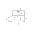
図4は従来の加熱乾燥式の水分計の構成を示している。なお、以後特に断らない限り「水分計」の語はこの加熱乾燥式水分計を指すものとする。
水分計の構成は大別して試料の重量を計測する重量計測部1と、重量計測の対象となっている試料を加熱乾燥させるための加熱部2とから成っている。試料の水分計測に当たっては重量計測部1の重量センサ3と接続する秤量皿4に載置された試料を、加熱源5により加熱乾燥し、加熱前の試料の重量と加熱乾燥後の試料の重量とから当該試料の水分を計測するよう構成されている。
FIG. 4 shows the configuration of a conventional heat drying moisture meter. Unless otherwise specified, the term “moisture meter” refers to this heat-drying moisture meter.
The configuration of the moisture meter is roughly divided into a
上述した水分計は、当然のことながら試料を加熱乾燥するための手段を有しているわけであるが、加熱乾燥式水分計を加熱方式から分類すると、以下の5つに分類され、これ以外の加熱乾燥方式は後述する本発明を除き現時点では存在していない。 The moisture meter described above has a means for heating and drying the sample as a matter of course. If the moisture drying type moisture meter is classified according to the heating method, it is classified into the following five, and other than this: There is currently no heat drying method except for the present invention described later.
(1)赤外線ランプ方式
赤外線ランプから発生する赤外線を試料の加熱乾燥用の熱源として利用する方式である。
(2)シーズヒーター方式
メタルシース或いはセラミックシースの中心に発熱線を固定することにより管状に形成されたシーズヒータを熱源とする方式である。
(3)ハロゲンランプ方式
ハロゲンランプから発する光ビームを試料の加熱手段として用いる方式である。
(4)電気抵抗方式
発熱抵抗体に対して通電してこの発熱抵抗体を発熱させ、この熱を試料の加熱乾燥用熱源として利用する方式である。
(5)マイクロ波方式
マグネトロンを利用して試料に含まれる水分に直接熱運動を加える方式であって、電子レンジと同じ加熱方式である。
(2) Seeds heater method This method uses a sheathed heater formed in a tubular shape by fixing a heating wire at the center of a metal sheath or ceramic sheath as a heat source.
(3) Halogen lamp method In this method, a light beam emitted from a halogen lamp is used as a heating means for the sample.
(4) Electric resistance method In this method, the heat generating resistor is energized to generate heat, and this heat is used as a heat source for heating and drying the sample.
(5) Microwave method This is a method in which a magnetron is used to add thermal motion directly to the moisture contained in the sample, and is the same heating method as in a microwave oven.
これら各種の加熱方式には一長一短があり、それぞれの使用条件に対応して使い分けられている。
なお、(1)乃至(3)の方式は何れも発熱源から輻射される赤外線を主たる加熱源としている。このため加熱源と加熱対象である試料、及び反射板、加熱源と計量部を仕切る透明板等の赤外線の輻射経路に汚れがあると試料の加熱乾燥の効率が低下し、かつ加熱温度の制御自体も不確かなものとなるという共通の問題点を有している。以下個々の方式の問題点について考察する。
These various heating methods have their merits and demerits, and are used properly according to the respective use conditions.
Note that all of the methods (1) to (3) use infrared rays radiated from a heat source as a main heating source. Therefore, if the infrared radiation path such as the heating source and the sample to be heated and the reflector, the transparent plate that partitions the heating source and the measuring section is contaminated, the efficiency of heating and drying of the sample is reduced, and the heating temperature is controlled. It has a common problem that it itself becomes uncertain. The problems of each method are discussed below.
まず(1)の赤外線ランプ方式は、熱源として比較的安価な赤外線ランプを使用するため経済性は比較的高いといえる。反面、試料を加熱乾燥するのに十分な赤外線を発するまでに時間がかかり、加熱乾燥に要する時間が長く、しかもランプの寿命が短いという欠点がある。またこの方式では殆どの装置に前記透明板として耐熱ガラス板が配置され、耐熱ガラス板の汚れによって上記加熱に関する問題が顕著である。 First, the infrared lamp method (1) uses a relatively inexpensive infrared lamp as a heat source, so it can be said that the economic efficiency is relatively high. On the other hand, it takes time to emit infrared rays sufficient for heating and drying the sample, and there is a disadvantage that the time required for heating and drying is long and the life of the lamp is short. In this method, a heat-resistant glass plate is disposed as the transparent plate in most apparatuses, and the problem relating to the heating is significant due to contamination of the heat-resistant glass plate.
(2)のシーズヒータ方式は、ランプの破損等による危険はないが、赤外線ランプと同様試料の加熱乾燥に時間がかかるという欠点がある。 The sheathed heater method (2) has no danger due to lamp breakage or the like, but has the disadvantage that it takes time to heat and dry the sample like an infrared lamp.
(3)のハロンゲンランプ方式は、試料の加熱乾燥の時間が短いという利点があるが、赤外線ランプの場合と同様、ランプの破損や、ランプ寿命が短いという問題がある。またハロゲンランプは高価であるとい経済的なディメリットもある。また(1)や(2)の方式と同様,試料からの揮発成分の付着等により短時間で加熱性能が低下し、例えば数回の測定で熱源、透明板部分を中心として清掃作業が必要となることが多い。 The Halongen lamp method (3) has the advantage that the time for heating and drying the sample is short, but there are problems such as breakage of the lamp and short lamp life as in the case of the infrared lamp. In addition, the halogen lamp has an economical disadvantage that it is expensive. In addition, similar to the methods (1) and (2), the heating performance deteriorates in a short time due to adhesion of volatile components from the sample. For example, the cleaning work is required centering on the heat source and the transparent plate in several measurements. Often becomes.
(4)の電気抵抗方式は加熱乾燥に必要な熱量としては不足であったり、必要な熱量を確保するためには電力の消費量が多くなって不経済である等の理由により、この方式は単独の構成は少なく、前記特許文献2の如く多くは他の方式との併用となっている。
The electrical resistance method of (4) is not sufficient as the amount of heat necessary for heating and drying, or because this method is uneconomical due to the consumption of electric power to secure the necessary amount of heat, this method is There are few independent configurations, and many are used in combination with other systems as in
(5)のマイクロ波方式は、マイクロ波により試料自体を直接発熱させるため、上記(1)から(4)の方式のように試料を外部から加熱する方式の欠点を克服することができる。即ち、試料を外部から加熱すると、加熱による乾燥は試料外部から進行するため、内部の水分が抜けにくいという共通の問題があるが、このマイクロ波方式では試料の水分に対して直接熱運動を加えるため、このような問題が生じない。しかし、水分の含有量の少ない試料の場合では測定に時間がかかる。またマグネトロンの構成が複雑であるため、小型化には限界があり、水分計としては大型かつ複雑高価な装置とならざるをえない。 In the microwave method of (5), the sample itself is directly heated by the microwave, so that the disadvantages of the method of heating the sample from the outside like the methods (1) to (4) can be overcome. In other words, when the sample is heated from the outside, drying by heating proceeds from the outside of the sample, so there is a common problem that moisture inside is difficult to escape, but this microwave method directly applies thermal motion to the moisture in the sample. Therefore, such a problem does not occur. However, in the case of a sample having a low water content, the measurement takes time. Moreover, since the structure of the magnetron is complicated, there is a limit to downsizing, and the moisture meter must be a large, complicated and expensive device.
以上の点からも明らかに推察できるように、加熱乾燥式の水分計においては、短時間での試料の均一な加熱乾燥という水分計の基本性能の確保と、商品としての装置の小型化および低価格化の両方を実現することが要望されている。因みに長時間に渡る試料の加熱乾燥は、例えば試料の溶解や昇華等を招き、結局正確な水分計測が不可能となってしまうという問題がある。 As can be clearly inferred from the above points, in the heat-drying type moisture meter, the basic performance of the moisture meter, that is, uniform heat-drying of the sample in a short time, is ensured, and the apparatus as a product is downsized and reduced. There is a demand for realizing both pricing. Incidentally, heating and drying of a sample for a long time causes, for example, dissolution or sublimation of the sample, and there is a problem that accurate moisture measurement becomes impossible after all.
本発明は上述した従来の加熱乾燥式水分計の問題点を解決するために構成されたものである。
即ち、本発明は、
試料を載置する秤量皿と、該秤量皿上の荷重を計測する重量計測部と、が備えられ、前記秤量皿に載置された試料を加熱乾燥し、加熱前の試料の重量と加熱乾燥後の試料の重量とから当該試料の水分を計測する水分計おいて、
前記秤量皿における試料載置面の上方領域内又は下方領域内のいずれかに、磁界を発生させる磁界発生部が配置され、
前記秤量皿が、導電性材料によって形成されて、前記磁界発生部の磁束による電磁誘導により渦電流が生じるように構成され、
前記重量計測部に、電磁平衡式の重量センサが備えられ、
前記電磁平衡式の重量センサには、磁気をシールドする磁気シールドが施されている構成とされている。
This invention is comprised in order to solve the trouble of the conventional heat drying type moisture meter mentioned above.
That is, the present invention is,
A weighing pan for placing the sample and a weight measuring unit for measuring a load on the weighing pan are provided, and the sample placed on the weighing pan is heated and dried, and the weight of the sample before heating and the heating drying In a moisture meter that measures the moisture of the sample from the weight of the later sample,
A magnetic field generator for generating a magnetic field is disposed in either the upper region or the lower region of the sample placement surface in the weighing pan ,
The weighing pan is formed of a conductive material, and is configured such that an eddy current is generated by electromagnetic induction by the magnetic flux of the magnetic field generation unit ,
The weight measuring unit includes an electromagnetic balance type weight sensor,
The electromagnetic balance type weight sensor is provided with a magnetic shield for shielding magnetism.
試料を載置する秤量皿の発熱により試料を加熱乾燥するので、試料を均一に然も短時間で加熱乾燥することができ、水分計測を正確に実施することができる。 Since the sample is heated and dried by the heat generated by the weighing pan on which the sample is placed, the sample can be heated and dried uniformly and in a short time, and moisture measurement can be accurately performed.
また、発熱部は秤量皿に限られるため、重量計測部に対する熱的影響を最小限に抑えることができ、この点からも計測の精度を向上させることができる。 Further, since the heat generating part is limited to the weighing pan, the thermal influence on the weight measuring part can be minimized, and the measurement accuracy can be improved from this point.
ランプ等を点灯する従来方式では熱ビームを照射する等の間接的な加熱方式であるため、試料以外の対象も加熱させてしまい、加熱乾燥に要するエネルギーのロスが大きかったが、本発明では秤量皿の熱で試料を加熱乾燥するため、発生した熱エネルギーの殆どは試料の加熱乾燥に利用でき、エネルギーロスを大幅に低減することが可能となり、経済性を向上させることができる。 Since the conventional method for lighting the lamp is an indirect heating system such as for irradiating the heat beam, subject other than the sample may cause by heating, but the loss of energy required for heating and drying is large, weighing in the present invention Since the sample is heat-dried by the heat of the dish, most of the generated thermal energy can be used for heat-drying the sample, energy loss can be greatly reduced, and economic efficiency can be improved.
従来のランプ方式では発熱源の熱劣化が避けられず、このためランプの寿命によるランプ交換もまた避けられない。さらにランプの破損の事故も発生する可能性があるのに対して、本発明の加熱源である磁界発生部はこのような経時的な劣化が殆ど無く、装置として半永久的な使用が可能であり、しかも水分計全体を低コストで製造することが可能となる。またランプの破損による怪我等の危険もない。 In the conventional lamp system, heat deterioration of the heat source is unavoidable, and therefore lamp replacement due to lamp life is also unavoidable. In addition, there is a possibility that the lamp may be damaged, whereas the magnetic field generation unit that is the heating source of the present invention is hardly deteriorated with time and can be used semi-permanently as a device. In addition, the entire moisture meter can be manufactured at low cost. There is no risk of injury due to lamp breakage.
熱源としてのランプ或いは他のヒータを使用するときは、熱源の大きさ或いは重量計測部に対する熱的影響の点から、熱源の配置位置は秤量皿上部側に限定されているが、磁界発生部を用いる場合には磁界発生部の配置にこのような限定は無く、秤量皿側面側、秤量皿下部側等にも配置可能であり、水分計としての設計の自由度が大幅に向上し、例えば装置の小型化等、装置の設計目的の実現が容易となる等、各種の効果を発揮することが可能となる。 When a lamp or other heater is used as a heat source, the heat source is located at the upper part of the weighing pan from the viewpoint of the thermal effect on the size of the heat source or the weight measurement unit. When used, there is no such limitation on the arrangement of the magnetic field generator, and it can be arranged on the side of the weighing pan, the lower side of the weighing pan, etc., and the degree of freedom in designing as a moisture meter is greatly improved. Various effects can be exhibited, such as the miniaturization of the apparatus and the realization of the design purpose of the apparatus.
コイル及び磁気回路から構成されている磁界発生部を、試料が載置される秤量皿の例えば上部空間に配置する。この磁界発生部に交流電流を流すことにより発生する磁界変化によって、対象物である秤量皿或いは秤量皿に近接配置された発熱部材に渦電流を発生させる。 A magnetic field generator composed of a coil and a magnetic circuit is disposed, for example, in an upper space of a weighing pan on which a sample is placed. An eddy current is generated in the weighing pan that is the object or a heating member that is disposed in proximity to the weighing pan by a change in the magnetic field that is generated by passing an alternating current through the magnetic field generator.
渦電流の発生により秤量皿或いは発熱部材はその構成材料の有する電気抵抗によりジュール発熱する。このジュール発熱を利用して秤量皿に載置されている試料を直接加熱乾燥する。 Due to the generation of eddy current, the weighing pan or the heating member generates Joule heat due to the electric resistance of the constituent material. Using this Joule heat generation, the sample placed on the weighing pan is directly heated and dried.
以下本発明の実施例を図面を参考に説明する。
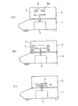
図1(A)乃至(C)は磁界発生部の配置位置が異なる構成を示す。
まず、主として図(A)を用いて説明する。
Embodiments of the present invention will be described below with reference to the drawings.
1A to 1C show configurations in which the arrangement positions of the magnetic field generation units are different.
First, description will be made mainly with reference to FIG.
図1(A)において、符号6は磁界発生部を示し、図示の構成では磁界発生部6は秤量皿4の上部空間に位置するよう加熱部2に配置されている。磁界発生部6は磁力を発生させるためのコイル6aとこのコイル6aに対する電流を制御する磁気回路から構成されている。
In FIG. 1A,
一方秤量皿4は発熱部としての機能も有している。即ち、秤量皿4は後述するように電磁誘導により発生する渦電流によりジュール発熱するように構成されている。秤量皿4の構成材料としては、例えば適当な電気抵抗値を有するステンレス等の鉄系金属により構成されている。
一方重量計測部1には電磁平衡式の秤量機構から成る重量センサ3が配置され、前記秤量皿4に載置された試料の重量の変化を計測する。
On the other hand, the weighing
On the other hand, the
以上の構成において、磁界発生部6に対して交流電流を通電すると、磁界発生部6からは交流電流の周波数に対応した時間変化のある交流磁界が導電性を有する秤量皿4に加えられることにより、秤量皿4に渦電流が発生する。即ち、交流磁界の印加により、導体である秤量皿4には電磁誘導により単位時間当たりの磁束の変化量に比例した電流、即ち渦電流が発生する。秤量皿4を構成する金属材料は固有の電気抵抗値を有しているので、この電気抵抗により渦電流は最終的にはジュール熱として消費され、導体である秤量皿4は発熱昇温する。
In the above configuration, when an alternating current is applied to the
上記発熱は、磁界内に配置された導体に対してのみ生じるので、導体として磁界に配置するものを秤量皿4のみにしておくことにより秤量皿4だけが発熱することになる。発熱した秤量皿4は、当該秤量皿4に配置された試料を直接加熱乾燥し、効率的な加熱乾燥を実現することができる。
Since the heat generation occurs only with respect to the conductor arranged in the magnetic field, only the weighing
上述のように秤量皿4が発熱することにより、次のような長所を得ることができる。
赤外線ランプ等の一次熱源による間接加熱によらず、秤量皿4に載置された試料を直接加熱することができるため、試料を均一かつ短時間で加熱乾燥することが可能となる。特に重量センサ3が電磁平衡式の場合には熱変化に弱いので、短時間での加熱乾燥は計測誤差を減少させることにもなる。
また、上記一次熱源による間接加熱の場合には結果的に試料以外に、試料が配置されている周囲の空気も加熱することになるため、エネルギーロスが多くなるが、本発明ではこのロスを最小限に止めることが可能で省電力化も可能である。
When the weighing
Since the sample placed on the weighing
Further, in the case of indirect heating by the primary heat source, as a result, the surrounding air where the sample is arranged is also heated in addition to the sample, resulting in an increase in energy loss. In the present invention, this loss is minimized. It is possible to limit it to the limit and to save power.
図1(B)は本発明の第2の実施例を示す。
この構成では磁界発生部(符号7で示す)を秤量皿4の側面に配置した構成を示している。
この実施例も含め、磁界発生部は発熱対象である秤量皿4が、当該磁界発生部が発生した磁束内に位置するように配置されていればよく、従ってこの条件が満たされるならば、磁界発生部を前記(A)の構成以外の位置に配置することも何ら問題はない。即ち、磁界発生部の配置位置が自由に選択できることは水分計設計の自由度を高めることになる。
FIG. 1B shows a second embodiment of the present invention.
In this configuration, a configuration in which a magnetic field generation unit (indicated by reference numeral 7) is arranged on the side surface of the weighing
Including this embodiment, it is only necessary that the weighing
(B)の構成は(A)の構成と相違し、磁界発生部7を秤量皿2の側面に配置した構成となっているが、例えば、(B)の構成及び後述する(C)の構成は、加熱部の高さを低くして水分計全体をコンパクトにする設計方針に対して対応可能であり、また(A)の構成は赤外線ランプ等を用いた従来の水分計の基本設計を利用して、製品価格を抑える場合等に適当な配置であるといえる。
The configuration of (B) is different from the configuration of (A) and has a configuration in which the
(C)は実施例3として磁界発生部(符号8で示す)を秤量皿4の下面に配置した構成を示している。この構成は水分計全体を最もコンパクトに構成することが可能である。但し、磁界発生部8が重量センサ3に対して最も近くに配置された構成でもあるため、後述の実施例の如く磁界からの影響を阻止するため、質量センサ3に磁気シールドを施すことが望ましい。
(C) shows a configuration in which a magnetic field generator (indicated by reference numeral 8) is arranged on the lower surface of the weighing
一方、電磁誘導方式の加熱においては、水分計にとって以下に示すような好ましからぬ現象が発生する。このためこのような現象から水分計を防護する措置を講ずることが望ましい。 On the other hand, in the electromagnetic induction heating, the following undesirable phenomenon occurs for the moisture meter. For this reason, it is desirable to take measures to protect the moisture meter from such phenomena.
まず、重量計測部1の質量センサ3が電磁平衡式質量センサである場合、この電磁平衡式質量センサは分解能の高い質量センサであるため、磁界発生部6、7、8からの交流磁界の影響も受けやすく、交流磁界の影響を受けると質量測定精度が低下することになる。従って、質量センサ3に対する磁気シールドを実施する必要がある。
First, when the
また秤量皿4等の発熱対象に交流磁界(一次磁束)が印加されると、発熱対象に発生する渦電流により二次磁束が発生し、この一次磁束と二次磁束とが干渉し、相互作用として電磁力が発生する。この電磁力により秤量皿4等の発熱対象が物理的に振動する等の現象が発生する場合がある。従って、発熱対象に交流磁界を印加しているときはこの発熱対象を固定する手段を設けることも考慮する。
Further, when an alternating magnetic field (primary magnetic flux) is applied to an object to be heated such as the weighing
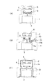
図2の構成(A)乃至(C)のうち、(B)及び(C)は上記問題に対処したものを、または(A)は発熱する対象を秤量皿以外の発熱専用の部材としこの発熱部材(発熱用部材)を介して秤量皿4を加熱する構成を示している。なお上記(A)乃至(C)の構成は何れも磁界発生部が加熱部2の上部に配置された場合を例に示しているので、以下磁界発生部を示す符号は図1の(A)に示す構成の磁界発生部と対応して符号6で示す。
Among the configurations (A) to (C) in FIG. 2, (B) and (C) are those that deal with the above-mentioned problem, or (A) is a heat-dedicated member other than the weighing pan and this heat generation. The structure which heats the weighing
まず(A)において符号9は発熱専用の部材(以下「発熱部材」とする)であって、秤量皿4の下部において、当該秤量皿4に近接して配置されている。磁界発生部6の磁束による渦電流によって発熱した発熱部材9の熱は近接位置する秤量皿4に伝熱され、秤量皿4はこの発熱部材9の熱により加熱される。なお、発熱部材9を秤量皿4の上部に配置し、主として発熱部材9の熱ビームで秤量皿4上の試料を直接加熱乾燥する構成とすることももとより可能である。
First, in (A),
上記構成では、発熱部材9は発熱専用の部材であって、他の機能は要求されていないので、効率的な発熱の観点のみから当該発熱部材9の構成材料選択をすることができる。一方秤量皿4も、自己の発熱を考慮せず秤量皿としての本来の機能を発揮すればよく、従って秤量皿4を構成する材料(金属材料)は、その電気抵抗値を考慮せず秤量皿として本来要求される機能、例えば耐食性、加工性等の観点からその構成材料を選択することができる。
In the above configuration, the
(B)の構成は発熱対象である秤量皿4を物理的に固定する手段を示す。前述のように、磁界発生部6からの一次磁束と、被加熱対象である秤量皿4に発生する渦電流に起因する二次磁束とが干渉し、相互作用として両者の間に電磁力が発生する。このため磁界発生部6による交流磁界が形成されているときは、固定装置により秤量皿4を固定(従ってこの間は試料の重量計測は行わない)し、電磁力による測定誤差が生じないようにする。
The structure of (B) shows a means for physically fixing the weighing
図2(B)の矢印10はこの秤量皿固定機構を示す。秤量皿固定機構10は、秤量皿4を昇降させる昇降機構11と、この昇降機構11により上昇した秤量皿4が当接する圧接部12とから構成される。図示の昇降機構は、回転により秤量皿4を昇降させるカム11aと、このカム11aを回転させるモータ11bとから構成されている。
The
上記構成においては、まず加熱乾燥前の試料の重量が計測される。次に磁界発生部6をONとする前に、昇降手段11により秤量皿4を上昇させ圧接部12に圧接固定する。この間、秤量皿4は重量センサ3から離れ、試料の重量は重量センサ3側には負荷されていない。この状態で磁界発生部6をONとして秤量皿4を発熱昇温させ、試料を加熱乾燥させる。予め設定された時間が経過すると、磁界発生部6をOFFし、かつ秤量皿4を下降させて試料の重量を計測する。次に再度秤量皿4を上昇固定させた後、磁界発生部6を再度ONして試料の加熱乾燥を行う。この操作を何度が繰り返し、加熱乾燥した試料の重量の計測値に変化が無くなった時点で、この計測値を試料の乾燥時の重量とし、この乾燥重量と前記加熱前の重量計測値とから当該試料の水分量を算出する。
なお、上記カムを用いた秤量皿昇降機構10はその構成の一例を示すものであり、もとよりこの機構に限定するものではない。
In the above configuration, first, the weight of the sample before heating and drying is measured. Next, before the
In addition, the weighing pan raising / lowering
(C)は磁気シールドに関する構成を示す。
符号13は重量計測部1内の重量センサ3を、磁界発生部6による磁力から防護するための磁気シールドである。重量センサ3が電磁平衡式センサである場合は特に磁気に対する対策を施し、磁力の悪影響による測定の誤差が発生するのを防止するように構成することが望ましい。
(C) shows the structure regarding a magnetic shield.
なお、磁気シールド方法としては例えば、珪素鋼板、パーマロイ、アモルファス金属等を単体或いは積層したものをシールド材として利用する等、従来から用いられている技術を利用することができる。なお、同じ材料であればシールド材の厚さ及び積層枚数に比例して磁気シールド性能が向上することが知られている。 In addition, as a magnetic shielding method, for example, a conventionally used technique such as using a single or laminated silicon steel plate, permalloy, amorphous metal or the like as a shielding material can be used. It is known that the same material improves the magnetic shielding performance in proportion to the thickness of the shielding material and the number of laminated layers.
次に符号14は加熱部2側に設けた磁気シールドである。この磁気シールド14は特に磁束が秤量皿4以外の部材に影響しないようにするためのもであり、秤量皿4のみを発熱させ、他の部材が勝手に発熱してしまうのを防止する目的も有している。なお、シールド材としては、特別な事情が無い限り符号13に示すものと同じものを使用すればよい。
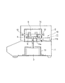
図3は上記各実施例を一つの装置で実現するようにした水分計の構成例を示す。なお、この構成例では秤量皿4の下部に発熱専用の発熱部材9が配置され、秤量皿4はこの発熱部材9の熱により間接的に加熱される構成となっている。従って秤量皿の昇降機構11は図2(B)におけるような秤量皿4自体に加わる電磁力に対応するのではなく、発熱部材9に発生する電磁力により秤量皿4が間接的に影響されるのを防止するための機構として機能する。
FIG. 3 shows a configuration example of a moisture meter in which each of the above embodiments is realized by one apparatus. In this configuration example, a
本発明に係る加熱乾燥式水分計は、加熱手段が事実上メンテナンスフリーであり、ランプの破損等の事故も生じないため、従来は研究所等、装置使用者が水分計に対して高い知識も持っている者が使用する環境以外では使用が困難であったものが、例えば食品の製造工程、セメントの製造工程等において適宜設置してサンプリングした対象物を現場において、その製造工程に従事する者が適宜水分計測を行う装置として構成することにより、装置の汎用性を高めることができる。 Since the heating and drying type moisture meter according to the present invention is virtually maintenance-free for heating means and does not cause accidents such as lamp breakage, a laboratory user or the like conventionally has a high knowledge of moisture meters. Those who are difficult to use in environments other than those used by those who have them, for example, those who are placed in the production process of food, cement, etc. By configuring as a device that appropriately measures moisture, the versatility of the device can be enhanced.
1 重量計測部
2 加熱部
3 重量センサ
4 秤量皿
6、7、8 磁界発生部
9 発熱部材(発熱用部材)
10 固定機構
11 昇降手段
11a カム
11b モータ
12 圧接部
13、14 磁気シールド
DESCRIPTION OF
DESCRIPTION OF
Claims (6)
前記秤量皿における試料載置面の上方領域内又は下方領域内のいずれかに、磁界を発生させる磁界発生部が配置され、
前記秤量皿が、導電性材料によって形成されて、前記磁界発生部の磁束による電磁誘導により渦電流が生じるように構成され、
前記重量計測部に、電磁平衡式の重量センサが備えられ、
前記電磁平衡式の重量センサには、磁気をシールドする磁気シールドが施されている、
ことを特徴とする水分計。 A weighing pan for placing the sample and a weight measuring unit for measuring a load on the weighing pan are provided, and the sample placed on the weighing pan is heated and dried, and the weight of the sample before heating and the heating drying In a moisture meter that measures the moisture of the sample from the weight of the later sample,
A magnetic field generator for generating a magnetic field is disposed in either the upper region or the lower region of the sample placement surface in the weighing pan ,
The weighing pan is formed of a conductive material, and is configured such that an eddy current is generated by electromagnetic induction by the magnetic flux of the magnetic field generation unit ,
The weight measuring unit includes an electromagnetic balance type weight sensor,
The electromagnetic balance type weight sensor is provided with a magnetic shield for shielding magnetism,
Moisture meter characterized by that.
前記秤量皿は、固定機構に関連付けられ、The weighing pan is associated with a securing mechanism;
前記固定機構は、前記秤量皿が電磁誘導により発熱している間、該秤量皿を固定するように設定されている、The fixing mechanism is set to fix the weighing pan while the weighing pan is heated by electromagnetic induction.
ことを特徴とする水分計。Moisture meter characterized by that.
前記磁界発生部と前記秤量皿とが、磁気をシールドする磁気シールドにより囲まれて、該磁界発生部からの磁束が該秤量皿にのみ作用するように設定されている、 The magnetic field generator and the weighing pan are surrounded by a magnetic shield that shields magnetism, and the magnetic flux from the magnetic field generator is set so as to act only on the weighing pan.
ことを特徴とする水分計。Moisture meter characterized by that.
前記秤量皿に発熱用部材が近接配置され、A heating member is disposed close to the weighing pan,
前記発熱用部材は、前記磁界発生部の磁束による電磁誘導によって発熱するように設定され、The heat generating member is set so as to generate heat by electromagnetic induction by the magnetic flux of the magnetic field generating unit,
前記発熱用部材が、その発熱により前記秤量皿を加熱するように設定されている、The heating member is set to heat the weighing pan by the heat generation;
ことを特徴とする水分計。Moisture meter characterized by that.
前記磁界発生部は、秤量皿の上方領域に配置されている、 The magnetic field generator is disposed in the upper region of the weighing pan.
ことを特徴とする水分計。Moisture meter characterized by that.
前記磁界発生部が、前記秤量皿と前記重量計測部との間に配置されている、The magnetic field generating unit is disposed between the weighing pan and the weight measuring unit,
ことを特徴とする水分計。Moisture meter characterized by that.
Priority Applications (1)
| Application Number | Priority Date | Filing Date | Title |
|---|---|---|---|
| JP2008154925A JP5215744B2 (en) | 2008-06-13 | 2008-06-13 | Moisture meter |
Applications Claiming Priority (1)
| Application Number | Priority Date | Filing Date | Title |
|---|---|---|---|
| JP2008154925A JP5215744B2 (en) | 2008-06-13 | 2008-06-13 | Moisture meter |
Related Child Applications (1)
| Application Number | Title | Priority Date | Filing Date |
|---|---|---|---|
| JP2013039024A Division JP2013137323A (en) | 2013-02-28 | 2013-02-28 | Moisture meter |
Publications (2)
| Publication Number | Publication Date |
|---|---|
| JP2009300246A JP2009300246A (en) | 2009-12-24 |
| JP5215744B2 true JP5215744B2 (en) | 2013-06-19 |
Family
ID=41547305
Family Applications (1)
| Application Number | Title | Priority Date | Filing Date |
|---|---|---|---|
| JP2008154925A Expired - Fee Related JP5215744B2 (en) | 2008-06-13 | 2008-06-13 | Moisture meter |
Country Status (1)
| Country | Link |
|---|---|
| JP (1) | JP5215744B2 (en) |
Families Citing this family (8)
| Publication number | Priority date | Publication date | Assignee | Title |
|---|---|---|---|---|
| CN102564887B (en) * | 2010-12-16 | 2013-07-10 | 大连理工大学 | High heating rate controllable thermal balance |
| US10765090B2 (en) * | 2015-04-24 | 2020-09-08 | A&D Company, Limited | Animal weighing scale |
| CN110967276A (en) * | 2018-09-30 | 2020-04-07 | 上海育语智能科技有限公司 | Electronic dust-falling cylinder |
| CN110967275B (en) * | 2018-09-30 | 2025-11-11 | 江苏尘控智能科技有限公司 | Electronic dust fall tube |
| CN109900587A (en) * | 2019-03-09 | 2019-06-18 | 徐立杰 | A kind of device of the measurement heat-sensitive materials water content with multiple measurement positions |
| CN109916764A (en) * | 2019-03-22 | 2019-06-21 | 深圳冠亚水分仪科技有限公司 | A kind of instrument visualizing quick water content detection |
| CN112021641B (en) * | 2020-07-10 | 2022-04-29 | 张家口卷烟厂有限责任公司 | On-line moisture meter calibration system for tobacco shred making link |
| GB202303542D0 (en) * | 2023-03-10 | 2023-04-26 | Metryx Ltd | Apparatus for measuring the mass and/or the change in mass of an object |
Family Cites Families (7)
| Publication number | Priority date | Publication date | Assignee | Title |
|---|---|---|---|---|
| JPS5280096A (en) * | 1975-12-26 | 1977-07-05 | Shimadzu Corp | Moisture measuring device |
| JPH0389139A (en) * | 1989-09-01 | 1991-04-15 | Ebara Infilco Co Ltd | Measurement of moisture |
| JPH051987A (en) * | 1991-06-26 | 1993-01-08 | Shimadzu Corp | Measuring device for water or volatile matter |
| JPH06273320A (en) * | 1993-03-19 | 1994-09-30 | Olympus Optical Co Ltd | Automatic analyzing method and displaying method of electrophoretic image |
| JP2000221128A (en) * | 1999-01-29 | 2000-08-11 | Ricoh Co Ltd | Sample dish position correction device |
| JP2002280789A (en) * | 2001-03-19 | 2002-09-27 | Tdk Corp | Magnetic shield and induction heater using it |
| PL1876431T3 (en) * | 2006-07-07 | 2014-01-31 | Mettler Toledo Ag | Measuring apparatus for gravimetrical determination of moisture |
-
2008
- 2008-06-13 JP JP2008154925A patent/JP5215744B2/en not_active Expired - Fee Related
Also Published As
| Publication number | Publication date |
|---|---|
| JP2009300246A (en) | 2009-12-24 |
Similar Documents
| Publication | Publication Date | Title |
|---|---|---|
| JP5215744B2 (en) | Moisture meter | |
| CN100569032C (en) | induction heating cooker | |
| KR100873241B1 (en) | Cooking unit with temperature sensor assembly and radiant electric heater | |
| JPH0658554A (en) | Method and device for indicating abnormal thermal stress state in heating surface manufactured from glass ceramic or similar material | |
| ES2666277T3 (en) | Method for detecting the presence of a kitchen utensil on a plate for induction cooking and a plate using said method | |
| ES2267657T3 (en) | PROCEDURE AND DEVICE FOR DETECTION OF THE TEMPERATURE OF A KITCHEN UTENSIL. | |
| JP2013137323A (en) | Moisture meter | |
| JP4345504B2 (en) | Induction heating cooker | |
| JP5045171B2 (en) | Electric rice cooker | |
| JP2010027314A (en) | Induction cooker | |
| JP2007517189A (en) | Temperature sensor based on resistance measurement and radiation heater comprising such a temperature sensor | |
| JP5641339B2 (en) | Infrared sensor device and induction heating cooker provided with the same | |
| JP5459080B2 (en) | Induction heating cooker | |
| JP2018029010A (en) | Induction heating cooker | |
| JP6506568B2 (en) | Induction cooker | |
| JP2003302324A (en) | Moisture meter | |
| KR100898551B1 (en) | Cooker using activated carbon fiber heating element | |
| CN220958561U (en) | Electromagnetic oven | |
| KR102735430B1 (en) | Electric range using infrared temperature sensor and temperature measurement method using thereof | |
| CN201054814Y (en) | Overheat protector for magnet exciting coil of electromagnetic oven | |
| CN221227775U (en) | Coil panel and cooking device | |
| US20070062930A1 (en) | Method of controlling boiling level | |
| WO2015096927A1 (en) | An induction cooker, the safe utilization of which is provided | |
| KR20010039530A (en) | Cooking heater device | |
| JP5301046B2 (en) | Induction heating cooker |
Legal Events
| Date | Code | Title | Description |
|---|---|---|---|
| A621 | Written request for application examination |
Free format text: JAPANESE INTERMEDIATE CODE: A621 Effective date: 20110526 |
|
| RD03 | Notification of appointment of power of attorney |
Free format text: JAPANESE INTERMEDIATE CODE: A7423 Effective date: 20120118 |
|
| A521 | Request for written amendment filed |
Free format text: JAPANESE INTERMEDIATE CODE: A523 Effective date: 20120214 |
|
| A131 | Notification of reasons for refusal |
Free format text: JAPANESE INTERMEDIATE CODE: A131 Effective date: 20121127 |
|
| A977 | Report on retrieval |
Free format text: JAPANESE INTERMEDIATE CODE: A971007 Effective date: 20121128 |
|
| A521 | Request for written amendment filed |
Free format text: JAPANESE INTERMEDIATE CODE: A523 Effective date: 20130122 |
|
| TRDD | Decision of grant or rejection written | ||
| A01 | Written decision to grant a patent or to grant a registration (utility model) |
Free format text: JAPANESE INTERMEDIATE CODE: A01 Effective date: 20130212 |
|
| A61 | First payment of annual fees (during grant procedure) |
Free format text: JAPANESE INTERMEDIATE CODE: A61 Effective date: 20130301 |
|
| R150 | Certificate of patent or registration of utility model |
Ref document number: 5215744 Country of ref document: JP Free format text: JAPANESE INTERMEDIATE CODE: R150 Free format text: JAPANESE INTERMEDIATE CODE: R150 |
|
| FPAY | Renewal fee payment (event date is renewal date of database) |
Free format text: PAYMENT UNTIL: 20160308 Year of fee payment: 3 |
|
| R250 | Receipt of annual fees |
Free format text: JAPANESE INTERMEDIATE CODE: R250 |
|
| R250 | Receipt of annual fees |
Free format text: JAPANESE INTERMEDIATE CODE: R250 |
|
| R250 | Receipt of annual fees |
Free format text: JAPANESE INTERMEDIATE CODE: R250 |
|
| LAPS | Cancellation because of no payment of annual fees |