JP5212632B2 - Welding equipment - Google Patents
Welding equipment Download PDFInfo
- Publication number
- JP5212632B2 JP5212632B2 JP2008219712A JP2008219712A JP5212632B2 JP 5212632 B2 JP5212632 B2 JP 5212632B2 JP 2008219712 A JP2008219712 A JP 2008219712A JP 2008219712 A JP2008219712 A JP 2008219712A JP 5212632 B2 JP5212632 B2 JP 5212632B2
- Authority
- JP
- Japan
- Prior art keywords
- welding
- station
- blank
- blank material
- positioning
- Prior art date
- Legal status (The legal status is an assumption and is not a legal conclusion. Google has not performed a legal analysis and makes no representation as to the accuracy of the status listed.)
- Expired - Fee Related
Links
Images


Classifications
-
- B—PERFORMING OPERATIONS; TRANSPORTING
- B23—MACHINE TOOLS; METAL-WORKING NOT OTHERWISE PROVIDED FOR
- B23K—SOLDERING OR UNSOLDERING; WELDING; CLADDING OR PLATING BY SOLDERING OR WELDING; CUTTING BY APPLYING HEAT LOCALLY, e.g. FLAME CUTTING; WORKING BY LASER BEAM
- B23K37/00—Auxiliary devices or processes, not specially adapted to a procedure covered by only one of the preceding main groups
- B23K37/04—Auxiliary devices or processes, not specially adapted to a procedure covered by only one of the preceding main groups for holding or positioning work
- B23K37/047—Auxiliary devices or processes, not specially adapted to a procedure covered by only one of the preceding main groups for holding or positioning work moving work to adjust its position between soldering, welding or cutting steps
-
- B—PERFORMING OPERATIONS; TRANSPORTING
- B23—MACHINE TOOLS; METAL-WORKING NOT OTHERWISE PROVIDED FOR
- B23K—SOLDERING OR UNSOLDERING; WELDING; CLADDING OR PLATING BY SOLDERING OR WELDING; CUTTING BY APPLYING HEAT LOCALLY, e.g. FLAME CUTTING; WORKING BY LASER BEAM
- B23K26/00—Working by laser beam, e.g. welding, cutting or boring
- B23K26/08—Devices involving relative movement between laser beam and workpiece
- B23K26/0869—Devices involving movement of the laser head in at least one axial direction
- B23K26/0876—Devices involving movement of the laser head in at least one axial direction in at least two axial directions
-
- B—PERFORMING OPERATIONS; TRANSPORTING
- B23—MACHINE TOOLS; METAL-WORKING NOT OTHERWISE PROVIDED FOR
- B23K—SOLDERING OR UNSOLDERING; WELDING; CLADDING OR PLATING BY SOLDERING OR WELDING; CUTTING BY APPLYING HEAT LOCALLY, e.g. FLAME CUTTING; WORKING BY LASER BEAM
- B23K26/00—Working by laser beam, e.g. welding, cutting or boring
- B23K26/20—Bonding
- B23K26/21—Bonding by welding
- B23K26/24—Seam welding
- B23K26/26—Seam welding of rectilinear seams
-
- B—PERFORMING OPERATIONS; TRANSPORTING
- B23—MACHINE TOOLS; METAL-WORKING NOT OTHERWISE PROVIDED FOR
- B23K—SOLDERING OR UNSOLDERING; WELDING; CLADDING OR PLATING BY SOLDERING OR WELDING; CUTTING BY APPLYING HEAT LOCALLY, e.g. FLAME CUTTING; WORKING BY LASER BEAM
- B23K37/00—Auxiliary devices or processes, not specially adapted to a procedure covered by only one of the preceding main groups
- B23K37/04—Auxiliary devices or processes, not specially adapted to a procedure covered by only one of the preceding main groups for holding or positioning work
- B23K37/0408—Auxiliary devices or processes, not specially adapted to a procedure covered by only one of the preceding main groups for holding or positioning work for planar work
-
- B—PERFORMING OPERATIONS; TRANSPORTING
- B23—MACHINE TOOLS; METAL-WORKING NOT OTHERWISE PROVIDED FOR
- B23K—SOLDERING OR UNSOLDERING; WELDING; CLADDING OR PLATING BY SOLDERING OR WELDING; CUTTING BY APPLYING HEAT LOCALLY, e.g. FLAME CUTTING; WORKING BY LASER BEAM
- B23K2101/00—Articles made by soldering, welding or cutting
- B23K2101/18—Sheet panels
Description
本発明は、複数のブランク材を互いに溶接する溶接加工装置に関する。 The present invention relates to a welding apparatus for welding a plurality of blank materials to each other.
複数の板状のブランク材を互いに溶接する場合、各ブランク材の端縁を互いに突き合わせるように治具を用いて位置決めし、次いで当該突き合わせ部分をレーザ溶接により接合するのが一般的である。
このような溶接を行う溶接加工装置において、レーザ溶接そのものは比較的短時間で完了することができるが、これに比べて、ブランク材の搬入や位置決めは、時間がかかるものである。このため、ブランク材の搬入、位置決め、レーザ溶接、及び搬出までの工程を、同一場所にて行うと、全体としての作業時間は、一番時間のかかる工程に引きずられることになる。
When welding a plurality of plate-shaped blank materials to each other, it is common to position them using a jig so that the edges of each blank material abut each other, and then join the abutted portions by laser welding.
In a welding processing apparatus that performs such welding, laser welding itself can be completed in a relatively short time, but in comparison with this, it takes time to carry in and position the blank material. For this reason, if the process up to carrying in, positioning, laser welding, and carrying out the blank material is performed at the same place, the entire work time is dragged to the process that takes the longest time.
そこで、特許文献1に示される溶接装置においては、複数の溶接ステーションを搬送ラインと平行に配置して、一の溶接ステーションで溶接を行っている間に他の溶接ステーションで治具パレットの搬入及び位置決めを行い、その一の溶接ステーションでの溶接が完了すると、他の溶接ステーションで溶接を行うように構成されている。この溶接装置によれば、全体の作業時間を短縮することができる。
しかし、特許文献1に示される溶接装置においては、同じ仕様のブランク材の同じ部分に溶接を行う場合であっても、同じ機能を持った2つの溶接ステーションを設ける必要があるため、スペース的に不利となる。2つの溶接ステーションをカバーする溶接用の加工ヘッドが必要となるため、コスト的にも不利となる。
本発明はこのような事情を考慮してなされたもので、その目的は、必要とする溶接ステーションの数を減らし、スペース的にもコスト的にも有利な溶接加工装置を提供することにある。
However, in the welding apparatus shown in
The present invention has been made in view of such circumstances, and an object of the present invention is to provide a welding apparatus that reduces the number of required welding stations and is advantageous in terms of space and cost.
本発明は、前記の目的を達成するために創案されたものである。本発明の請求項1の溶接加工装置は、少なくとも第1ブランク材と第2ブランク材を含む複数のブランク材を互いに突き合わせて溶接する溶接加工装置であって、前記ブランク材を相互に溶接する溶接ヘッドを有する溶接ステーションと、前記溶接ステーションの一側に配置された第1位置決めステーションと、前記溶接ステーションの他側に配置された第2位置決めステーションと、前記複数のブランク材を同テーブルの予め定められた位置に固定する固定装置を有すると共に、前記位置決めステーションと前記溶接ステーションとに移動可能な第1及び第2テーブルと、前記第1テーブル及び第2テーブル上の予め定められた位置に突出可能なストッパ、及び当該各テーブル上の前記ブランク材が前記ストッパに当接するように同ブランク材を押圧する押圧部材を有する位置決め装置と、溶接前の前記複数のブランク材が載置される搬入ステーションと、前記複数のブランク材が溶接された完成品が載置される搬出ステーションと、前記搬入ステーション上のブランク材を、前記位置決めステーションにある前記第1テーブルまたは第2テーブルの上に移動する第1移動装置と、前記溶接ステーションで溶接が完了した後に、前記位置決めステーションに移動した前記第1テーブルまたは第2テーブル上の完成品を、前記搬出ステーションに移動する第2移動装置と、を備え、前記第1テーブルが前記第1位置決めステーションに移動されたときに前記第2テーブルが前記溶接ステーションに移動され、前記第1テーブルが前記溶接ステーションに移動されたときに前記第2テーブルが前記第2位置決めステーションに移動されるように構成され、前記第1テーブルまたは第2テーブルが対応する前記位置決めステーションに移動したときに、前記第1ブランク材を前記位置決め装置により予め定められた位置に配置し、次いで同第1ブランク材を前記固定装置により同テーブルに固定し、さらに同第1ブランク材に第2ブランク材を突き合わせるべく押圧させた状態で同第2ブランク材を前記固定装置により同テーブルに固定させ、同テーブルと共に前記溶接ステーションに移動させ、前記溶接ヘッドにより互いに溶接されるように構成されたことを特徴とする。
The present invention has been devised to achieve the above object. The welding processing apparatus according to
請求項2の溶接加工装置は、請求項1において、前記テーブルが、前記第1ブランク材が前記固定装置により同テーブルに固定された後、前記第1ブランク材における前記第2ブランク材が突き合わされる辺の両側部近傍に、前記第2ブランク材が前記第1ブランク材の上方に乗り上げることを防止するガイドを備えたことを特徴とする。
請求項3の溶接加工装置は、請求項1において、前記固定装置が、前記複数のブランク材の下面をそれぞれ吸着する吸着装置を備えていることを特徴とする。
A welding apparatus according to a second aspect is the welding apparatus according to the first aspect , wherein the second blank material in the first blank material is abutted after the first blank material is fixed to the table by the fixing device. A guide for preventing the second blank material from climbing over the first blank material is provided in the vicinity of both sides of the side.
According to a third aspect of the present invention, there is provided a welding apparatus according to the first aspect, wherein the fixing device includes an adsorption device that adsorbs the lower surfaces of the plurality of blank materials.
請求項4の溶接加工装置は、請求項3において、前記吸着装置が、前記テーブルに装着された磁気式であることを特徴とする。 According to a fourth aspect of the present invention, there is provided a welding apparatus according to the third aspect , wherein the adsorption device is a magnetic type mounted on the table.
本発明の請求項1の溶接加工装置において、ブランク材が固定される第1及び第2のテーブルを有し、これらのテーブルが位置決めステーションと溶接ステーションと順に移動し、そして溶接ステーションにおいて一方のテーブル上に固定されたブランク材を溶接する作業が行われているときに、位置決めステーションにおいて他方のテーブル上にブランク材を位置決め・固定する作業が行われる。したがって、ブランク材の溶接と位置決めを同時に行うことができるので、全体の作業時間を短縮できる。しかも、ブランク材に対して同じ溶接を行う限り、溶接ステーションは1つで足りるので、上述の従来装置に比べてスペース的に格段に有利である。
The welding processing apparatus according to
また、前記第1及び第2テーブルの一方が前記溶接ステーションにあって、そのテーブル上のブランク材の溶接作業が行われる。その間、前記第1及び第2テーブルの他方が前記位置決めステーションにあって、前記第2移動装置が、前記位置決めステーションに移動したテーブル上の完成品を前記搬出ステーションに移動し、前記第1移動装置が、前記搬入ステーションのブランク材を前記位置決めステーションにあるテーブル上に移動する。したがって、ブランク材の搬入及び完成品の搬出も含めて、全体としても作業時間を短縮することができる。 Also, one of the first and second tables is in the said welding station, welding of the blank on the table is performed. Meanwhile, the other of the first and second tables is in the positioning station, and the second moving device moves the finished product on the table moved to the positioning station to the unloading station, and the first moving device. Moves the blank material of the loading station onto the table at the positioning station. Therefore, the work time can be shortened as a whole, including carrying in blank materials and carrying out finished products.
さらに、第1テーブルが第1位置決めステーションに移動されたときに第2テーブルが溶接ステーションに移動され、第1テーブルが溶接ステーションに移動されたときに第2テーブルが第2位置決めステーションに移動される。しかも、第1位置決めステーションと第2位置決めステーションは、溶接ステーションを挟んで反対側に配置されているので、両ステーションを平面的に配置することができ、これにより装置の高さを小さく抑えることができる。 Further , the second table is moved to the welding station when the first table is moved to the first positioning station, and the second table is moved to the second positioning station when the first table is moved to the welding station. . In addition, since the first positioning station and the second positioning station are arranged on the opposite sides of the welding station, both stations can be arranged in a plane, thereby suppressing the height of the apparatus to be small. it can.
前記ブランク材は、前記テーブルに備えられた位置決め装置により、テーブル上の定められた位置に位置決めされる。 Before SL blank is by a provided positioning device to the table is positioned in a defined position on the table.
当該位置決めは、テーブル上に予め定められた位置にストッパを突出させ、前記ブランク材が前記ストッパに当接するように同ブランク材が前記押圧部材により押圧されて、実行される。
具体的には、第1ブランク材を前記位置決め装置より位置決めし、次いで同第1ブランク材を前記固定装置によりテーブルに固定し、さらに同第1ブランク材に第2ブランク材を突き合わせるべく押圧させた状態で同第2ブランクを前記固定装置によりテーブルに固定することにより、両ブランク材がテーブル上に位置決めされ、かつ固定される。したがって、第1ブランク材に対して第2ブランク材を精度良く位置決めすることができる。
The positioning, is projected stopper at a predetermined position on the tables, the blank as the blank comes into contact with the stopper is pressed by the pressing member, it is performed.
Specifically, the first blank material is positioned by the positioning device, and then the first blank material is fixed to the table by the fixing device, and further, the first blank material is pressed to abut the second blank material. In this state, the second blank is fixed to the table by the fixing device, so that both blank materials are positioned and fixed on the table. Therefore, the second blank material can be accurately positioned with respect to the first blank material.
請求項2の溶接加工装置において、第1ブランク材が固定装置によりテーブルに固定された後、前記第2ブランク材が前記第1ブランク材に突き合わされる際に、第2ブランク材が第1ブランク材の上方に乗り上げようとしても、テーブルに備えられた前記ガイドによりそのような乗り上げが確実に防止される。
請求項3の溶接加工装置において、前記固定装置が、各ブランク材の下面を吸着する吸着装置を備えているので、ブランク材の上面にクランプ等が突出しない。これにより、レーザ溶接を行う前記溶接ヘッドの移動に制約がなく、同溶接ヘッドの高速移動が可能となる。
3. The welding apparatus according to
In the welding processing apparatus according to
請求項4の溶接加工装置において、前記固定装置が、各テーブルに装着された磁気式であるので、ブランク材の下面を吸着及び非吸着を簡単に切り換えることができる。
In the welding processing apparatus according to
以下、図面を参照して本発明を実施するための最良の形態について説明する。
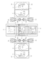
まず、第1の実施形態を図1〜図8に従って説明する。図1は第1の実施形態に係る溶接加工装置を示す平面図、図2は図1の溶接ステーション及び位置決めステーションの拡大図、図3は図2の右側面図、図4及び図5は本溶接加工装置のテーブルにおける位置決め装置を示す平面図、図6は図5のVI部の拡大図、図7は図6のVII−VII線に沿う矢視断面図、図8は図7のVIII−VIII線に沿う矢視断面図である。
The best mode for carrying out the present invention will be described below with reference to the drawings.
First, a first embodiment will be described with reference to FIGS. 1 is a plan view showing a welding apparatus according to the first embodiment, FIG. 2 is an enlarged view of a welding station and a positioning station of FIG. 1, FIG. 3 is a right side view of FIG. 2, and FIGS. FIG. 6 is an enlarged view of the VI part of FIG. 5, FIG. 7 is a cross-sectional view taken along the line VII-VII of FIG. 6, and FIG. It is arrow sectional drawing which follows the VIII line.
本溶接加工装置は、図1に示されるように、溶接ステーション2と、同溶接ステーション2の一側に配置された第1位置決めステーション4と、他側に配置された第2位置決めステーション6を備えている。これらのステーション2,4及び6に亘ってガイド部材としてのレール8が設けられており、同レール上8に第1テーブル10と第2テーブル12が案内されている。第1テーブル10は、同レール8に沿って第1位置決めステーション4と溶接ステーション2とを移動可能であり、第2テーブル12は、同レール8に沿って溶接ステーション2と第2位置決めステーション6とを移動可能である。溶接ステーション2には、ブランク材Bを溶接する溶接装置14が設けられている。各テーブル10及び12は、詳細は後述するが、ブランク材Bをテーブル上に位置決めし、かつ固定する機能を有している。
As shown in FIG. 1, the present welding processing apparatus includes a
溶接ステーション2の別の一側には、ブランク材Bを搬入する搬入ステーション16が配置され、他側には、ブランク材Bの溶接を完了した完成品Cを搬出する搬出ステーション18が配置されている。搬入ステーション16と位置決めステーション4及び6との間には、それぞれ搬入ステーション16上のブランク材Bを位置決めステーション4及び6に移動する第1移動装置としてのロボット20及び22がそれぞれ配置されている。また搬出ステーション18と位置決めステーション4及び6との間には、それぞれ位置決めステーション4及び6上のブランク材Bの溶接を完了した完成品Cを搬出ステーション18に移動する第2移動装置としてのロボット24及び26がそれぞれ配置されている。なお、各ロボット20,24,26,28はそれぞれ先端にブランク材Bを吸着する吸着部20a,22a,24a,26aを有している。
On another side of the
搬入ステーション16には、上面を2つに分割され、軸28を中心に回転できるターンテーブル30が設けられ、搬出ステーション18には、上面を2つに分割され、軸32を中心に回転できるターンテーブル34が設けられている。
ここで、第1及び第2テーブル10及び12と、各ロボット20,22,24,26と、各ターンテーブル20及び34の作動を互いに関連付けて説明する。
The
Here, the operations of the first and second tables 10 and 12, the
ターンテーブル30は、図左半分の所定位置に所定数重ねられたブランク材Bが載置されると、回転し、その載置されたブランク材Bがターンテーブル30の図右半分に移動する。ターンテーブル30の左半分は空になると直ぐに次の所定数重ねられたブランク材Bが載置される。そして、ターンテーブル30の図右半分が空になると、ターンテーブル30は回転して、ターンテーブルの図右半分には常にブランク材Bが載置された状態を保たれる。
The
今、第1テーブル10が空の状態で第1位置決めステーション4にあり、かつ第2テーブル12が空の状態で溶接ステーション2にあるとする。まず、ロボット20が、ターンテーブル30の図右半分にあるブランク材Bを吸着部20aにより吸着して、第1テーブル10上に載置する。第1テーブル10上において、ブランク材Bは予め定められた位置に位置決めされて固定された後、同第1テーブル10が溶接ステーション2に移動する。なお、このとき、第2テーブル12は、図1の2点鎖線12aで示すように、第2位置決めステーション6に移動する。
Now, assume that the first table 10 is in the
次いで、溶接ステーション2において、溶接装置14により、第1テーブル10上のブランク材Bをお互いに溶接する作業が実行される。その間、ロボット22が、ターンテーブルの図右半分にあるブランク材を吸着部22aにより吸着して、第2位置決めステーション6にある第2テーブル12上に載置する。
溶接ステーション2における溶接作業が完了し、かつ第2位置決めステーション6におけるブランク材Bの載置が完了すると、完成品Cを載せた第1テーブル10が再び第1位置決めステーション4に移動すると共に、ブランク材Bを載せた第2テーブルが溶接ステーション2に移動する。
Next, in the
When the welding operation at the
第1位置決めステーション4においては、ロボット24が、第1テーブル10上にある完成品Cを吸着部24aにより吸着して、搬出ステーション18のターンテーブル34の図左半分上に移動する。なお、完成品Cは、ターンテーブル34の図左半分に所定数重ねられると、ターンテーブル34が回転して、ターンテーブル34の図右半分に移動し、作業者あるいは他のロボットによる運び出しを待つ。さらにロボット20が、ターンテーブル30の右半分にあるブランク材Bを吸着部20aにより吸着して、第1テーブル10上に移動する。そして、第1テーブル10において、ブランク材Bが予め定められた位置に位置決めされて固定される作業が実行される。
In the
溶接ステーション2においては、溶接装置14により、第2テーブル12上のブランク材Bをお互いに溶接する作業が実行される。
そして、第1位置決めステーション4及び溶接ステーション2での作業が完了すると、第1テーブル10は溶接ステーション2に移動し、第2テーブル12は第2位置決めステーション6に移動する。
In the
When the operations at the
第2位置決めステーション6においては、ロボット26が、第2テーブル12上にある完成品Cを吸着部26aにより吸着して、搬出ステーション18のターンテーブル34の図左半分上に移動する。さらにロボット22が、ターンテーブル30の右半分にあるブランク材Bを吸着部22aにより吸着して、第2テーブル12上に移動する。そして、第1テーブル10において、ブランク材Bが予め定められた位置に位置決めされて固定される作業が実行される。
In the
溶接ステーション2においては、溶接装置14により、第1テーブル10上のブランク材Bをお互いに溶接する作業が実行される。
第1及び第2テーブル8及び12と、各ロボット20,22,24,26と、各ターンテーブル20及び34は、以上のような作動を繰り返し行うものである。
次に、溶接ステーション12における溶接装置14を、図2及び図3を参照して説明する。
In the
The first and second tables 8 and 12, the
Next, the
溶接装置14は、溶接ステーション2の両側部にレール8と平行に延びた2つのレール14aと、同レール14aにそれぞれ案内される2つのポスト14bと、同2つのポスト14b間に橋設され、レール14aと直交するように延びたレール14cと、同レール14cに案内されるスライダ14dと、同スライダ14dに支持部材14eを介して支持された溶接ヘッド14fを有している。そして、ポスト14bのレール14aに対する位置と、スライダ14dのレール14cに対する位置は、図示しないコントローラにより、溶接位置に応じて制御されている。
The
つまり、ブランク材Bは、4つの部材B1,B2,B3及びB4から成り、各突き合わせ部を溶接されるが、前記コントローラを制御することによって、溶接ヘッド14fを、溶接が必要な各突き合わせ部に沿って移動させることができる。
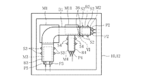
次に、各テーブル10及び12にそれぞれ設けられているブランク材Bの位置決め装置及び固定装置を図4及び図5を参照して説明する。
That is, the blank material B is composed of four members B1, B2, B3, and B4, and each butted portion is welded. By controlling the controller, the
Next, a positioning device and a fixing device for the blank material B provided in each of the tables 10 and 12 will be described with reference to FIGS.
各テーブル10及び12には、位置決め装置として、予め定められた位置に出没自在に設けられ、ブランク材Bに当接するストッパピンと、ブランク材をあらかじめ定められた方向に押圧する押圧部材が設けられている。また、固定装置として、テーブル10,12における、位置決めされたブランク材Bに対応する位置に装着され、ブランク材Bの下面を吸着するマグネットクランプM1,M11,M2,M3及びM4が設けられている。これらマグネットクランプは、磁気式であるので、ブランク材Bの下面を吸着及び非吸着を簡単に切り換えることができる
そして、この溶接加工装置においては、まずブランク材B1を位置決めした上でテーブル10,12に固定し、次いでブランク材B2、B3,B4を位置決めしてテーブル10,12に固定するように構成されている。
Each table 10 and 12 is provided with a stopper pin that comes into contact with the blank material B and a pressing member that presses the blank material in a predetermined direction as a positioning device. Yes. As the fixing device, magnet clamps M1, M11, M2, M3, and M4 that are attached to the tables 10 and 12 at positions corresponding to the positioned blank material B and attract the lower surface of the blank material B are provided. . Since these magnet clamps are magnetic, the lower surface of the blank material B can be easily switched between adsorption and non-adsorption. And in this welding processing apparatus, the blank material B1 is first positioned and then the tables 10, 12 The blank materials B2, B3, B4 are then positioned and fixed to the tables 10, 12.
このため、図4に示されるように、まずブランク材B1を位置決めするために、6つのストッパピンS1をテーブル10,12上の予め定められた位置に突出させると共に、2つの押圧部材P1によりブランク材B1をストッパピンS1に確実に当接するように図矢印の方向に押圧し、これにより同ブランク材B1の位置決めが完了する。そして、この状態で、マグネットクランプM1及びM11によりブランク材B1を吸着し、これによりブランク材B1がテーブル10,12上の予め定められた位置に固定される。その後、各ストッパピンS1及び押圧部材P1は、テーブル10,11上に突出しないように、テーブル10,11内に下降する。 For this reason, as shown in FIG. 4, first, in order to position the blank material B1, the six stopper pins S1 are projected to predetermined positions on the tables 10 and 12, and the blank is formed by the two pressing members P1. The material B1 is pressed in the direction of the arrow so as to surely abut against the stopper pin S1, thereby completing the positioning of the blank material B1. In this state, the blank material B1 is attracted by the magnet clamps M1 and M11, and thereby the blank material B1 is fixed at a predetermined position on the tables 10 and 12. Thereafter, each stopper pin S1 and the pressing member P1 are lowered into the tables 10 and 11 so as not to protrude onto the tables 10 and 11.
次いで、図5に示されるように、ブランク材B1,B2及びB3を位置決めするために、4つのストッパピンS2、4つのストッパピンS3及び4つのストッパピンS4をテーブル10,11上に突出させると共に、それぞれ2つの押圧部材P2,2つの押圧部材P3及び2つの押圧部材P4により各ブランク材B2,B3及びB4を、既にテーブル10,12上に固定されているブランク材B1に確実に当接するように図矢印の方向に押圧し、これにより各ブランク材B2,B3及びB4の位置決めが完了する。そして、この状態でマグネットクランプM2,M3及びM4により各ブランク材B2,B3及びB4を吸着し、これにより各ブランク材B2,B3及びB4がテーブル10,12上の予め定められた位置に固定される。その後、各ストッパピンS2,S3及びS4並びに各押圧部材P2,P3及びP4は、テーブル10,11上に突出しないように、テーブル10,11内に下降する。 Next, as shown in FIG. 5, in order to position the blanks B1, B2 and B3, the four stopper pins S2, the four stopper pins S3 and the four stopper pins S4 are projected on the tables 10 and 11. Each of the blank members B2, B3, and B4 is surely brought into contact with the blank member B1 that is already fixed on the tables 10 and 12 by the two pressing members P2, the two pressing members P3, and the two pressing members P4, respectively. Is pressed in the direction of the arrow, thereby completing the positioning of the blank materials B2, B3 and B4. In this state, the blank materials B2, B3, and B4 are attracted by the magnet clamps M2, M3, and M4, and thereby, the blank materials B2, B3, and B4 are fixed at predetermined positions on the tables 10 and 12, respectively. The Thereafter, the stopper pins S2, S3 and S4 and the pressing members P2, P3 and P4 are lowered into the tables 10 and 11 so as not to protrude on the tables 10 and 11.
なお、上述の各ストッパピンS2,S3及びS4は、各ストッパピンS2,S3及びS4は、各ブランク材B2,B3及びB4との間に若干の隙間が設定されており、各ブランク材B2,B3及びB4が各押圧部材P2,P3及び部材P4により押圧されたときに、倒れることを防止するガイド機能を担っている。
上述の位置決め装置は、各ブランク材B2,B3及びB4をブランク材B1に当接するように押圧したときに、一方のブランク材が他方のブランク材に乗り上げることを防止するための装置を有している。ここでは、ブランク材B1とB2と関係において設けられた装置を説明する。
Each of the stopper pins S2, S3 and S4 described above has a slight gap between each of the stopper pins S2, S3 and S4 and each of the blank materials B2, B3 and B4. When B3 and B4 are pressed by the pressing members P2, P3 and the member P4, they have a guide function for preventing them from falling.
The above-mentioned positioning device has a device for preventing one blank from riding on the other blank when each blank B2, B3 and B4 is pressed against the blank B1. Yes. Here, the apparatus provided in relation to the blank materials B1 and B2 will be described.
図5に示されるように、テーブル10,12におけるブランク材B1とブランク材B2との突き合わせ部分の両側部には、ガイド部材36が設けられている。ガイド部材36は、図6〜図8に示されるように、溝36aを有し、使用状態において、ブランク部材B1とB2との突き合わせ部の側部が溝36a内に収容されるように位置される。そして、溝36aの高さは、例えばブランク材B2がブランク材B1の上方に乗り上げようとしても、それを阻止することができるように設定されている。またガイド部材36は、非使用状態において、図6に2点鎖線38で示されるように、ブランク材B1,B2と重ならない位置にまで後退し、さらにテーブル10,12に突出しないように、テーブル10,11内に下降する。
As shown in FIG. 5, guide
以上より明らかなように、本溶接加工装置においては、ブランク材Bが固定される第1及び第2のテーブル10及び12が第1及び第2位置決めステーション4及び6と溶接ステーション2と順に交互に移動し、そして溶接ステーション2において一方のテーブル10または12上に固定されたブランク材を溶接する作業が行われているときに、位置決めステーション4または6において他方のテーブル10または12上にブランク材Bを位置決め・固定する作業が行われる。したがって、ブランク材Bの溶接と位置決めを同時に行うことができるので、全体の作業時間を短縮できる。しかも、ブランク材Bに対して同じ溶接を行う限り、溶接ステーション2は1つで足りるので、上述の従来装置に比べてスペース的に格段に有利である。しかも、第1位置決めステーション4と第2位置決めステーション6は、溶接ステーション2を挟んで反対側に配置されているので、両ステーション4及び6を溶接ステーション2と共に平面的に配置することができ、これにより装置の高さを小さく抑えることができる。
As apparent from the above, in the present welding processing apparatus, the first and second tables 10 and 12 to which the blank material B is fixed are alternately arranged in the order of the first and
また本溶接加工装置は、第1及び第2テーブル10及び12の一方が溶接ステーション2にあって、そのテーブル上のブランク材Bの溶接作業が行われる。その間、第1及び第2テーブル10及び12の他方が位置決めステーション4または6にあって、ロボット24または26が、位置決めステーション4または6に移動したテーブル10または12上の完成品Cを搬出ステーション18のターンテーブル34上に移動し、ロボット20または22が、搬入ステーション16のターンテーブル30上のブランク材Bを位置決めステーション4または6にあるテーブル10または6上に移動する。したがって、ブランク材Bの搬入及び完成品Cの搬出も含めて、全体としても作業時間を短縮することができる。
Further, in the present welding processing apparatus, one of the first and second tables 10 and 12 is in the
本溶接加工装置におけるブランク材Bのテーブル10,12に対する位置決めに及び固定に関しては、まず第1ブランク材B1を、ストッパS1及び押圧部材P1を用いて位置決めすると共に、マグネットクランプM1及びM11を用いてテーブル10,12上の予め定められた位置に固定し、さらに、第2〜第4ブランク材B2〜B4をそれぞれ押圧部材P2〜P4により押圧して同第1ブランク材B1に突き合わせ、その状態で同ブランク材B2〜B4をそれぞれマグネットクランプM2〜M4によりテーブル10,12に固定するように構成されている。したがって、第1ブランク材B1に対して第2〜第4ブランク材B2〜B4を精度良く位置決めすることができる。 Regarding positioning and fixing of the blank material B with respect to the tables 10 and 12 in the welding apparatus, first, the first blank material B1 is positioned using the stopper S1 and the pressing member P1, and the magnet clamps M1 and M11 are used. The table is fixed at a predetermined position on the tables 10 and 12, and the second to fourth blank materials B2 to B4 are pressed by the pressing members P2 to P4, respectively, to be brought into contact with the first blank material B1. The blank materials B2 to B4 are configured to be fixed to the tables 10 and 12 by magnet clamps M2 to M4, respectively. Therefore, the second to fourth blank materials B2 to B4 can be accurately positioned with respect to the first blank material B1.
しかも、各ブランク材B1〜B4は、その下面をマグネットクランプM1,M11及びM2〜M4により吸着されることによってテーブル10,11に固定されるので、各ブランク材B1〜B4の上面にクランプ等が突出しない。これにより、溶接ステーション2においてレーザ溶接を行う溶接装置14の溶接ヘッド14fの平面移動に制約がなく、同溶接ヘッド14Fの高速移動が可能となる。
Moreover, since the lower surfaces of the blank materials B1 to B4 are fixed to the tables 10 and 11 by the lower surfaces thereof being attracted by the magnet clamps M1, M11 and M2 to M4, clamps or the like are provided on the upper surfaces of the blank materials B1 to B4. Does not protrude. Thereby, there is no restriction | limiting in the plane movement of the
次に、本発明の第2の実施形態を図9〜図11に従って説明する。図9は第2の実施形態に係る溶接加工装置を示す平面図、図10は図9の溶接ステーション及び位置決めステーションの拡大図、図11は図10の右側面図である。
この実施形態に係る溶接加工装置は、溶接ステーション42と、同溶接ステーション2の一側に配置された位置決めステーション44とを備えている。これらステーション42及び44に亘ってガイド部材としての下部レール46及び上部レール48が設けられており、下部レール46上に第1テーブル50が、上部レール48には第2テーブル52が案内されている。第1テーブル50は、下部レール46に沿って位置決めステーション44と溶接ステーション42とを移動可能であり、第2テーブル52は、上部レール48に沿って第2位置決めステーション44と溶接ステーション42とを移動可能である。溶接ステーション42には、ブランク材Bを溶接する溶接装置54が設けられている。第1及び第2テーブル50及び52は、後述するが、ブランク材Bをテーブル上に位置決めし、かつ固定する機能を有している。
Next, a second embodiment of the present invention will be described with reference to FIGS. 9 is a plan view showing a welding apparatus according to the second embodiment, FIG. 10 is an enlarged view of the welding station and positioning station of FIG. 9, and FIG. 11 is a right side view of FIG.
The welding processing apparatus according to this embodiment includes a
溶接ステーション42の別の一側には、ブランク材Bを搬入する搬入ステーション56が配置され、他側には、ブランク材Bの溶接を完了した完成品を搬出する搬出ステーション58が配置されている。搬入ステーション56と位置決めステーション44との間には、搬入ステーション56上のブランク材Bを位置決めステーション44に移動する第1移動装置としてのロボット60が配置されている。また搬出ステーション58と位置決めステーション44の間には、位置決めステーション44上のブランク材Bの溶接を完了した完成品Cを搬出ステーション58に移動する第2移動装置としてのロボット62が配置されている。なお、各ロボット60及び62はそれぞれ先端にブランク材Bを吸着する吸着部60a及び62aを有している。
On another side of the
搬入ステーション56には、上面を2つに分割され、軸64を中心に回転できるターンテーブル64が設けられ、搬出ステーション58には、上面を2つに分割され、軸68を中心に回転できるターンテーブル70が設けられている。
ここで、第1及び第2テーブル50及び52と、各ロボット60及び62と、各ターンテーブル66及び70の作動を互いに関連付けて説明する。
The
Here, the operations of the first and second tables 50 and 52, the
ターンテーブル66は、図左半分の所定位置に所定数重ねられたブランク材Bが載置されると、回転し、その載置されたブランク材Bがターンテーブル66の図右半分に移動する。ターンテーブル66の左半分は空になると直ぐに次の所定数重ねられたブランク材Bが載置される。そして、ターンテーブル66の図右半分が空になると、ターンテーブル66は回転して、ターンテーブルの図右半分には常にブランク材Bが載置された状態を保たれる。
When a predetermined number of blank materials B stacked on a predetermined position in the left half of the figure are placed on the
今、第1テーブル50が空の状態で位置決めステーション44にあり、かつ第2テーブル52が空の状態で溶接ステーション42にあるとする。まず、ロボット60が、ターンテーブル66の図右半分にあるブランク材Bを吸着部60aにより吸着して、第1テーブル50上に載置する。第1テーブル50上において、ブランク材Bは予め定められた位置に位置決めされて固定された後、同第1テーブル50が下部レール46に沿って溶接ステーション42に移動する。なお、このとき、第2テーブル52は上部レール48に沿って位置決めステーション44に移動する。
Now, assume that the first table 50 is empty and is in the
次いで、溶接ステーション42において、溶接装置54により、第1テーブル50上のブランク材Bをお互いに溶接する作業が実行される。その間、ロボット60が、ターンテーブルの図右半分にあるブランク材Bを吸着部60aにより吸着して、位置決めステーション44にある第2テーブル52上に載置する。
溶接ステーション42における溶接作業が完了し、かつ位置決めステーション44におけるブランク材Bの載置が完了すると、完成品Cを載せた第1テーブル50が再び下部レール46に沿って位置決めステーション44に移動すると共に、ブランク材Bを載せた第2テーブル52が上部レール48に沿って溶接ステーション42に移動する。
Next, in the
When the welding operation at the
位置決めステーション44においては、ロボット62が、第1テーブル50上にある完成品Bを吸着部62aにより吸着して、搬出ステーション58のターンテーブル70の図左半分上に移動する。なお、完成品Cは、ターンテーブル70の図左半分に所定数重ねられると、ターンテーブル70が回転して、ターンテーブル70の図右半分に移動し、作業者あるいは他のロボットによる運び出しを待つ。さらにロボット60が、ターンテーブル66の右半分にあるブランク材Bを吸着部60aにより吸着して、第1テーブル50上に移動する。そして、第1テーブル50において、ブランク材Bが予め定められた位置に位置決めされて固定される作業が実行される。
In the
溶接ステーション42においては、溶接装置54により、第2テーブル52上のブランク材Bをお互いに溶接する作業が実行される。
そして、位置決めステーション44及び溶接ステーション42での作業が完了すると、第1テーブル50は下部レール46に沿って溶接ステーション42に移動し、第2テーブル52は上部レールに沿って位置決めステーション44に移動する。
In the
When the operations at the
位置決めステーション44においては、ロボット62が、第2テーブル52上にある完成品Cを吸着部62aにより吸着して、搬出ステーション58のターンテーブル70の図左半分上に移動する。さらにロボット60が、ターンテーブル66の右半分にあるブランク材Bを吸着部60aにより吸着して、第2テーブル52上に移動する。そして、第1テーブル50において、ブランク材Bが予め定められた位置に位置決めされて固定される作業が実行される。
In the
溶接ステーション42においては、溶接装置54により、第1テーブル10上のブランク材Bをお互いに溶接する作業が実行される。
第1及び第2テーブル50及び52と、各ロボット60及びと、各ターンテーブル66及び70は、以上のような作動を繰り返し行うものである。
次に、溶接ステーション42における溶接装置54を、図10及び図11を参照して説明する。
In the
The first and second tables 50 and 52, the
Next, the
溶接装置54は、溶接ステーション2の両側部にレール8と平行に延びた2つのレール54aと、同レール54aにそれぞれ案内される2つのポスト54bと、同2つのポスト54b間に橋設され、レール54aと直交するように延び、かつ同ポスト54bに沿って上下動可能なレール54cと、同レール54cに案内されるスライダ54dと、同スライダ54dに支持部材54eを介して支持された溶接ヘッド54fを有している。そして、ポスト54bのレール14aに対する位置と、レール54cのポスト54bに対する位置と、スライダ54dのレール54cに対する位置は、図示しないコントローラにより、溶接位置に応じて制御されている。
The
つまり、ブランク材Bは、4つの部材B1,B2,B3及びB4から成り、各突き合わせ部を溶接されるが、前記コントローラを制御することによって、溶接ヘッド54fを、溶接が必要な各突き合わせ部に沿って移動させることができる。特に溶接ステーション42において、第1テーブル50と第2テーブル52は、互いに異なる高さにあるが、溶接ヘッド54fが上下にも移動できるので、必要な溶接作業を行うことができる。
That is, the blank material B is composed of four members B1, B2, B3, and B4, and each butt portion is welded. By controlling the controller, the
なお、第1テーブル50及び第2テーブル52は、それぞれブランク材Bの位置決め装置及び固定装置を有しているが、その構造及び作用は、上述の第1実施形態における第1テーブル10及び第2テーブル12にそれぞれ設けられているものと、同じものが設けられている。
以上より明らかなように、この第2の実施形態に係る溶接加工装置において、ブランク材Bが固定される第1及び第2のテーブル50及び52が位置決めステーション44と溶接ステーション42とを交互に移動し、そして溶接ステーション42において一方のテーブル50または52上に固定されたブランク材Bを溶接する作業が行われているときに、位置決めステーション44において他方のテーブル10または12上にブランク材Bを位置決め・固定する作業が行われる。したがって、第1実施形態の場合と同様に、ブランク材Bの溶接と位置決めを同時に行うことができるので、全体の作業時間を短縮できる。しかも、ブランク材Bに対して同じ溶接を行う限り、溶接ステーション2は1つで足りるので、従来装置に比べてスペース的に格段に有利である。しかも、第1テーブル50と第2テーブル52が異なる高さを移動するように構成されているので、1つの位置決めステーション44で足りるので、第1の実施形態の溶接加工装置よりも、平面視における装置全体をコンパクトにすることができる。
The first table 50 and the second table 52 have a positioning device and a fixing device for the blank material B, respectively, but the structure and operation thereof are the first table 10 and the second table in the first embodiment described above. The same ones as those provided on the table 12 are provided.
As is clear from the above, in the welding processing apparatus according to the second embodiment, the first and second tables 50 and 52 to which the blank material B is fixed are moved alternately between the
また本溶接加工装置において、第1及び第2テーブル50及び52の一方が溶接ステーション42にあって、そのテーブル上のブランク材Bの溶接作業が行われる。その間、第1及び第2テーブル50及び52の他方が位置決めステーション44にあって、ロボット62が、位置決めステーション4または6に移動したテーブル10または12上の完成品Bを搬出ステーション18のターンテーブル34上に移動し、さらにロボット60が、搬入ステーション56のターンテーブル66上のブランク材Bを位置決めステーション44にあるテーブル50または52上に移動する。したがって、第1実施形態の場合と同様に、ブランク材Bの搬入及び完成品Cの搬出も含めて、全体としても作業時間を短縮することができる。なお、本溶接加工装置は、第1実施形態と比べて、位置決めステーションの数が少ないので、ブランク材Bまたは完成品Cを移動するロボットの必要な作動面積が小さいので、ロボットの数を減らすことができる。
Moreover, in this welding processing apparatus, one of the first and second tables 50 and 52 is in the
溶接加工装置におけるブランク材Bのテーブル50,52に対する位置決めに及び固定に関しては、第1の実施形態のものと同じ作用効果を奏するものである。
以上で、本発明の実施形態の説明を終えるが、本発明は上述した実施形態に限定されるものではない。
上述した各実施形態において、溶接装置14または54は、いずれも溶接ヘッド14fまたは54fが、レール8または48と平行に延びたレール14aまたは54aに沿って移動されるように構成されているが、代わりに溶接ステーション2または42において、溶接されるブランク材が載置されたテーブル10,12または50,52を、レール8または48に沿って移動させるように構成することも可能である。ガイド部材36に関しても、例えばブランク材の突き合わせ部分を上方から押さえ込むようなブロック体をテーブル10,12に設けることが可能である。
Regarding the positioning and fixing of the blank material B with respect to the tables 50 and 52 in the welding apparatus, the same operational effects as those of the first embodiment are exhibited.
This is the end of the description of the embodiment of the present invention, but the present invention is not limited to the above-described embodiment.
In each of the embodiments described above, the
2 溶接ステーション
4 第1位置決めステーション
6 第2位置決めステーション
8 第1テーブル
10 第2テーブル
14 溶接装置
16 搬入ステーション
18 搬出ステーション
42 溶接ステーション
44 位置決めステーション
50 第1テーブル
52 第2テーブル
54 溶接装置
56 搬入ステーション
58 搬出ステーション
DESCRIPTION OF
Claims (4)
前記ブランク材を相互に溶接する溶接ヘッドを有する溶接ステーションと、
前記溶接ステーションの一側に配置された第1位置決めステーションと、
前記溶接ステーションの他側に配置された第2位置決めステーションと、
前記複数のブランク材を同テーブルの予め定められた位置に固定する固定装置を有すると共に、前記位置決めステーションと前記溶接ステーションとに移動可能な第1及び第2テーブルと、
前記第1テーブル及び第2テーブル上の予め定められた位置に突出可能なストッパ、及び当該各テーブル上の前記ブランク材が前記ストッパに当接するように同ブランク材を押圧する押圧部材を有する位置決め装置と、
溶接前の前記複数のブランク材が載置される搬入ステーションと、
前記複数のブランク材が溶接された完成品が載置される搬出ステーションと、
前記搬入ステーション上のブランク材を、前記位置決めステーションにある前記第1テーブルまたは第2テーブルの上に移動する第1移動装置と、
前記溶接ステーションで溶接が完了した後に、前記位置決めステーションに移動した前記第1テーブルまたは第2テーブル上の完成品を、前記搬出ステーションに移動する第2移動装置と、を備え、
前記第1テーブルが前記第1位置決めステーションに移動されたときに前記第2テーブルが前記溶接ステーションに移動され、前記第1テーブルが前記溶接ステーションに移動されたときに前記第2テーブルが前記第2位置決めステーションに移動されるように構成され、
前記第1テーブルまたは第2テーブルが対応する前記位置決めステーションに移動したときに、前記第1ブランク材を前記位置決め装置により予め定められた位置に配置し、次いで同第1ブランク材を前記固定装置により同テーブルに固定し、さらに同第1ブランク材に第2ブランク材を突き合わせるべく押圧させた状態で同第2ブランク材を前記固定装置により同テーブルに固定させ、同テーブルと共に前記溶接ステーションに移動させ、前記溶接ヘッドにより互いに溶接されるように構成されたことを特徴とする溶接加工装置。 A welding apparatus for welding a plurality of blank materials including at least a first blank material and a second blank material to each other,
A welding station having a welding head for welding the blanks to each other;
A first positioning station disposed on one side of the welding station;
A second positioning station disposed on the other side of the welding station;
A first and a second table having a fixing device for fixing the plurality of blank materials to a predetermined position of the table, and movable to the positioning station and the welding station;
A positioning device having a stopper that can project to a predetermined position on the first table and the second table, and a pressing member that presses the blank material so that the blank material on each table contacts the stopper. When,
A loading station on which the plurality of blank materials before welding are placed;
An unloading station on which the finished product, on which the plurality of blank materials are welded, is placed;
A first moving device for moving the blank material on the carry-in station onto the first table or the second table in the positioning station;
A second moving device that moves the finished product on the first table or the second table moved to the positioning station after welding is completed at the welding station to the unloading station ;
The second table is moved to the welding station when the first table is moved to the first positioning station, and the second table is moved to the second position when the first table is moved to the welding station. is configured so that is moved to the positioning station,
When said first table or the second tables is moved to the positioning station corresponding, the first blank is arranged at the predetermined position by the positioning device, then the fixing device of the same first blank The second blank material is fixed to the table by the fixing device in a state where the second blank material is pressed against the first blank material to be abutted with the first blank material. the moved, welding apparatus characterized by being configured to be welded together by the welding head.
Priority Applications (6)
| Application Number | Priority Date | Filing Date | Title |
|---|---|---|---|
| JP2008219712A JP5212632B2 (en) | 2008-08-28 | 2008-08-28 | Welding equipment |
| EP09809945A EP2335864A4 (en) | 2008-08-28 | 2009-08-26 | Welding device |
| PCT/JP2009/064864 WO2010024294A1 (en) | 2008-08-28 | 2009-08-26 | Welding device |
| RU2011111428/02A RU2479399C2 (en) | 2008-08-28 | 2009-08-26 | Welding equipment |
| CN200980142380XA CN102196882A (en) | 2008-08-28 | 2009-08-26 | Welding device |
| US13/060,953 US20110147436A1 (en) | 2008-08-28 | 2009-08-26 | Welding equipment |
Applications Claiming Priority (1)
| Application Number | Priority Date | Filing Date | Title |
|---|---|---|---|
| JP2008219712A JP5212632B2 (en) | 2008-08-28 | 2008-08-28 | Welding equipment |
Publications (2)
| Publication Number | Publication Date |
|---|---|
| JP2010052008A JP2010052008A (en) | 2010-03-11 |
| JP5212632B2 true JP5212632B2 (en) | 2013-06-19 |
Family
ID=41721461
Family Applications (1)
| Application Number | Title | Priority Date | Filing Date |
|---|---|---|---|
| JP2008219712A Expired - Fee Related JP5212632B2 (en) | 2008-08-28 | 2008-08-28 | Welding equipment |
Country Status (6)
| Country | Link |
|---|---|
| US (1) | US20110147436A1 (en) |
| EP (1) | EP2335864A4 (en) |
| JP (1) | JP5212632B2 (en) |
| CN (1) | CN102196882A (en) |
| RU (1) | RU2479399C2 (en) |
| WO (1) | WO2010024294A1 (en) |
Families Citing this family (9)
| Publication number | Priority date | Publication date | Assignee | Title |
|---|---|---|---|---|
| DE102009049892B3 (en) * | 2009-10-20 | 2011-01-05 | Emag Holding Gmbh | Device for connecting a workpiece with a joining part using laser radiation, where the workpiece and the joining part are connected along a given joining line by a welding seam, comprises a workpiece carrier movable along a guide web |
| JP5645595B2 (en) * | 2010-10-25 | 2014-12-24 | 株式会社アマダ | Laser processing apparatus and laser processing method |
| US8434657B2 (en) | 2011-06-09 | 2013-05-07 | Landoll Corporation | Gantry-based welding system and method |
| US8210418B1 (en) * | 2011-06-09 | 2012-07-03 | Landoll Corporation | Multi-station, gantry-based automated welding system |
| CN103600170B (en) | 2013-04-28 | 2015-08-26 | 宝山钢铁股份有限公司 | A kind of longitudinal metal plate loading and unloading and cutting method and system thereof |
| CN105364315A (en) * | 2014-08-19 | 2016-03-02 | 深圳市普尔信通讯设备有限公司 | Automatic laser machine |
| CN105292988A (en) * | 2015-11-26 | 2016-02-03 | 重庆贝华科技有限公司 | Air conditioner outdoor unit welding production system |
| CN107283108B (en) * | 2017-07-22 | 2019-01-11 | 合肥亚美科技股份有限公司 | A kind of aerial working platform chassis joint welding mould |
| CN113732607B (en) * | 2021-09-28 | 2023-10-10 | 九江职院船舶与海洋工程技术有限公司 | Ship thick plate welding, fixing and clamping device |
Family Cites Families (12)
| Publication number | Priority date | Publication date | Assignee | Title |
|---|---|---|---|---|
| SU751546A1 (en) * | 1977-10-24 | 1980-07-30 | Предприятие П/Я Г-4365 | Producing line for assembling and welding metallic articles |
| IT1249917B (en) * | 1991-06-14 | 1995-03-30 | Prima Ind Spa | UNIT FOR CUTTING AND / OR LASER WELDING. |
| FR2698575B1 (en) * | 1992-11-30 | 1995-03-17 | Lorraine Laminage | Device for positioning sheet blanks in a continuous edge-to-edge welding installation of these sheet blanks. |
| US5630269A (en) * | 1995-06-19 | 1997-05-20 | General Motors Corporation | Method for fixturing abutted sheet metal parts for welding |
| JP3516575B2 (en) * | 1997-08-29 | 2004-04-05 | 株式会社日平トヤマ | Laser processing equipment |
| JP4028922B2 (en) * | 1997-12-08 | 2008-01-09 | 株式会社アマダ | Laser processing machine |
| JP3419318B2 (en) * | 1998-09-03 | 2003-06-23 | オムロン株式会社 | Automatic processing equipment |
| JP4445633B2 (en) * | 2000-02-28 | 2010-04-07 | 菊池プレス工業株式会社 | Seam welding method and apparatus |
| RU2221683C1 (en) * | 2002-09-16 | 2004-01-20 | Открытое акционерное общество "ГАЗ" | Robotized complex for welding subassemblies of automobile body |
| FR2869558B1 (en) * | 2004-04-29 | 2006-09-01 | Vai Clecim Soc Par Actions Sim | METHOD FOR ADJUSTING THE SOLDER CORD THICKNESS OF TWO METAL SHEETS |
| WO2006131957A1 (en) * | 2005-06-06 | 2006-12-14 | Ihi Corporation | Method and device for positioning butt welding plate material |
| US8113415B2 (en) * | 2007-06-07 | 2012-02-14 | Doben Limited | Modular welding fixture |
-
2008
- 2008-08-28 JP JP2008219712A patent/JP5212632B2/en not_active Expired - Fee Related
-
2009
- 2009-08-26 CN CN200980142380XA patent/CN102196882A/en active Pending
- 2009-08-26 RU RU2011111428/02A patent/RU2479399C2/en not_active IP Right Cessation
- 2009-08-26 WO PCT/JP2009/064864 patent/WO2010024294A1/en active Application Filing
- 2009-08-26 US US13/060,953 patent/US20110147436A1/en not_active Abandoned
- 2009-08-26 EP EP09809945A patent/EP2335864A4/en not_active Withdrawn
Also Published As
| Publication number | Publication date |
|---|---|
| WO2010024294A1 (en) | 2010-03-04 |
| EP2335864A1 (en) | 2011-06-22 |
| CN102196882A (en) | 2011-09-21 |
| RU2011111428A (en) | 2012-10-10 |
| US20110147436A1 (en) | 2011-06-23 |
| EP2335864A4 (en) | 2012-07-04 |
| RU2479399C2 (en) | 2013-04-20 |
| JP2010052008A (en) | 2010-03-11 |
Similar Documents
| Publication | Publication Date | Title |
|---|---|---|
| JP5212632B2 (en) | Welding equipment | |
| KR20110084327A (en) | Welding apparatus and method of welding using the apparatus | |
| JP5196169B2 (en) | Workpiece processing equipment | |
| JP3074930B2 (en) | Welding panel manufacturing equipment capable of manufacturing two or more types | |
| JP5077576B2 (en) | Processing equipment | |
| WO2013118438A1 (en) | Machining system, workpiece machining method, and control method | |
| JP2007319874A (en) | Workpiece positioning apparatus | |
| KR20210066759A (en) | Wafer dividing device, inverting device, and transfer system | |
| JP5196170B2 (en) | Welding apparatus and welding method | |
| JP2017170551A (en) | Full automatic drill device | |
| JP2007160375A (en) | Workpiece transporting apparatus for laser beam machine | |
| JP5152498B2 (en) | Work positioning apparatus and method and work positioning apparatus for butt welding | |
| JP3558988B2 (en) | Welding method and welding system | |
| JP4946503B2 (en) | Work picking device | |
| JP2008133115A (en) | Workpiece take-out method and workpiece take-out device | |
| JP5024025B2 (en) | Board material unloading equipment | |
| JP2008207888A (en) | Workpiece loading method | |
| JP4923752B2 (en) | Board processing system | |
| JP5346681B2 (en) | Member assembly apparatus and member assembly method | |
| JP5196173B2 (en) | Welding equipment | |
| JP5778792B2 (en) | Machining system and control method | |
| JPH10167473A (en) | Article stacking device and its method | |
| JP2920992B2 (en) | Welding equipment | |
| JP2003305579A (en) | Laser beam welding device and welding method thereof | |
| JPH10180675A (en) | Workpiece pickup device |
Legal Events
| Date | Code | Title | Description |
|---|---|---|---|
| A621 | Written request for application examination |
Free format text: JAPANESE INTERMEDIATE CODE: A621 Effective date: 20110627 |
|
| A131 | Notification of reasons for refusal |
Free format text: JAPANESE INTERMEDIATE CODE: A131 Effective date: 20121031 |
|
| A521 | Written amendment |
Free format text: JAPANESE INTERMEDIATE CODE: A523 Effective date: 20121221 |
|
| TRDD | Decision of grant or rejection written | ||
| A01 | Written decision to grant a patent or to grant a registration (utility model) |
Free format text: JAPANESE INTERMEDIATE CODE: A01 Effective date: 20130130 |
|
| A61 | First payment of annual fees (during grant procedure) |
Free format text: JAPANESE INTERMEDIATE CODE: A61 Effective date: 20130212 |
|
| FPAY | Renewal fee payment (event date is renewal date of database) |
Free format text: PAYMENT UNTIL: 20160308 Year of fee payment: 3 |
|
| LAPS | Cancellation because of no payment of annual fees |