JP5207796B2 - Flame resistant treatment apparatus and precursor fiber bundle flame resistant treatment method - Google Patents
Flame resistant treatment apparatus and precursor fiber bundle flame resistant treatment method Download PDFInfo
- Publication number
- JP5207796B2 JP5207796B2 JP2008088610A JP2008088610A JP5207796B2 JP 5207796 B2 JP5207796 B2 JP 5207796B2 JP 2008088610 A JP2008088610 A JP 2008088610A JP 2008088610 A JP2008088610 A JP 2008088610A JP 5207796 B2 JP5207796 B2 JP 5207796B2
- Authority
- JP
- Japan
- Prior art keywords
- flameproofing
- hot air
- fiber bundle
- precursor fiber
- heat treatment
- Prior art date
- Legal status (The legal status is an assumption and is not a legal conclusion. Google has not performed a legal analysis and makes no representation as to the accuracy of the status listed.)
- Expired - Fee Related
Links
- 239000000835 fiber Substances 0.000 title claims description 177
- 239000002243 precursor Substances 0.000 title claims description 174
- 238000000034 method Methods 0.000 title claims description 55
- 238000010438 heat treatment Methods 0.000 claims description 128
- 238000007254 oxidation reaction Methods 0.000 claims description 14
- 238000003780 insertion Methods 0.000 description 30
- 230000037431 insertion Effects 0.000 description 30
- 238000007664 blowing Methods 0.000 description 9
- 229920002239 polyacrylonitrile Polymers 0.000 description 5
- 238000009826 distribution Methods 0.000 description 4
- 230000020169 heat generation Effects 0.000 description 4
- 238000007789 sealing Methods 0.000 description 4
- 230000000052 comparative effect Effects 0.000 description 3
- 229920000049 Carbon (fiber) Polymers 0.000 description 2
- XEEYBQQBJWHFJM-UHFFFAOYSA-N Iron Chemical compound [Fe] XEEYBQQBJWHFJM-UHFFFAOYSA-N 0.000 description 2
- 239000004917 carbon fiber Substances 0.000 description 2
- 238000001816 cooling Methods 0.000 description 2
- 230000007423 decrease Effects 0.000 description 2
- 239000011810 insulating material Substances 0.000 description 2
- 239000002184 metal Substances 0.000 description 2
- 229910052751 metal Inorganic materials 0.000 description 2
- VNWKTOKETHGBQD-UHFFFAOYSA-N methane Chemical compound C VNWKTOKETHGBQD-UHFFFAOYSA-N 0.000 description 2
- 238000004080 punching Methods 0.000 description 2
- 230000005855 radiation Effects 0.000 description 2
- 238000004904 shortening Methods 0.000 description 2
- 229920000297 Rayon Polymers 0.000 description 1
- 238000005520 cutting process Methods 0.000 description 1
- 238000007599 discharging Methods 0.000 description 1
- 230000000694 effects Effects 0.000 description 1
- 230000017525 heat dissipation Effects 0.000 description 1
- 238000009434 installation Methods 0.000 description 1
- 229910052742 iron Inorganic materials 0.000 description 1
- 239000000463 material Substances 0.000 description 1
- 239000002964 rayon Substances 0.000 description 1
- 229910001220 stainless steel Inorganic materials 0.000 description 1
- 239000010935 stainless steel Substances 0.000 description 1
- 239000000126 substance Substances 0.000 description 1
- 239000002699 waste material Substances 0.000 description 1
Images


Description
本発明は、耐炎化処理装置および前駆体繊維束の耐炎化処理方法に関する。 The present invention relates to a flameproofing apparatus and a flameproofing method for precursor fiber bundles.
ポリアクリロニトリル系前駆体繊維束から炭素繊維束を製造する場合など、前駆体繊維束を耐炎化処理することは広く行われている。前駆体繊維束の耐炎化処理は、前駆体繊維束を例えば200〜300℃で加熱することにより行われる。この耐炎化処理では、処理中の前駆体繊維束の発熱が著しくなると、前駆体繊維束に糸切れが生じてしまうことがある。一方、前駆体繊維束の発熱による糸切れは、耐炎化処理が進むにつれて起こり難くなる傾向がある。そのため、前駆体繊維束の耐炎化処理では、一度に高温で加熱して処理せずに、加熱と冷却とを交互に複数回繰り返し、徐々に加熱温度を上昇させて処理する方法が採用されている。 For example, when a carbon fiber bundle is produced from a polyacrylonitrile-based precursor fiber bundle, the precursor fiber bundle is subjected to flame resistance treatment. The flameproofing treatment of the precursor fiber bundle is performed by heating the precursor fiber bundle at, for example, 200 to 300 ° C. In this flameproofing treatment, if the heat generation of the precursor fiber bundle being processed becomes significant, yarn breakage may occur in the precursor fiber bundle. On the other hand, yarn breakage due to heat generation of the precursor fiber bundle tends to be less likely to occur as the flameproofing process proceeds. Therefore, in the flameproofing treatment of the precursor fiber bundle, a method in which heating and cooling are alternately repeated a plurality of times without being heated at a high temperature at a time, and the heating temperature is gradually increased to be processed. Yes.
このような耐炎化処理装置の具体例としては、図5に示すように、前駆体繊維束Wを耐炎化処理する熱処理室110と、熱処理室110の外側で前駆体繊維束Wを折り返して、前駆体繊維束Wを多段に熱処理室110内に走行させるローラ115群と、熱処理室110内に一定の間隔で配置され、前駆体繊維束Wの走行方向に沿って熱風を当てて加熱する熱風供給ノズル116および熱風吸込ノズル118とを具備する耐炎化処理装置101がある(特許文献1)。
耐炎化処理装置101では、前駆体繊維束Wを熱処理室110内に多段に走行させ、加熱と冷却を繰り返すため、前駆体繊維束Wの発熱による糸切れを抑えられる。また、このような耐炎化処理装置101を複数備え、各熱処理室110の熱風の温度を例えば230℃、240℃、250℃のように設定することで、前駆体繊維束Wを連続的に耐炎化処理できる。
As a specific example of such a flameproofing apparatus, as shown in FIG. 5, the precursor fiber bundle W is folded outside the
In the
しかし、耐炎化処理装置101では、前駆体繊維束Wの糸切れのおそれが耐炎化処理の初期において最も高いことから、熱処理室110内に吹き込む熱風の温度を、熱処理室110に最初に供給される前駆体繊維束Wに糸切れが生じない温度に設定する必要があった。そのため、非常に多段階の温度領域が必要となり、前駆体繊維束の耐炎化処理には長時間を要していた。
However, in the
そこで、前駆体繊維束の耐炎化処理に要する時間を短縮する方法として、複数備えた耐炎化処理装置101において、各熱処理室110における前駆体繊維束Wの供給速度(走行速度)を変化させ、耐炎化処理の加熱時間を調整する方法が示されている(特許文献2)。
しかし、特許文献2の方法では、耐炎化処理に要する時間が短縮できるものの、各耐炎化処理装置で供給速度を変化させるため、前駆体繊維束の耐炎化処理を連続的に行うことができなかった。
そのため、前駆体繊維束を連続的に、かつ短い時間で耐炎化処理することができる耐炎化処理装置および耐炎化処理方法が求められている。
However, in the method of Patent Document 2, although the time required for the flameproofing treatment can be shortened, the supply speed is changed in each flameproofing treatment apparatus, and therefore the precursor fiber bundle cannot be flameproofed continuously. It was.
Therefore, a flameproof treatment apparatus and a flameproof treatment method capable of flameproofing a precursor fiber bundle continuously and in a short time are required.
そこで本発明では、前駆体繊維束を連続的に耐炎化処理することができ、かつ耐炎化処理に要する時間を短縮できる耐炎化処理装置を目的とする。
また、本発明では、連続的に、かつ短い時間で前駆体繊維束を耐炎化処理することのできる前駆体繊維束の耐炎化処理方法を目的とする。
Therefore, an object of the present invention is to provide a flameproofing apparatus that can continuously flameproof the precursor fiber bundle and can reduce the time required for the flameproofing process.
Another object of the present invention is to provide a flameproofing method for a precursor fiber bundle that can flameproof the precursor fiber bundle continuously and in a short time.
本発明の耐炎化処理装置は、前駆体繊維束を耐炎化処理する熱処理室と、前記熱処理室の外側で前記前駆体繊維束を(n−1)回(ただし、nは1以上の整数である。)折り返して、n段の前駆体繊維束を熱処理室内に走行させるローラ群と、前記熱処理室内を走行する前記前駆体繊維束によって仕切られる、前記熱処理室内の(n+1)段の耐炎化処理領域に、対向して設けられた熱風吹込口および熱風吸込口とを具備しており、(i+1)段目(ただし、iは耐炎化処理の順番であり、1〜nの整数である。)の耐炎化処理領域における熱風吹込口と熱風吸込口との間隔が、i段目の耐炎化処理領域における熱風吹込口と熱風吸込口との間隔と同じかまたは長くされ、かつ(n+1)段目の耐炎化処理領域における熱風吹込口と熱風吸込口との間隔が、1段目の耐炎化処理領域における熱風吹込口と熱風吸込口との間隔よりも長くされていることを特徴とする装置である。 The flameproofing apparatus of the present invention includes a heat treatment chamber for flameproofing a precursor fiber bundle, and the precursor fiber bundle is (n-1) times outside the heat treatment chamber (where n is an integer of 1 or more). There is a (n + 1) -stage flameproofing treatment in the heat treatment chamber, which is partitioned by a group of rollers that are folded to run the n-stage precursor fiber bundle in the heat treatment chamber and the precursor fiber bundle that runs in the heat treatment chamber. The region is provided with a hot air inlet and a hot air inlet provided to face each other, and (i + 1) stage (where i is the order of flameproofing treatment and is an integer of 1 to n). The interval between the hot air inlet and the hot air inlet in the flameproofing region is the same as or longer than the interval between the hot air inlet and the hot air inlet in the i-th flameproofing region, and the (n + 1) th stage Hot air inlet and hot air suction in the flameproofing region Distance between is a device which is characterized in that it is longer than the distance between the hot air Komiguchi hot air inlet in the oxidization processing region of the first stage.
また、本発明の耐炎化処理装置は、前記(n+1)段目の耐炎化処理領域における熱風吹込口と熱風吸込口との間隔が、1段目の耐炎化処理領域における熱風吹込口と熱風吸込口との間隔の1.2〜2倍であることが好ましい。 In the flameproofing apparatus of the present invention, the distance between the hot air inlet and the hot air inlet in the (n + 1) th flameproofing area is such that the hot air inlet and the hot air inlet in the first stage flameproofing area. It is preferably 1.2 to 2 times the distance from the mouth.
また、本発明の前駆体繊維束の耐炎化処理方法は、前駆体繊維束を耐炎化処理する熱処理室の外側で、前記前駆体繊維束を(n−1)回(ただし、nは1以上の整数である。)折り返して、n段の前駆体繊維束を熱処理室内に走行させ、前記熱処理室内を走行する前記前駆体繊維束によって仕切られる、前記熱処理室内の(n+1)段の耐炎化処理領域で、前記前駆体繊維束にその走行方向に沿って熱風を当てて耐炎化処理する方法において、(i+1)段目(ただし、iは耐炎化処理の順番であり、1〜nの整数である。)の耐炎化処理領域を走行する前駆体繊維束の走行方向に沿って熱風が当たる長さが、i段目の耐炎化処理領域を走行する前駆体繊維束の走行方向に沿って熱風が当たる長さと同じかまたは長くされ、かつ(n+1)段目の耐炎化処理領域を走行する前駆体繊維束の走行方向に沿って熱風が当たる長さが、1段目の耐炎化処理領域を走行する前駆体繊維束の走行方向に沿って熱風が当たる長さよりも長くされていることを特徴とする方法である。 The precursor fiber bundle according to the present invention has a flameproofing method, wherein the precursor fiber bundle is placed (n-1) times (where n is 1 or more) outside the heat treatment chamber for flameproofing the precursor fiber bundle. The n-stage precursor fiber bundle is turned into a heat treatment chamber and is divided by the precursor fiber bundle running in the heat treatment chamber, and (n + 1) -stage flameproofing treatment in the heat treatment chamber is performed. In the region, the precursor fiber bundle is subjected to a flameproofing treatment by applying hot air along the traveling direction thereof , (i + 1) stage (where i is the order of the flameproofing treatment, and is an integer of 1 to n) there.) running along the direction length impinging hot air of the precursor fiber bundle traveling flame treatment region, hot air along the running direction of the precursor fiber bundle traveling flame treatment region of the i-th stage same or lengthened, and (n + 1) stage and length hits The length of the hot air hits along the running direction of the precursor fiber bundle traveling flame treatment area, length hits the hot air along the running direction of the precursor fiber bundle which runs oxidization processing area of the first stage It is a method characterized by being made longer than this.
また、本発明の前駆体繊維束の耐炎化処理方法は、前記(n+1)段目の耐炎化処理領域を走行する前駆体繊維束の走行方向に沿って熱風が当たる長さが、1段目の耐炎化処理領域を走行する前駆体繊維束の走行方向に沿って熱風が当たる長さの1.2〜2倍であることが好ましい。
Further, in the method for flameproofing a precursor fiber bundle according to the present invention, the length that the hot air hits along the traveling direction of the precursor fiber bundle traveling in the (n + 1) th flameproofing region is the first stage. It is preferable that the length is 1.2 to 2 times as long as the hot air hits along the traveling direction of the precursor fiber bundle traveling in the flameproofing treatment region.
本発明の耐炎化処理装置は、前駆体繊維束を連続的に耐炎化処理することが、耐炎化処理に要する時間を短縮できる。
また、本発明の耐炎化処理方法によれば、連続的に、かつ短い時間で前駆体繊維束を耐炎化処理することができる。
In the flameproofing apparatus of the present invention, continuous flameproofing of the precursor fiber bundle can shorten the time required for the flameproofing process.
Further, according to the flameproofing treatment method of the present invention, the precursor fiber bundle can be flameproofed continuously and in a short time.
[耐炎化処理装置]
本発明の耐炎化処理装置は、前駆体繊維束を耐炎化処理する熱処理室と、前記熱処理室の外側で前記前駆体繊維束を(n−1)回(nは1以上の整数である)折り返して、n段の前駆体繊維束を熱処理室内に走行させるローラ群と、前記熱処理室内を走行する前記前駆体繊維束によって仕切られる、前記熱処理室内の(n+1)段の耐炎化処理領域に、対向して設けられた熱風吹込口および熱風吸込口とを具備する装置である。
また、(i+1)段目(iは1〜nの整数である)の耐炎化処理領域における熱風吹込口と熱風吸込口との間隔が、i段目の耐炎化処理領域における熱風吹込口と熱風吸込口との間隔と同じかまたは長くされ、かつ(n+1)段目の耐炎化処理領域における熱風吹込口と熱風吸込口との間隔が、1段目の耐炎化処理領域における熱風吹込口と熱風吸込口との間隔よりも長くされていることを特徴する。
[Flame resistant treatment equipment]
The flameproofing apparatus of the present invention includes a heat treatment chamber for flameproofing a precursor fiber bundle, and the precursor fiber bundle (n-1) times outside the heat treatment chamber (n is an integer of 1 or more). Folded, a (n + 1) -stage flameproofing treatment region in the heat treatment chamber, which is partitioned by a group of rollers that run the n-stage precursor fiber bundle in the heat treatment chamber and the precursor fiber bundle that runs in the heat treatment chamber, It is an apparatus comprising a hot air inlet and a hot air inlet provided to face each other.
Further, the distance between the hot air inlet and the hot air inlet in the (i + 1) -th stage (i is an integer of 1 to n) is such that the hot-air inlet and the hot air in the i-th flame-resistant area are The distance between the hot air inlet and the hot air inlet in the (n + 1) stage flameproofing region is the same as or longer than the interval between the inlet and the hot air inlet and hot air in the first flameproofing region. It is characterized by being longer than the interval with the suction port.
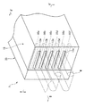
以下、本発明の耐炎化処理装置の実施形態の一例について、図1〜3に基づいて詳細に説明する。本実施形態の耐炎化処理装置1は、nが5の実施形態例である。
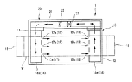
本実施形態の耐炎化処理装置1は、図1〜3に示すように、前駆体繊維束Wを耐炎化処理する熱処理室10と、熱処理室10の外側で前駆体繊維束Wを4回折り返して、5段の前駆体繊維束Wを熱処理室内に走行させるガイドローラ15(ローラー群)と、熱処理室10内を走行する前駆体繊維束Wによって仕切られる、熱処理室10内の6段の耐炎化処理領域に、対向して設けられた熱風供給ノズル16a、16b、16c、16d、16e、16f(以下、まとめて熱風供給ノズル16ということもある)および熱風吸込ノズル18a、18b、18c、18d、18e、18f(以下、まとめて熱風吸込口18ということもある)と、熱風吸込ノズル18からの熱風を加熱して熱風供給ノズル16に供給する熱風循環流路21を有する熱風循環室20とを具備している。
Hereinafter, an example of an embodiment of a flameproofing apparatus of the present invention will be described in detail based on FIGS. The
As shown in FIGS. 1 to 3, the
熱処理室10は、箱型であり、前駆体繊維束Wの供給側である前壁11に、上部から順に5段の挿入口(一端挿入口)12a、12b、12c、12d、12eが形成されている。各挿入口12a〜12eは、矩形のスリット状に形成されており、そのうち最上段の挿入口12aは、前駆体繊維束Wが供給源(図示せず)から供給される供給端となる。また、各挿入口12a〜12eの外側にはシールカーテンなどシール装置が配置される(図示せず)。
熱処理室10の材質としては、例えば、鉄、ステンレスなどが挙げられる。
The
Examples of the material of the
また、熱処理室10の前駆体繊維束Wの排出側である後壁13には、前壁11と同様に上部から順に5段の挿入口(他端挿入口)14a、14b、14c、14d、14eが形成されている(図3参照)。後壁13に形成された各挿入口14a〜14eのうち、最下段の挿入口14eは前駆体繊維束Wの排出端となっている。また、各挿入口14a〜14eの外側にはシールカーテンなどシール装置が配置される(図示せず)。前壁11側の各挿入口12a〜12eと後壁13側の各挿入口14a〜14eとは、熱処理室10の高さ方向に各々対向した位置に設けられている。
Further, the
ガイドローラ15は、熱処理室10の各挿入口12a〜12e、14a〜14eの外側に、回転可能に4つ設けられている。ガイドローラ15は、前駆体繊維束Wを掛け回して折り返すことにより、前駆体繊維束Wの走行方向を逆方向に転換させ、隣接する1つ下の挿入口に導く。
Four
本実施形態の耐炎化処理装置1では、ガイドローラ15により前駆体繊維束Wが4回折り返され、熱処理室10内を5回走行する。これにより、熱処理室10内が6段の耐炎化処理領域に仕切られる。本発明においては、熱処理室10内の各耐炎化処理領域を、耐炎化処理の順に従って、1段目〜(i+1)段目(本実施形態ではiは1〜nの整数である。本実施形態ではiは1〜5の整数である。)の耐炎化処理領域とする。
すなわち、本実施形態では、最上段の耐炎化処理領域が1段目の耐炎化処理領域であり、最下段の耐炎化処理領域が6段目の耐炎化処理領域である。前駆体繊維束Wを熱処理室10の下部側から供給し、4回折り返して5段の前駆体繊維束Wを熱処理室10内に走行させ、熱処理室10の上部側から前駆体繊維束Wを排出する場合は、最下段の耐炎化処理領域が1段目の耐炎化処理領域、最上段の耐炎化処理領域が6段目の耐炎化処理領域となる。
In the
That is, in the present embodiment, the uppermost flameproofing region is the first flameproofing region, and the lowermost flameproofing region is the sixth flameproofing region. The precursor fiber bundle W is supplied from the lower side of the
熱風供給ノズル16は、熱処理室10内に熱風を吹き込むノズルである。熱風供給ノズル16は、角筒形状を有しており、熱風循環流路21に連通している。熱風供給ノズル16は、熱処理室10の各挿入口12a〜12e近傍に、各熱風供給ノズル16a〜16fと各挿入口12a〜12eとが交互となるように上部から順に設けられている。熱風供給ノズル16の形状は、熱処理室10内の幅方向における熱風の流量分布および温度分布を均一化しやすい点から、先細りのテーパ形状であることが好ましい。
The hot
また、熱風供給ノズル16(16a、16b、16c、16d、16e、16f)の熱処理室10の中央側端面には、熱風吹込口17(17a、17b、17c、17d、17e、17f)が形成されている(本実施形態では3つ。図2参照)。
熱風吹込口17は、例えば、パンチングメタルなどにより作製された多孔板を設けることにより形成することができ、この熱風吹込口17から熱風が熱処理室10に内吹き込まれる。
1つの熱風供給ノズル16に形成される熱風吹込口17の数は、前駆体繊維束Wを均一に加熱することができれば特に限定はなく、3〜21個であることが好ましい。
Moreover, the hot air blowing port 17 (17a, 17b, 17c, 17d, 17e, 17f) is formed in the center side end surface of the
The hot
The number of hot
熱風吸込ノズル18は、熱処理室10内に吹き込まれた熱風を吸い込むノズルである。熱風吸込ノズル18は、角筒形状を有しており、熱風循環流路21に連通している。熱風吸込ノズル18は、熱処理室10の各挿入口14a〜14e近傍に、各熱風吸込ノズル18a〜18fと各挿入口14a〜14eとが交互となるように上部から順に設けられている。熱風吸込ノズル18の形状は、熱処理室10内の幅方向における熱風の流量分布および温度分布を均一化しやすい点から、先細りのテーパ形状であることが好ましい。
The hot
また、熱風吸込ノズル18(18a、18b、18c、18d、18e、18f)の熱処理室10の中央側端面には、熱風吹込口17と同数の熱風吸込口19(19a、19b、19c、19d、19e、19f)が、それぞれ熱風吹込口17と対向するように形成されている(本実施形態では3つ。図2参照)。
熱風吸込口19は、例えば、パンチングメタルなどにより作製された多孔板を設けることにより形成することができ、この熱風吸込口19により熱処理室10内から熱風が吸い込まれる。
Further, the same number of hot air inlets 19 (19a, 19b, 19c, 19d, 19b, 18d, 18f) as the
The hot
すなわち、熱風供給ノズル16および熱風吸込ノズル18は、熱処理室10内を走行する前駆体繊維束Wにより仕切られた6段の各耐炎化処理領域に、それぞれ対向するように設けられている。
また、熱風供給ノズル16の前駆体繊維束Wの走行方向に沿った長さは、上部側の熱風供給ノズル16aから下部側の熱風供給ノズル16fにいくに従って順に短くなっている。同様に、熱風吸込ノズル18の前駆体繊維束Wの走行方向に沿った長さは、上部側の熱風吸込ノズル18aから下部側の熱風吸込ノズル18fにいくに従って順に短くなっている。
In other words, the hot
Further, the length of the hot
これにより、(i+1)段目(iは1〜5の整数である)の耐炎化処理領域における熱風吹込口と熱風吸込口との間隔が、i段目の耐炎化処理領域における熱風吹込口17と熱風吸込口19との間隔よりも長くなっており、かつ6段目の耐炎化処理領域における熱風吹込口17fと熱風吸込口19fとの間隔が、1段目の耐炎化処理領域における熱風吹込口17aと熱風吸込口19aとの間隔よりも長くなっている。以下、i段目の耐炎化処理領域における熱風吹込口17と熱風吸込口19との間隔を間隔Diという。
Thereby, the space | interval of a hot-air blowing inlet and a hot-air inlet in the flame-resistant process area | region of (i + 1) stage (i is an integer of 1-5) is the hot-
また、耐炎化処理装置1では、(i+1)段目の耐炎化処理領域における間隔Di+1は、i段目の耐炎化処理領域における間隔Diよりも長くなっているが、n+1段目(本実施形態では6段目)の耐炎化処理領域における間隔Dn+1(D6)が、1段目の耐炎化処理領域における間隔D1よりも長くなっていれば、間隔Di+1と間隔Diが同じ場所があってもよい。
Further, the
本発明の耐炎化処理装置では、(n+1)段目の耐炎化処理領域における間隔Dn+1は、1段目の耐炎化処理領域における間隔D1の1.2〜2倍であることが好ましい(本実施形態では、D6/D1=1.2〜2倍であることが好ましい。)。
間隔Dn+1が間隔D1の1.2倍以上であれば、熱処理室10内に吹き込む熱風の温度をより高く設定して、耐炎化処理に要する時間を短縮することが容易になる。また、間隔Dn+1が間隔D1の2.0倍以下であれば、前駆体繊維束Xが発熱して糸切れが生じることを抑制しやすい。
In the flameproofing apparatus of the present invention, the interval Dn + 1 in the (n + 1) th flameproofing region is preferably 1.2 to 2 times the spacing D1 in the first flameproofing region ( In the present embodiment, it is preferable that D 6 / D 1 = 1.2 to 2 times.)
If the interval D n + 1 is 1.2 times or more of the interval D 1 , the temperature of the hot air blown into the
熱風循環室20は、熱処理室10の側面に設けられており、熱風供給ノズル16(16a〜16f)および熱風吸込ノズル18(18a〜18f)と両端側でそれぞれ連通している熱風循環流路21を有している。熱風循環室20は、熱処理室10より幅方向の長さが短い箱型形状を有しており、その前駆体繊維束Wの走行方向に沿った長さおよび高さは熱処理室10と同じである。また、熱風循環室20内の熱風循環流路21の周囲は、断熱材(図示せず)により覆われている。
The hot
熱風循環流路21には、熱風循環流路21内の熱風を加熱し、熱処理室10内に吹き込む熱風の温度を設定温度に保つヒーター22と、熱風循環流路21内の熱風を熱風吸込ノズル18側から熱風供給ノズル16側へと送るファン23とが設けられている。
ヒーター22は、熱風を加熱できるものであれば特に限定はなく、例えば、電気ヒータなどが挙げられる。
ファン23は、熱風を循環させることができるものであれば特に限定はなく、耐炎化処理装置に通常用いられる既存のファンを用いることができる。
In the hot
The
The
これにより、熱風が、熱処理室10内から熱風吸込ノズル18に吸い込まれ、ヒーター22により加熱され、ファン23により熱風供給ノズル16側へと送られて熱処理室10内へと吹き込まれることにより、耐炎化処理装置1内を循環する。
Accordingly, the hot air is sucked into the hot
本実施形態では、前駆体繊維束Wを(n−1)回(ただし、nは1以上の整数である。)折り返して、n段の前駆体繊維束を熱処理室内に走行させる耐炎化処理装置として、nが5の耐炎化処理装置1について説明したが、nは5に限定されない。
本発明の耐炎化処理装置においては、nは、3〜20の整数であることが好ましく、5〜15の整数であることがより好ましい。nが3以上の整数であれば、熱処理室の設定温度における前駆体繊維束Wの耐炎化処理を充分に行うことが容易になる。また、nが20以下の整数であれば、加熱エネルギーの無駄を抑え、短時間で耐炎化処理することが容易になる。
In the present embodiment, a flameproofing apparatus that turns the precursor fiber bundle W (n−1) times (where n is an integer equal to or greater than 1) to travel the n-stage precursor fiber bundle into the heat treatment chamber. As described above, the flameproofing
In the flameproofing apparatus of the present invention, n is preferably an integer of 3 to 20, and more preferably an integer of 5 to 15. When n is an integer of 3 or more, it becomes easy to sufficiently perform the flame resistance treatment of the precursor fiber bundle W at the set temperature of the heat treatment chamber. Moreover, if n is an integer of 20 or less, waste of heating energy is suppressed, and it becomes easy to perform the flame resistance treatment in a short time.
尚、本実施形態の耐炎化処理装置1では、図3に示すように、各段の耐炎化処理領域における熱風吹込口17と熱風吸込口19との間隔を、熱風供給ノズル16および熱風吸込ノズル18の前駆体繊維束の走行方向に沿った長さにより調節しているが、これには限定されない。
例えば、図4(a)に示すように、熱処理室10内における熱風供給ノズル16と熱風吸込ノズル18の前駆体繊維束の走行方向に沿った位置を、後段にいくにつれてお互いに離すことにより、各段の耐炎化処理領域における熱風吹込口17と熱風吸込口19との間隔が徐々に長くされた耐炎化処理装置2であってもよい。
また、図4(b)に示すように、熱処理室10内における熱風供給ノズル16の前駆体繊維束の走行方向に沿った位置を、後段にいくにつれて前壁11に近づくようにし、熱風吸込ノズル18の前駆体繊維束の走行方向に沿った位置を、全て熱処理室10の後壁13近傍の一定の位置とすることにより、各段の耐炎化処理領域における熱風吹込口17と熱風吸込口19との間隔が徐々に長くされた耐炎化処理装置3であってもよい。
In addition, in the
For example, as shown in FIG. 4A, by separating the positions along the traveling direction of the precursor fiber bundle of the hot
Further, as shown in FIG. 4B, the position along the traveling direction of the precursor fiber bundle of the hot
また、本発明の耐炎化処理装置は、図3に例示した、各段の耐炎化処理領域における熱風吹込口17と熱風吸込口19との間隔が、後段にいくにつれて徐々に長くなっているものには限定されない。
例えば、1〜3段目の耐炎化処理領域における間隔D1、D2、D3が同じで、4〜6段目の耐炎化処理領域における間隔D4、D5、D6が同じであり、かつ6段目の耐炎化処理領域におけるD6が、1段目の耐炎化処理領域におけるD1よりも長くされている耐炎化処理装置4(n=5に限定されない。)であってもよい。
Further, in the flameproofing apparatus of the present invention, the distance between the
For example, the intervals D 1 , D 2 , and D 3 in the first to third stages of the flameproofing treatment region are the same, and the intervals D 4 , D 5 , and D 6 in the fourth to sixth steps of the flameproofing treatment region are the same. and D 6 in flame-resistant treatment region of the 6th stage, even (but not limited to n = 5.) oxidization processing apparatus 4 that is longer than D 1 in oxidization processing area of the first stage Good.
また、本発明の耐炎化処理装置では、(i+1)段目の耐炎化処理領域におけるDi+1が、i段目の耐炎化処理領域におけるDiと同じかまたは長くされ、かつ(n+1)段目の耐炎化処理領域におけるDn+1が、1段目の耐炎化処理領域におけるD1よりも長くされていれば、熱処理室10の中央に、熱処理室10の両端(前壁11、後壁13)方向に向かって熱風を吹き出す熱風供給ノズル16を備え、熱処理室10の両端(前壁11、後壁13)側に熱風吸込ノズル18を備える耐炎化処理装置(以下、耐炎化処理装置Aという)であってもよい。
In the flameproofing apparatus of the present invention, D i + 1 in the (i + 1) th flameproofing region is equal to or longer than Di in the ith flameproofing region, and (n + 1) th of D n + 1 at the flame treatment area, if it is longer than D 1 in oxidization processing area of the first stage, both ends of the center, the
また、本発明の耐炎化処理装置では、必要に応じて、熱処理室10の両側の側面に熱風循環室を備えていてもよい。例えば、熱風循環室20の熱風循環流路21に1、3、5段目の熱風供給ノズル16および熱風吸込ノズル18が連通し、もう一方の熱風循環流路に2、4、6段目の熱風供給ノズル16および熱風吸込ノズル18が連通した耐炎化処理装置などが挙げられる。このような耐炎化処理装置の場合は、それらの熱風循環室からの熱風の風量および温度は別々に調整されていてもよい。熱処理室10の両側の側面に熱風循環室を備えれば、熱処理室10の側面における放熱を抑えることが容易になり、熱処理室10内における前駆体繊維束Wの幅方向の温度斑を抑制することが容易になるという効果が得られる。
Moreover, in the flameproofing apparatus of this invention, you may equip the side surface of the both sides of the
前駆体繊維束Wとしては、例えば、ポリアクリロニトリル、レーヨンなどの前駆体繊維を束ねたものが挙げられる。前駆体繊維束Wは、供給源(ロールなど)から熱処理室10から供給される。
Examples of the precursor fiber bundle W include bundles of precursor fibers such as polyacrylonitrile and rayon. The precursor fiber bundle W is supplied from the
[耐炎化処理方法]
本発明の前駆体繊維束の耐炎化処理方法は、前駆体繊維束を耐炎化処理する熱処理室の外側で、前記前駆体繊維束を(n−1)回(ただし、nは1以上の整数である。)折り返して、n段の前駆体繊維束を熱処理室内に走行させ、前記熱処理室内を走行する前記前駆体繊維束によって仕切られる、前記熱処理室内の(n+1)段の耐炎化処理領域で熱風を前駆体繊維束に当てて耐炎化処理する方法において、(i+1)段目(ただし、iは耐炎化処理の順番であり、1〜nの整数である。)の耐炎化処理領域を走行する前駆体繊維束の熱風が当てられる間隔が、i段目の耐炎化処理領域を走行する前駆体繊維束の熱風が当てられる間隔と同じかまたは長くされ、かつ(n+1)段目の耐炎化処理領域を走行する前駆体繊維束の熱風が当てられる間隔が、1段目の耐炎化処理領域を走行する前駆体繊維束の熱風が当てられる間隔よりも長くされていることを特徴とする方法である。
[Flameproof treatment method]
In the flameproofing method for precursor fiber bundles of the present invention, the precursor fiber bundles are placed (n−1) times (where n is an integer of 1 or more) outside the heat treatment chamber for flameproofing the precursor fiber bundles. In the (n + 1) -stage flameproofing treatment region in the heat treatment chamber, the n-stage precursor fiber bundle is caused to travel inside the heat treatment chamber and is partitioned by the precursor fiber bundle traveling in the heat treatment chamber. In the method of applying flame resistance by applying hot air to the precursor fiber bundle, the vehicle travels in the flame resistance treatment region of (i + 1) stage (where i is the order of flame resistance treatment and is an integer of 1 to n). The interval at which the hot air of the precursor fiber bundle is applied is the same as or longer than the interval at which the hot air of the precursor fiber bundle traveling in the i-th flameproofing treatment region is applied, and the flame resistance is increased at the (n + 1) th stage. Hot air from the precursor fiber bundle traveling in the treatment area is applied. Interval, a method which is characterized in that it is longer than the hot air against which the interval of the precursor fiber bundle which runs oxidization processing area of the first stage.
以下、本発明の耐炎化処理方法として、前述した耐炎化処理装置1を用いて前駆体繊維束Wを耐炎化処理する方法について説明する。
まず、供給源(図示せず)から前駆体繊維束Wが熱処理室10へと送られ、熱処理室10の前壁11の挿入口12aから熱処理室10内へと挿入される(図1および図3)。挿入口12aから挿入された前駆体繊維束Wは、挿入口12aから熱処理室10の後壁13の挿入口14aまで走行し、挿入口14aから熱処理室10の外側に送り出される。挿入口14aから出た前駆体繊維束Wは、熱処理室10の外側でガイドローラ15により折り返され、隣接する下段の挿入口14bから再び熱処理室10内へと挿入される(図3)。
Hereinafter, as the flameproofing treatment method of the present invention, a method for flameproofing the precursor fiber bundle W using the flameproofing
First, the precursor fiber bundle W is sent from a supply source (not shown) to the
挿入口14bから挿入された前駆体繊維束Wは、熱処理室10内を前段とは逆向きに、後壁13側から前壁11の挿入口12bへと走行し、挿入口12bから熱処理室10の外側に送り出される。挿入口12bから出た前駆体繊維束Wは、熱処理室10の外側でガイドローラ15により折り返され、隣接する下段の挿入口12cから再び熱処理室10内へと挿入される(図1および図3)。このように、前駆体繊維束Wが熱処理室10の外側で繰り返し折り返されることにより、前駆体繊維束Wが多段に熱処理室10内を走行する。すなわち、本実施形態の耐炎化処理方法では、前駆体繊維束Wを4回折り返すことにより、5段の前駆体繊維束Wを熱処理室10内に走行させる。
The precursor fiber bundle W inserted from the
前駆体繊維束Wを走行させる方法は、特に限定はなく、ガイドローラ15を動力源(モーターなど)により回転させ、ガイドローラ15と前駆体繊維束Wとの摩擦により前駆体繊維束Wに動力を与えて走行させる方法であってもよく、耐炎化処理装置1の外部において別の動力源により前駆体繊維束Wに動力を与えて走行させる方法であってもよい。
The method of running the precursor fiber bundle W is not particularly limited, and the
熱処理室10内では、熱風供給ノズル16から熱風が吹き込まれ、前駆体繊維束Wに該前駆体繊維束の走行方向に沿って熱風が当てられ、熱風吸込ノズル18により吸い込まれる。これにより、前駆体繊維束Wの耐炎化処理が行われる。
熱風吸込ノズル18に吸い込まれた熱風は、熱風循環流路21内においてヒーター22で加熱されることにより温度が一定に保たれ、ファン23によって熱風供給ノズル16側へと送られて熱処理室10内へと吹き込まれる。
In the
The hot air sucked into the hot
本実施形態の耐炎化処理方法では、耐炎化処理装置1における(i+1)段目(iは1〜5の整数である)の間隔Di+1が、i段目の間隔Di+1よりも長くなっていることから、(i+1)段目の耐炎化処理領域を走行する前駆体繊維束の熱風が当てられる間隔が、i段目の耐炎化処理領域を走行する前駆体繊維束の熱風が当てられる間隔よりも長くなっている。
また、耐炎化処理装置1における6段目の間隔D6が、1段目の間隔D1よりも長くなっていることから、6段目の耐炎化処理領域を走行する前駆体繊維束の熱風が当てられる間隔が、1段目の耐炎化処理領域を走行する前駆体繊維束の熱風が当てられる間隔よりも長くなっている。
In the flameproofing treatment method of the present embodiment, the (i + 1) -th stage (i is an integer of 1 to 5) interval D i + 1 in the
The distance D 6 of the sixth stage in the
このようにして前駆体繊維束を耐炎化処理することにより、耐炎化処理中に前駆体繊維束に糸切れが生じることを抑制することができる。
熱風供給ノズル16から熱処理室10内に吹き込まれる熱風の温度は、前駆体繊維束Wの耐炎化処理の段階に応じて設定すればよく、200〜300℃であることが好ましく、220〜280℃であることがより好ましい。
By performing the flameproofing treatment on the precursor fiber bundle in this way, it is possible to suppress the occurrence of yarn breakage in the precursor fiber bundle during the flameproofing treatment.
What is necessary is just to set the temperature of the hot air blown in in the
熱処理室10内に吹き込む熱風の温度は、6段目の耐炎化処理領域を走行する前駆体繊維束Wに糸切れが生じない範囲内でできるだけ高い温度に設定することが好ましい。
耐炎化処理装置1では、各耐炎化処理領域における熱風吹込口17と熱風吸込口19との間隔(処理長)が、1段目から6段目にいくにつれて長くなっているため、1〜5段目の耐炎化処理領域では熱風により前駆体繊維束Wを加熱する時間が徐々に長くなるようにされている。そのため、1〜5段目の耐炎化処理領域では前記設定温度がある程度高い場合であっても、処理長を調節して加熱時間を短くすることで、前駆体繊維束Wが著しく発熱して糸切れが生じることを抑えることができる。
The temperature of the hot air blown into the
In the
熱風の風速は、前駆体繊維束Wの耐炎化処理が充分に行える速度であればよく、0.5〜6m/sであることが好ましい。
前駆体繊維束Wの走行速度は、前駆体繊維束Wの耐炎化処理が充分に行える速度であればよく、1〜20m/minであることが好ましい。
The wind speed of hot air should just be a speed which can fully perform the flame-proofing process of the precursor fiber bundle W, and it is preferable that it is 0.5-6 m / s.
The traveling speed of the precursor fiber bundle W may be a speed at which the precursor fiber bundle W can be sufficiently flame-resistant, and is preferably 1 to 20 m / min.
また、熱処理室10内の温度は、一定温度に保たれていることが好ましい。熱処理室10内に、放熱などにより温度斑が生じると、熱処理室10内を走行する前駆体繊維束Wにも温度斑が生じてしまい、得られる耐炎化繊維の品質が低下してしまうおそれがある。熱処理室10からの放熱を防ぐ方法としては、熱処理室10の熱風循環室20が設けられた側面と逆側の側面を断熱材により覆う方法でもよく、熱処理室10の熱風循環室20が設けられた側面と逆側の側面に、熱風循環室20と同様の熱風循環室を設ける方法であってもよい。
Moreover, it is preferable that the temperature in the
また、本発明の耐炎化処理装置を用いた前駆体繊維束の耐炎化処理は、複数の耐炎化処理装置を用い、各熱処理室の温度が徐々に上昇するように設定して、連続的に行うことが好ましい。これにより、短時間で前駆体繊維束を耐炎化処理することができる。 In addition, the flame resistance treatment of the precursor fiber bundle using the flame resistance treatment apparatus of the present invention is performed using a plurality of flame resistance treatment apparatuses, set so that the temperature of each heat treatment chamber gradually increases, and continuously Preferably it is done. Thereby, the precursor fiber bundle can be flame-resistant in a short time.
尚、本発明の耐炎化処理方法では、(n+1)段目の耐炎化処理領域を走行する前駆体繊維束の熱風が当てられる間隔が、1段目の耐炎化処理領域を走行する前駆体繊維束の熱風が当てられる間隔よりも長くされていれば、(i+1)段目の耐炎化処理領域を走行する前駆体繊維束の熱風が当てられる間隔が、i段目の耐炎化処理領域を走行する前駆体繊維束の熱風が当てられる間隔と同じである場所があってもよい(耐炎化処理装置4の使用など)。
また、本発明の耐炎化処理方法は、耐炎化処理装置2〜4を用いて行ってもよく、耐炎化処理装置Aを用いて行ってもよいが、それらの耐炎化処理装置には限定されない。
また、複数の耐炎化処理装置を用いて連続的に耐炎化処理を行う際は、前記耐炎化処理装置1〜4のような異なる耐炎化処理装置を組み合わせてもよく、本発明の耐炎化処理装置と従来の耐炎化処理装置を組み合わせてもよい。
In the flameproofing treatment method of the present invention, the precursor fiber that travels through the first-stage flameproofing treatment region has an interval to which the hot air of the precursor fiber bundle running in the (n + 1) th flameproofing treatment region is applied. If the hot air of the bundle is longer than the interval at which the hot air is applied, the interval at which the hot air of the precursor fiber bundle traveling in the (i + 1) -th stage flameproofing region travels through the i-th flameproofing region. There may be a place that is the same as the interval to which the hot air of the precursor fiber bundle is applied (use of the flameproofing apparatus 4 or the like).
The flameproofing treatment method of the present invention may be performed using the flameproofing treatment apparatuses 2 to 4 or the flameproofing treatment apparatus A, but is not limited to these flameproofing treatment apparatuses. .
Moreover, when performing a flameproof process continuously using a plurality of flameproofing apparatuses, different flameproof apparatuses such as the
図5に例示したような従来の耐炎化処理装置101では、熱処理室110内の各耐炎化処理領域における熱風吹込口117と熱風吸込口119が全て等間隔に設置されていたため、各段における前駆体繊維束Wの加熱時間(処理長)が全て同じであった。そのため、熱処理室内の温度(熱風の温度)を、1段目の耐炎化処理領域を走行する前駆体繊維束に糸切れが生じない温度まで下げる必要があった。
また、特許文献2のような、熱処理室への前駆体繊維束の供給速度を変化させる方法では、複数の耐炎化処理装置を用いた連続的な耐炎化処理が行えなかった。
In the
Moreover, in the method of changing the supply rate of the precursor fiber bundle to the heat treatment chamber as in Patent Document 2, continuous flameproofing treatment using a plurality of flameproofing treatment apparatuses cannot be performed.
一方、本発明の耐炎化処理装置では、耐炎化処理が進むにつれて前駆体繊維束Wの加熱時間(処理長)を長くすることができる。そのため、熱処理室内の温度(熱風の温度)を、最終段の耐炎化処理領域を走行する前駆体繊維束に糸切れが生じない温度範囲内においてできるだけ高い温度に設定しても、各段における前駆体繊維束Wの加熱時間(処理長)を調節して前駆体繊維束Wの糸切れを抑えることができる。これは、前駆体繊維束Wが、耐炎化処理が進むにつれて発熱による糸切れへの耐性が高くなるため、それに合わせて処理長を長くしていくことができるためである。
また、本発明の耐炎化処理装置は、複数の耐炎化処理装置を用い、各熱処理室の温度が徐々に上昇するようにして耐炎化処理を連続的に行うことができる。
On the other hand, in the flameproofing apparatus of the present invention, the heating time (treatment length) of the precursor fiber bundle W can be increased as the flameproofing process proceeds. Therefore, even if the temperature in the heat treatment chamber (temperature of hot air) is set as high as possible within the temperature range in which the yarn breakage does not occur in the precursor fiber bundle traveling in the flameproofing treatment region in the final stage, the precursor in each stage By adjusting the heating time (treatment length) of the body fiber bundle W, yarn breakage of the precursor fiber bundle W can be suppressed. This is because the precursor fiber bundle W becomes more resistant to yarn breakage due to heat generation as the flameproofing process proceeds, and the treatment length can be increased accordingly.
Moreover, the flameproofing apparatus of this invention can perform a flameproofing process continuously using the several flameproofing apparatus so that the temperature of each heat processing chamber may rise gradually.
以上のように、本発明の耐炎化処理装置は、前駆体繊維束を連続的に耐炎化処理することができ、かつ耐炎化処理に要する時間を短縮できる。また、本発明の耐炎化処理装置は、既存の耐炎化処理装置の熱風供給ノズル16および熱風吸込ノズル18の設置位置や長さを変えるだけで改良できるため、新たな耐炎化処理装置を建設する必要がなくコスト面にも優れる。
また、本発明の耐炎化処理方法によれば、前駆体繊維束を、連続的にかつ短時間で耐炎化処理することができる。
As described above, the flameproofing apparatus of the present invention can continuously flameproof the precursor fiber bundle and can shorten the time required for the flameproofing process. In addition, the flameproofing treatment apparatus of the present invention can be improved only by changing the installation position and length of the hot
Moreover, according to the flameproofing treatment method of the present invention, the precursor fiber bundle can be flameproofed continuously and in a short time.
以下、実施例および比較例を示して本発明を詳細に説明する。ただし、本発明は以下の記載によっては限定されない。本実施例では、実際の使用に則し、2つの耐炎化処理装置を用いて2回に分けて耐炎化処理を行った。また、耐炎化処理の進み具合は、前駆体繊維束の耐炎化密度を測定することにより評価した。 Hereinafter, the present invention will be described in detail with reference to Examples and Comparative Examples. However, the present invention is not limited by the following description. In this example, the flameproofing treatment was performed in two steps using two flameproofing treatment devices in accordance with actual use. The progress of the flameproofing treatment was evaluated by measuring the flameproofing density of the precursor fiber bundle.
[実施例1]
前駆体繊維束Wとしては、10本のポリアクリロニトリル系繊維束を、それらが互いに並行となるようにシート状に引き揃えて前駆体繊維束群としたものを用いた。前記ポリアクリロニトリル系繊維束の1本当たりの単糸繊度は1.2dtex、単糸数は50000本であった。
[Example 1]
As the precursor fiber bundle W, ten polyacrylonitrile fiber bundles were used to form a precursor fiber bundle group by aligning them in a sheet shape so that they were parallel to each other. The single yarn fineness per one of the polyacrylonitrile fiber bundles was 1.2 dtex, and the number of single yarns was 50000.
1回目の耐炎化処理を、図5に例示した耐炎化処理装置101で行い、2回目の耐炎化処理を図1〜3に例示した耐炎化処理装置1で行った。
耐炎化処理装置101は、n=5の耐炎化処理装置とし、各段の耐炎化処理領域の熱風吹込口117と熱風吸込口119との間隔を8mとした。この耐炎化処理装置101に、走行速度1.8m/minで前駆体繊維束Wを供給し、全耐炎化処理時間を16.7分間として耐炎化処理を施した。熱処理室110に吹き込む熱風は、温度236℃、風速3m/sとした。
1回目の耐炎化処理を終えた前駆体繊維束Wの耐炎化密度を測定したところ、1.24g/cm3であった。
The first flameproofing process was performed by the
The
When the flame resistance density of the precursor fiber bundle W after the first flame resistance treatment was measured, it was 1.24 g / cm 3 .
ついで、1回目の耐炎化処理を終えた前駆体繊維束Wについて、2回目の耐炎化処理を行った。用いた耐炎化処理装置1は、n=5の耐炎化処理装置とし、各段の耐炎化処理領域の熱風吹込口17と熱風吸込口19との間隔を、D1=4m、D2=4.4m、D3=4.8m、D4=5.2m、D5=5.6m、D6=6mとした。(n+1)段目に相当する6段目の耐炎化処理領域における間隔D6と、1段目の耐炎化処理領域における間隔D1の比(D6/D1)は1.5とした。この耐炎化処理装置1に走行速度3m/minで前駆体繊維束Wを供給し、1段目における耐炎化処理時間を80秒間、6段目の耐炎化処理時間を120秒間として耐炎化処理を施した。熱処理室10に吹き込む熱風は、風速3m/sとし、温度を236℃から徐々に上昇させた。
耐炎化処理を施しながら前駆体繊維束を観察したところ、熱風の温度が256℃となったところで前駆体繊維束に糸切れが生じた。
Next, the second flameproofing treatment was performed on the precursor fiber bundle W after the first flameproofing treatment. The flameproofing
When the precursor fiber bundle was observed while performing the flameproofing treatment, yarn breakage occurred in the precursor fiber bundle when the temperature of the hot air reached 256 ° C.
ついで、この結果を踏まえ、1回目の耐炎化処理を終えた前駆体繊維束Wについて、前記耐炎化処理装置1を用い、熱処理室10に吹き込む熱風の温度を糸切れが生じた256℃より8℃低い246℃とした以外は、前述の耐炎化処理装置1による耐炎化処理と同じ方法で2回目の耐炎化処理を施した。
この耐炎化処理を終えた前駆体繊維束Wの耐炎化密度を測定したところ、1.30g/cm3であった。
Next, based on this result, for the precursor fiber bundle W that has undergone the first flameproofing treatment, the temperature of the hot air blown into the
When the flame resistance density of the precursor fiber bundle W after the flame resistance treatment was measured, it was 1.30 g / cm 3 .
[比較例1]
実施例1の1回目の耐炎化処理を終えた前駆体繊維束Wについて、同じ耐炎化処理装置101を用いて、走行速度3m/minで前駆体繊維束Wを供給し、同様に2回目の耐炎化処理を行った。熱処理室110に吹き込む熱風は、風速3m/sとし、温度を236℃から徐々に上昇させた。
耐炎化処理を施しながら前駆体繊維束を観察したところ、熱風の温度が246℃となったところで前駆体繊維束に糸切れが生じた。
[Comparative Example 1]
About the precursor fiber bundle W which finished the flameproofing process of the 1st time of Example 1, using the
When the precursor fiber bundle was observed while performing the flameproofing treatment, yarn breakage occurred in the precursor fiber bundle when the temperature of the hot air reached 246 ° C.
ついで、この結果を踏まえ、1回目の耐炎化処理を終えた前駆体繊維束Wについて、熱処理室110に吹き込む熱風の温度を糸切れが生じた246℃より8℃低い236℃とした以外は、前述の耐炎化処理装置101による耐炎化処理と同じ方法で2回目の耐炎化処理を施した。
この耐炎化処理を終えた前駆体繊維束Wの耐炎化密度を測定したところ、1.26g/cm3であった。
Then, based on this result, for the precursor fiber bundle W after the first flameproofing treatment, except that the temperature of the hot air blown into the
When the flame resistance density of the precursor fiber bundle W after the flame resistance treatment was measured, it was 1.26 g / cm 3 .
本発明の耐炎化処理装置を用いた実施例1では、2回目の耐炎化処理における熱風の温度を高く設定することができ、それにより耐炎化密度が1.30g/cm3となるまで耐炎化処理が進行した。
一方、2回目の耐炎化処理にも従来の耐炎化処理装置101を用いた比較例1では、2回目の耐炎化処理における熱風の温度を実施例1に比べて低く設定せざるをえず、それにより耐炎化密度が1.26g/cm3となるまでしか耐炎化処理を進行させることができなかった。
以上の結果から、本発明の耐炎化処理装置を用いれば、耐炎化処理に要する時間を短縮できることが確認できた。
In Example 1 using the flameproofing treatment apparatus of the present invention, the temperature of the hot air in the second flameproofing treatment can be set high, so that the flameproofing density becomes 1.30 g / cm 3 . Processing proceeded.
On the other hand, in Comparative Example 1 using the conventional
From the above results, it was confirmed that the time required for the flameproofing treatment can be shortened by using the flameproofing treatment apparatus of the present invention.
本発明の耐炎化処理装置は、前駆体繊維束を連続的に耐炎化処理することができ、かつ耐炎化処理に要する時間を短縮することができるため、ポリアクリロニトリル系前駆体繊維束などの様々な前駆体炭素繊維束の耐炎化処理に好適に用いることができる。 Since the flameproofing apparatus of the present invention can continuously flameproof the precursor fiber bundle and can shorten the time required for the flameproofing process, various kinds of polyacrylonitrile-based precursor fiber bundles can be used. It can be suitably used for flameproofing treatment of a precursor carbon fiber bundle.
1 耐炎化処理装置 10 熱処理室 15 ガイドローラ 16 熱風供給ノズル 17 熱風吹込口 18 熱風吸込ノズル 19 熱風吸込口
DESCRIPTION OF
Claims (4)
前記熱処理室の外側で前記前駆体繊維束を(n−1)回(ただし、nは1以上の整数である。)折り返して、n段の前駆体繊維束を熱処理室内に走行させるローラ群と、
前記熱処理室内を走行する前記前駆体繊維束によって仕切られる、前記熱処理室内の(n+1)段の耐炎化処理領域に、対向して設けられた熱風吹込口および熱風吸込口とを具備しており、
(i+1)段目(ただし、iは耐炎化処理の順番であり、1〜nの整数である。)の耐炎化処理領域における熱風吹込口と熱風吸込口との間隔が、i段目の耐炎化処理領域における熱風吹込口と熱風吸込口との間隔と同じかまたは長くされ、かつ(n+1)段目の耐炎化処理領域における熱風吹込口と熱風吸込口との間隔が、1段目の耐炎化処理領域における熱風吹込口と熱風吸込口との間隔よりも長くされていることを特徴とする耐炎化処理装置。 A heat treatment chamber for flameproofing the precursor fiber bundle,
A group of rollers for folding the precursor fiber bundle (n-1) times (where n is an integer equal to or greater than 1) outside the heat treatment chamber and running the n-stage precursor fiber bundle into the heat treatment chamber; ,
A hot-air inlet and a hot-air inlet provided facing each other in the (n + 1) -stage flameproofing treatment region partitioned by the precursor fiber bundle running in the heat treatment chamber;
The interval between the hot air inlet and the hot air inlet in the flameproofing region of the (i + 1) stage (where i is the order of flameproofing treatment and an integer of 1 to n) is the i-th flameproof. The interval between the hot air inlet and the hot air inlet in the heat treatment area is the same as or longer than the distance between the hot air inlet and the hot air inlet in the (n + 1) stage flame resistant area. A flameproofing treatment apparatus characterized in that it is longer than the distance between the hot air inlet and the hot air inlet in the heat treatment region.
(i+1)段目(ただし、iは耐炎化処理の順番であり、1〜nの整数である。)の耐炎化処理領域を走行する前駆体繊維束の走行方向に沿って熱風が当たる長さが、i段目の耐炎化処理領域を走行する前駆体繊維束の走行方向に沿って熱風が当たる長さと同じかまたは長くされ、かつ(n+1)段目の耐炎化処理領域を走行する前駆体繊維束の走行方向に沿って熱風が当たる長さが、1段目の耐炎化処理領域を走行する前駆体繊維束の走行方向に沿って熱風が当たる長さよりも長くされていることを特徴とする前駆体繊維束の耐炎化処理方法。 The precursor fiber bundle is folded (n-1) times (where n is an integer of 1 or more) outside the heat treatment chamber for flameproofing the precursor fiber bundle, and n-stage precursor fiber bundles are obtained. In the (n + 1) -stage flameproofing treatment region in the heat treatment chamber, which is partitioned by the precursor fiber bundle traveling in the heat treatment chamber, and hot air is passed along the running direction in the precursor fiber bundle. In the method of applying flame resistance by applying
Length of hot air hit along the traveling direction of the precursor fiber bundle traveling in the flameproofing region of the (i + 1) stage (where i is the order of flameproofing treatment and an integer of 1 to n). Is the same as or longer than the length that the hot air hits along the traveling direction of the precursor fiber bundle traveling in the i-th flameproofing region and the precursor traveling in the (n + 1) th flameproofing region The length that the hot air hits along the running direction of the body fiber bundle is longer than the length that the hot air hits along the running direction of the precursor fiber bundle that runs in the first-stage flameproofing region. A flameproofing method for a precursor fiber bundle, which is characterized.
Priority Applications (1)
| Application Number | Priority Date | Filing Date | Title |
|---|---|---|---|
| JP2008088610A JP5207796B2 (en) | 2008-03-28 | 2008-03-28 | Flame resistant treatment apparatus and precursor fiber bundle flame resistant treatment method |
Applications Claiming Priority (1)
| Application Number | Priority Date | Filing Date | Title |
|---|---|---|---|
| JP2008088610A JP5207796B2 (en) | 2008-03-28 | 2008-03-28 | Flame resistant treatment apparatus and precursor fiber bundle flame resistant treatment method |
Publications (2)
| Publication Number | Publication Date |
|---|---|
| JP2009242962A JP2009242962A (en) | 2009-10-22 |
| JP5207796B2 true JP5207796B2 (en) | 2013-06-12 |
Family
ID=41305176
Family Applications (1)
| Application Number | Title | Priority Date | Filing Date |
|---|---|---|---|
| JP2008088610A Expired - Fee Related JP5207796B2 (en) | 2008-03-28 | 2008-03-28 | Flame resistant treatment apparatus and precursor fiber bundle flame resistant treatment method |
Country Status (1)
| Country | Link |
|---|---|
| JP (1) | JP5207796B2 (en) |
Cited By (1)
| Publication number | Priority date | Publication date | Assignee | Title |
|---|---|---|---|---|
| WO2017117544A1 (en) * | 2015-12-31 | 2017-07-06 | Ut-Battelle, Llc | Method of producing carbon fibers from multipurpose commercial fibers |
Families Citing this family (6)
| Publication number | Priority date | Publication date | Assignee | Title |
|---|---|---|---|---|
| DE102010007480B3 (en) * | 2010-02-09 | 2011-07-21 | Eisenmann Ag, 71032 | oxidation furnace |
| DE102010007481B4 (en) * | 2010-02-09 | 2012-07-12 | Eisenmann Ag | oxidation furnace |
| JP5691366B2 (en) * | 2010-10-08 | 2015-04-01 | 東レ株式会社 | Carbon fiber manufacturing method |
| JP5907321B1 (en) * | 2014-10-29 | 2016-04-26 | 東レ株式会社 | Carbon fiber bundle and method for producing the same |
| EP3425091B1 (en) | 2014-10-29 | 2022-08-03 | Toray Industries, Inc. | Bundle of carbon fibers |
| JP6881090B2 (en) * | 2016-06-30 | 2021-06-02 | 東レ株式会社 | Carbon fiber bundle |
Family Cites Families (3)
| Publication number | Priority date | Publication date | Assignee | Title |
|---|---|---|---|---|
| JPS62228865A (en) * | 1986-03-31 | 1987-10-07 | 三菱レイヨン株式会社 | Horizontal type heat treating furnace |
| JPH06294020A (en) * | 1993-04-05 | 1994-10-21 | Asahi Chem Ind Co Ltd | Production of carbon fiber |
| JP2004052128A (en) * | 2002-07-17 | 2004-02-19 | Toray Ind Inc | Horizontal type heat-treating furnace |
-
2008
- 2008-03-28 JP JP2008088610A patent/JP5207796B2/en not_active Expired - Fee Related
Cited By (6)
| Publication number | Priority date | Publication date | Assignee | Title |
|---|---|---|---|---|
| WO2017117544A1 (en) * | 2015-12-31 | 2017-07-06 | Ut-Battelle, Llc | Method of producing carbon fibers from multipurpose commercial fibers |
| CN108431310A (en) * | 2015-12-31 | 2018-08-21 | Ut-巴特勒有限公司 | The method for producing carbon fiber from multipurpose commercial fibres |
| EP3397797A4 (en) * | 2015-12-31 | 2019-07-31 | UT-Battelle, LLC | Method of producing carbon fibers from multipurpose commercial fibers |
| US10407802B2 (en) | 2015-12-31 | 2019-09-10 | Ut-Battelle Llc | Method of producing carbon fibers from multipurpose commercial fibers |
| US10961642B2 (en) | 2015-12-31 | 2021-03-30 | Ut-Battelle, Llc | Method of producing carbon fibers from multipurpose commercial fibers |
| AU2016381341B2 (en) * | 2015-12-31 | 2021-06-03 | Ut-Battelle, Llc | Method of producing carbon fibers from multipurpose commercial fibers |
Also Published As
| Publication number | Publication date |
|---|---|
| JP2009242962A (en) | 2009-10-22 |
Similar Documents
| Publication | Publication Date | Title |
|---|---|---|
| JP5207796B2 (en) | Flame resistant treatment apparatus and precursor fiber bundle flame resistant treatment method | |
| JP3868907B2 (en) | Flameproof heat treatment apparatus and method of operating the apparatus | |
| CN102782198B (en) | Oxidation furnace | |
| JP5205767B2 (en) | Heat treatment furnace and carbon fiber manufacturing method | |
| JP5037978B2 (en) | Flameproof furnace and flameproofing method | |
| JP5716872B1 (en) | Horizontal heat treatment apparatus and carbon fiber manufacturing method using the horizontal heat treatment apparatus | |
| JPH10237723A (en) | The treatment furnace and production of carbon fiber | |
| JP5765425B2 (en) | Carbon fiber bundle manufacturing method and carbon fiber precursor fiber bundle heating furnace | |
| JP4961256B2 (en) | Flameproof heat treatment equipment | |
| JP5556994B2 (en) | Method for producing flame resistant fiber | |
| JP2008267794A (en) | Heat treatment furnace and method of manufacturing heat treated object | |
| WO2015012311A1 (en) | Gas supply blowout nozzle and method for producing carbon fibers and flameproofed fibers using same | |
| JP2014221956A (en) | Heat treatment apparatus, and method for producing flame-resistant fiber by using the same | |
| JP7272347B2 (en) | Flame-resistant heat treatment furnace, method for producing flame-resistant fiber bundle and carbon fiber bundle | |
| CN107438678B (en) | Improved supply plenum for center-to-end fiber oxidation ovens | |
| JP2006193863A (en) | Flame resisting treatment furnace | |
| CN107429441A (en) | Discharge nozzle plate for the fiber oxidation stove at center to end | |
| JP5037977B2 (en) | Flameproofing furnace and method for producing flameproofed fiber | |
| JP2004197239A (en) | Flame resisting treatment furnace | |
| JP2009074183A (en) | Heat treatment furnace and method for producing carbon fiber using the same | |
| JP4818964B2 (en) | Flame resistant furnace | |
| JP2003155629A (en) | Heat treatment apparatus for making carbon fiber flameproof and method for producing carbon fiber | |
| JP2002105766A (en) | Method for flame resisting | |
| JP2014159658A (en) | Heat treatment furnace, and heat treatment method using the same | |
| JP2006132005A (en) | Treating oven for imparting flame resistance |
Legal Events
| Date | Code | Title | Description |
|---|---|---|---|
| A621 | Written request for application examination |
Free format text: JAPANESE INTERMEDIATE CODE: A621 Effective date: 20110308 |
|
| A521 | Request for written amendment filed |
Free format text: JAPANESE INTERMEDIATE CODE: A523 Effective date: 20120203 |
|
| A977 | Report on retrieval |
Free format text: JAPANESE INTERMEDIATE CODE: A971007 Effective date: 20121116 |
|
| A131 | Notification of reasons for refusal |
Free format text: JAPANESE INTERMEDIATE CODE: A131 Effective date: 20121120 |
|
| A521 | Request for written amendment filed |
Free format text: JAPANESE INTERMEDIATE CODE: A523 Effective date: 20130111 |
|
| TRDD | Decision of grant or rejection written | ||
| A01 | Written decision to grant a patent or to grant a registration (utility model) |
Free format text: JAPANESE INTERMEDIATE CODE: A01 Effective date: 20130129 |
|
| A61 | First payment of annual fees (during grant procedure) |
Free format text: JAPANESE INTERMEDIATE CODE: A61 Effective date: 20130219 |
|
| FPAY | Renewal fee payment (event date is renewal date of database) |
Free format text: PAYMENT UNTIL: 20160301 Year of fee payment: 3 |
|
| R151 | Written notification of patent or utility model registration |
Ref document number: 5207796 Country of ref document: JP Free format text: JAPANESE INTERMEDIATE CODE: R151 |
|
| FPAY | Renewal fee payment (event date is renewal date of database) |
Free format text: PAYMENT UNTIL: 20160301 Year of fee payment: 3 |
|
| R250 | Receipt of annual fees |
Free format text: JAPANESE INTERMEDIATE CODE: R250 |
|
| R250 | Receipt of annual fees |
Free format text: JAPANESE INTERMEDIATE CODE: R250 |
|
| S533 | Written request for registration of change of name |
Free format text: JAPANESE INTERMEDIATE CODE: R313533 |
|
| R350 | Written notification of registration of transfer |
Free format text: JAPANESE INTERMEDIATE CODE: R350 |
|
| R250 | Receipt of annual fees |
Free format text: JAPANESE INTERMEDIATE CODE: R250 |
|
| R250 | Receipt of annual fees |
Free format text: JAPANESE INTERMEDIATE CODE: R250 |
|
| LAPS | Cancellation because of no payment of annual fees |