JP5206827B2 - Mechanical bicycle parking equipment and method - Google Patents
Mechanical bicycle parking equipment and method Download PDFInfo
- Publication number
- JP5206827B2 JP5206827B2 JP2011049201A JP2011049201A JP5206827B2 JP 5206827 B2 JP5206827 B2 JP 5206827B2 JP 2011049201 A JP2011049201 A JP 2011049201A JP 2011049201 A JP2011049201 A JP 2011049201A JP 5206827 B2 JP5206827 B2 JP 5206827B2
- Authority
- JP
- Japan
- Prior art keywords
- bicycle
- relay device
- storage shelf
- lifting
- transfer device
- Prior art date
- Legal status (The legal status is an assumption and is not a legal conclusion. Google has not performed a legal analysis and makes no representation as to the accuracy of the status listed.)
- Active
Links
Images


Description
本発明は、入出庫口にセットされた自転車を入出庫口と階を異ならせて設けられる保管棚に搬送する機械式自転車駐輪設備及び方法に関する。 The present invention relates to a mechanical bicycle parking facility and method for transporting a bicycle set at an entrance / exit to a storage shelf provided at a different floor from the entrance / exit.
自転車は年齢・性別に関わらずにあらゆる人々に利用されている。日本の市街地の土地は狭くかつ高いので、市街地に自転車を駐輪するための充分なスペースを確保することが困難である。これが原因で、市街地のどこへいっても自転車が迷惑駐輪されている。この問題を解決するために、地下スペースを有効に活用する機械式自転車駐輪設備が開発されている。 Bicycles are used by everyone regardless of age or gender. Since the land of urban areas in Japan is narrow and expensive, it is difficult to secure enough space for bicycles to park in the urban area. Because of this, bicycles are parked everywhere in the city. In order to solve this problem, mechanical bicycle parking facilities that make effective use of underground space have been developed.
機械式自転車駐輪設備は、地下に穴を掘り、地下に躯体を構築し、その地下躯体の収容スペースに自転車を効率的に収容したものである。地上部には自転車を搬入するための入出庫口が建設される。地下部には多数の自転車収納部を持つ保管棚が配置される。利用者が地上部の入出庫口に自転車をセットすると、機械が自動的に地下部の保管棚に自転車を搬送する。 The mechanical bicycle parking facility is a machine that digs a hole in the basement, constructs a frame in the basement, and efficiently stores the bicycle in the storage space of the basement frame. An entry / exit port for carrying bicycles will be built on the ground. A storage shelf having a large number of bicycle storage units is arranged in the basement. When a user sets a bicycle at the entrance / exit on the ground, the machine automatically transports the bicycle to a storage shelf in the basement.
一般的な機械式自転車駐輪設備として、円筒形の地下部の中心部に自転車を昇降させるエレベータを配置し、エレベータの周囲に放射状にかつ上下方向に多段に多数の自転車収納部を配列した所謂ツリー型の機械式自転車駐輪設備が知られている。 As a general mechanical bicycle parking facility, an elevator that raises and lowers a bicycle is arranged at the center of a cylindrical basement, and a large number of bicycle storage units are arranged radially in the vertical direction around the elevator. Tree-type mechanical bicycle parking facilities are known.
近年、駐輪台数をさらに増加させるために、地下部を直方体形状に構築し、地下部に複数段、複数列に自転車収納部を積み重ねた複数の保管棚を配列し、保管棚の列間に立体自動倉庫のスタッカークレーンを走らせた機械式自転車駐輪設備も開発されている(特許文献1、特許文献2参照)。
In recent years, in order to further increase the number of bicycles that can be parked, the basement is constructed in the shape of a rectangular parallelepiped, and multiple storage shelves with a plurality of tiers and a plurality of rows of bicycle storage units are arranged in the basement. A mechanical bicycle parking facility using a stacker crane of a three-dimensional automatic warehouse has also been developed (see
しかし、立体自動倉庫のスタッカークレーンは、地下部の天井面及び床面に設けられた上下のレール間を走行するものであるから、スタッカークレーンだけでは、地上部の入出庫口まで自転車を受け取りにいくことができない。この問題を解決するため、特許文献1に記載の発明にあっては、スタッカークレーンの昇降体にさらに地上部まで昇降可能なテーブルリフタを設け、テーブルリフタによって入出庫口にセットされる自転車を受け取っている。特許文献2に記載の発明にあっては、入出庫口に昇降装置を設け、昇降装置とスタッカークレーンとの間で自転車を受け渡している。
However, since the stacker crane of a three-dimensional automatic warehouse runs between the upper and lower rails provided on the ceiling and floor of the basement, only the stacker crane can receive bicycles to the entrance and exit of the ground. I can't go. In order to solve this problem, in the invention described in
しかし、従来の機械式駐輪設備にあっては、地上部の入出庫口の位置に合わせて地下部のスタッカークレーンの位置が決定されるので、スタッカークレーンやスタッカークレーンの両隣に配列される保管棚のレイアウトの自由度が制限されるという課題がある。 However, in conventional mechanical bicycle parking facilities, the position of the underground stacker crane is determined according to the position of the entry / exit entrance on the ground, so storage arranged on both sides of the stacker crane and stacker crane There is a problem that the degree of freedom of shelf layout is limited.
機械式駐輪設備は既存の建物や道路が存在する市街地に設置されるので、地上の事情により入出庫口の位置が定められ、地下の事情により地下躯体の大きさや構造が定められる。これらの定めを受け入れた上で最大数の自転車を保管できることが要請されるところ、入出庫口の位置に応じてスタッカークレーンや保管棚のレイアウトが制限されたのでは保管棚の自転車収納部の数が制限されてしまう。 Since mechanical bicycle parking facilities are installed in urban areas where existing buildings and roads exist, the location of the entrance / exit is determined by ground conditions, and the size and structure of the underground frame are determined by underground conditions. It is required that the maximum number of bicycles can be stored after accepting these regulations, but if the layout of stacker cranes and storage shelves is restricted according to the position of the entrance / exit, the number of bicycle storage parts in the storage shelf Will be limited.
そこで本発明は、入出庫口に対するスタッカークレーンや保管棚のレイアウトの自由度を高めることができ、ひいては保管棚の自転車収納部の数を増やすことができる機械式自転車駐輪設備を提供することを目的とする。 Therefore, the present invention provides a mechanical bicycle parking facility that can increase the degree of freedom of the layout of the stacker crane and the storage shelf with respect to the entrance / exit, and thus can increase the number of bicycle storage portions of the storage shelf. Objective.
上記課題を解決するために、本発明の一態様は、入出庫口にセットされた自転車を入出庫口と階を異ならせて設けられる保管棚に搬送する機械式自転車駐輪設備において、入出庫口と保管棚の階との間で自転車を昇降させる昇降装置と、自転車を水平面内で旋回させる中継装置と、自転車を少なくとも水平方向に搬送する搬送装置と、を備え、前記昇降装置が自転車を前記中継装置の高さまで下降又は上昇させ、前記昇降装置と前記中継装置との間で自転車の受け渡しを行い、前記中継装置が前記昇降装置から受け渡された自転車を水平面内で旋回させ、前記中継装置と前記搬送装置との間で自転車の受け渡しを行い、前記搬送装置が前記中継装置から受け取った自転車を少なくとも水平方向に搬送し、前記保管棚に受け渡す機械式自転車駐輪設備である。 In order to solve the above-described problem, one aspect of the present invention is a mechanical bicycle parking facility for transporting a bicycle set at an entrance / exit to a storage shelf provided with a different floor from the entrance / exit. A lifting device that lifts and lowers the bicycle between the mouth and the floor of the storage shelf, a relay device that turns the bicycle in a horizontal plane, and a transport device that transports the bicycle at least in the horizontal direction. The bicycle is lowered or raised to the height of the relay device, the bicycle is transferred between the lifting device and the relay device, the relay device turns the bicycle passed from the lifting device in a horizontal plane, and the relay A bicycle is transferred between the device and the transport device, and the transport device transports the bicycle received from the relay device at least in the horizontal direction and delivers it to the storage shelf. It is a facility.
本発明の他の態様は、入出庫口にセットされた自転車を入出庫口と階を異ならせて設けられる保管棚に搬送する機械式自転車駐輪方法において、昇降装置が自転車を入出庫口から保管棚の階の中継装置まで下降又は上昇させる工程と、前記昇降装置と前記中継装置との間で自転車の受け渡しを行う工程と、前記中継装置が前記昇降体から受け渡された自転車を水平面内で旋回させる工程と、前記中継装置と搬送装置との間で自転車の受け渡しを行う工程と、前記搬送装置が前記中継装置から受け取った自転車を少なくとも水平方向に搬送し、保管棚に自転車を受け渡す工程と、を備える機械式自転車駐輪方法である。 Another aspect of the present invention is a mechanical bicycle parking method in which a bicycle set at an entrance / exit is transported to a storage shelf provided with a floor different from the entrance / exit, and the lifting device moves the bicycle from the entrance / exit. A step of lowering or raising to a relay device on a floor of a storage shelf, a step of transferring a bicycle between the lifting device and the relay device, and a bicycle in which the relay device is transferred from the lifting body in a horizontal plane A step of turning the bicycle, a step of transferring a bicycle between the relay device and the transfer device, a transfer of the bicycle received from the relay device by the transfer device at least in the horizontal direction, and a transfer of the bicycle to a storage shelf A mechanical bicycle parking method.
本発明によれば、昇降装置と搬送装置との間で直接的に自転車の受け渡しを行うことなく、水平面内で旋回可能な中継装置を介して受け渡しを行うので、入出庫口に対する搬送装置や保管棚のレイアウトの自由度が広がる。また、中継装置にあたかもコンピュータのバッファのような機能を持たせることができるので、昇降装置や搬送装置の無駄な待ち時間を減らすことができる。 According to the present invention, since the bicycle is transferred via the relay device that can turn in the horizontal plane without directly transferring the bicycle between the lifting device and the transfer device, the transfer device and the storage for the entrance / exit. Increases the flexibility of shelf layout. In addition, since the relay device can have a function like a computer buffer, it is possible to reduce useless waiting time of the lifting device and the transport device.
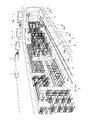
以下添付図面に基づいて、本発明の一実施形態の機械式自転車駐輪設備を詳細に説明する。図1は市街地に設置される機械式自転車駐輪設備の斜視図(地下部の斜視図)を示す。 Hereinafter, a mechanical bicycle parking facility according to an embodiment of the present invention will be described in detail with reference to the accompanying drawings. FIG. 1 is a perspective view (perspective view of an underground part) of a mechanical bicycle parking facility installed in an urban area.
地上部には、自転車を入出庫するための入出庫口としての入出庫ブース1が設けられる。この実施形態の入出庫ブース1は自転車の入庫と出庫を兼用している。入出庫ブース1には、入庫のために利用者が自転車をセットする受け渡し部1aが隣接して設けられる。出庫のときはこの受け渡し部1aまで自転車が自動的に戻る。
The ground portion is provided with a loading /
地下部には、複数段及び複数列の自転車収納部2aを有する保管棚2が配列される。地下部には、自転車を搬送する搬送装置としてのスタッカークレーン3が水平方向に走行可能に設けられる。スタッカークレーン3は保管棚2の列間を走行する。
A
機械式自転車駐輪設備の全体の動作の概略は以下のとおりである。利用者が受け渡し部に自転車をセットし、駐輪開始のボタンを押すと(又はカードを挿入すると)、入出庫ブース1の扉が開き、扉の中から昇降装置4の昇降装置用移載装置5(以下単に移載装置5という)が出てきて自転車の前輪を掴む。その後、移載装置5が受け渡し部1a上の自転車を入出庫ブース1内に引き込むと、入出庫ブース1の扉が閉じ、自転車を載せた昇降体4aが地上から地下部の中継装置7の高さまで下降する。自転車が中継装置7の高さまで下降したら、移載装置5が昇降体4a上の自転車を中継装置7に受け渡す。
The general operation of the mechanical bicycle parking facility is as follows. When a user sets a bicycle in the delivery section and presses a parking start button (or inserts a card), the door of the loading /
次に、自転車が渡された中継装置7は水平面内で旋回する。自転車が水平面内で所定角度回転したら中継装置7は回転を停止する。
Next, the
搬送装置としてのスタッカークレーン3は、中継装置7と自転車の受け渡しが行えるように中継装置7の近くに移動する。スタッカークレーン3の搬送装置用移載装置(以下単に移載装置8という)は中継装置7から自転車を受け取る。自転車を受け取ったら、スタッカークレーン3は目的の自転車収納部2aまで自転車を搬送し、移載装置8によって目的の自転車収納部2aに自転車を受け渡す。以上により自転車の入庫が終了する。
The
自転車を出庫するときは上記と逆の動作が行われる。入出庫ブース1、昇降装置4、中継装置7及びスタッカークレーン3は、図示しない監視室等に設けられる制御装置によって制御される。
When leaving the bicycle, the reverse operation is performed. The loading /
機械式自転車駐輪設備の各部の構造は以下のとおりである。入出庫ブース1は箱形状の建築物であり、移載装置5が出没可能な扉を有する。入出庫ブース1には、様々な形状・構造が存在する。例えば、押出し成形された成形板に扉や窓を埋め込み、全体を建築物として製造する場合もあるし、鋼板製の壁と天井を一体構造にし、デザインを良くする場合もある。いずれにしても、地下式自転車駐輪設備は市街地の駅前等に建設されるので、安全性はもとより、外観のよさやコンパクト化が要求される。
The structure of each part of the mechanical bicycle parking facility is as follows. The loading /
地下には、巨大な直方体形状のコンクリート製躯体からなる地下部9が構築される。地下部9は、通常の建築物のように現場打ちのコンクリートから構築されてもよいし、組み立てたプレキャストコンクリートから構築されてもよい。地下部には複数本の柱9aが所定の間隔を開けて配置される。
In the basement, an
地下部9には、上下方向に複数段、水平方向に複数列の自転車収納部2aを有する保管棚2が配列される。保管棚2は柱9aを避けて配置される。
In the
図2に示すように、保管棚2は、垂直方向に伸びる柱11、及び柱11間に渡される梁12からなる構造物を備える。各自転車収納部2aは、自転車の車輪が嵌まるV字形の棚部材2a1と、自転車の後輪の下部を挟む一対の板ばねを含む後輪保持部2a2と、自転車のスタンドを案内するスタンドガイド2a3と、を備える。自転車は自転車収納部2aに後輪側から収納される。自転車収納部2aに収納された自転車は後輪保持部2a2によって自立する。
As shown in FIG. 2, the
図3及び図4は地下部9の垂直断面図を示す。図3は昇降装置4の正面図を示し、図4は昇降装置4の側面図を示す。図3に示すように、入出庫ブース1の扉1bの手前には、利用者が自転車をセットする受け渡し部1aが設けられる。受け渡し部1aには、自転車の車輪が嵌まるV字形溝が形成される。V字形溝の、自転車の後輪に対応する部分には凹み1a1が設けられる。凹み1a1には、自転車を自立した状態で保持するための図示しない後輪保持部が設けられる。利用者が自転車をV字形溝に嵌め、自転車の後輪を凹みに嵌めると、後輪保持部が自転車を自立させる。受け渡し部1aの周囲は安全のための柵1a2で囲まれる。
3 and 4 show vertical sectional views of the
入出庫ブース1には、受け渡し部1aにセットされた自転車を中継装置7まで下降させる昇降装置4が設けられる。昇降装置4は地下の床面から立設する支柱4cと、支柱4cに取り付けられ、上下方向に伸びる左右一対のレール4bと、レール4bに沿って昇降可能な昇降体4aと、昇降体4aが吊り下げられるベルト4dと、ベルト4dを昇降させるサーボモータ4eと、を備える。ベルト4dの他端にはカウンターウェイト4fが吊り下げられる。ベルト4dには、支柱4cの上端に設けられ滑車4gが掛けられる。サーボモータ4eが滑車4gを回転させると、ベルト4dに吊り下げられる昇降体4aが昇降する。昇降体4aは地上部と中継装置7との間を往復する。支柱4cはその上端部が地面よりも上方に突出していて、支柱4cの上端部は入出庫ブース1で覆われる。
The loading /
昇降体4aには、自転車の前輪を掴んで自転車を受け渡し部1aから昇降体4a上に引き込む移載装置5が設けられる。移載装置5は、昇降体上に取り付けられ、自転車を案内するV字形の棚部材5aと、自転車の前輪の車軸を左右方向から掴むプレート状の一対のホルダ5bと、ホルダ5bを棚部材5aに沿ってスライドさせる駆動機構5cと、を備える。一対のホルダ5bはホルダ駆動機構によって互いの間隔が狭まったり開いたりする。一対のホルダ5bはプーリ5c1間に掛け渡された無端状のベルト5c2に連結されている。図示しないサーボモータによってプーリ5c1を回転駆動させると、ベルト5c2の周回に伴ってホルダ5bが棚部材5aに沿ってスライドする。なお、ホルダ5bは自転車の前輪の車軸ではなく、自転車の前輪自体を掴んでもよい。
The lifting / lowering
自転車を入庫するとき、昇降体4aは上端部まで上昇している。利用者が受け渡し部1aに自転車をセットすると、入出庫ブース1の扉が開き、昇降装置4の移載装置5が受け渡し部1aに向かって移動する。移載装置5のホルダ5bが自転車の前輪の車軸を掴んだら、移載装置5が自転車を昇降体4aの上に引き込む。移載装置5は自転車の前輪を掴んだままであるので、自転車は昇降体4a上で自立する。昇降装置4は昇降体4aを中継装置7の高さまで下降させる。
When the bicycle is stored, the elevating
なお、昇降装置4には上記にもさまざまな構造を採用することができる。例えば、カウンターウェイトを設けることなく、歯付きベルトとプーリによって昇降体4aを昇降させてもよいし、ワイヤーロープを巻き取るウィンチを用いてもよいし、リニアモータや送りねじ機構によって昇降体4aを昇降させてもよい。
Note that various structures can be employed for the lifting device 4 as described above. For example, without providing a counterweight, the elevating
中継装置7は、地下部の床面から立設する支柱18の上端部に回転可能に取り付けられる。中継装置7の高さは自転車収納部2aの最上段の高さ、この実施形態では4段目の高さに一致する。中継装置7は、水平方向に伸びるV字形の棚部材7aと、棚部材7aを水平面内で旋回させる旋回機構7bと、旋回機構7bを駆動するサーボモータ7cと、を備える。棚部材7aは支柱18の上端部にベアリングを介して回転可能に取り付けられる。旋回機構7bは、平歯車、ウォーム歯車等からなる。サーボモータ7cが旋回機構7bを駆動させると、棚部材7aが水平面内を旋回する。中継装置7の棚部材7aは、保管棚2と同様に、自転車の後輪を挟む一対の板ばねを含む後輪保持部7a1と、自転車のスタンドを案内するスタンドガイド7a2と、を備える。後輪保持部7a1が自転車の後輪を挟むことによって自転車が棚部材7a上に自立する。
The
昇降装置4が自転車を載せた昇降体4aを中継装置7の高さまで下降させたとき、中継装置7の棚部材7aは昇降体4aの方向を向くように旋回する。中継装置7の棚部材7aと昇降体4aの棚部材7aが一直線上に並んだら、昇降装置4の移載装置5が自転車を後輪側から中継装置7の棚部材7aに渡す。中継装置7に自転車を渡したら移載装置5はホルダ5bによるクランプを解除し、元の昇降体4a上に戻る。中継装置7は自転車を受け取った後、スタッカークレーン3の方向を向くように水平面内で旋回する。自転車は後輪保持部7a1に保持されているので、中継装置7が旋回しても自転車が落下することはない。
When the elevating device 4 lowers the elevating
次にスタッカークレーン3の構造を説明する。図1に示すように、地下躯体の床面及び天井には、保管棚2に沿って伸びる上下のレール14a,14bが設けられる。この実施形態では、天井に一本の上部レール14aが設けられ、床面に平行な一対の下部レール14bが設けられる。これらのレール14a,14bの間をスタッカークレーン3が走行する。
Next, the structure of the
図5はスタッカークレーン3の模式図を示す。スタッカークレーン3は、下部レール14b上を走行する台車3aと、台車3aから垂直方向に立設するマスト3bと、マスト3bに沿って昇降する昇降体3cと、昇降体3cに設けられる移載装置5と、移載装置5を水平面内で旋回させる旋回機構3eと、を備える。台車3aは左右一対の下部レール14b上を走行する4つの車輪3a1を有する。車輪3a1は図示しないサーボモータによって回転駆動される。
FIG. 5 shows a schematic diagram of the
図4に示すように、マスト3bの上端部には上部レール14aを挟むローラ3b1が設けられる。マスト3bの上端部は上部レール14aに案内される。マスト3bには、上下方向に伸びるレール13が取り付けられる。昇降体3cはこのレール13に沿って昇降する。昇降体3cはベルト14の一端に吊り下げられる。ベルト14の他端には、カウンターウェイト15が吊り下げられる。ベルト14はマスト3bの上端部に設けた滑車16に掛けられる。サーボモータ17によって滑車16を回転させると、昇降体3cがマスト3bに沿って昇降する。
As shown in FIG. 4, a roller 3b1 that sandwiches the
昇降体3cには、旋回機構3e(図5参照)を介して移載装置5が水平面内で旋回可能に取り付けられる。移載装置5の構造は上述の昇降装置4の移載装置と同一であるので同一の符号を附してその説明を省略する。移載装置5を旋回させる旋回機構3eは、平歯車、ウォーム歯車等の歯車と、歯車を回転駆動させるサーボモータ3e1と、を含む(図5参照)。サーボモータを駆動させると、移載装置5が水平面内を旋回する。スタッカークレーン3には、台車3aを走行させるためのサーボモータ、昇降体3cを昇降させるためのサーボモータ、移載装置5を動作させるサーボモータ、旋回機構3eを動作させるサーボモータを制御するための制御盤19が設けられる。
A
なお、図1に示すように、スタッカークレーン3の台車3aのフレーム3a2は枠状に形成される。昇降体3cが最下端まで下降したとき、フレーム3a2内に昇降体3cが入り込む(図4参照)。スタッカークレーン3に載せられた自転車を床面近くまで下降させることができるので、保管棚2を床面の近くまで配置することが可能になり、保管棚2の段数も増やすことが可能になる。
As shown in FIG. 1, the frame 3a2 of the
図6及び図7は地下部の平面図を示す。図6には、三つの入出庫ブース1の位置が示されている。一番右側の入出庫ブース1は地上の事情によって傾けられている。入出庫ブース1の下方には、自転車を下降させる昇降装置4が配置される。
6 and 7 show plan views of the underground part. FIG. 6 shows the positions of the three loading /
図6に示すように、中継装置7は昇降装置4に隣接して配置される。スタッカークレーン3は昇降装置4及び中継装置7の近くまで移動可能である。昇降装置4には支柱が設けられるので、スタッカークレーン3は昇降装置4まで移動することができない。このため、スタッカークレーン3のレール14bの一端は昇降装置4の手前で止められている。
As shown in FIG. 6, the
スタッカークレーン3のレーンの数は入出庫ブース1の数に対応しており、この図6には三つのレーンが示されている。レーンの左右には、多数段、多数列の自転車収納部2aを有する保管棚2が配列される。レーンの左右方向のピッチは一定に設定される。
The number of lanes of the
昇降装置4から中継装置7に自転車を渡すとき、中継装置7は昇降装置4の方向を向き、昇降装置4の移載装置5と中継装置7の棚部材7aとは一直線になっている。上述のように、昇降装置4の移載装置5は自転車の前輪を掴んだまま自転車を中継装置7に渡す。中継装置7では自転車の後輪が後輪保持部7a1によって保持される。昇降装置4から自転車を受け取ったら、中継装置7は40〜50度旋回し、スタッカークレーン3の方向を向く(図6中一点鎖線7a−1で示す)。上述のようにスタッカークレーン3は昇降装置4まで移動することができない。中継装置7を40〜50度回転させるのが、昇降装置4とスタッカークレーン3との干渉を避けた上で最もスペースを低減できる。
When the bicycle is transferred from the lifting device 4 to the
中継装置7の棚部材7aとスタッカークレーン3の移載装置5とが一直線になったら、スタッカークレーン3の移載装置5が中継装置7に向かってスライドし、中継装置7上の自転車の前輪を掴む。そして、自転車をスタッカークレーン3の昇降体3c上に引き込む。スタッカークレーン3は移載装置5を保管棚2の方向を向くように水平面内で旋回させ(図6中一点鎖線5−1で示す)、目的の自転車収納部2aの位置まで水平方向に移動し、目的の自転車収納部2aの高さまで昇降体を昇降させる。目的の自転車収納部2aの手前まで移載装置5を移動させたら、移載装置5が自転車を目的の保管棚2に渡す。以上により、自転車の自動的な入庫が可能になる。自転車の出庫動作は上記入庫動作と逆になる。
When the
本実施形態によれば、昇降装置4とスタッカークレーン3との間で直接的に自転車の受け渡しを行うことなく、水平面内で旋回可能な中継装置7を介して受け渡しを行うので、地上部の入出庫ブース1に対するスタッカークレーン3や保管棚2のレイアウトの自由度が広がる。例えば、図7に示すように、入出庫ブース1とスタッカークレーン3が平面的に離れて配置されても、これらの間に中継装置7を配置することで、自転車を受け渡すことが可能になる。
According to the present embodiment, since the bicycle is transferred directly between the elevating device 4 and the
昇降装置4に移載装置5を設け、スタッカークレーン3に移載装置5を設けることで、中継装置7に移載装置5を設ける必要がなくなり、昇降装置4と移載装置5とで自転車の同じ位置(上記実施形態では自転車の前輪)を掴むことができる。
Since the
旋回機能を有するスタッカークレーン3の移載装置5を保管棚2の自転車収納部2aの高さに合わせて昇降可能とすることで、保管棚2の各段の間にスタッカークレーン3を設ける必要がなくなり、保管棚2の各段の間にスタッカークレーン3のためのスペースが必要なくなる。このため、保管棚2の段数を増やすことができる。
It is necessary to provide the
なお、本発明は上記実施形態に限られることはなく、本発明の要旨を変更しない範囲で様々に変更可能である。 In addition, this invention is not limited to the said embodiment, In the range which does not change the summary of this invention, it can change variously.
例えば、上記実施形態では、地上部に入出庫口を設け、地下部に保管棚を設けているが、これに限定されるものではなく、入出庫口の階と保管棚の階とが異なっていればよい。例えば、ビルの屋上を自転車収納スペースとして利用してもよく、この場合、1階に入出庫口を設け、1階から屋上まで昇降装置で自転車を上昇させ、屋上の中継装置、スタッカークレーンを経由した後、屋上の保管棚に自転車を収納する。 For example, in the above embodiment, the entry / exit entrance is provided in the ground part and the storage shelf is provided in the basement part. However, the present invention is not limited to this, and the floor of the entry / exit entrance and the storage shelf are different. Just do it. For example, the roof of a building may be used as a bicycle storage space. In this case, an entrance / exit is provided on the first floor, and the bicycle is raised from the first floor to the roof by a lifting device, via a rooftop relay device and a stacker crane. After that, the bicycle is stored in a storage shelf on the roof.
上記実施形態では、自転車の入庫及び出庫を行う入出庫口を設けているが、入庫口と出庫口とを分けてもよい。 In the above-described embodiment, a loading / unloading port for loading and unloading bicycles is provided, but the loading / unloading port may be separated.
上記実施形態では、1つの入出庫口に対して1つのスタッカークレーンを設けているが、スタッカークレーンのレーン上に配置された2つの入出庫口に対して1つのスタッカークレーンを設けてもよい。 In the said embodiment, although one stacker crane is provided with respect to one loading / unloading port, you may provide one stacker crane with respect to two loading / unloading ports arrange | positioned on the lane of a stacker crane.
上記実施形態では、1つの中継装置から1つのスタッカークレーンに自転車を渡しているが、1つの中継装置から2つ以上のスタッカークレーンのいずれかに自転車を振り分けられるようにしてもよい。 In the above embodiment, a bicycle is passed from one relay device to one stacker crane, but the bicycle may be distributed from one relay device to one of two or more stacker cranes.
上記実施形態では、中継装置の棚部材を一段のみ設置しているが、中継装置の棚部材を複数段設けてもよい。例えば保管棚の3段目の高さや2段目の高さに中継装置の棚部材を設けてもよい。中継装置に複数の棚部材を設けると、バッファ機能がより高くなる。 In the above embodiment, only one shelf member of the relay device is installed, but a plurality of shelf members of the relay device may be provided. For example, the shelf member of the relay device may be provided at the height of the third stage or the second stage of the storage shelf. When a plurality of shelf members are provided in the relay device, the buffer function becomes higher.
1…入出庫ブース(入出庫口)
2…保管棚
2a…自転車収納部
3…スタッカークレーン(搬送装置)
3a…台車
3c…昇降体
3e…旋回機構
4…昇降装置
5…移載装置(昇降装置用移載装置,搬送装置用移載装置)
7…中継装置
1 ... Entry / exit booth (entrance / exit)
2 ...
3a ... cart 3c ... elevating
7 ... Relay device
Claims (5)
入出庫口と保管棚の階との間で自転車を昇降させる昇降装置と、
自転車を水平面内で旋回させる中継装置と、
自転車を少なくとも水平方向に搬送する搬送装置と、を備え、
前記昇降装置が自転車を前記中継装置の高さまで下降又は上昇させ、
前記昇降装置と前記中継装置との間で自転車の受け渡しを行い、
前記中継装置が前記昇降装置から受け渡された自転車を水平面内で旋回させ、
前記中継装置と前記搬送装置との間で自転車の受け渡しを行い、
前記搬送装置が前記中継装置から受け取った自転車を少なくとも水平方向に搬送し、前記保管棚に受け渡す機械式自転車駐輪設備。 In the mechanical bicycle parking facility that transports the bicycle set at the entrance / exit to the storage shelf provided with a different floor from the entrance / exit,
A lifting device that lifts and lowers the bicycle between the entrance and exit and the floor of the storage shelf;
A relay device for turning the bicycle in a horizontal plane;
A transport device for transporting the bicycle at least in the horizontal direction,
The lifting device lowers or raises the bicycle to the height of the relay device;
The bicycle is transferred between the lifting device and the relay device,
The relay device turns the bicycle passed from the lifting device in a horizontal plane,
The bicycle is transferred between the relay device and the transport device,
A mechanical bicycle parking facility in which the transport device transports the bicycle received from the relay device at least in the horizontal direction and delivers the bicycle to the storage shelf.
前記搬送装置には、前記中継装置から自転車を受け取り、前記保管棚に自転車を渡す搬送装置用移載装置が設けられることを特徴とする請求項1に記載の機械式自転車駐輪設備。 The lifting device is provided with a lifting device transfer device for passing a bicycle to the relay device,
The mechanical bicycle parking facility according to claim 1, wherein the transfer device is provided with a transfer device transfer device that receives a bicycle from the relay device and transfers the bicycle to the storage shelf.
前記搬送装置は、自転車を上下方向及び水平方向に搬送することを特徴とする請求項1又は2に記載の機械式自転車駐輪設備。 The storage shelf has a plurality of bicycle storage portions in the vertical direction and a plurality of rows in the horizontal direction,
The mechanical bicycle parking facility according to claim 1, wherein the transport device transports the bicycle in a vertical direction and a horizontal direction.
水平方向に移動可能な台車と、
前記台車に設けられ、前記中継装置及び前記保管棚の高さに合わせて昇降する昇降体と、
前記昇降体に設けられ、前記中継装置から自転車を受け取り、前記保管棚に自転車を渡す搬送装置用移載装置と、
前記搬送装置用移載装置を水平面内で旋回させる旋回機構と、を備えることを特徴とする請求項3に記載の機械式自転車駐輪設備。 The transfer device
A horizontally movable carriage,
A lifting body that is provided on the carriage and moves up and down according to the height of the relay device and the storage shelf;
A transfer device for transfer device that is provided on the lifting body, receives a bicycle from the relay device, and transfers the bicycle to the storage shelf;
The mechanical bicycle parking facility according to claim 3, further comprising: a turning mechanism that turns the transfer device transfer device in a horizontal plane.
昇降装置が自転車を入出庫口から保管棚の階の中継装置まで下降又は上昇させる工程と、
前記昇降装置と前記中継装置との間で自転車の受け渡しを行う工程と、
前記中継装置が前記昇降体から受け渡された自転車を水平面内で旋回させる工程と、
前記中継装置と搬送装置との間で自転車の受け渡しを行う工程と、
前記搬送装置が前記中継装置から受け取った自転車を少なくとも水平方向に搬送し、保管棚に自転車を受け渡す工程と、を備える機械式自転車駐輪方法。
In the mechanical bicycle parking method for transporting the bicycle set at the entrance / exit to the storage shelf provided with the floor different from the entrance / exit,
The lifting device lowers or raises the bicycle from the entrance / exit to the relay device on the floor of the storage shelf; and
Passing the bicycle between the lifting device and the relay device;
A step in which the relay device turns the bicycle delivered from the lifting body in a horizontal plane;
Passing the bicycle between the relay device and the transport device;
A mechanical bicycle parking method comprising: a step in which the transport device transports the bicycle received from the relay device in at least a horizontal direction and delivers the bicycle to a storage shelf.
Priority Applications (1)
| Application Number | Priority Date | Filing Date | Title |
|---|---|---|---|
| JP2011049201A JP5206827B2 (en) | 2011-03-07 | 2011-03-07 | Mechanical bicycle parking equipment and method |
Applications Claiming Priority (1)
| Application Number | Priority Date | Filing Date | Title |
|---|---|---|---|
| JP2011049201A JP5206827B2 (en) | 2011-03-07 | 2011-03-07 | Mechanical bicycle parking equipment and method |
Publications (2)
| Publication Number | Publication Date |
|---|---|
| JP2012184610A JP2012184610A (en) | 2012-09-27 |
| JP5206827B2 true JP5206827B2 (en) | 2013-06-12 |
Family
ID=47014902
Family Applications (1)
| Application Number | Title | Priority Date | Filing Date |
|---|---|---|---|
| JP2011049201A Active JP5206827B2 (en) | 2011-03-07 | 2011-03-07 | Mechanical bicycle parking equipment and method |
Country Status (1)
| Country | Link |
|---|---|
| JP (1) | JP5206827B2 (en) |
Families Citing this family (4)
| Publication number | Priority date | Publication date | Assignee | Title |
|---|---|---|---|---|
| JP5741626B2 (en) * | 2013-04-18 | 2015-07-01 | Jfeエンジニアリング株式会社 | Mechanical bicycle parking equipment and method |
| JP5672401B2 (en) * | 2013-04-18 | 2015-02-18 | Jfeエンジニアリング株式会社 | Mechanical bicycle parking equipment and method |
| JP6468092B2 (en) * | 2015-06-23 | 2019-02-13 | Jfeエンジニアリング株式会社 | Mechanical bicycle parking equipment and method |
| JP2019127803A (en) * | 2018-01-26 | 2019-08-01 | 株式会社技研製作所 | Bicycle parking system |
Family Cites Families (2)
| Publication number | Priority date | Publication date | Assignee | Title |
|---|---|---|---|---|
| JP3987918B2 (en) * | 1998-12-01 | 2007-10-10 | 光洋自動機株式会社 | Underground bicycle parking |
| JP2010261213A (en) * | 2009-05-07 | 2010-11-18 | Koyo Automatic Machine Co Ltd | Multistory bicycle parking device |
-
2011
- 2011-03-07 JP JP2011049201A patent/JP5206827B2/en active Active
Also Published As
| Publication number | Publication date |
|---|---|
| JP2012184610A (en) | 2012-09-27 |
Similar Documents
| Publication | Publication Date | Title |
|---|---|---|
| KR950002252B1 (en) | Multi-storey garage | |
| JP5206827B2 (en) | Mechanical bicycle parking equipment and method | |
| JP2015135029A (en) | Elevator type parking device | |
| JP5212507B2 (en) | Mechanical bicycle parking equipment and method | |
| JP5782933B2 (en) | Three-dimensional parking facilities | |
| JPH04281969A (en) | Elevator device for multi-level parking equipment | |
| JP2017008591A (en) | Mechanical bicycle parking facility and method | |
| JP2001329711A (en) | Multiple rows of parking garage | |
| JP5672401B2 (en) | Mechanical bicycle parking equipment and method | |
| JP4058684B2 (en) | High-rise multilevel parking system | |
| JP5741626B2 (en) | Mechanical bicycle parking equipment and method | |
| JP7214193B2 (en) | Elevator parking system for self-driving cars | |
| JPH09256661A (en) | Mechanical type high-rise parking device | |
| JP3701090B2 (en) | 3 column type elevating parking system | |
| JP7036894B1 (en) | Mechanical parking device and its entry / exit method | |
| JP2004263472A (en) | Three-dimensional bicycle parking device | |
| JP6133062B2 (en) | Multistage parking system | |
| JP5653134B2 (en) | Simultaneous elevator type parking system | |
| JP4341567B2 (en) | Boarding floor of parking equipment | |
| JPH03208970A (en) | Multistoried parking tower | |
| JPH06235269A (en) | Horizontal circulating system multistory garage | |
| JP2021134552A (en) | Pallet type lift device | |
| JP3800453B2 (en) | 3 column type elevating parking system | |
| JP2002309792A (en) | Lift type parking device | |
| JPH06200652A (en) | Elevator for multistory parking apparatus |
Legal Events
| Date | Code | Title | Description |
|---|---|---|---|
| A621 | Written request for application examination |
Free format text: JAPANESE INTERMEDIATE CODE: A621 Effective date: 20121210 |
|
| A871 | Explanation of circumstances concerning accelerated examination |
Free format text: JAPANESE INTERMEDIATE CODE: A871 Effective date: 20121210 |
|
| TRDD | Decision of grant or rejection written | ||
| A975 | Report on accelerated examination |
Free format text: JAPANESE INTERMEDIATE CODE: A971005 Effective date: 20130118 |
|
| A01 | Written decision to grant a patent or to grant a registration (utility model) |
Free format text: JAPANESE INTERMEDIATE CODE: A01 Effective date: 20130122 |
|
| A61 | First payment of annual fees (during grant procedure) |
Free format text: JAPANESE INTERMEDIATE CODE: A61 Effective date: 20130204 |
|
| FPAY | Renewal fee payment (event date is renewal date of database) |
Free format text: PAYMENT UNTIL: 20160301 Year of fee payment: 3 |
|
| R150 | Certificate of patent or registration of utility model |
Ref document number: 5206827 Country of ref document: JP Free format text: JAPANESE INTERMEDIATE CODE: R150 Free format text: JAPANESE INTERMEDIATE CODE: R150 |
|
| S531 | Written request for registration of change of domicile |
Free format text: JAPANESE INTERMEDIATE CODE: R313531 |
|
| R350 | Written notification of registration of transfer |
Free format text: JAPANESE INTERMEDIATE CODE: R350 |