JP5205984B2 - Vehicle bearing device - Google Patents
Vehicle bearing device Download PDFInfo
- Publication number
- JP5205984B2 JP5205984B2 JP2008009695A JP2008009695A JP5205984B2 JP 5205984 B2 JP5205984 B2 JP 5205984B2 JP 2008009695 A JP2008009695 A JP 2008009695A JP 2008009695 A JP2008009695 A JP 2008009695A JP 5205984 B2 JP5205984 B2 JP 5205984B2
- Authority
- JP
- Japan
- Prior art keywords
- groove
- end portion
- flange portion
- bearing device
- flange
- Prior art date
- Legal status (The legal status is an assumption and is not a legal conclusion. Google has not performed a legal analysis and makes no representation as to the accuracy of the status listed.)
- Expired - Fee Related
Links
Images


Description
本発明は、車両用軸受装置に関し、特に車両用軸受装置への水分浸入を抑制し、錆びの発生が従来に比べ低減された車両用軸受装置に関する。 The present invention relates to a vehicular bearing device, and more particularly to a vehicular bearing device in which moisture intrusion into the vehicular bearing device is suppressed and the occurrence of rust is reduced compared to the prior art.
一般に、自動車等に用いられる車両用軸受装置には、走行時に泥水等の水分の浸入を防止するための密封装置が備えられている。車両用軸受装置に水分が浸入すると車両用軸受装置内部に錆が生じたり、水分に混入している物質により軸受が焼きついたりする可能性があるためである。しかし、1組の密封装置のみで十分な防水効果を挙げることは困難であった。また、接触型の密封装置を他段階に組み合わせると、軸受の回転トルクの増加を招き、燃費が低下する。 Generally, a vehicular bearing device used in an automobile or the like is provided with a sealing device for preventing intrusion of moisture such as muddy water during traveling. This is because if moisture enters the vehicle bearing device, rust may be generated inside the vehicle bearing device, or the bearing may be burned by a substance mixed in the moisture. However, it has been difficult to obtain a sufficient waterproof effect with only one set of sealing devices. In addition, combining the contact-type sealing device at another stage increases the rotational torque of the bearing and reduces the fuel consumption.
そこで、車両用軸受装置内部を泥水等から保護する保護カバーを備え、シール装置(密封装置)よりも外径において外輪と内輪との間の開口部を覆いつつ、シール構造を形成する技術が開示されている。かかる構成により、密封装置(シール装置)に直接泥水等がかかることを防止し、且つ、保護カバーで覆われた箇所、即ちシール装置への泥水、異物等の浸入を防止することができ、シール装置のシール性能を長期にわたって維持することができると記載されている(例えば、特許文献1)。
しかし、上記特許文献1に記載の技術では、車両用軸受装置の防水能力は向上するものの、保護カバーを用いた泥除け構造等を軸受け装置に併設すると軸受装置全体の重量が増加するため、車両の軽量化を図ることが困難になるという問題があった。 However, in the technique described in Patent Document 1, although the waterproof capability of the vehicle bearing device is improved, if a mudguard structure using a protective cover is added to the bearing device, the weight of the entire bearing device increases. There was a problem that it was difficult to reduce the weight.
本発明は、かかる実情を鑑みて成されたもので、重量の増加を抑制しつつ、防水能力を向上させ、車両用軸受装置内部に錆が発生することを抑制することができる車両用軸受装置を提供することを課題とする。 The present invention has been made in view of the above circumstances, and is capable of improving the waterproof capability while suppressing an increase in weight and suppressing the occurrence of rust inside the vehicle bearing device. It is an issue to provide.
(1)本手段は、「車輪を支持する車両用軸受装置であって、前記車両用軸受装置は、回転部材を有し、前記回転部材は、フランジ部を有し、前記フランジ部は、前記回転部材から径方向外方に突出し、円環形状を有し、前記車輪が取り付けられる部分であって、外部面、反対面、排水構造、および複数の溝間部分を有し、前記外部面は、前記フランジ部において前記車輪が取り付けられる面を示し、前記反対面は、前記フランジ部における前記外部面とは反対側の面を示し、前記排水構造は、前記反対面に付着している水滴を前記回転部材が回転しているときの遠心力により寄せ集め、寄せ集めた水滴を前記フランジ部の径方向外方に排水する機能を有する構造であって、複数の溝を有し、前記溝は、前記反対面に形成され、前記フランジ部の径方向内方の部分から前記フランジ部の径方向外方の端部までにわたり形成され、溝内方部、溝外方部、および溝中間部を有し、前記溝内方部は、前記フランジ部の径方向内方の部分に形成され、前記溝外方部は、前記フランジ部の径方向外方の端部に形成され、前記フランジ部の周方向において前記溝内方部とは異なる箇所に形成され、前記溝中間部は、前記溝内方部と前記溝外方部との間に形成され、前記溝内方部から前記溝外方部に向けて曲がりながら伸びる形状を有し、前記溝間部分は、前記複数の溝のうちの1本と前記複数の溝のうちの別の1本との間に形成され、前記フランジ部の周方向における前記溝の幅は、前記フランジ部の周方向における前記溝間部分の幅よりも小さい車両用軸受装置」を含む。
(2)上記手段の一形態は、「前記フランジ部は、複数のボルト孔を有し、前記ボルト孔は、前記車輪と前記フランジ部とを互いに固定するボルトを挿入するための孔であって、前記溝間部分に形成される車両用軸受装置」を含む。
(3)上記手段の一形態は、「前記溝は、底面、第1側面、第2側面、第1境界部、および第2境界部を有し、前記第1側面は、前記複数の溝間部分のうちの1個の溝間部分の表面、および前記底面に連続する形状を有し、前記第2側面は、前記複数の溝間部分のうちの別の1個の溝間部分の表面、および前記底面に連続する形状を有し、前記第1境界部は、前記底面と前記第1側面との境界部分であって、第1内方端部および第1外方端部を有し、前記第2境界部は、前記底面と前記第2側面との境界部分であって、第2内方端部および第2外方端部を有し、前記溝内方部は、前記第1内方端部および前記第2内方端部を有し、前記溝外方部は、前記第1外方端部および前記第2外方端部を有し、前記第1内方端部は、前記第1境界部における径方向内方の端部を示し、前記第1外方端部は、前記第1境界部における径方向外方の端部を示し、前記フランジ部の周方向において前記第1内方端部に対して前記第2外方端部側の部分に形成され、前記第2内方端部は、前記第2境界部における径方向内方の端部を示し、前記第2外方端部は、前記第2境界部における径方向外方の端部を形成し、前記フランジ部の周方向において前記第2内方端部に対して前記第1内方端部側と反対側の部分、かつ前記第1外方端部に対して前記第1内方端部側と反対側の部分に形成される車両用軸受装置」を含む。
(4)上記手段の一形態は、「前記車両用軸受装置は、固定部材としての外輪、および前記回転部材としての内輪部材を有し、前記外輪は、前記回転部材を支持し、車両に固定される部品として形成され、前記内輪部材は、ハブ軸および内輪を有し、前記ハブ軸は、ハブ軸本体部および前記フランジ部を有し、前記フランジ部は、前記ハブ軸本体部における軸方向外部側の端部に形成され、外輪対向部分を有し、前記外輪対向部分は、前記フランジ部の径方向内方の部分を構成し、前記外輪における軸方向外部側の端部と対向する車両用軸受装置」を含む。
(1) This means is “a vehicle bearing device that supports a wheel, wherein the vehicle bearing device has a rotating member, the rotating member has a flange portion, and the flange portion A portion that protrudes radially outward from the rotating member, has an annular shape, and is attached to the wheel, and includes an outer surface, an opposite surface, a drainage structure, and a plurality of inter-groove portions, and the outer surface is The flange portion indicates a surface to which the wheel is attached, the opposite surface indicates a surface opposite to the outer surface of the flange portion, and the drainage structure has a water droplet attached to the opposite surface. A structure having a function of collecting the collected water droplets by centrifugal force when the rotating member is rotating and draining the collected water droplets outward in the radial direction of the flange portion, and having a plurality of grooves, The flange formed on the opposite surface Is formed over the radially inner portion to the end portion of the radially outer side of the flange portion, the groove inner portion, Mizogai side portions, and a groove intermediate portion, the groove inner portion, said Formed in a radially inner portion of the flange portion, the groove outer portion is formed at a radially outer end of the flange portion, and is different from the groove inner portion in the circumferential direction of the flange portion. The groove middle portion is formed between the groove inner portion and the groove outer portion, and has a shape that extends while bending from the groove inner portion toward the groove outer portion. The inter-groove portion is formed between one of the plurality of grooves and another one of the plurality of grooves, and the width of the groove in the circumferential direction of the flange portion is the flange A vehicle bearing device that is smaller than the width of the portion between the grooves in the circumferential direction of the portion.
(2) One form of the above means is that “the flange portion has a plurality of bolt holes, and the bolt holes are holes for inserting bolts for fixing the wheel and the flange portion to each other. , A vehicle bearing device formed in the portion between the grooves ”.
(3) One mode of the above means is that “the groove has a bottom surface, a first side surface, a second side surface, a first boundary portion, and a second boundary portion, and the first side surface is between the plurality of grooves. A surface of one inter-groove portion of the portion and a shape continuous to the bottom surface, and the second side surface is a surface of another inter-groove portion of the plurality of inter-groove portions, And the first boundary portion is a boundary portion between the bottom surface and the first side surface, and has a first inner end portion and a first outer end portion, The second boundary portion is a boundary portion between the bottom surface and the second side surface, and has a second inner end portion and a second outer end portion, and the groove inner portion is the first inner portion. An outer end portion and the second inner end portion, the outer groove portion has the first outer end portion and the second outer end portion, and the first inner end portion is At the first boundary The first outer end portion indicates the radially outer end portion of the first boundary portion, and the first inner end portion in the circumferential direction of the flange portion. The second inner end portion is a radially inner end portion of the second boundary portion, and the second outer end portion is formed on the second outer end portion side. Forming a radially outer end portion in the second boundary portion, and a portion opposite to the first inner end portion side with respect to the second inner end portion in the circumferential direction of the flange portion; and A vehicular bearing device formed on a portion of the first outer end opposite to the first inner end.
(4) One form of the above means is that “the vehicle bearing device has an outer ring as a fixing member and an inner ring member as the rotating member, and the outer ring supports the rotating member and is fixed to the vehicle. The inner ring member has a hub shaft and an inner ring, the hub shaft has a hub shaft main body portion and the flange portion, and the flange portion is an axial direction in the hub shaft main body portion. A vehicle that is formed at an outer end portion and has an outer ring facing portion, and the outer ring facing portion constitutes a radially inner portion of the flange portion and faces an end portion on the outer side in the axial direction of the outer ring. Bearing device ".
上記構成によると、フランジ部は、回転部材の回転状態において、回転部材の回転に伴う遠心力により、フランジ部に付着した水滴を寄せ集めるとともに、寄せ集めた前記水滴をラジアル方向において外方に排水する排水構造を有するため、フランジ部に付着した水滴が、車両用軸受装置内部に浸入することを抑制することができる。従って、フランジ部に付着した水滴が浸入することを原因とする車両用軸受装置内部における錆の発生を抑制することができる。また、錆の抑制効果はフランジ部の構造のみで達せられるため、特段の部品を追加する必要はない。従って、部材の増加による重量の増加を抑制することが可能となる。また、上記構成によると、排水構造は、フランジ部の車輪に固定される面の反対の面に設けられるとともに、フランジ部の中心部近傍からラジアル方向へ延設された複数のスパイラル状の溝であるため、フランジ部の車輪に固定される面の反対の面に付着した水滴は、回転部材の回転に伴って溝の内部に集められ、付着時より大きな水滴となる。また、大きくなった水滴は遠心力の影響を受けやすいため、溝に集められた水滴が、遠心力により跳ね飛ばされ、排水される。従って、回転部材の回転状態においては、フランジ部を伝って車両用軸受装置内部に水滴が浸入することが抑制される。 According to the above configuration, the flange portion collects water droplets attached to the flange portion by centrifugal force accompanying the rotation of the rotating member in the rotating state of the rotating member, and drains the collected water droplets outward in the radial direction. Therefore, it is possible to prevent water droplets adhering to the flange portion from entering the inside of the vehicle bearing device. Therefore, it is possible to suppress the occurrence of rust inside the vehicle bearing device due to the ingress of water droplets adhering to the flange portion. Moreover, since the effect of suppressing rust can be achieved only by the structure of the flange portion, it is not necessary to add special parts. Therefore, an increase in weight due to an increase in members can be suppressed. Further, according to the above configuration, the drainage structure is provided on the surface opposite to the surface fixed to the wheel of the flange portion, and includes a plurality of spiral grooves extending in the radial direction from the vicinity of the center portion of the flange portion. For this reason, water droplets adhering to the surface opposite to the surface fixed to the wheel of the flange portion are collected inside the groove as the rotating member rotates, resulting in larger water droplets than when adhering. Further, since the enlarged water droplets are easily affected by the centrifugal force, the water droplets collected in the groove are splashed and drained by the centrifugal force. Therefore, in the rotation state of the rotating member, water droplets are prevented from entering the vehicle bearing device through the flange portion.
(5)上記手段の一形態は、「前記車両用軸受装置は、請求項1〜3のいずれか一項に記載の前記回転部材に加えて固定部材および密封装置を有し、または、請求項4に記載の前記固定部材としての外輪および前記回転部材としての内輪部材に加えて密封装置を有し、前記密封装置は、前記固定部材に嵌合され、前記固定部材は、前記回転部材を支持し、車両に固定される部品であって、前記密封装置が嵌合される部分にメッキが施されている車両用軸受装置」を含む。(5) One form of the means is as follows: “The vehicle bearing device has a fixing member and a sealing device in addition to the rotating member according to any one of claims 1 to 3. 4. A sealing device is provided in addition to the outer ring as the fixing member and the inner ring member as the rotating member according to claim 4, wherein the sealing device is fitted to the fixing member, and the fixing member supports the rotating member. And a vehicle bearing device in which plating is applied to a portion that is fixed to the vehicle and to which the sealing device is fitted.
上記構成によると、固定部材の表面であるとともに密封装置が嵌合される部分がメッキ処理されているため、密封装置が嵌合される部分に錆が発生することを抑制できる。従って、車両用軸受装置内部における錆の発生を一層抑制することができる。また、錆の抑制効果はフランジ部の構造およびメッキで達せられるため、特段の部品を追加する必要はない。従って、部材の増加による重量の増加を抑制することが可能となる。 According to the said structure, since the part which is a surface of a fixing member and a sealing device is fitted is plated, it can suppress that rust generate | occur | produces in the part into which a sealing device is fitted. Therefore, the generation of rust in the vehicle bearing device can be further suppressed. Further, since the effect of suppressing rust can be achieved by the structure of the flange portion and plating, it is not necessary to add special parts. Therefore, an increase in weight due to an increase in members can be suppressed.
本発明によれば、重量の増加を抑制しつつ、防水能力を向上させ、車両用軸受装置内部に錆が発生することを抑制することができる車両用軸受装置を提供することができる。 ADVANTAGE OF THE INVENTION According to this invention, while suppressing the increase in weight, the waterproof capability can be improved and the vehicle bearing apparatus which can suppress that rust generate | occur | produces inside a vehicle bearing apparatus can be provided.
(第1の実施形態)
本発明を具体化した車両用軸受装置の一実施形態につき、図1〜図15を参照して、以下に説明する。
(First embodiment)
An embodiment of a vehicle bearing device embodying the present invention will be described below with reference to FIGS.
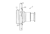
図1に示すように、固定部材としての略円筒形状の外輪4は、その外周面から径方向(ラジアル方向)において外方に突出したフランジ部7を介して、車両(不図示)に固定されている。また、軸方向(アキシャル方向)において外部側の端部内周面12aに錫メッキが施されるとともに、メッキが施された部分に密封装置13aが内嵌されている。同様に、軸方向において車体側の端部内周面12bにも錫メッキが施されるとともに、メッキが施された部分に密封装置13bが内嵌されている。更に、外輪4の内周面であるとともに、メッキが施された内周面12aの近傍車体側には、軌道面5aが設けられており、同様に、外輪4の内周面であるとともに、メッキが施された内周面12bの近傍外部側には、軌道面5bが設けられている。
As shown in FIG. 1, a substantially cylindrical outer ring 4 as a fixing member is fixed to a vehicle (not shown) via a flange portion 7 that protrudes outward in the radial direction (radial direction) from the outer peripheral surface thereof. ing. In addition, tin plating is applied to the outer peripheral surface 12a on the outer side in the axial direction (axial direction), and a
一方、車輪が固定される回転部材としての内輪部材1は、略円筒形状のハブ軸2、およびこのハブ軸2に嵌合固定された略円環形状の内輪3から構成されている。ハブ軸2の軸方向において外部側の端部には、軸方向において外部側に突出した円環状の案内部15と、径方向において外方に突出したフランジ部6とを備えている。なお、このフランジ部6を介してハブ軸2に車輪が固定される。また、ハブ軸2の軸方向において車体側の端部には小径部8が形成されており、小径部8の外周面に上述の内輪3が外嵌されている。ハブ軸2のフランジ部6より車体側の外周面であるとともに外輪4の軌道面5aに対応する位置には軌道面9aが形成されている。この軌道面5aと軌道面9aとの間に転動体11aが転動可能に介装されている。同様に、内輪3の外周面であるとともに外輪4の軌道面5bに対応する位置には軌道面9bが形成されている。この軌道面5bと軌道面9bとの間に転動体11bが転動可能に介装されている。また、外輪4の外部側端部に内嵌された密封装置13aはハブ軸2の内周面であるとともにフランジ部6の付根部分に摺接し、同様に、外輪4の車体側端部に内嵌された密封装置13bは内輪3の内周面であるとともに車体側端部に摺接している。
On the other hand, an inner ring member 1 as a rotating member to which a wheel is fixed is composed of a substantially
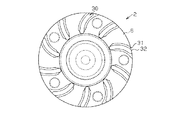
ここで、図2〜図15に示すように、上述したハブ軸2のフランジ部6の車輪が取り付けられる面6aの反対面6b、即ち、軸方向において車体側の面にはフランジ部6の中心部近傍から径方向において外方であるとともにハブ2の反回転方向へ延設された複数のスパイラル状の溝20が設けられている。この複数のスパイラル状の溝20がフランジ部6の車体側表面に付着した水滴を寄せ集め、遠心力により外方に排水する排水構造として機能する。
Here, as shown in FIGS. 2 to 15, the
より具体的には、ハブ軸2の回転状態においては、フランジ部6の車体側表面に付着した水滴には慣性力および空気との摩擦力が働くため、フランジ部6の回転速度より遅れて中心軸の周りを回転する。そのためフランジ部6の表面を滑る様に移動し、溝20に補足される。このようにして、フランジ部6の車体側表面に付着した水滴は溝20内に寄せ集められ、更に溝20の内壁21に押し付けられることにより一層大きな水滴となる。一方ハブ軸2は回転しているためハブ軸2とともに回転している水滴には、径方向において外方の遠心力が働いている。遠心力は物質の重量に比例して大きくなるので、水滴が大きくなるに従い、この遠心力も一層大きくなるため、水滴は径方向において外方に移動を開始する。また、遠心力は回転の中心から径方向において外方に位置するほど強く働くため、径方向において外方に移動するにつれ水滴に一層強い遠心力が働き、水滴は加速度的に径方向において外方に移動する。溝20の外方の端部22に達した水滴は、径方向において外方に振り飛ばされることにより、車両用軸受装置10の外部へ排水される。
More specifically, in the rotational state of the
また、外輪4の外部側端部を伝う水滴は密封装置13aにより軸方向において車体側に浸入することを防止される。また、外輪4の軸方向において外部側の端部内周面12aは錫メッキされているため、外輪4と密封装置13aとの界面に錆が生じたり、外輪4と密封装置13aとの界面から水分が浸入したりすることはない。同様に、外輪4の外部側端部を伝う水滴は密封装置13bにより軸方向において外部側に浸入することを防止される。外輪4の軸方向において車体側の端部内周面12bも錫メッキされているため、外輪4と密封装置13bとの界面に錆が生じたり、外輪4と密封装置13bとの界面から水分が浸入したりすることはない。
Further, water droplets traveling along the outer end of the outer ring 4 are prevented from entering the vehicle body in the axial direction by the
上記実施形態の車両用軸受装置によれば、以下のような効果を得ることができる。 According to the vehicle bearing device of the embodiment, the following effects can be obtained.
(1)上記実施形態にかかる車両用軸受装置によれば、フランジ部6は、ハブ軸2の回転状態において、遠心力によりフランジ部6に付着した水滴を排除する構造を有するため、フランジ部6に付着した水滴が、車両用軸受装置内部に浸入することを抑制することができる。従って、フランジ部6に付着した水滴が浸入することを原因とする車両用軸受装置10内部における錆の発生を抑制することができる。また、錆の抑制効果はフランジ部6の構造のみで達せられるため、特段の部品を追加する必要はない。従って、部材の増加による重量の増加を抑制することが可能となる。
(1) According to the vehicle bearing device according to the above-described embodiment, the
(2)上記実施形態にかかる車両用軸受装置10によれば、フランジ部6に付着した水滴を集めるための複数のスパイラル状の溝20が、車輪が取り付けられる面の反対面に設けられているため、フランジの、車輪が取り付けられる面の反対面に付着した水滴は、フランジが回転すると溝20の内部に集められ、付着時より大きな水滴となる。また、大きくなった水滴は遠心力の影響を受けやすいため、溝20に集められた水滴が、遠心力により跳ね飛ばされ、排除される。従って、回転部材の回転状態においては、フランジ部6を伝って車両用軸受装置内部に水滴が、浸入することが抑制される。
(2) According to the
(3)上記実施形態にかかる車両用軸受装置10によれば、フランジ部6に溝20が形成されているため、フランジ部の重量が従来より小さくなり、車両用軸受装置が軽量化される。
(3) According to the
(4)上記実施形態にかかる車両用軸受装置10によれば、固定部材の表面であるとともに密封装置が嵌合される部分がメッキ処理されているため、車両用軸受装置10内部における錆の発生を一層抑制することができる。また、錆の抑制効果はフランジ部6の構造およびメッキで達せられるため、特段の部品を追加する必要はない。従って、部材の増加による重量の増加を抑制することが可能となる。
(4) According to the
(第2の実施形態)
次に、本発明を具体化した車両用軸受装置の第2の実施形態を図16〜図29にしたがって説明する。なお、第2の実施形態は、第1の実施形態のフランジ部の形状を変更したのみの構成であるため、同様の部分についてはその詳細な説明を省略する。
(Second Embodiment)
Next, a vehicle bearing device according to a second embodiment of the present invention will be described with reference to FIGS. In addition, since 2nd Embodiment is a structure which only changed the shape of the flange part of 1st Embodiment, the detailed description is abbreviate | omitted about the same part.
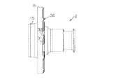
本実施形態においては、図16〜図29に示すように、ハブ軸2のフランジ部6の車輪が取り付けられる面6aの反対面6b、即ち、軸方向において車体側の面にはフランジ部6の中心部近傍から径方向において外方であるとともにハブ2の反回転方向へ延設された複数のスパイラル状のリブ30が設けられている。この複数のリブ30がフランジ部6の車体側表面に付着した水滴を寄せ集め、遠心力により外方に排水する排水構造として機能する。
In the present embodiment, as shown in FIGS. 16 to 29, the
より具体的には、ハブ軸2の回転状態においては、フランジ部6の車体側表面に付着した水滴には慣性力および空気との摩擦力が働くため、フランジ部6の回転速度より遅れて中心軸の周りを回転する。そのためフランジ部6の表面を滑る様に移動し、リブ30の側壁31に寄せ集められ、更にリブ30の側壁31に押し付けられることにより一層大きな水滴となる。一方ハブ軸2は回転しているためハブ軸2とともに回転している水滴には径方向において外方の遠心力が働いている。遠心力は物質の重量に比例して大きくなるので、水滴が大きくなるに従い、この遠心力も一層大きくなるため、水滴は径方向において外方に移動を開始する。また、遠心力は回転の中心から径方向において外方に位置するほど強く働くため、径方向において外方に移動するにつれ水滴に一層強い遠心力が働き、水滴は加速度的に径方向において外方に移動する。リブ30の側壁31の外方端部32に達した水滴は、径方向において外方に振り飛ばされることにより、車両用軸受装置10の外部へ排水される。
More specifically, in the rotational state of the
従って、第2の実施形態によれば、第1の実施形態に記載の効果に加えて以下の効果を得ることができる。 Therefore, according to the second embodiment, in addition to the effects described in the first embodiment, the following effects can be obtained.
(1)第2の実施形態にかかる車両用軸受装置10によれば、フランジ部6に付着した水滴を集めるための複数のスパイラル状のリブ30が、車輪が取り付けられる面の反対面に設けられているため、フランジ部6の、車輪が取り付けられる面の反対面に付着した水滴は、ハブ軸2の回転に伴ってフランジ部6が回転するとリブ30の側壁に集められ、付着時より大きな水滴となる。また、大きくなった水滴は遠心力の影響を受けやすいため、リブ30に集められた水滴が、遠心力により跳ね飛ばされ、排除される。従って、ハブ軸2の回転状態においては、フランジを伝って車両用軸受装置内部に水滴が浸入することが抑制される。
(1) According to the
(2)第2の実施形態にかかる車両用軸受装置10によれば、フランジ部6にリブ30が形成されているため、フランジ部の剛性が従来のフランジ部より大きくなり、車両用軸受装置の強度が増加する。
(2) According to the
なお、上記実施形態は以下のように変更してもよい。 In addition, you may change the said embodiment as follows.
・上記実施形態にかかる車両用軸受装置10において、外輪4の、軸方向において外部側の端部内周面12aに錫メッキが施されるとともに、メッキが施された部分に密封装置13aが内嵌されているが、他の構成であっても良い。即ち、外輪4と密封装置13aとの界面部分に錆が発生しなければ良いのであるから、防錆効果を有しかつ経済的合理性のある他の金属でメッキしても良く、非金属でコーティングしても良い。また、外輪4の軸方向において車体側の端部内周面12bについても同様である。
In the
・上記実施形態にかかる車両用軸受装置10において、外輪4の、軸方向において外部側の端部内周面12aに錫メッキが施されるとともに、メッキが施された部分に密封装置13aが内嵌されているが、錫メッキが施されない構成であっても良い。即ち、外輪4と密封装置13aとの界面部分に錆が発生しなければ良いのであるから、界面部分に浸入する蓋然性がなければ、メッキを割愛することができる。この構成によれば、メッキ工程が割愛できるため、コストダウンに資する。また、外輪4の軸方向において車体側の端部内周面12bについても同様である。
In the
・上記実施形態にかかる車両用軸受装置10において、外輪4の、軸方向において外部側の端部内周面12aに錫メッキが施されるとともに、メッキが施された部分に密封装置13aが内嵌されているが、内輪部材1にメッキを行い、メッキが施された部分に密封装置13aを外嵌する構成であっても良い。即ち、固定部材と密封装置13aとの界面部分に錆が発生しなければ良いのであるから、内輪部材が固定部材であればかかる構成が有効となる。また、外輪4の軸方向において車体側の端部内周面12bについても同様である。
In the
・上記実施形態にかかる車両用軸受装置10は、固定部材が外輪4であり、回転部材が内輪部材1である車両用軸受装置に適用されているが、固定部材が内輪部材であり、回転部材が外輪であっても適応可能である。即ち、回転軸のラジアル方向において外方に突出するとともに、回転部材を車輪に固定するためのフランジ部6を有する車両用軸受装置であればいずれにでも適応することができる。
The
本発明は、車両用軸受装置、特に水分が浸入しにくい車両用軸受装置であり、産業上広く利用可能である。 The present invention is a vehicle bearing device, particularly a vehicle bearing device in which moisture hardly enters, and can be widely used industrially.
1…内輪部材、2…ハブ軸、3…内輪、4…外輪、5a…軌道面、5b…軌道面、6…フランジ部、6a…車輪が取り付けられる面、6b…車輪が取り付けられる面の反対面、7…フランジ部、8…小径部、9a…軌道面、9b…軌道面、10…車両用軸受装置、11a…転動体、11b…転動体、12a…内周面、12b…内周面、13a…密封装置、13b…密封装置、15…案内部、20…溝、21…(溝の)内壁。22…(溝の)端部、30…リブ、31…(リブの)側壁、32…(リブの)端部。
DESCRIPTION OF SYMBOLS 1 ... Inner ring member, 2 ... Hub axle, 3 ... Inner ring, 4 ... Outer ring, 5a ... Race surface, 5b ... Race surface, 6 ... Flange part, 6a ... Surface where a wheel is attached, 6b ... Opposite to surface where a wheel is attached Surface 7, flange portion 8, small diameter portion 9 a,
Claims (5)
前記車両用軸受装置は、回転部材を有し、
前記回転部材は、フランジ部を有し、
前記フランジ部は、前記回転部材から径方向外方に突出し、円環形状を有し、前記車輪が取り付けられる部分であって、外部面、反対面、排水構造、および複数の溝間部分を有し、
前記外部面は、前記フランジ部において前記車輪が取り付けられる面を示し、
前記反対面は、前記フランジ部における前記外部面とは反対側の面を示し、
前記排水構造は、前記反対面に付着している水滴を前記回転部材が回転しているときの遠心力により寄せ集め、寄せ集めた水滴を前記フランジ部の径方向外方に排水する機能を有する構造であって、複数の溝を有し、
前記溝は、前記反対面に形成され、前記フランジ部の径方向内方の部分から前記フランジ部の径方向外方の端部までにわたり形成され、溝内方部、溝外方部、および溝中間部を有し、
前記溝内方部は、前記フランジ部の径方向内方の部分に形成され、
前記溝外方部は、前記フランジ部の径方向外方の端部に形成され、前記フランジ部の周方向において前記溝内方部とは異なる箇所に形成され、
前記溝中間部は、前記溝内方部と前記溝外方部との間に形成され、前記溝内方部から前記溝外方部に向けて曲がりながら伸びる形状を有し、
前記溝間部分は、前記複数の溝のうちの1本と前記複数の溝のうちの別の1本との間に形成され、
前記フランジ部の周方向における前記溝の幅は、前記フランジ部の周方向における前記溝間部分の幅よりも小さい
車両用軸受装置。 A vehicle bearing device for supporting wheels,
The vehicle bearing device has a rotating member,
The rotating member has a flange portion,
The flange portion protrudes radially outward from the rotating member, has an annular shape, and is a portion to which the wheel is attached, and has an outer surface, an opposite surface, a drainage structure, and a plurality of inter-groove portions. And
The outer surface indicates a surface to which the wheel is attached in the flange portion,
The opposite surface indicates a surface opposite to the outer surface in the flange portion,
The drainage structure has a function of collecting water droplets adhering to the opposite surface by centrifugal force when the rotating member is rotating, and draining the collected water droplets radially outward of the flange portion. A structure having a plurality of grooves,
The groove is formed on the opposite surface, and is formed from a radially inner portion of the flange portion to a radially outer end portion of the flange portion, and includes a groove inner portion, a groove outer portion, and a groove. Having an intermediate part,
The groove inner portion is formed in a radially inner portion of the flange portion,
The groove outer portion is formed at a radially outer end of the flange portion, and is formed at a location different from the groove inner portion in the circumferential direction of the flange portion,
The groove middle part is formed between the groove inner part and the groove outer part, and has a shape extending while bending from the groove inner part toward the groove outer part,
The inter-groove portion is formed between one of the plurality of grooves and another one of the plurality of grooves,
The width of the groove in the circumferential direction of the flange portion is smaller than the width of the inter-groove portion in the circumferential direction of the flange portion.
前記ボルト孔は、前記車輪と前記フランジ部とを互いに固定するボルトを挿入するための孔であって、前記溝間部分に形成される
請求項1に記載の車両用軸受装置。 The flange portion has a plurality of bolt holes,
The vehicular bearing device according to claim 1, wherein the bolt hole is a hole for inserting a bolt that fixes the wheel and the flange portion to each other, and is formed in the portion between the grooves.
前記第1側面は、前記複数の溝間部分のうちの1個の溝間部分の表面、および前記底面に連続する形状を有し、
前記第2側面は、前記複数の溝間部分のうちの別の1個の溝間部分の表面、および前記
底面に連続する形状を有し、
前記第1境界部は、前記底面と前記第1側面との境界部分であって、第1内方端部および第1外方端部を有し、
前記第2境界部は、前記底面と前記第2側面との境界部分であって、第2内方端部および第2外方端部を有し、
前記溝内方部は、前記第1内方端部および前記第2内方端部を有し、
前記溝外方部は、前記第1外方端部および前記第2外方端部を有し、
前記第1内方端部は、前記第1境界部における径方向内方の端部を示し、
前記第1外方端部は、前記第1境界部における径方向外方の端部を示し、前記フランジ部の周方向において前記第1内方端部に対して前記第2外方端部側の部分に形成され、
前記第2内方端部は、前記第2境界部における径方向内方の端部を示し、
前記第2外方端部は、前記第2境界部における径方向外方の端部を形成し、前記フランジ部の周方向において前記第2内方端部に対して前記第1内方端部側と反対側の部分、かつ前記第1外方端部に対して前記第1内方端部側と反対側の部分に形成される
請求項1または2に記載の車両用軸受装置。 The groove has a bottom surface, a first side surface, a second side surface, a first boundary portion, and a second boundary portion,
The first side surface has a shape that is continuous with the surface of one of the plurality of inter-groove portions and the bottom surface,
The second side surface has a shape continuous to the surface of another one of the plurality of inter-groove portions and the bottom surface,
The first boundary portion is a boundary portion between the bottom surface and the first side surface, and has a first inner end portion and a first outer end portion,
The second boundary portion is a boundary portion between the bottom surface and the second side surface, and has a second inner end portion and a second outer end portion,
The groove inner portion has the first inner end portion and the second inner end portion,
The groove outer portion has the first outer end portion and the second outer end portion,
The first inner end portion indicates a radially inner end portion of the first boundary portion,
The first outer end portion indicates a radially outer end portion of the first boundary portion, and the second outer end portion side with respect to the first inner end portion in the circumferential direction of the flange portion. Formed in the part of
The second inner end portion indicates a radially inner end portion of the second boundary portion,
The second outer end portion forms a radially outer end portion in the second boundary portion, and the first inner end portion with respect to the second inner end portion in the circumferential direction of the flange portion. The vehicular bearing device according to claim 1, wherein the vehicular bearing device is formed in a portion opposite to the side and in a portion opposite to the first inner end with respect to the first outer end.
前記外輪は、前記回転部材を支持し、車両に固定される部品として形成され、
前記内輪部材は、ハブ軸および内輪を有し、
前記ハブ軸は、ハブ軸本体部および前記フランジ部を有し、
前記フランジ部は、前記ハブ軸本体部における軸方向外部側の端部に形成され、外輪対向部分を有し、
前記外輪対向部分は、前記フランジ部の径方向内方の部分を構成し、前記外輪における軸方向外部側の端部と対向する
請求項1〜3のいずれか一項に記載の車両用軸受装置。 The vehicle bearing device has an outer ring as a fixed member, and an inner ring member as the rotating member,
The outer ring is formed as a part that supports the rotating member and is fixed to a vehicle,
The inner ring member has a hub shaft and an inner ring,
The hub shaft has a hub shaft main body portion and the flange portion,
The flange portion is formed at an end portion on the outer side in the axial direction of the hub shaft main body portion, and has an outer ring facing portion,
The vehicular bearing device according to any one of claims 1 to 3, wherein the outer ring facing portion constitutes a radially inner portion of the flange portion and faces an end portion on the outer side in the axial direction of the outer ring. .
前記密封装置は、前記固定部材に嵌合され、
前記固定部材は、前記回転部材を支持し、車両に固定される部品であって、前記密封装置が嵌合される部分にメッキが施されている
請求項1〜4のいずれか一項に記載の車両用軸受装置。 The vehicle bearing device includes a fixing member and a sealing device in addition to the rotating member according to any one of claims 1 to 3, or an outer ring as the fixing member according to claim 4 and In addition to the inner ring member as the rotating member, it has a sealing device,
The sealing device is fitted to the fixing member,
The said fixing member is a component which supports the said rotation member, and is fixed to a vehicle, Comprising: The part to which the said sealing device is fitted is plated. Vehicle bearing device.
Priority Applications (1)
| Application Number | Priority Date | Filing Date | Title |
|---|---|---|---|
| JP2008009695A JP5205984B2 (en) | 2008-01-18 | 2008-01-18 | Vehicle bearing device |
Applications Claiming Priority (1)
| Application Number | Priority Date | Filing Date | Title |
|---|---|---|---|
| JP2008009695A JP5205984B2 (en) | 2008-01-18 | 2008-01-18 | Vehicle bearing device |
Publications (3)
| Publication Number | Publication Date |
|---|---|
| JP2009166787A JP2009166787A (en) | 2009-07-30 |
| JP2009166787A5 JP2009166787A5 (en) | 2011-11-04 |
| JP5205984B2 true JP5205984B2 (en) | 2013-06-05 |
Family
ID=40968475
Family Applications (1)
| Application Number | Title | Priority Date | Filing Date |
|---|---|---|---|
| JP2008009695A Expired - Fee Related JP5205984B2 (en) | 2008-01-18 | 2008-01-18 | Vehicle bearing device |
Country Status (1)
| Country | Link |
|---|---|
| JP (1) | JP5205984B2 (en) |
Families Citing this family (3)
| Publication number | Priority date | Publication date | Assignee | Title |
|---|---|---|---|---|
| WO2015098896A1 (en) * | 2013-12-26 | 2015-07-02 | 株式会社 荏原製作所 | Bearing device and pump |
| WO2017179400A1 (en) | 2016-04-12 | 2017-10-19 | 日本精工株式会社 | Hub unit bearing |
| JP6787198B2 (en) * | 2016-04-12 | 2020-11-18 | 日本精工株式会社 | Hub unit bearing |
Family Cites Families (6)
| Publication number | Priority date | Publication date | Assignee | Title |
|---|---|---|---|---|
| JP2601171Y2 (en) * | 1993-03-31 | 1999-11-08 | いすゞ自動車株式会社 | Drainage structure of vehicle axle device |
| JP2002147473A (en) * | 2000-11-14 | 2002-05-22 | Koyo Seiko Co Ltd | Ball bearing for fishing tool and processing method therefor |
| JP2003269471A (en) * | 2002-03-18 | 2003-09-25 | Nsk Ltd | Bearing device for railway vehicle |
| JP2006161990A (en) * | 2004-12-09 | 2006-06-22 | Ntn Corp | Bearing for wheel |
| JP2007069731A (en) * | 2005-09-07 | 2007-03-22 | Nsk Ltd | Bearing unit |
| JP2007320417A (en) * | 2006-05-31 | 2007-12-13 | Jtekt Corp | Hub unit |
-
2008
- 2008-01-18 JP JP2008009695A patent/JP5205984B2/en not_active Expired - Fee Related
Also Published As
| Publication number | Publication date |
|---|---|
| JP2009166787A (en) | 2009-07-30 |
Similar Documents
| Publication | Publication Date | Title |
|---|---|---|
| JP4812263B2 (en) | Wheel bearing device | |
| WO2015005195A1 (en) | Roller bearing unit for supporting wheel having seal ring | |
| US20110148182A1 (en) | Steering knuckle with pre-sealing | |
| JP4466112B2 (en) | Rolling bearing unit for wheel support | |
| JP2010091036A (en) | Rolling bearing device | |
| JP5205984B2 (en) | Vehicle bearing device | |
| JP2013194908A (en) | Rolling bearing device for wheel | |
| JP3887349B2 (en) | Wheel support hub unit | |
| JP5773000B2 (en) | Hub unit bearing | |
| JP4692879B2 (en) | Hub unit | |
| JP2008002678A (en) | Wheel supporting structure | |
| JP2016109293A (en) | Rolling bearing unit for wheel support | |
| JP2008110659A (en) | Rolling bearing device for wheel | |
| JP2004074815A (en) | Rolling bearing device | |
| JP2016109183A (en) | Outer ring for rolling bearing unit, and rolling bearing unit for supporting wheel | |
| CN211975684U (en) | Combined sealing ring for hub bearing wheel side | |
| JP2013217419A (en) | Roller bearing device for wheel | |
| JP2011133053A (en) | Hub unit bearing | |
| US7819588B2 (en) | Bearing device for drive wheel | |
| JP2012087901A (en) | Sealing device and rolling bearing device | |
| JP2007269285A (en) | Hub unit | |
| JP7401974B2 (en) | Bearing device for wheels | |
| JP2011158017A (en) | Sealing device | |
| JP6819202B2 (en) | Bearing device for drive wheels | |
| JP6769234B2 (en) | Double row rolling bearing unit for wheel support |
Legal Events
| Date | Code | Title | Description |
|---|---|---|---|
| A621 | Written request for application examination |
Free format text: JAPANESE INTERMEDIATE CODE: A621 Effective date: 20101227 |
|
| A521 | Written amendment |
Free format text: JAPANESE INTERMEDIATE CODE: A523 Effective date: 20110810 |
|
| A521 | Written amendment |
Free format text: JAPANESE INTERMEDIATE CODE: A523 Effective date: 20110920 |
|
| A131 | Notification of reasons for refusal |
Free format text: JAPANESE INTERMEDIATE CODE: A131 Effective date: 20120918 |
|
| A977 | Report on retrieval |
Free format text: JAPANESE INTERMEDIATE CODE: A971007 Effective date: 20120920 |
|
| A521 | Written amendment |
Free format text: JAPANESE INTERMEDIATE CODE: A523 Effective date: 20121015 |
|
| A131 | Notification of reasons for refusal |
Free format text: JAPANESE INTERMEDIATE CODE: A131 Effective date: 20121128 |
|
| A521 | Written amendment |
Free format text: JAPANESE INTERMEDIATE CODE: A523 Effective date: 20121217 |
|
| TRDD | Decision of grant or rejection written | ||
| A01 | Written decision to grant a patent or to grant a registration (utility model) |
Free format text: JAPANESE INTERMEDIATE CODE: A01 Effective date: 20130122 |
|
| A61 | First payment of annual fees (during grant procedure) |
Free format text: JAPANESE INTERMEDIATE CODE: A61 Effective date: 20130204 |
|
| FPAY | Renewal fee payment (event date is renewal date of database) |
Free format text: PAYMENT UNTIL: 20160301 Year of fee payment: 3 |
|
| R150 | Certificate of patent or registration of utility model |
Ref document number: 5205984 Country of ref document: JP Free format text: JAPANESE INTERMEDIATE CODE: R150 Free format text: JAPANESE INTERMEDIATE CODE: R150 |
|
| LAPS | Cancellation because of no payment of annual fees |