JP5205466B2 - Tin and tin-zinc plated underlayer for improved performance of nickel-zinc cells - Google Patents
Tin and tin-zinc plated underlayer for improved performance of nickel-zinc cells Download PDFInfo
- Publication number
- JP5205466B2 JP5205466B2 JP2010528086A JP2010528086A JP5205466B2 JP 5205466 B2 JP5205466 B2 JP 5205466B2 JP 2010528086 A JP2010528086 A JP 2010528086A JP 2010528086 A JP2010528086 A JP 2010528086A JP 5205466 B2 JP5205466 B2 JP 5205466B2
- Authority
- JP
- Japan
- Prior art keywords
- zinc
- layer
- nickel
- underlayer
- tin
- Prior art date
- Legal status (The legal status is an assumption and is not a legal conclusion. Google has not performed a legal analysis and makes no representation as to the accuracy of the status listed.)
- Active
Links
- QELJHCBNGDEXLD-UHFFFAOYSA-N nickel zinc Chemical compound [Ni].[Zn] QELJHCBNGDEXLD-UHFFFAOYSA-N 0.000 title claims description 34
- GZCWPZJOEIAXRU-UHFFFAOYSA-N tin zinc Chemical compound [Zn].[Sn] GZCWPZJOEIAXRU-UHFFFAOYSA-N 0.000 title description 6
- 239000010949 copper Substances 0.000 claims description 69
- ATJFFYVFTNAWJD-UHFFFAOYSA-N Tin Chemical compound [Sn] ATJFFYVFTNAWJD-UHFFFAOYSA-N 0.000 claims description 56
- 229910052718 tin Inorganic materials 0.000 claims description 51
- PXHVJJICTQNCMI-UHFFFAOYSA-N Nickel Chemical compound [Ni] PXHVJJICTQNCMI-UHFFFAOYSA-N 0.000 claims description 50
- RYGMFSIKBFXOCR-UHFFFAOYSA-N Copper Chemical compound [Cu] RYGMFSIKBFXOCR-UHFFFAOYSA-N 0.000 claims description 49
- 229910052802 copper Inorganic materials 0.000 claims description 44
- 229910000765 intermetallic Inorganic materials 0.000 claims description 41
- 238000007747 plating Methods 0.000 claims description 41
- XLOMVQKBTHCTTD-UHFFFAOYSA-N Zinc monoxide Chemical compound [Zn]=O XLOMVQKBTHCTTD-UHFFFAOYSA-N 0.000 claims description 36
- 229910001369 Brass Inorganic materials 0.000 claims description 25
- 229910017482 Cu 6 Sn 5 Inorganic materials 0.000 claims description 25
- 239000010951 brass Substances 0.000 claims description 24
- 238000002955 isolation Methods 0.000 claims description 24
- 229910052759 nickel Inorganic materials 0.000 claims description 21
- 239000011262 electrochemically active material Substances 0.000 claims description 19
- 238000010304 firing Methods 0.000 claims description 18
- 239000011787 zinc oxide Substances 0.000 claims description 18
- 239000010410 layer Substances 0.000 description 102
- 210000004027 cell Anatomy 0.000 description 100
- 239000011135 tin Substances 0.000 description 76
- 239000011701 zinc Substances 0.000 description 64
- HCHKCACWOHOZIP-UHFFFAOYSA-N Zinc Chemical compound [Zn] HCHKCACWOHOZIP-UHFFFAOYSA-N 0.000 description 63
- 229910052725 zinc Inorganic materials 0.000 description 60
- 239000000463 material Substances 0.000 description 47
- 238000000034 method Methods 0.000 description 37
- 239000007789 gas Substances 0.000 description 33
- 229910052751 metal Inorganic materials 0.000 description 32
- 239000002184 metal Substances 0.000 description 30
- 238000004519 manufacturing process Methods 0.000 description 27
- 239000003792 electrolyte Substances 0.000 description 24
- 238000009713 electroplating Methods 0.000 description 23
- 239000000243 solution Substances 0.000 description 22
- 239000002253 acid Substances 0.000 description 20
- UFHFLCQGNIYNRP-UHFFFAOYSA-N Hydrogen Chemical compound [H][H] UFHFLCQGNIYNRP-UHFFFAOYSA-N 0.000 description 18
- 239000001257 hydrogen Substances 0.000 description 18
- 229910052739 hydrogen Inorganic materials 0.000 description 18
- 239000006260 foam Substances 0.000 description 17
- 230000015572 biosynthetic process Effects 0.000 description 16
- 230000007797 corrosion Effects 0.000 description 15
- 238000005260 corrosion Methods 0.000 description 15
- 239000000126 substance Substances 0.000 description 15
- QAOWNCQODCNURD-UHFFFAOYSA-N Sulfuric acid Chemical compound OS(O)(=O)=O QAOWNCQODCNURD-UHFFFAOYSA-N 0.000 description 14
- -1 cresol sulfone Chemical class 0.000 description 14
- 238000001994 activation Methods 0.000 description 13
- 238000013461 design Methods 0.000 description 13
- 238000001764 infiltration Methods 0.000 description 13
- 230000008595 infiltration Effects 0.000 description 13
- 230000003647 oxidation Effects 0.000 description 13
- 238000007254 oxidation reaction Methods 0.000 description 13
- 230000008569 process Effects 0.000 description 12
- 229910001128 Sn alloy Inorganic materials 0.000 description 11
- 230000004913 activation Effects 0.000 description 11
- 239000000654 additive Substances 0.000 description 11
- 239000003795 chemical substances by application Substances 0.000 description 10
- 229910001432 tin ion Inorganic materials 0.000 description 10
- 229910000881 Cu alloy Inorganic materials 0.000 description 9
- HEMHJVSKTPXQMS-UHFFFAOYSA-M Sodium hydroxide Chemical compound [OH-].[Na+] HEMHJVSKTPXQMS-UHFFFAOYSA-M 0.000 description 9
- 229930003836 cresol Natural products 0.000 description 9
- PTFCDOFLOPIGGS-UHFFFAOYSA-N Zinc dication Chemical compound [Zn+2] PTFCDOFLOPIGGS-UHFFFAOYSA-N 0.000 description 8
- 230000004888 barrier function Effects 0.000 description 8
- 238000004140 cleaning Methods 0.000 description 8
- 150000001875 compounds Chemical class 0.000 description 8
- 239000000203 mixture Substances 0.000 description 8
- 239000004094 surface-active agent Substances 0.000 description 8
- 238000012360 testing method Methods 0.000 description 8
- XLYOFNOQVPJJNP-UHFFFAOYSA-N water Substances O XLYOFNOQVPJJNP-UHFFFAOYSA-N 0.000 description 8
- KJCVRFUGPWSIIH-UHFFFAOYSA-N 1-naphthol Chemical compound C1=CC=C2C(O)=CC=CC2=C1 KJCVRFUGPWSIIH-UHFFFAOYSA-N 0.000 description 7
- QTWJRLJHJPIABL-UHFFFAOYSA-N 2-methylphenol;3-methylphenol;4-methylphenol Chemical compound CC1=CC=C(O)C=C1.CC1=CC=CC(O)=C1.CC1=CC=CC=C1O QTWJRLJHJPIABL-UHFFFAOYSA-N 0.000 description 7
- QTBSBXVTEAMEQO-UHFFFAOYSA-N Acetic acid Chemical compound CC(O)=O QTBSBXVTEAMEQO-UHFFFAOYSA-N 0.000 description 7
- 108010010803 Gelatin Proteins 0.000 description 7
- 239000000853 adhesive Substances 0.000 description 7
- 230000001070 adhesive effect Effects 0.000 description 7
- 239000007844 bleaching agent Substances 0.000 description 7
- 239000008273 gelatin Substances 0.000 description 7
- 229920000159 gelatin Polymers 0.000 description 7
- 235000019322 gelatine Nutrition 0.000 description 7
- 235000011852 gelatine desserts Nutrition 0.000 description 7
- 229910019142 PO4 Inorganic materials 0.000 description 6
- KWYUFKZDYYNOTN-UHFFFAOYSA-M Potassium hydroxide Chemical compound [OH-].[K+] KWYUFKZDYYNOTN-UHFFFAOYSA-M 0.000 description 6
- CDBYLPFSWZWCQE-UHFFFAOYSA-L Sodium Carbonate Chemical compound [Na+].[Na+].[O-]C([O-])=O CDBYLPFSWZWCQE-UHFFFAOYSA-L 0.000 description 6
- 229910045601 alloy Inorganic materials 0.000 description 6
- 239000000956 alloy Substances 0.000 description 6
- OJIJEKBXJYRIBZ-UHFFFAOYSA-N cadmium nickel Chemical compound [Ni].[Cd] OJIJEKBXJYRIBZ-UHFFFAOYSA-N 0.000 description 6
- 239000010406 cathode material Substances 0.000 description 6
- 239000007772 electrode material Substances 0.000 description 6
- 230000001788 irregular Effects 0.000 description 6
- 235000021317 phosphate Nutrition 0.000 description 6
- 229920000642 polymer Polymers 0.000 description 6
- 239000011148 porous material Substances 0.000 description 6
- LWIHDJKSTIGBAC-UHFFFAOYSA-K tripotassium phosphate Chemical compound [K+].[K+].[K+].[O-]P([O-])([O-])=O LWIHDJKSTIGBAC-UHFFFAOYSA-K 0.000 description 6
- NWONKYPBYAMBJT-UHFFFAOYSA-L zinc sulfate Chemical compound [Zn+2].[O-]S([O-])(=O)=O NWONKYPBYAMBJT-UHFFFAOYSA-L 0.000 description 6
- OYPRJOBELJOOCE-UHFFFAOYSA-N Calcium Chemical compound [Ca] OYPRJOBELJOOCE-UHFFFAOYSA-N 0.000 description 5
- BVKZGUZCCUSVTD-UHFFFAOYSA-L Carbonate Chemical compound [O-]C([O-])=O BVKZGUZCCUSVTD-UHFFFAOYSA-L 0.000 description 5
- 239000004743 Polypropylene Substances 0.000 description 5
- 229910001297 Zn alloy Inorganic materials 0.000 description 5
- 230000003213 activating effect Effects 0.000 description 5
- QVGXLLKOCUKJST-UHFFFAOYSA-N atomic oxygen Chemical compound [O] QVGXLLKOCUKJST-UHFFFAOYSA-N 0.000 description 5
- 229910052791 calcium Inorganic materials 0.000 description 5
- 239000011575 calcium Substances 0.000 description 5
- 238000010276 construction Methods 0.000 description 5
- 210000001787 dendrite Anatomy 0.000 description 5
- 238000009792 diffusion process Methods 0.000 description 5
- XLYOFNOQVPJJNP-UHFFFAOYSA-M hydroxide Chemical compound [OH-] XLYOFNOQVPJJNP-UHFFFAOYSA-M 0.000 description 5
- 239000001301 oxygen Substances 0.000 description 5
- 229910052760 oxygen Inorganic materials 0.000 description 5
- 239000002245 particle Substances 0.000 description 5
- 229920001155 polypropylene Polymers 0.000 description 5
- 239000004698 Polyethylene Substances 0.000 description 4
- 239000004372 Polyvinyl alcohol Substances 0.000 description 4
- VYPSYNLAJGMNEJ-UHFFFAOYSA-N Silicium dioxide Chemical compound O=[Si]=O VYPSYNLAJGMNEJ-UHFFFAOYSA-N 0.000 description 4
- 229910052797 bismuth Inorganic materials 0.000 description 4
- JCXGWMGPZLAOME-UHFFFAOYSA-N bismuth atom Chemical compound [Bi] JCXGWMGPZLAOME-UHFFFAOYSA-N 0.000 description 4
- 229910000416 bismuth oxide Inorganic materials 0.000 description 4
- TYIXMATWDRGMPF-UHFFFAOYSA-N dibismuth;oxygen(2-) Chemical compound [O-2].[O-2].[O-2].[Bi+3].[Bi+3] TYIXMATWDRGMPF-UHFFFAOYSA-N 0.000 description 4
- 230000006870 function Effects 0.000 description 4
- 229910052738 indium Inorganic materials 0.000 description 4
- APFVFJFRJDLVQX-UHFFFAOYSA-N indium atom Chemical compound [In] APFVFJFRJDLVQX-UHFFFAOYSA-N 0.000 description 4
- 229910003437 indium oxide Inorganic materials 0.000 description 4
- PJXISJQVUVHSOJ-UHFFFAOYSA-N indium(iii) oxide Chemical compound [O-2].[O-2].[O-2].[In+3].[In+3] PJXISJQVUVHSOJ-UHFFFAOYSA-N 0.000 description 4
- 239000011133 lead Substances 0.000 description 4
- 239000011159 matrix material Substances 0.000 description 4
- 230000007246 mechanism Effects 0.000 description 4
- 239000012528 membrane Substances 0.000 description 4
- NBIIXXVUZAFLBC-UHFFFAOYSA-K phosphate Chemical compound [O-]P([O-])([O-])=O NBIIXXVUZAFLBC-UHFFFAOYSA-K 0.000 description 4
- 239000010452 phosphate Substances 0.000 description 4
- 229920001467 poly(styrenesulfonates) Polymers 0.000 description 4
- 229920000573 polyethylene Polymers 0.000 description 4
- 239000011970 polystyrene sulfonate Substances 0.000 description 4
- 229960002796 polystyrene sulfonate Drugs 0.000 description 4
- 229920002451 polyvinyl alcohol Polymers 0.000 description 4
- BWHMMNNQKKPAPP-UHFFFAOYSA-L potassium carbonate Chemical compound [K+].[K+].[O-]C([O-])=O BWHMMNNQKKPAPP-UHFFFAOYSA-L 0.000 description 4
- 230000006798 recombination Effects 0.000 description 4
- 238000005215 recombination Methods 0.000 description 4
- 239000001488 sodium phosphate Substances 0.000 description 4
- 235000011008 sodium phosphates Nutrition 0.000 description 4
- RCIVOBGSMSSVTR-UHFFFAOYSA-L stannous sulfate Chemical compound [SnH2+2].[O-]S([O-])(=O)=O RCIVOBGSMSSVTR-UHFFFAOYSA-L 0.000 description 4
- 150000003457 sulfones Chemical class 0.000 description 4
- 229910000375 tin(II) sulfate Inorganic materials 0.000 description 4
- 239000011800 void material Substances 0.000 description 4
- JIAARYAFYJHUJI-UHFFFAOYSA-L zinc dichloride Chemical compound [Cl-].[Cl-].[Zn+2] JIAARYAFYJHUJI-UHFFFAOYSA-L 0.000 description 4
- 229920002134 Carboxymethyl cellulose Polymers 0.000 description 3
- 229910018471 Cu6Sn5 Inorganic materials 0.000 description 3
- OKKJLVBELUTLKV-UHFFFAOYSA-N Methanol Chemical compound OC OKKJLVBELUTLKV-UHFFFAOYSA-N 0.000 description 3
- 239000004677 Nylon Substances 0.000 description 3
- 229910000831 Steel Inorganic materials 0.000 description 3
- 150000007513 acids Chemical class 0.000 description 3
- 150000001450 anions Chemical class 0.000 description 3
- 238000006243 chemical reaction Methods 0.000 description 3
- 238000000576 coating method Methods 0.000 description 3
- 229910017052 cobalt Inorganic materials 0.000 description 3
- 239000010941 cobalt Substances 0.000 description 3
- GUTLYIVDDKVIGB-UHFFFAOYSA-N cobalt atom Chemical compound [Co] GUTLYIVDDKVIGB-UHFFFAOYSA-N 0.000 description 3
- 238000005238 degreasing Methods 0.000 description 3
- 238000007599 discharging Methods 0.000 description 3
- 238000001035 drying Methods 0.000 description 3
- 230000002209 hydrophobic effect Effects 0.000 description 3
- 239000003112 inhibitor Substances 0.000 description 3
- 238000005342 ion exchange Methods 0.000 description 3
- 150000002500 ions Chemical class 0.000 description 3
- 235000015110 jellies Nutrition 0.000 description 3
- 239000008274 jelly Substances 0.000 description 3
- 238000005259 measurement Methods 0.000 description 3
- BFDHFSHZJLFAMC-UHFFFAOYSA-L nickel(ii) hydroxide Chemical compound [OH-].[OH-].[Ni+2] BFDHFSHZJLFAMC-UHFFFAOYSA-L 0.000 description 3
- 229920001778 nylon Polymers 0.000 description 3
- TWNQGVIAIRXVLR-UHFFFAOYSA-N oxo(oxoalumanyloxy)alumane Chemical compound O=[Al]O[Al]=O TWNQGVIAIRXVLR-UHFFFAOYSA-N 0.000 description 3
- 230000035515 penetration Effects 0.000 description 3
- 229920001343 polytetrafluoroethylene Polymers 0.000 description 3
- 239000004810 polytetrafluoroethylene Substances 0.000 description 3
- 235000011009 potassium phosphates Nutrition 0.000 description 3
- 229910000029 sodium carbonate Inorganic materials 0.000 description 3
- 229910000162 sodium phosphate Inorganic materials 0.000 description 3
- 239000010959 steel Substances 0.000 description 3
- 238000003860 storage Methods 0.000 description 3
- 125000000542 sulfonic acid group Chemical group 0.000 description 3
- RYFMWSXOAZQYPI-UHFFFAOYSA-K trisodium phosphate Chemical compound [Na+].[Na+].[Na+].[O-]P([O-])([O-])=O RYFMWSXOAZQYPI-UHFFFAOYSA-K 0.000 description 3
- 238000009423 ventilation Methods 0.000 description 3
- 238000013022 venting Methods 0.000 description 3
- 238000003466 welding Methods 0.000 description 3
- 229960001763 zinc sulfate Drugs 0.000 description 3
- 229910000368 zinc sulfate Inorganic materials 0.000 description 3
- TXUICONDJPYNPY-UHFFFAOYSA-N (1,10,13-trimethyl-3-oxo-4,5,6,7,8,9,11,12,14,15,16,17-dodecahydrocyclopenta[a]phenanthren-17-yl) heptanoate Chemical compound C1CC2CC(=O)C=C(C)C2(C)C2C1C1CCC(OC(=O)CCCCCC)C1(C)CC2 TXUICONDJPYNPY-UHFFFAOYSA-N 0.000 description 2
- WHOZNOZYMBRCBL-OUKQBFOZSA-N (2E)-2-Tetradecenal Chemical compound CCCCCCCCCCC\C=C\C=O WHOZNOZYMBRCBL-OUKQBFOZSA-N 0.000 description 2
- CSCPPACGZOOCGX-UHFFFAOYSA-N Acetone Chemical compound CC(C)=O CSCPPACGZOOCGX-UHFFFAOYSA-N 0.000 description 2
- LFQSCWFLJHTTHZ-UHFFFAOYSA-N Ethanol Chemical compound CCO LFQSCWFLJHTTHZ-UHFFFAOYSA-N 0.000 description 2
- VEXZGXHMUGYJMC-UHFFFAOYSA-N Hydrochloric acid Chemical compound Cl VEXZGXHMUGYJMC-UHFFFAOYSA-N 0.000 description 2
- 229920000663 Hydroxyethyl cellulose Polymers 0.000 description 2
- AFVFQIVMOAPDHO-UHFFFAOYSA-N Methanesulfonic acid Chemical compound CS(O)(=O)=O AFVFQIVMOAPDHO-UHFFFAOYSA-N 0.000 description 2
- PMZURENOXWZQFD-UHFFFAOYSA-L Sodium Sulfate Chemical compound [Na+].[Na+].[O-]S([O-])(=O)=O PMZURENOXWZQFD-UHFFFAOYSA-L 0.000 description 2
- VMHLLURERBWHNL-UHFFFAOYSA-M Sodium acetate Chemical compound [Na+].CC([O-])=O VMHLLURERBWHNL-UHFFFAOYSA-M 0.000 description 2
- 229910021626 Tin(II) chloride Inorganic materials 0.000 description 2
- GWEVSGVZZGPLCZ-UHFFFAOYSA-N Titan oxide Chemical compound O=[Ti]=O GWEVSGVZZGPLCZ-UHFFFAOYSA-N 0.000 description 2
- 239000013543 active substance Substances 0.000 description 2
- 230000000996 additive effect Effects 0.000 description 2
- 230000002411 adverse Effects 0.000 description 2
- 239000012670 alkaline solution Substances 0.000 description 2
- 239000011324 bead Substances 0.000 description 2
- JALQQBGHJJURDQ-UHFFFAOYSA-L bis(methylsulfonyloxy)tin Chemical compound [Sn+2].CS([O-])(=O)=O.CS([O-])(=O)=O JALQQBGHJJURDQ-UHFFFAOYSA-L 0.000 description 2
- KGBXLFKZBHKPEV-UHFFFAOYSA-N boric acid Chemical compound OB(O)O KGBXLFKZBHKPEV-UHFFFAOYSA-N 0.000 description 2
- 239000004327 boric acid Substances 0.000 description 2
- 150000001642 boronic acid derivatives Chemical class 0.000 description 2
- 230000015556 catabolic process Effects 0.000 description 2
- 230000022131 cell cycle Effects 0.000 description 2
- 239000011248 coating agent Substances 0.000 description 2
- IVMYJDGYRUAWML-UHFFFAOYSA-N cobalt(ii) oxide Chemical compound [Co]=O IVMYJDGYRUAWML-UHFFFAOYSA-N 0.000 description 2
- 230000007423 decrease Effects 0.000 description 2
- 238000006731 degradation reaction Methods 0.000 description 2
- 239000011928 denatured alcohol Substances 0.000 description 2
- 238000010586 diagram Methods 0.000 description 2
- 239000002270 dispersing agent Substances 0.000 description 2
- 230000000694 effects Effects 0.000 description 2
- 238000011049 filling Methods 0.000 description 2
- 150000004673 fluoride salts Chemical class 0.000 description 2
- 238000009472 formulation Methods 0.000 description 2
- 239000000446 fuel Substances 0.000 description 2
- 239000000499 gel Substances 0.000 description 2
- 229910001416 lithium ion Inorganic materials 0.000 description 2
- 231100000053 low toxicity Toxicity 0.000 description 2
- 239000007773 negative electrode material Substances 0.000 description 2
- 238000010943 off-gassing Methods 0.000 description 2
- 239000003960 organic solvent Substances 0.000 description 2
- 229940044654 phenolsulfonic acid Drugs 0.000 description 2
- 150000003013 phosphoric acid derivatives Chemical class 0.000 description 2
- 230000000704 physical effect Effects 0.000 description 2
- 229920000098 polyolefin Polymers 0.000 description 2
- 229910000027 potassium carbonate Inorganic materials 0.000 description 2
- 229910000160 potassium phosphate Inorganic materials 0.000 description 2
- 230000005855 radiation Effects 0.000 description 2
- 230000000979 retarding effect Effects 0.000 description 2
- 238000005096 rolling process Methods 0.000 description 2
- 239000000565 sealant Substances 0.000 description 2
- 150000004760 silicates Chemical class 0.000 description 2
- 239000000377 silicon dioxide Substances 0.000 description 2
- NDVLTYZPCACLMA-UHFFFAOYSA-N silver oxide Chemical compound [O-2].[Ag+].[Ag+] NDVLTYZPCACLMA-UHFFFAOYSA-N 0.000 description 2
- 239000002356 single layer Substances 0.000 description 2
- 239000002002 slurry Substances 0.000 description 2
- 239000001632 sodium acetate Substances 0.000 description 2
- 235000017281 sodium acetate Nutrition 0.000 description 2
- 229910052938 sodium sulfate Inorganic materials 0.000 description 2
- 235000011152 sodium sulphate Nutrition 0.000 description 2
- 239000001119 stannous chloride Substances 0.000 description 2
- 235000011150 stannous chloride Nutrition 0.000 description 2
- OGIDPMRJRNCKJF-UHFFFAOYSA-N titanium oxide Inorganic materials [Ti]=O OGIDPMRJRNCKJF-UHFFFAOYSA-N 0.000 description 2
- 230000032258 transport Effects 0.000 description 2
- GPRLSGONYQIRFK-MNYXATJNSA-N triton Chemical compound [3H+] GPRLSGONYQIRFK-MNYXATJNSA-N 0.000 description 2
- 238000004804 winding Methods 0.000 description 2
- 239000011592 zinc chloride Substances 0.000 description 2
- 235000005074 zinc chloride Nutrition 0.000 description 2
- OMSYGYSPFZQFFP-UHFFFAOYSA-J zinc pyrophosphate Chemical compound [Zn+2].[Zn+2].[O-]P([O-])(=O)OP([O-])([O-])=O OMSYGYSPFZQFFP-UHFFFAOYSA-J 0.000 description 2
- XOOUIPVCVHRTMJ-UHFFFAOYSA-L zinc stearate Chemical class [Zn+2].CCCCCCCCCCCCCCCCCC([O-])=O.CCCCCCCCCCCCCCCCCC([O-])=O XOOUIPVCVHRTMJ-UHFFFAOYSA-L 0.000 description 2
- BMYNFMYTOJXKLE-UHFFFAOYSA-N 3-azaniumyl-2-hydroxypropanoate Chemical compound NCC(O)C(O)=O BMYNFMYTOJXKLE-UHFFFAOYSA-N 0.000 description 1
- BZOVBIIWPDQIHF-UHFFFAOYSA-N 3-hydroxy-2-methylbenzenesulfonic acid Chemical compound CC1=C(O)C=CC=C1S(O)(=O)=O BZOVBIIWPDQIHF-UHFFFAOYSA-N 0.000 description 1
- 229920002972 Acrylic fiber Polymers 0.000 description 1
- GUTLYIVDDKVIGB-OUBTZVSYSA-N Cobalt-60 Chemical compound [60Co] GUTLYIVDDKVIGB-OUBTZVSYSA-N 0.000 description 1
- MYMOFIZGZYHOMD-UHFFFAOYSA-N Dioxygen Chemical compound O=O MYMOFIZGZYHOMD-UHFFFAOYSA-N 0.000 description 1
- 206010014415 Electrolyte depletion Diseases 0.000 description 1
- KRHYYFGTRYWZRS-UHFFFAOYSA-M Fluoride anion Chemical compound [F-] KRHYYFGTRYWZRS-UHFFFAOYSA-M 0.000 description 1
- DGAQECJNVWCQMB-PUAWFVPOSA-M Ilexoside XXIX Chemical compound C[C@@H]1CC[C@@]2(CC[C@@]3(C(=CC[C@H]4[C@]3(CC[C@@H]5[C@@]4(CC[C@@H](C5(C)C)OS(=O)(=O)[O-])C)C)[C@@H]2[C@]1(C)O)C)C(=O)O[C@H]6[C@@H]([C@H]([C@@H]([C@H](O6)CO)O)O)O.[Na+] DGAQECJNVWCQMB-PUAWFVPOSA-M 0.000 description 1
- HBBGRARXTFLTSG-UHFFFAOYSA-N Lithium ion Chemical compound [Li+] HBBGRARXTFLTSG-UHFFFAOYSA-N 0.000 description 1
- 229910005580 NiCd Inorganic materials 0.000 description 1
- GRYLNZFGIOXLOG-UHFFFAOYSA-N Nitric acid Chemical compound O[N+]([O-])=O GRYLNZFGIOXLOG-UHFFFAOYSA-N 0.000 description 1
- 239000004952 Polyamide Substances 0.000 description 1
- UCKMPCXJQFINFW-UHFFFAOYSA-N Sulphide Chemical compound [S-2] UCKMPCXJQFINFW-UHFFFAOYSA-N 0.000 description 1
- OSOVKCSKTAIGGF-UHFFFAOYSA-N [Ni].OOO Chemical compound [Ni].OOO OSOVKCSKTAIGGF-UHFFFAOYSA-N 0.000 description 1
- 239000004480 active ingredient Substances 0.000 description 1
- 239000011149 active material Substances 0.000 description 1
- 238000005273 aeration Methods 0.000 description 1
- 229910001618 alkaline earth metal fluoride Inorganic materials 0.000 description 1
- PNEYBMLMFCGWSK-UHFFFAOYSA-N aluminium oxide Inorganic materials [O-2].[O-2].[O-2].[Al+3].[Al+3] PNEYBMLMFCGWSK-UHFFFAOYSA-N 0.000 description 1
- 239000010426 asphalt Substances 0.000 description 1
- 238000005452 bending Methods 0.000 description 1
- 230000008901 benefit Effects 0.000 description 1
- 238000001354 calcination Methods 0.000 description 1
- BRPQOXSCLDDYGP-UHFFFAOYSA-N calcium oxide Chemical compound [O-2].[Ca+2] BRPQOXSCLDDYGP-UHFFFAOYSA-N 0.000 description 1
- 239000000292 calcium oxide Substances 0.000 description 1
- ODINCKMPIJJUCX-UHFFFAOYSA-N calcium oxide Inorganic materials [Ca]=O ODINCKMPIJJUCX-UHFFFAOYSA-N 0.000 description 1
- 210000000692 cap cell Anatomy 0.000 description 1
- 239000001768 carboxy methyl cellulose Substances 0.000 description 1
- 235000010948 carboxy methyl cellulose Nutrition 0.000 description 1
- 239000008112 carboxymethyl-cellulose Substances 0.000 description 1
- 239000003054 catalyst Substances 0.000 description 1
- 150000001768 cations Chemical class 0.000 description 1
- 210000003850 cellular structure Anatomy 0.000 description 1
- 229920002678 cellulose Polymers 0.000 description 1
- 239000001913 cellulose Substances 0.000 description 1
- 230000008859 change Effects 0.000 description 1
- 125000003636 chemical group Chemical group 0.000 description 1
- 229910000428 cobalt oxide Inorganic materials 0.000 description 1
- 239000004020 conductor Substances 0.000 description 1
- 239000000470 constituent Substances 0.000 description 1
- 239000000356 contaminant Substances 0.000 description 1
- 238000010924 continuous production Methods 0.000 description 1
- 238000013270 controlled release Methods 0.000 description 1
- 229920001577 copolymer Polymers 0.000 description 1
- 239000011889 copper foil Substances 0.000 description 1
- KUNSUQLRTQLHQQ-UHFFFAOYSA-N copper tin Chemical compound [Cu].[Sn] KUNSUQLRTQLHQQ-UHFFFAOYSA-N 0.000 description 1
- 230000002596 correlated effect Effects 0.000 description 1
- 239000013078 crystal Substances 0.000 description 1
- 238000005520 cutting process Methods 0.000 description 1
- 230000000593 degrading effect Effects 0.000 description 1
- 238000000151 deposition Methods 0.000 description 1
- 230000008021 deposition Effects 0.000 description 1
- 230000001627 detrimental effect Effects 0.000 description 1
- 229910001882 dioxygen Inorganic materials 0.000 description 1
- 238000009826 distribution Methods 0.000 description 1
- 238000003487 electrochemical reaction Methods 0.000 description 1
- 230000005518 electrochemistry Effects 0.000 description 1
- 239000002003 electrode paste Substances 0.000 description 1
- 239000002001 electrolyte material Substances 0.000 description 1
- 230000002708 enhancing effect Effects 0.000 description 1
- 238000001704 evaporation Methods 0.000 description 1
- 230000008020 evaporation Effects 0.000 description 1
- 238000001914 filtration Methods 0.000 description 1
- 239000004811 fluoropolymer Substances 0.000 description 1
- 229920002313 fluoropolymer Polymers 0.000 description 1
- 239000011888 foil Substances 0.000 description 1
- 238000011148 full scale manufacturing process Methods 0.000 description 1
- 239000011245 gel electrolyte Substances 0.000 description 1
- 230000012010 growth Effects 0.000 description 1
- 230000007773 growth pattern Effects 0.000 description 1
- 230000005764 inhibitory process Effects 0.000 description 1
- 230000037427 ion transport Effects 0.000 description 1
- 239000010721 machine oil Substances 0.000 description 1
- 238000001465 metallisation Methods 0.000 description 1
- 229940098779 methanesulfonic acid Drugs 0.000 description 1
- 230000005012 migration Effects 0.000 description 1
- 238000013508 migration Methods 0.000 description 1
- 230000000877 morphologic effect Effects 0.000 description 1
- 230000004660 morphological change Effects 0.000 description 1
- 229910000480 nickel oxide Inorganic materials 0.000 description 1
- 229910000483 nickel oxide hydroxide Inorganic materials 0.000 description 1
- 229910017604 nitric acid Inorganic materials 0.000 description 1
- 229910000510 noble metal Inorganic materials 0.000 description 1
- 238000005457 optimization Methods 0.000 description 1
- 239000011368 organic material Substances 0.000 description 1
- GNRSAWUEBMWBQH-UHFFFAOYSA-N oxonickel Chemical compound [Ni]=O GNRSAWUEBMWBQH-UHFFFAOYSA-N 0.000 description 1
- 230000003071 parasitic effect Effects 0.000 description 1
- 230000002093 peripheral effect Effects 0.000 description 1
- 239000012466 permeate Substances 0.000 description 1
- 229920002647 polyamide Polymers 0.000 description 1
- 239000002861 polymer material Substances 0.000 description 1
- 239000000843 powder Substances 0.000 description 1
- 239000000047 product Substances 0.000 description 1
- QQONPFPTGQHPMA-UHFFFAOYSA-N propylene Natural products CC=C QQONPFPTGQHPMA-UHFFFAOYSA-N 0.000 description 1
- 125000004805 propylene group Chemical group [H]C([H])([H])C([H])([*:1])C([H])([H])[*:2] 0.000 description 1
- 150000003839 salts Chemical class 0.000 description 1
- 238000001878 scanning electron micrograph Methods 0.000 description 1
- 238000000926 separation method Methods 0.000 description 1
- 229910001923 silver oxide Inorganic materials 0.000 description 1
- BSWGGJHLVUUXTL-UHFFFAOYSA-N silver zinc Chemical compound [Zn].[Ag] BSWGGJHLVUUXTL-UHFFFAOYSA-N 0.000 description 1
- 229910052708 sodium Inorganic materials 0.000 description 1
- 235000017550 sodium carbonate Nutrition 0.000 description 1
- 235000011121 sodium hydroxide Nutrition 0.000 description 1
- 239000007790 solid phase Substances 0.000 description 1
- 239000002904 solvent Substances 0.000 description 1
- 230000001629 suppression Effects 0.000 description 1
- 238000012546 transfer Methods 0.000 description 1
- 229910052723 transition metal Inorganic materials 0.000 description 1
- 150000003624 transition metals Chemical class 0.000 description 1
- 239000000080 wetting agent Substances 0.000 description 1
- SZKTYYIADWRVSA-UHFFFAOYSA-N zinc manganese(2+) oxygen(2-) Chemical compound [O--].[O--].[Mn++].[Zn++] SZKTYYIADWRVSA-UHFFFAOYSA-N 0.000 description 1
Images


Classifications
-
- H—ELECTRICITY
- H01—ELECTRIC ELEMENTS
- H01M—PROCESSES OR MEANS, e.g. BATTERIES, FOR THE DIRECT CONVERSION OF CHEMICAL ENERGY INTO ELECTRICAL ENERGY
- H01M4/00—Electrodes
- H01M4/02—Electrodes composed of, or comprising, active material
- H01M4/64—Carriers or collectors
- H01M4/66—Selection of materials
- H01M4/661—Metal or alloys, e.g. alloy coatings
-
- H—ELECTRICITY
- H01—ELECTRIC ELEMENTS
- H01M—PROCESSES OR MEANS, e.g. BATTERIES, FOR THE DIRECT CONVERSION OF CHEMICAL ENERGY INTO ELECTRICAL ENERGY
- H01M4/00—Electrodes
- H01M4/02—Electrodes composed of, or comprising, active material
- H01M4/24—Electrodes for alkaline accumulators
- H01M4/26—Processes of manufacture
-
- C—CHEMISTRY; METALLURGY
- C25—ELECTROLYTIC OR ELECTROPHORETIC PROCESSES; APPARATUS THEREFOR
- C25D—PROCESSES FOR THE ELECTROLYTIC OR ELECTROPHORETIC PRODUCTION OF COATINGS; ELECTROFORMING; APPARATUS THEREFOR
- C25D3/00—Electroplating: Baths therefor
- C25D3/02—Electroplating: Baths therefor from solutions
- C25D3/56—Electroplating: Baths therefor from solutions of alloys
- C25D3/60—Electroplating: Baths therefor from solutions of alloys containing more than 50% by weight of tin
-
- C—CHEMISTRY; METALLURGY
- C25—ELECTROLYTIC OR ELECTROPHORETIC PROCESSES; APPARATUS THEREFOR
- C25D—PROCESSES FOR THE ELECTROLYTIC OR ELECTROPHORETIC PRODUCTION OF COATINGS; ELECTROFORMING; APPARATUS THEREFOR
- C25D5/00—Electroplating characterised by the process; Pretreatment or after-treatment of workpieces
- C25D5/34—Pretreatment of metallic surfaces to be electroplated
-
- C—CHEMISTRY; METALLURGY
- C25—ELECTROLYTIC OR ELECTROPHORETIC PROCESSES; APPARATUS THEREFOR
- C25D—PROCESSES FOR THE ELECTROLYTIC OR ELECTROPHORETIC PRODUCTION OF COATINGS; ELECTROFORMING; APPARATUS THEREFOR
- C25D5/00—Electroplating characterised by the process; Pretreatment or after-treatment of workpieces
- C25D5/48—After-treatment of electroplated surfaces
- C25D5/50—After-treatment of electroplated surfaces by heat-treatment
-
- H—ELECTRICITY
- H01—ELECTRIC ELEMENTS
- H01M—PROCESSES OR MEANS, e.g. BATTERIES, FOR THE DIRECT CONVERSION OF CHEMICAL ENERGY INTO ELECTRICAL ENERGY
- H01M10/00—Secondary cells; Manufacture thereof
- H01M10/24—Alkaline accumulators
-
- H—ELECTRICITY
- H01—ELECTRIC ELEMENTS
- H01M—PROCESSES OR MEANS, e.g. BATTERIES, FOR THE DIRECT CONVERSION OF CHEMICAL ENERGY INTO ELECTRICAL ENERGY
- H01M10/00—Secondary cells; Manufacture thereof
- H01M10/24—Alkaline accumulators
- H01M10/30—Nickel accumulators
-
- H—ELECTRICITY
- H01—ELECTRIC ELEMENTS
- H01M—PROCESSES OR MEANS, e.g. BATTERIES, FOR THE DIRECT CONVERSION OF CHEMICAL ENERGY INTO ELECTRICAL ENERGY
- H01M4/00—Electrodes
- H01M4/02—Electrodes composed of, or comprising, active material
- H01M4/24—Electrodes for alkaline accumulators
- H01M4/244—Zinc electrodes
-
- H—ELECTRICITY
- H01—ELECTRIC ELEMENTS
- H01M—PROCESSES OR MEANS, e.g. BATTERIES, FOR THE DIRECT CONVERSION OF CHEMICAL ENERGY INTO ELECTRICAL ENERGY
- H01M4/00—Electrodes
- H01M4/02—Electrodes composed of, or comprising, active material
- H01M4/24—Electrodes for alkaline accumulators
- H01M4/32—Nickel oxide or hydroxide electrodes
-
- H—ELECTRICITY
- H01—ELECTRIC ELEMENTS
- H01M—PROCESSES OR MEANS, e.g. BATTERIES, FOR THE DIRECT CONVERSION OF CHEMICAL ENERGY INTO ELECTRICAL ENERGY
- H01M4/00—Electrodes
- H01M4/02—Electrodes composed of, or comprising, active material
- H01M4/64—Carriers or collectors
- H01M4/66—Selection of materials
- H01M4/665—Composites
- H01M4/667—Composites in the form of layers, e.g. coatings
-
- C—CHEMISTRY; METALLURGY
- C25—ELECTROLYTIC OR ELECTROPHORETIC PROCESSES; APPARATUS THEREFOR
- C25D—PROCESSES FOR THE ELECTROLYTIC OR ELECTROPHORETIC PRODUCTION OF COATINGS; ELECTROFORMING; APPARATUS THEREFOR
- C25D3/00—Electroplating: Baths therefor
- C25D3/02—Electroplating: Baths therefor from solutions
- C25D3/30—Electroplating: Baths therefor from solutions of tin
-
- C—CHEMISTRY; METALLURGY
- C25—ELECTROLYTIC OR ELECTROPHORETIC PROCESSES; APPARATUS THEREFOR
- C25D—PROCESSES FOR THE ELECTROLYTIC OR ELECTROPHORETIC PRODUCTION OF COATINGS; ELECTROFORMING; APPARATUS THEREFOR
- C25D7/00—Electroplating characterised by the article coated
- C25D7/06—Wires; Strips; Foils
- C25D7/0614—Strips or foils
-
- Y—GENERAL TAGGING OF NEW TECHNOLOGICAL DEVELOPMENTS; GENERAL TAGGING OF CROSS-SECTIONAL TECHNOLOGIES SPANNING OVER SEVERAL SECTIONS OF THE IPC; TECHNICAL SUBJECTS COVERED BY FORMER USPC CROSS-REFERENCE ART COLLECTIONS [XRACs] AND DIGESTS
- Y02—TECHNOLOGIES OR APPLICATIONS FOR MITIGATION OR ADAPTATION AGAINST CLIMATE CHANGE
- Y02E—REDUCTION OF GREENHOUSE GAS [GHG] EMISSIONS, RELATED TO ENERGY GENERATION, TRANSMISSION OR DISTRIBUTION
- Y02E60/00—Enabling technologies; Technologies with a potential or indirect contribution to GHG emissions mitigation
- Y02E60/10—Energy storage using batteries
Description
本発明は充電式バッテリに関し、殊にニッケル−亜鉛の充電式バッテリセルに関する。更に、本発明は亜鉛電極内の負ペーストの為の電流コレクタの構造と構成に関する。 The present invention relates to rechargeable batteries, and more particularly to nickel-zinc rechargeable battery cells. The invention further relates to the structure and configuration of a current collector for negative paste in a zinc electrode.
円筒形バッテリセルは、電極と電解質の交互の層を使用する。各電極は電流コレクタ下地層と一枚以上の電気化学的活性層から成ることが出来る。電流コレクタの設計に考慮されるものには以下のものがある: (イ)高い電気的伝導性; (ロ)使用される電解質による腐食に対する抵抗性;(ハ)急速に消費されないような電気化学的反応に対する抵抗性;(ニ)製造過程での操作(例えば貼り付けとか、ローリング)に抵抗可能な機械的強度と柔軟性;(ホ)材料費と製造費とを含めて廉価;及び(ヘ)電気化学的に活性な層との良好な物理的接触(即ち「接触性」)を与えられる表面構成(例えば、良好な物理的接触を妨げるような不動態化フィルムを形成せず、又、電気化学的に活性な層に良好に粘着する物質でなくてはならない)。上記に考慮される点の中、いずれの条件が満たされなくてはならないかと言うことは必須条件ではない。例えば、電流コレクタは上記の中の或る一個以上の観点に於いて優秀ながら、他の観点に於いて標準以下であってもよい。即ち、上記の内一個のカテゴリに於いて不利な物質であっても、総括的なバッテリ設計に於いてこの不利な性質が克服されるものならば、使用可能であると言うことである。亜鉛陰極電流コレクタに現在一般的に使用されて居るものには銅と真鍮がある。 Cylindrical battery cells use alternating layers of electrodes and electrolytes. Each electrode can consist of a current collector underlayer and one or more electrochemically active layers. Current collector design considerations include: (a) high electrical conductivity; (b) resistance to corrosion by the electrolyte used; (c) electrochemistry that is not rapidly consumed. Resistance to mechanical reactions; (d) mechanical strength and flexibility capable of resisting manipulations during manufacturing (eg, pasting or rolling); (e) low cost including material and manufacturing costs; and (f) ) A surface configuration that provides good physical contact (ie, “contactability”) with the electrochemically active layer (eg, does not form a passivating film that prevents good physical contact; It must be a substance that adheres well to the electrochemically active layer). Among the points considered above, it is not an essential condition to say which condition must be satisfied. For example, a current collector may be excellent in one or more of the above aspects, but may be substandard in other aspects. That is, a disadvantageous material in one of the above categories can be used if this disadvantageous property is overcome in the overall battery design. Some of the current common uses for zinc cathode current collectors are copper and brass.
セルの性能を評価し、電流コレクタの特徴とセルの性能との間の関係を決定する一方法として、種々の条件下で電流コレクタ片のガス生成速度を測定することがある。バッテリの運行中には水素のようなガスが発生する。発生する水素の一部は酸素と再結合して水となるが、残りの水素はセルの中に溜まって破裂したり導通路を障碍することがある。ガス生成速度の低いセル成分のデザインが望まれて居る。 One way to evaluate cell performance and determine the relationship between current collector characteristics and cell performance is to measure the gas generation rate of the current collector strip under various conditions. Gases such as hydrogen are generated during battery operation. Some of the generated hydrogen is recombined with oxygen to form water, but the remaining hydrogen accumulates in the cell and may rupture or obstruct the conduction path. The design of a cell component with a low gas generation rate is desired.
ガスの発生速度低下のため、電流コレクタを有する改良されたニッケル−亜鉛セルが錫或は錫と亜鉛のめっきで製造される。銅或は真鍮の下地層が電解的に浄化され、マット表面と共に活性化され、決められた範囲の厚さまで電気めっきされ、酸化亜鉛に基づく電気化学的活性物質が貼られ、焼成される。40〜80μインチに定義された厚さの範囲により焼成工程の間での金属間化合物Cu6Sn5の形成がなく、めっき層の安定性が向上し、バッテリの運行期間中に十分な耐腐食性が供される。改良された電流コレクタは高度の導電率、腐食及び電気化学的反応への抵抗、良好な機械的強度及び弾力性、及び電気化学的活性層との良好な境界面を供する。 Due to the reduced gas generation rate, an improved nickel-zinc cell with a current collector is produced by tin or tin and zinc plating. The copper or brass underlayer is electrolytically cleaned, activated with the mat surface, electroplated to a defined thickness, applied with an electrochemically active material based on zinc oxide and fired. The thickness range defined as 40 to 80 μ inches eliminates the formation of the intermetallic compound Cu 6 Sn 5 during the firing process, improves the stability of the plating layer, and provides sufficient corrosion resistance during battery operation Sex is offered. The improved current collector provides a high degree of conductivity, resistance to corrosion and electrochemical reactions, good mechanical strength and elasticity, and a good interface with the electrochemically active layer.
一面に於いて本発明はニッケル−亜鉛バッテリセルのための亜鉛電極下地層の製造方法に関する。この方法とは、下地層物質の穿孔された細長片を準備する工程、この片を脱脂浄化する工程、この片を電解的に浄化する工程、この片を活性化する工程、及び金属或は錫或は錫−亜鉛を含む合金の層を約40〜80μインチの厚さに電気めっきする工程を含むものでよい。下地層の物質は銅或は真鍮でよい。電気めっきされる金属は錫或は錫と亜鉛の両方でよく、それは約75〜100重量%が錫で約0〜25重量%が亜鉛であってよい。 In one aspect, the present invention relates to a method for manufacturing a zinc electrode underlayer for a nickel-zinc battery cell. This method includes the steps of preparing an elongated strip of perforated underlayer material, degreasing and cleaning the strip, electrolytically cleaning the strip, activating the strip, and metal or tin Alternatively, it may include the step of electroplating a layer of alloy comprising tin-zinc to a thickness of about 40-80 microns. The material of the underlayer may be copper or brass. The metal to be electroplated can be tin or both tin and zinc, which can be about 75-100% by weight tin and about 0-25% by weight zinc.
穿孔された片は変性アルコール或はその他の有機溶媒を使用して5〜15分間位の期間脱脂浄化されてよい。脱脂浄化と電解的洗浄の中間に於いて、穿孔片はDI水によってすすがれてもよい。電解的浄化工程は穿孔片をアルカリ性浸潤溶液に浸ける工程とその片に電流を通じる工程とを含む。例えば15インチの穿孔片に浄化を5〜10分間行う場合、この電流は1〜3ampでよい。表面が純で、均一的、平滑であることを確認するため、これ以上或は以下の電流でもよい。このアルカリ性浸潤溶液はpHが約10〜13であり、アルカリ性水酸化物、アルカリ性炭酸塩、アルカリ性リン酸塩、或はこれらの中の二種類以上を組み合わせたものでよい。アルカリ性水酸化物は水酸化ナトリウム或は水酸化カリウムでよい。アルカリ性炭酸塩は炭酸ナトリウム或は炭酸カリウムでよい。アルカリ性リン酸塩はリン酸ナトリウム或はリン酸カリウムでよく、酢酸ナトリウムが代用されてもよい。 The perforated pieces may be degreased using a denatured alcohol or other organic solvent for a period of about 5-15 minutes. In the middle of degreasing and electrolytic cleaning, the perforated pieces may be rinsed with DI water. The electrolytic cleaning step includes immersing the perforated piece in an alkaline infiltration solution and passing a current through the piece. For example, when purifying a 15-inch perforated piece for 5 to 10 minutes, this current may be 1 to 3 amp. In order to confirm that the surface is pure, uniform and smooth, an electric current higher or lower may be used. The alkaline infiltration solution has a pH of about 10 to 13, and may be an alkaline hydroxide, an alkaline carbonate, an alkaline phosphate, or a combination of two or more of these. The alkaline hydroxide may be sodium hydroxide or potassium hydroxide. The alkaline carbonate may be sodium carbonate or potassium carbonate. The alkaline phosphate may be sodium phosphate or potassium phosphate, and sodium acetate may be substituted.
この穿孔片は活性化工程に於いて活性化溶液に約5〜10分間浸されてもよい。活性化工程によってマット表面が出来る。活性化溶液は酸でよい。殊に活性化溶液は酸濃度を4〜20%とする硫酸でよい。硫酸の代わりにその他の強酸を使用してもよい。活性化溶液のpHは1〜3以下であってもよい。前工程からの薬品を除去するために、活性化工程の前後に於いて、穿孔片はDI水によってすすがれてもよい。 This perforated piece may be immersed in the activation solution for about 5 to 10 minutes in the activation step. The mat surface is formed by the activation process. The activation solution may be an acid. In particular, the activation solution may be sulfuric acid with an acid concentration of 4-20%. Other strong acids may be used in place of sulfuric acid. The pH of the activation solution may be 1 to 3 or less. In order to remove chemicals from the previous step, the perforated pieces may be rinsed with DI water before and after the activation step.
この穿孔片は電気めっきされ、40〜80μインチの金属が堆積される。この金属は錫或は錫と亜鉛の両方でよい。下地層の上の電気めっき層は錫と銅及び任意的に亜鉛の合金でよい。電流密度は約40〜80A/m2で約4〜6分間である。或る実施例に於いて、電流密度は約4〜6分間で約40〜70A/m2或は約60A/m2でよい。電気めっき浴は錫イオン或は亜鉛イオン源と電流キャリヤ源を含むものでよい。好ましくは、電気めっき浴は更に酸化遅延剤及び耐トリーイング剤を含み、漂白剤を含まないものである。錫イオン源は硫酸第一錫(SnSO4)でよく、その密度は約50〜300g/Lでよい。その他の錫イオン源が使用されてもよく、その例には塩化第一錫(SnCl2)、ホウフッ化第一錫(Sn(BF4)2)、メタンスルフォン酸第一錫(Sn(CH3SO3)2)が含まれる。亜鉛イオン源の例には密度10〜100g/Lの塩化亜鉛(ZnCl2)、硫酸亜鉛(ZnSO4)、ピロリン酸亜鉛(Zn2P2O7)が含まれる。電流キャリヤ源はめっき路に十分な導電性を与えることの出来る如何なる酸であってもよい。例えば、電流キャリヤ源は密度約50〜250g/Lの硫酸、酢酸、ホウ酸、硫酸ナトリウム、ホウフッ酸、クレゾールスルフォン酸、メタンスルフォン酸(CH3SO3H)、或はスルファン酸(sulfamic acid)でよい。酸化遅延剤は第一錫の酸化を遅延させるためのもので、クレゾールスルフォン或はフェノールスルフォン酸でよい。その密度は約50〜100g/Lでよい。トリーイング効果とは樹状突起及びその他の変則形状を形成する過剰の堆積のことである。トリーイングは好ましからぬ伝導路を生成したり、電気化学的活性物質の不均一な消耗を起こしたりするので、セルの有効寿命を短縮させることがある。耐トリーイング剤はナフトール、ジヒドロキシジフェニルスルフォン、接着剤、ゼラチン、或はクレゾールでよい。ナフトール或はジヒドロキシジフェニルスルフォンは0.5〜10g/Lの密度で使用可能である。接着剤、ゼラチン、或はクレゾールは0.2〜12g/Lの密度で使用可能である。電気めっき浴のpHは約0.1〜3である。 The perforated pieces are electroplated and a 40-80 μinch metal is deposited. This metal may be tin or both tin and zinc. The electroplating layer on the underlayer may be an alloy of tin and copper and optionally zinc. The current density is about 40-80 A / m 2 for about 4-6 minutes. In some embodiments, the current density may be about 40-70 A / m 2 or about 60 A / m 2 for about 4-6 minutes. The electroplating bath may include a tin ion or zinc ion source and a current carrier source. Preferably, the electroplating bath further comprises an oxidation retarder and an anti-treeing agent and no bleach. The tin ion source may be stannous sulfate (SnSO 4 ) and its density may be about 50-300 g / L. Other sources of tin ions may be used, such as stannous chloride (SnCl 2 ), stannous borofluoride (Sn (BF 4 ) 2 ), stannous methanesulfonate (Sn (CH 3 SO 3) 2) are included. Examples of the zinc ion source include zinc chloride (ZnCl 2 ), zinc sulfate (ZnSO 4 ), and zinc pyrophosphate (Zn 2 P 2 O 7 ) with a density of 10 to 100 g / L. The current carrier source can be any acid that can provide sufficient conductivity to the plating path. For example, the current carrier source is sulfuric acid, acetic acid, boric acid, sodium sulfate, borofluoric acid, cresol sulfonic acid, methane sulfonic acid (CH 3 SO 3 H), or sulfanic acid having a density of about 50 to 250 g / L. It's okay. The oxidation retarder is for retarding the oxidation of stannous and may be cresol sulfone or phenol sulfonic acid. Its density may be about 50-100 g / L. The treeing effect is excessive deposition that forms dendrites and other irregular shapes. Treeing can reduce the useful life of the cell by creating undesirable conduction paths and non-uniform consumption of the electrochemically active material. The anti-treeing agent may be naphthol, dihydroxydiphenyl sulfone, adhesive, gelatin, or cresol. Naphthol or dihydroxydiphenyl sulfone can be used at a density of 0.5 to 10 g / L. Adhesive, gelatin, or cresol can be used at a density of 0.2-12 g / L. The pH of the electroplating bath is about 0.1-3.
電気化学的活性物質の好ましい例は酸化亜鉛を含むペーストであり、これが下地層に付けられてもよい。下地層と酸化亜鉛に基づくペーストは次に温度を200〜350℃に維持して30分から2時間焼成されてもよい。或る実施例に於いて、焼成は温度を260℃に維持して約45分間実施される。錫めっきされた下地層が焼成されないと、1ヶ月室温で貯蔵の結果銅が下地層表面に拡散する。下地層表面の銅の量はめっきの厚さに依存して2から35%まで変化する。室温での貯蔵によって、金属間化合物(Cu3Sn及び/或はCu6Sn5)の形成はなかった。焼成は下地層物質の銅が電気めっきされた層に拡散して銅が高成分である銅/錫合金及び金属間化合物を形成することを亢進する。下地層が錫の厚い層(例えば200μインチ以上)で電気めっきされ、200−350℃で30分から2時間焼成されると、錫−銅金属間化合物がめっき層に形成され、表面に火ぶくれが生じる。火ぶくれは結果としてガス生成速度を増加し、セルの性能に有害である。めっきされた厚さが20μインチ未満であると、めっきされた層に金属間化合物の形成はない。めっきされた厚さが40〜80μインチであると、めっき層は主として錫/銅合金及び金属間化合物(Cu3Sn)の薄い(約10〜40%)層を含む。めっきされた厚さが200μインチ以上の場合、Cu3Sn(約5〜15%)及びCu6Sn5(約85〜95%)両方の化合物が形成され、SEM写真に於ける色と形態の相違から明らかに特定可能である。 A preferred example of the electrochemically active material is a paste containing zinc oxide, which may be applied to the underlayer. The paste based on the underlayer and zinc oxide may then be baked for 30 minutes to 2 hours while maintaining the temperature at 200-350 ° C. In one embodiment, the calcination is carried out for about 45 minutes with the temperature maintained at 260 ° C. If the tin-plated underlayer is not fired, copper diffuses to the underlayer surface as a result of storage at room temperature for 1 month. The amount of copper on the surface of the underlayer varies from 2 to 35% depending on the thickness of the plating. There was no formation of intermetallic compounds (Cu 3 Sn and / or Cu 6 Sn 5 ) upon storage at room temperature. Firing enhances the formation of copper / tin alloys and intermetallic compounds in which copper, which is a high component, diffuses into the electroplated layer of copper as the underlayer material. When the underlayer is electroplated with a thick layer of tin (eg, 200 μin or more) and baked at 200-350 ° C. for 30 minutes to 2 hours, a tin-copper intermetallic compound is formed on the plating layer and the surface is burned. Occurs. The blistering results in increased gas production rate and is detrimental to cell performance. If the plated thickness is less than 20 microns, there is no formation of intermetallic compounds in the plated layer. When the plated thickness is 40-80 μinches, the plating layer mainly comprises a thin (about 10-40%) layer of tin / copper alloy and intermetallic compound (Cu 3 Sn). When the plated thickness is 200 μin or more, both Cu 3 Sn (about 5-15%) and Cu 6 Sn 5 (about 85-95%) compounds are formed, and the color and morphology in SEM photographs It can be clearly identified from the difference.
金属間化合物Cu3Snの層は焼成の間めっき層の下から表面へとの銅の拡散を抑制し、Cu6Sn5化合物は不規則でもろく、Cu3Snより伝導性が低いので、下地層/めっき層の境界面に於けるCu3Snの形成はCu6Sn5より好ましい。Cu6Sn5は密度が小さく、従って体積が大きいので、圧縮ストレスが生成される。Cu6Sn5は後の製造工程に於いて割れ易く、腐食に於いて弱点を生成し、伝導性を低下する。 The intermetallic compound Cu 3 Sn layer suppresses copper diffusion from the bottom to the surface of the plating layer during firing, and the Cu 6 Sn 5 compound is irregular and brittle, and is less conductive than Cu 3 Sn. The formation of Cu 3 Sn at the interface between the base layer and the plating layer is more preferable than Cu 6 Sn 5 . Since Cu 6 Sn 5 has a low density and thus a large volume, compressive stress is generated. Cu 6 Sn 5 is easily cracked in the subsequent manufacturing process, generates a weak point in corrosion, and lowers conductivity.
他の面に於いて、本発明は改良された下地層電流コレクタを有するニッケル−亜鉛バッテリセルに関するものである。このセルは陰極層、ニッケルを有する陽極層、及び隔離層とを含む。陰極層は電流コレクタ及び酸化亜鉛に基づく電気化学的活性層を含む。電流コレクタは銅或は真鍮の下地層であってよく、焼成の後有害な金属間化合物(例えばCu6Sn5)が形成されて居ない。めっき層は下地層及びペースト腐食からの保護、及び秀逸なめっき層の安定性を供するために約40〜80μインチの厚さであってよい。或る実施例に於いて、金属間化合物はCu3Snのみを含むものであってよい。 In another aspect, the present invention is directed to a nickel-zinc battery cell having an improved underlayer current collector. The cell includes a cathode layer, an anode layer with nickel, and an isolation layer. The cathode layer includes a current collector and an electrochemically active layer based on zinc oxide. The current collector may be an underlayer of copper or brass and is free of harmful intermetallic compounds (eg Cu 6 Sn 5 ) after firing. The plating layer may be about 40 to 80 microns thick to provide protection from underlayer and paste corrosion, and excellent plating layer stability. In some embodiments, the intermetallic compound may include only Cu 3 Sn.
他の面に於いて,本発明は陰極構成に関するものである。この構成は電流コレクタと酸化亜鉛に基づく電気化学的活性層を含む。電流コレクタは約40〜80μインチの厚さの錫或は錫/亜鉛めっきを持つ銅或は真鍮下地層であってよい。或る実施例に於いて、電流コレクタは約60μインチの厚さの錫めっきを有する構成でよい。その他の実施例に於いて、電流コレクタは約55μインチの厚さの錫/亜鉛めっきを有する構成でよい。 In another aspect, the invention relates to a cathode configuration. This configuration includes a current collector and an electrochemically active layer based on zinc oxide. The current collector may be a copper or brass underlayer with a tin or tin / zinc plating thickness of about 40-80 microns. In one embodiment, the current collector may be configured with a tin plating about 60 μin thick. In other embodiments, the current collector may have a tin / zinc plating thickness of about 55 μinches.
本発明のこれら及びその他の特徴及び利点について、以下添付された図面を参照して詳細に記述される。 These and other features and advantages of the present invention are described in detail below with reference to the accompanying drawings.
以降の発明の詳細な説明に於いては、発明が完全に理解されるように、特別な実施例が数々詳細に説明されるが、当業者には自明である如く、本発明はこれらの実施例を使用せず、その他の代用部品乃至方法を使用して実施できるものである。それ以外の場合として、公知の手法とか部品などについては、本発明の観点をむしろ不明瞭にするものとして、詳細な説明は避けてある。 In the following detailed description of the invention, numerous specific embodiments are set forth in detail in order to provide a thorough understanding of the invention. It can be implemented using other substitute parts or methods without using examples. In other cases, well-known techniques and components are not described in detail as they may obscure the aspects of the invention.
本発明は、ニッケル−亜鉛バッテリセルの製造方法に関し、殊に陰極の製造工程に関する。陰極は銅或は真鍮金属に基づく電流コレクタ下地層を有してよい。その製造工程に於いて、下地層は電解的に浄化され、錫或は錫と亜鉛の両方で電気めっきされ、次いで、酸化亜鉛に基づく電気化学的活性物質がめっきされた下地層に貼られる。下地層とペーストとは焼成されて錫/銅合金及び金属間化合物を形成する。この工程で好ましいことは、下地層物質を腐食力から保護し、その後の製造工程に便利とする錫/銅合金及び或る種の金属間化合物の形成である。好ましくないことは、電極性能に悪影響を及ぼす或る種の金属間化合物の形成である。これら好もしくない金属間化合物は不規則でもろく、及び/或はその他の化合物より低い伝導度である。結果として発明にかかる工程を使用して製作されたニッケル−亜鉛バッテリはガス発生速度が低く、低速及び高速両方の応用の能力を有する。 The present invention relates to a method for manufacturing a nickel-zinc battery cell, and more particularly to a process for manufacturing a cathode. The cathode may have a current collector underlayer based on copper or brass metal. In the manufacturing process, the underlayer is electrolytically cleaned, electroplated with tin or both tin and zinc, and then an electrochemically active material based on zinc oxide is applied to the plated underlayer. The underlayer and paste are fired to form a tin / copper alloy and an intermetallic compound. Preferred in this process is the formation of tin / copper alloys and certain intermetallic compounds that protect the underlayer material from corrosive forces and are convenient for subsequent manufacturing processes. What is unfavorable is the formation of certain intermetallic compounds that adversely affect electrode performance. These unfavorable intermetallic compounds are brittle and / or have a lower conductivity than other compounds. As a result, nickel-zinc batteries fabricated using the inventive process have low gas generation rates and have the capability of both low and high speed applications.
本発明の内容を枠組みするために一般的なバッテリセルの構成について記述する。 In order to frame the content of the present invention, a general battery cell configuration will be described.
一般的セル構成
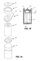
図1A及び1Bは本発明実施例の円筒形燃料セルの主成分を図示するものであり、図1Aはセルの分解図である。電極と電解質の層が交互に円筒形の集合101(ジェリイロールと呼ばれる)の中に与えられて居る。円筒形集合或はジェリイロール101は缶113或はその他の収容容器の内部に位置されている。陰性コレクタ円板103と陽性コレクタ円板105とが円筒形集合101の相対する端部に付着されている。陰性と陽性のコレクタ円板は内部端子として機能し、陰性コレクタ円板は陰極に電気的に接続し、陽性コレクタ円板は陽極に電気的に接続して居る。キャップ109と缶113とは外部端子として機能する。図示された実施例では、陰性コレクタ円板103は陰性コレクタ円板103をキャップ109に接続するためのタブ107を含んで居る。陽性コレクタ円板105は溶接或は別法によって電気的に缶113に接続されて居る。別の実施例に於いては、陰性コレクタ円板が缶に接続し、陽性コレクタ円板がキャップに接続する。
General Cell Configuration FIGS. 1A and 1B illustrate the main components of a cylindrical fuel cell according to an embodiment of the present invention, and FIG. 1A is an exploded view of the cell. Electrodes and electrolyte layers are alternately provided in a cylindrical assembly 101 (called a jelly roll). The cylindrical assembly or
陰性と陽性のコレクタ円板103、105は穿孔と共に示されて居り、これによってジェリイロールへの結合及び/或は電解質のセルの一部から他の部分への移行を容易にする。別の実施例に於いては、円板に於ける(径方向、或は周辺の)孔、溝、或はその他の構成によって、これらの結合及び/或は電解質の分布を容易にする。
Negative and
柔軟なガスケット111が、キャップ109に近く、缶113の上部の周辺に沿って備えられた周辺ビーズ115の上に設置されている。このガスケット111はキャップ109を電気的に缶113から隔離する役を果たす。実施例によっては、ガスケット111が置かれるこれらのビーズ115はポリマーが塗布されて居る。ガスケットはキャップを缶から電気的に隔離するならば、どのような材料であってもよい。この材料は高温であまり変形しないものが好ましく、ナイロンなどがその一例である。別例として好ましいのは、比較的疎水性の材料を使用することで、アルカリ性の電解液をしみこませて終局的に継ぎ目とかそれ以外の侵入口の点から漏れる力を減少させることである。濡れにくい材料の一例としてプロプロピレンがある。
A
缶或はそれ以外の収容容器が電解液で満たされた後、容器は密封されて、図1Bに示される如く、電極や電解質が環境から隔離される。ガスケットが典型的にクリンピングされる。実施例によっては、漏れを防ぐために密封剤が使用される。密封剤の適宜な例として、瀝青剤、タール 及びVERSAMID(登録商標、オハイオ州、シンシナティ在のCognisにより販売)がある。 After the can or other container is filled with electrolyte, the container is sealed to isolate the electrodes and electrolyte from the environment, as shown in FIG. 1B. The gasket is typically crimped. In some embodiments, a sealant is used to prevent leakage. Suitable examples of sealants include bitumen, tar and VERSAMID (registered trademark, sold by Cognis, Cincinnati, Ohio).
実施例によっては、セルは電解質枯渇の状態で作用するように構成されている。更に或る実施例に於いては、本発明のニッケル−亜鉛セルは電解質枯渇様式を使用するものである。かようなセルは、活性電極材料に比して、相対的に少量の電解質を有するものであり、セル内部に遊離電解液を有する浸水セルから容易に区別することが出来る。米国特許出願11/116、113("Nickel Zinc Battery Design"2005年4月26日出願)(本願に参照して組み込むものとする)で説明される如く、セルを枯渇した状態で作用することは、多くの理由により望ましいことである。一般的に、枯渇したセルとは、セル電極スタックの中の空間総体積が電解質によって占められて居ないもののことと理解されて居る。典型的な例の場合、電解質充填後の枯渇状態のセルのボイド容積は、充填前のボイドの総容積の少なくとも約10%である。 In some embodiments, the cell is configured to operate in an electrolyte depleted state. Further, in some embodiments, the nickel-zinc cell of the present invention uses an electrolyte depletion mode. Such a cell has a relatively small amount of electrolyte compared to the active electrode material and can be easily distinguished from a submerged cell having a free electrolyte within the cell. As described in US patent application 11 / 116,113 ("Nickel Zinc Battery Design" filed April 26, 2005), which is incorporated herein by reference, is acting in a depleted state of the cell. This is desirable for many reasons. In general, a depleted cell is understood to mean that the total volume of space in the cell electrode stack is not occupied by electrolyte. In a typical example, the void volume of the depleted cell after electrolyte filling is at least about 10% of the total void volume before filling.
本発明のバッテリセルは、多くの異なる形状及びサイズであり得る。例えば、本発明の円筒形セルは通常のAAA型セル、AA型セル、A型セル、C型セルなどの直径や長さでよい。或る応用面に於いては、カストマイズされたセル設計が適当となる。特別な実施例のセル直径22mmで、長さ43mmのサブC型セルのものでよい。本発明は種々の非携帯用の応用で使用される種々の大きさのセルのみならず、比較的小さい角柱のセル形で使用されることに留意されるべきである。動力機具とか芝刈り機のようなものの為のバッテリパックのプロファイルによって、バッテリセルの大きさとか形状は決定されるものである。本発明は、本発明によるニッケル−亜鉛バッテリセルを一個以上含んだバッテリパックとか、電気器具の充電放電を可能とする適宜なケーシング、接点、導電線にも関するものである。 The battery cells of the present invention can be many different shapes and sizes. For example, the cylindrical cell of the present invention may have a diameter or length such as a normal AAA type cell, AA type cell, A type cell, or C type cell. For some applications, a customized cell design may be appropriate. A special embodiment of a sub-C cell with a cell diameter of 22 mm and a length of 43 mm may be used. It should be noted that the present invention is used in a relatively small prismatic cell shape as well as various sized cells used in various non-portable applications. The size or shape of the battery cell is determined by the profile of the battery pack for a power tool or a lawn mower. The present invention also relates to a battery pack including one or more nickel-zinc battery cells according to the present invention, and appropriate casings, contacts, and conductive wires that enable charging and discharging of electric appliances.
図1A及び1Bに示された実施例は従来例のNiCdセルと極性が逆になって居り、キャップが陰性で缶が陽性となって居ることに留意されたい。従来の電力セルでは、セルの極性がキャップで陽性、缶或は容器で陰性である。即ち、セル集合体の陽極はキャップと電気的に連結し、セル集合体の陰極はセル集合体を保持する缶と電気的に連結する。図1A及び1Bに示されるものを含めて本発明の或る実施例に於いて、セルの極性は従来例のセルのものと逆である。従って、陰極はキャップと電気的に連結し、陽極は缶と電気的に連結する。本発明の或る実施例に於いては、極性が従来例のデザインと同じであり、キャップが陽性であると留意されたい。 It should be noted that the embodiment shown in FIGS. 1A and 1B is opposite in polarity to the prior art NiCd cell, with negative caps and positive cans. In conventional power cells, the polarity of the cell is positive in the cap and negative in the can or container. That is, the anode of the cell assembly is electrically connected to the cap, and the cathode of the cell assembly is electrically connected to the can holding the cell assembly. In certain embodiments of the invention, including those shown in FIGS. 1A and 1B, the polarity of the cell is the reverse of that of the prior art cell. Thus, the cathode is electrically connected to the cap and the anode is electrically connected to the can. Note that in some embodiments of the invention, the polarity is the same as the prior art design and the cap is positive.
セル缶
缶とは、最終的なセルの外側のハウジング或はケーシングとなる容器のことである。缶が陰性端子となる従来例のニッケル−カドミウムセルに於いて、これは典型的にニッケルでメッキされたスチールである。上記の如く、本発明に於いて、缶は陰性端子でも陽性端子であってもよい。缶が陰性である実施例の場合、缶材料は、亜鉛電極の電圧に対応出来る物質でコーティングされて居る限り、スチールのような、従来例のニッケル−カドミウムバッテリで使用されるような構成に似たものであってよい。例えば、陰性の缶は腐食を妨げるべく、銅のような物質でコーティングされてよい。缶が陽性でキャップが陰性の実施例の場合では、缶は従来例のニッケル−カドミウムセルで使用されるような構成に似たもの、典型的にはニッケルでメッキされたスチールでよい。
The cell can the can is that a container comprising a final outer housing or casing of the cell. In conventional nickel-cadmium cells where the can is the negative terminal, this is typically nickel plated steel. As described above, in the present invention, the can may be a negative terminal or a positive terminal. In the embodiment where the can is negative, the can material is similar in construction to that used in conventional nickel-cadmium batteries, such as steel, as long as the can material is coated with a substance that can accommodate the voltage of the zinc electrode. It may be. For example, negative cans may be coated with a material such as copper to prevent corrosion. In the case of an embodiment where the can is positive and the cap is negative, the can may be similar in construction to that used in a conventional nickel-cadmium cell, typically nickel plated steel.
或る実施例に於いては、水素再結合を補助するための物質で缶の内部をコーティングすることが出来る。水素再結合の触媒となる物質ならば、何を使用してもよい。酸化銀はその一例である。 In some embodiments, the interior of the can can be coated with a material to assist in hydrogen recombination. Any substance can be used as long as it is a catalyst for hydrogen recombination. Silver oxide is an example.
通気キャップ
セルは通常環境から密閉されたものであるが、充電や放電に際してバッテリから発生するガスを放出可能にしてもよい。典型的なニッケル−カドミウムセルの場合、約200PSIの圧力でガスを放出する。或る実施例に於いて、本発明のニッケル−亜鉛セルは、通気なしのまま、この圧力或はそれ以上の圧力(例えば300PSI位まで)で作用するように設計されて居る。これにより、セル内部で生成される酸素や水素の再結合が促進される。実施例によっては、内圧を450PSI位まで、更には600PSI位までに保つように、セルが構成されてある。その他の実施例のニッケル−亜鉛セルは、比較的低圧でガスを放出するように設計される。設計が水素及び/或は酸素ガスをセル内部で再結合させず、制御された状態での放出を促進する場合に適切である。
The vent cap cell is normally sealed from the environment, but may be capable of releasing gas generated from the battery during charging or discharging. For a typical nickel-cadmium cell, the gas is released at a pressure of about 200 PSI. In one embodiment, the nickel-zinc cell of the present invention is designed to operate at this or higher pressure (eg, up to about 300 PSI) without aeration. Thereby, recombination of oxygen and hydrogen generated inside the cell is promoted. In some embodiments, the cell is configured to maintain the internal pressure up to about 450 PSI and even up to 600 PSI. Other example nickel-zinc cells are designed to release gas at relatively low pressures. Appropriate when the design does not recombine hydrogen and / or oxygen gas inside the cell and facilitates controlled release.
図2は発明の一実施例によるキャップ201と通気機構を示す。通気機構は、好ましくはガスのみ放出し、電解質は逃さない設計とする。キャップ201は、ガスケットの上に置かれたディスク208、通気窓203、及びキャップ201の上部205とを含む。ディスク208にはガス放出用の孔207がある。通気窓203は孔207を覆い、放出されるガスによって変位される。通気窓203は通常ゴムであるが、ガスの放出が可能で高温に耐えるものならいずれの物質でもよい。正方形の通気窓が好調に作用することが見出されて居る。上部205は溶接点209に於いてディスク208に溶接されて居り、ガス放出の為の孔211を有する。溶接点209と211の図示された位置は単に例示のためであり、どこでも適切な位置であってよい。好適な実施例によれば、通気機構は疎水性でガスを浸透させる膜から成る通気カバー213を含む。通気カバー材料の例としては、微小な孔を有するポリプロピレン、微小な孔を有するポリエチレン、微小な孔を有するPTFE、微小な孔を有するFEP、微小な孔を有するフルオロポリマー、及びこれらの混合物や共重合体がある(例えば、2005年9月27日発行で、本願にあらゆる目的に対して参照して組み込まれる米国特許6949310(J.Phillips)"Leak ProofPressure Relief Valve for Secondary Batteries”を参照)。材料は耐高温でなくてはならない。
FIG. 2 shows a
或る実施例に於いては、疎水性でガスを浸透させる膜が、曲がりくねったガス放出路と共に使用される。その他の通気機構も当業者には周知であり、本発明での使用が適切である。或る実施例に於いては、水素用出口区域を提供するように、セルの構成材料が選択される。例えば、水素浸透性の重合体材料でセルのキャップやガスケットが出来てもよい。特別な一例によれば、セルのキャップの外輪部が、アクリルプラスティク或は上記の重合体の一種以上のような、水素浸透性のから出来て居る。そのような実施例では、実際の端子(キャップの中央にあり、水素浸透性の材料で囲まれて居る)のみ導電性であればよい。 In some embodiments, a hydrophobic, gas permeable membrane is used with a tortuous gas discharge path. Other venting mechanisms are well known to those skilled in the art and are suitable for use in the present invention. In some embodiments, the constituent materials of the cell are selected to provide an outlet area for hydrogen. For example, a cell cap or gasket may be made of a hydrogen permeable polymer material. According to a particular example, the outer ring of the cell cap is made of hydrogen permeable, such as acrylic plastic or one or more of the above polymers. In such an embodiment, only the actual terminal (in the center of the cap and surrounded by a hydrogen permeable material) need only be conductive.
通気キャップ及び電流コレクタ円板並びにキャリヤ下地層自身の構成の詳細は本願にあらゆる目的に対して参照して組み込まれる2006年4月25日出願のPCT/US2006/015807及び2004年8月17日出願のPCT/US2004/026859(発行WO2005/020353A3)に記載されてある。 Details of the construction of the vent cap and current collector disc and the carrier underlayer itself are incorporated by reference herein for all purposes, PCT / US2006 / 015807 filed April 25, 2006 and filed August 17, 2004. PCT / US2004 / 026859 (issued WO2005 / 020353A3).
電極−隔離層サンドイッチ構成
図3は巻かれる前の陰極−隔離部−陽極サンドイッチ構成の種々の層を示す。隔離部305は電極と電解質の間のイオン交換を可能にする一方、陰極(成分301と303)を陽極(成分307と309)から機械的に隔離するものである。陰極は電気化学的活性層301と電流コレクタ303とを含む。亜鉛陰極の電気化学的活性層301は、典型的に電気化学的活性成分として、酸化亜鉛及び/或は金属亜鉛を含む。後記の如く、層301はその他の添加剤或は亜鉛酸カルシウム、酸化ビスマス、酸化アルミニウム、酸化インジウム、ヒドロエチルセルローズのような電気化学的活性成分、及び分散剤を更に含んでも良い。
Electrode-Separator Layer Sandwich Configuration FIG. 3 shows the various layers of the cathode-isolator-anode sandwich configuration prior to winding. The
電流コレクタ303は陰極材料301と電気化学的に共存可能であるべきものである。上記の如く、電流コレクタは穿孔された金属シート、拡張された金属、泡状金属、或は連続パタンの金属シートの形体であり得る。
The
陰極に対して、隔離部305の別側にあるのが陽極である。陽極も電気化学的活性層307と電流コレクタ309を含むものである。陽極の層307は電気化学的活性材料として、水酸化ニッケル、酸化ニッケル、及び/或はオキシ水酸化ニッケルを含んでもよい。添加剤には、酸化亜鉛及び酸化コバルト或はコバルト金属が含まれてもよい。電流コレクタ309はニッケル泡状金属マトリクス或はニッケル金属シートでもよい。ニッケル泡状マトリクスが使用される場合には、マトリクスに層307が吸収されてしまうことに留意すべきである。
The anode is on the other side of the
隔離部
隔離部は、電極と電解質の間のイオン交換を許容する一方、陰極と陽極とを機械的に孤立させる役を果たすものである。隔離部は叉亜鉛の樹枝状構成を防止するものである。樹状突起とは、金属付着に於ける骨格的或は樹枝的成長パタン(樹枝的成長)を持つ結晶構造のことである。実際問題として、樹状突起はセルの寿命の間に燃料セルの導電体の中に形成されて陰極と陽極とを実質上つないでしまって短絡を起こし、よってバッテリの機能を失わせるものである。
The isolation part functions to mechanically isolate the cathode and the anode while allowing ion exchange between the electrode and the electrolyte. The isolation part prevents the forked zinc dendritic structure. Dendrites are crystal structures with a skeletal or dendritic growth pattern (dendritic growth) in metal deposition. In practice, dendrites are formed in the fuel cell conductors during the life of the cell, effectively connecting the cathode and anode, causing a short circuit and thus losing the function of the battery. .
典型的に、隔離部とは小さい孔を有するものである。此処に記載されるいくつかの実施例に於いて、隔離層は複数の層を含むものである。孔の存在及び/或は層状構成により、亜鉛の樹状突起は曲がりくねった通路を形成することになり、従って効果的に貫通することと、短絡とを防止することになる。好ましくは、多孔性隔離層のくねり度は約1.5〜10の範囲であり、より好ましくは約2〜5である。孔の平均直径は好ましくは大きくとも約0.2ミクロンで、更に好ましくは、約0.02〜0.1ミクロンの間である。孔のサイズは隔離層の内部に於いて均一であることが好ましい。特別な実施例に於いて、隔離層は多孔率が約35〜55%の間であり、多孔率が45%で孔のサイズが0.1ミクロンの好ましい材料を有するものとする。 Typically, the isolator has small holes. In some embodiments described herein, the isolation layer comprises a plurality of layers. Due to the presence of the holes and / or the layered configuration, the zinc dendrite will form a tortuous path, thus effectively preventing penetration and shorting. Preferably, the bend degree of the porous separator is in the range of about 1.5-10, more preferably about 2-5. The average diameter of the pores is preferably at most about 0.2 microns, more preferably between about 0.02 and 0.1 microns. The pore size is preferably uniform within the isolation layer. In a particular embodiment, the isolation layer should have a preferred material with a porosity between about 35-55%, a porosity of 45% and a pore size of 0.1 microns.
好ましい実施例によれば、隔離部は亜鉛の貫通を防止するバリヤ層とセルを電解質と共に浸潤状態に保ってイオン交換を可能にする浸潤層の少なくとも二層を含む(更に好ましくは只二層のみを含む)ものである。これはニッケル−カドミウムセルに於いて通常のことではなく、互いに隣接する電極間に唯一の隔離材料を使用するものである。 According to a preferred embodiment, the isolator comprises at least two layers (more preferably only two layers), a barrier layer that prevents zinc penetration and an infiltrating layer that keeps the cell infiltrated with the electrolyte and allows ion exchange. Included). This is not normal in a nickel-cadmium cell and uses a single isolation material between adjacent electrodes.
セルの作用は出来るだけ陽極を浸潤させ、陰極を比較的乾燥状態に保てば向上する。従って、或る実施例に於いては、バリヤ層は陰極に隣接し、浸潤層を陽極に隣接して位置させる。この配置により、電解層を陽極に密接させ、セルの作用が向上する。 The effect of the cell is improved if the anode is infiltrated as much as possible and the cathode is kept relatively dry. Thus, in some embodiments, the barrier layer is adjacent to the cathode and the infiltrating layer is positioned adjacent to the anode. With this arrangement, the electrolytic layer is brought into close contact with the anode, and the operation of the cell is improved.
その他の実施例に於いては、浸潤層が陰極に隣接し、バリヤ層が陽極に隣接して位置される。この配置は酸素の電解質を通って陰極への移行を容易にし、陰極での酸素の再結合に役立つ。 In other embodiments, the infiltrating layer is located adjacent to the cathode and the barrier layer is located adjacent to the anode. This arrangement facilitates the transfer of oxygen to the cathode through the electrolyte and helps recombine oxygen at the cathode.
バリヤ層は典型的に微小な孔を有する多孔性の膜である。導イオン性の微小な孔を持つ多孔性の膜ならば、いずれのものでも使用可能である。多孔率が30〜80%の間のポリオレフィンがしばしば使用されるが、孔の平均径が約0.005〜0.3ミクロンの間であることが好適である。好ましい実施例では、バリヤ層は微小な孔を持つ多孔性のポリプロピレンである。バリヤ層は典型的に厚さが約0.5〜4ミルで、より好ましくは約1.5〜4ミルの間である。 The barrier layer is typically a porous film having minute pores. Any porous membrane having fine ion-conductive pores can be used. Polyolefins with a porosity between 30 and 80% are often used, but it is preferred that the average pore diameter is between about 0.005 and 0.3 microns. In a preferred embodiment, the barrier layer is a porous polypropylene with micropores. The barrier layer is typically about 0.5-4 mils thick, more preferably between about 1.5-4 mils.
浸潤層は浸潤性が適当にある如何なる隔離層材料であってもよい。典型的に、浸潤層の多孔率は比較的高く、例えば約50〜85%の間である。例として、ナイロンを基にした浸潤性のあるポリエチレンやポリプロピレン材料のようなポリアミドが挙げられる。或る実施例に於いては、浸潤層の厚さは約1〜10ミルの間であり、好ましくは約3〜6ミルの間である。隔離層材料で、浸潤層材料として使用できるものの例としては、NKK VL100 (東京のNKK Corporation製)、Freudenberg FS2213E、Scimat 650/45(英国 Swindon のSciMAT Limited製)、及びVilene FV4365 がある。 The infiltrating layer may be any isolation layer material that is suitably invasive. Typically, the porosity of the infiltrating layer is relatively high, for example between about 50-85%. Examples include polyamides such as infiltrating polyethylene and polypropylene materials based on nylon. In some embodiments, the thickness of the infiltrating layer is between about 1-10 mils, preferably between about 3-6 mils. Examples of isolation layer materials that can be used as infiltration layer materials include NKK VL100 (manufactured by NKK Corporation, Tokyo), Freudenberg FS2213E, Scimat 650/45 (manufactured by SciMAT Limited, Swindon, UK), and Vilene FV4365.
当業者に周知のその他の隔離部材料も使用可能である。上記の如く、ナイロンを基にした材料や、微小な孔を有する多孔性ポリオレフィン(例えばポリエチレン及びポロプロピレン)はしばしば非常に好適である。 Other separator materials known to those skilled in the art can also be used. As noted above, nylon-based materials and porous polyolefins with micropores (eg, polyethylene and polypropylene) are often very suitable.
その他の実施例に於いて、亜鉛の通過を妨げ、セルを電解液で浸潤状態に保つのに、単一の隔離部材料を用いてもよい。このような単一隔離部材料としては、従来のリチウムイオンセルで使用される隔離部であって、ニッケル−亜鉛セル用に変更させたものでよい。例えば、リチウムイオン型隔離部にゲルを満たして、その浸潤性を向上させることが出来る。その一例としてはオレゴン州LebanonのEntek Membrane LLCの製品であるポリエチレンTeklon材料が挙げられる。この材料は厚さ20ミクロンで、多孔率は約40%である。ゲルは隔離部材料に直接、或は亜鉛電極に加えるような間接法で付与される。後記の如く、ゲルの電解質は或る実施例に於いて使用される。 In other embodiments, a single separator material may be used to prevent the passage of zinc and keep the cell infiltrated with electrolyte. Such a single isolation material may be an isolation used in a conventional lithium ion cell and modified for a nickel-zinc cell. For example, the lithium ion type isolation part can be filled with gel to improve the infiltration property. An example is polyethylene Teklon material, a product of Entek Membrane LLC of Lebanon, Oregon. This material is 20 microns thick and has a porosity of about 40%. The gel is applied directly to the separator material or by an indirect method such as adding to the zinc electrode. As described below, gel electrolytes are used in some embodiments.
実施例によっては、陽極/陰極構成に組み込まれる前に、界面活性剤が隔離部に施されてもよい。これで浸潤性を向上させ、電流の均一性を増加させることが出来る。特別な実施例に於いて、隔離部は先ずミシガン州MidlandのDow Chemical CorporationのTriton界面活性剤(例えばX100)の約0.5〜5%溶液で処理される。界面活性剤との接触時間、乾燥時間、界面活性剤の種類及び界面活性剤の濃度など、すべて処理の効率に関係するものである。数時間低濃度の溶液に浸潤し、次いで空気で乾燥させることで優秀な結果が得られる。追加的にメタノールのようなその他の溶媒を使用することで界面活性剤の摂取が加速される。 In some embodiments, a surfactant may be applied to the separator before being incorporated into the anode / cathode configuration. This improves the infiltration and increases the current uniformity. In a specific embodiment, the separator is first treated with an approximately 0.5-5% solution of Triton surfactant (eg, X100) from Dow Chemical Corporation, Midland, Michigan. The contact time with the surfactant, the drying time, the type of surfactant and the concentration of the surfactant all relate to the efficiency of the treatment. Excellent results are obtained by infiltrating a low concentration solution for several hours and then drying with air. In addition, the use of other solvents such as methanol accelerates the uptake of the surfactant.
微小な孔を有するポリプロピレンを浸潤性にする別法とは、特種な親水性の化学基を重合体の表面に放射線グラフトすることである。このような方法の一つが、Shanghai Institute of Applied Physics, Chinese Academy of SciencesのShanghai Shilong Hi−Tech Co, Ltd.によって使用されて居る。この場合、活性化プロセスはコバルト60の放射源を使用して行われて居る。 Another way to make polypropylene with micropores invasive is to radiation graft a special hydrophilic chemical group onto the surface of the polymer. One such method is described by Shanhai Institute of Applied Physics, China Academy of Sciences, Shanghai Hai-Hi Co., Ltd. Used by. In this case, the activation process has been performed using a cobalt 60 radiation source.
電極/隔離部のデザインについて更に考慮すべきことは、隔離部を(例えば図2に示す如く)電極や電流コレクタシートのように略同じ厚さの単一層として提供するか、或は片方或は両方の電極を隔離部の中につめるかと言うことである。後者の例での隔離部は、電極シートの中の一枚用の「袋」として作用し、効果的に電極層を包み込むものである。或る実施例に於いては、陰極を隔離部に包み込むことが、樹状突起の生成防止に役立つ。しかし、叉別の実施例では、電極を包み込まずに、バリヤ層を使用するだけで、樹状突起の貫通に対する保護に十分である。 Further considerations for electrode / isolator design include providing the separator as a single layer of approximately the same thickness, such as an electrode or current collector sheet (eg, as shown in FIG. 2), or The idea is to pack both electrodes in the isolator. The isolation part in the latter example acts as a “bag” for one sheet in the electrode sheet, and effectively wraps the electrode layer. In some embodiments, wrapping the cathode in the isolation helps prevent dendrite formation. However, in another embodiment, the use of a barrier layer without enveloping the electrodes is sufficient to protect against dendritic penetration.
陽極
陽極は一般に電気化学的活性酸化或は水酸化ニッケル及び製造、電子運行、浸潤性、機械的性能などの観点から一種類以上の添加剤とを含んで居る。例えば、陽極構成として少なくとも電気化学的活性酸化或は水酸化ニッケル(例えばNi(OH)2)、酸化亜鉛、酸化コバルト(CoO)、金属コバルト、金属ニッケル及びカルボキシルメチルセルローズ(CMC)のような流制御剤を含む。金属ニッケルやコバルトは化学的純粋なものであっても、合金であってもよい。或る実施例では、陽極は一般のニッケル−カドミウムバッテリのニッケル電極製造に使用されるような構成であってもよいが、ニッケル−亜鉛バッテリシステムの為に必要な最適化が必要かも知れない。
The anode generally contains electrochemically active oxidation or nickel hydroxide and one or more additives from the standpoints of manufacturing, electronic operation, infiltration, mechanical performance, and the like. For example, at least electrochemically active oxidation or nickel hydroxide (eg Ni (OH) 2 ), zinc oxide, cobalt oxide (CoO), metallic cobalt, metallic nickel and carboxymethyl cellulose (CMC) as the anode configuration. Contains a control agent. The metallic nickel or cobalt may be chemically pure or an alloy. In some embodiments, the anode may be configured for use in the production of nickel electrodes for a typical nickel-cadmium battery, but may require the necessary optimization for a nickel-zinc battery system.
好ましくは泡状ニッケルマトリクスが電気的活性ニッケル電極材料(例えばNi(OH)2)として使用される。一例として、市売のInco Ltd.の泡状ニッケルが使用されてもよい。高い放電率を要する応用に於いては、泡状ニッケルを通ってNi(OH)2(或はその他の電気化学的活性材料)に至る拡散路が短くなくてはならない。高率の場合、イオンが泡状ニッケルを貫通するに要する時間は重要である。Ni(OH)2(或はその他の電気化学的活性材料)及びその他の電極物質で充填された泡状ニッケルを含む陽極の幅は、泡を通ってNi(OH)2に至るイオンの拡散路を短く保ちながら、Ni(OH)2のために十分な空間を提供出来るように最適化されるべきである。泡状下地層の厚さは15〜60ミルの間でよい。好もしい実施例によれば、電気化学的活性物質或はその他の電極物質で満たされた泡状ニッケルを含む陽極の厚さは約16〜24ミルの範囲である。特別な実施例では、陽極の厚さは約20ミルである。 Preferably a foamy nickel matrix is used as the electroactive nickel electrode material (eg Ni (OH) 2 ). As an example, the marketer Inco Ltd. Foamed nickel may be used. In applications that require high discharge rates, the diffusion path through the foam nickel to Ni (OH) 2 (or other electrochemically active material) must be short. For high rates, the time required for ions to penetrate the foam nickel is important. The width of the anode containing foam nickel filled with Ni (OH) 2 (or other electrochemically active material) and other electrode materials is the diffusion path of ions through the foam to Ni (OH) 2 Should be optimized so as to provide sufficient space for Ni (OH) 2 while keeping it short. The thickness of the foam base layer may be between 15 and 60 mils. According to a preferred embodiment, the thickness of the anode comprising foam nickel filled with an electrochemically active material or other electrode material is in the range of about 16-24 mils. In a particular embodiment, the anode thickness is about 20 mils.
泡状ニッケルの密度は、電気化学的活性材料が泡のボイド空間を均一的に貫通するように最適化されるべきである。好ましい実施例に於いては、密度の範囲が約300〜500g/m2の泡状ニッケルが使用される。更に好ましくは、約350〜500g/m2の範囲であり、殊に好ましい実施例では密度が約350g/m2の泡状ニッケルが使用される。電極の幅が減少するに従って、ボイド空間が十分存在するように泡の密度も小さく出来る。好ましい実施例として、密度が約350g/m2であり、厚さが約16〜18ミルの範囲にある泡状ニッケルが使用される。 The density of the foam nickel should be optimized so that the electrochemically active material penetrates uniformly through the void space of the foam. In the preferred embodiment, foam nickel having a density range of about 300-500 g / m 2 is used. More preferably, it is in the range of about 350 to 500 g / m 2 , and in a particularly preferred embodiment, foam nickel having a density of about 350 g / m 2 is used. As the electrode width decreases, the bubble density can be reduced so that there is sufficient void space. In a preferred embodiment, foam nickel having a density of about 350 g / m 2 and a thickness in the range of about 16-18 mils is used.
陰極構成
一般的に、陰極は下記の如く、導電性増加物質、腐食抑制剤、浸潤剤などの一種以上と共に、亜鉛或は亜鉛酸イオンの電気的活性源を一種以上含むものである。陰極は、その製造の時に、クーロン容量、活性亜鉛の科学的構成、多孔性、曲げ特性のような物理的、化学的、形態的特性によって特徴付けられるものである。
Cathode Construction In general, the cathode contains one or more electrically active sources of zinc or zincate ions, as well as one or more of conductivity enhancing substances, corrosion inhibitors, wetting agents, and the like as described below. The cathode is characterized by physical, chemical and morphological properties such as Coulomb capacity, active zinc scientific composition, porosity, bending properties at the time of its manufacture.
或る実施例に於いて、電気化学的活性亜鉛源は、酸化亜鉛、亜鉛酸カルシウム、金属亜鉛、及び種々な亜鉛合金から選ばれる一種以上を含む。これらの物質はいずれも製造中に供給及び/或は通常のセル周期の間に生成されるものである。特別な例として、亜鉛酸カルシウムが考慮されるが、これは例えば酸化カルシウムと酸化亜鉛とを含むペースト或はスラリーから製造出来るものである。亜鉛合金が使用される場合、実施例によっては、これにビスマス及び/或はインジウムが含まれて居てもよい。実施例によっては、百万に対して約20部未満の鉛が含まれてもよい。この構成条件を満たし、市場で入手可能な亜鉛合金として、カナダのNoranda社によるPG101がある。 In some embodiments, the electrochemically active zinc source comprises one or more selected from zinc oxide, calcium zincate, metallic zinc, and various zinc alloys. Any of these materials may be supplied during manufacture and / or produced during normal cell cycles. As a special example, calcium zincate is considered, which can be produced from a paste or slurry containing, for example, calcium oxide and zinc oxide. If a zinc alloy is used, in some embodiments this may include bismuth and / or indium. In some embodiments, less than about 20 parts lead per million may be included. An example of a zinc alloy that satisfies this structural condition and is available on the market is PG101 from Noranda, Canada.
亜鉛活性物質は粉末状、粒子状などでよい。亜鉛電極のペースト材料内部の各成分が比較的小さい粒径であることが望ましい。これは、粒子が浸透或はその他によって陽極と陰極の間の隔離層を傷害する可能性を減少する為である。 The zinc active substance may be in the form of a powder, particles or the like. It is desirable that each component in the zinc electrode paste material has a relatively small particle size. This is to reduce the possibility that the particles will permeate or otherwise damage the isolation layer between the anode and cathode.
陰極は電気化学的活性な亜鉛成分に加えて、イオン輸送や電子輸送(即ち導電性の増加)、浸潤性、多孔性、構造的完全性(即ち結合性)、ガス放出、活性材料の溶解性及びバリヤ性(例えば亜鉛の電極からの放出量減少)腐食の抑制などのプロセスを容易にしたり、影響を与えたりする一種以上の物質をも含むことが出来る。例えば、或る実施例によれば、陰極は酸化ビスマス、酸化インジウム、及び/或は酸化アルミニウムのような酸化物を含む。酸化ビスマスと酸化インジウムとは、亜鉛と反応して電極に於けるガス放出を低減する。酸化ビスマスは乾燥状陰極構成に対し、重量で約1%〜10%の間の濃度で与えられる。これで、水素と酸素の再結合を容易にすることが出来る。酸化インジウムは、乾燥状陰極構成に対し、重量で約0.05%と1%の間の濃度で存在出来る。酸化アルミニウム、乾燥状陰極構成に対し、重量で約1%と5%の間の濃度で供給されて良い。 In addition to the electrochemically active zinc component, the cathode has ion transport, electron transport (ie increased conductivity), infiltration, porosity, structural integrity (ie binding), outgassing, active material solubility It may also contain one or more substances that facilitate or affect processes such as barrier properties (eg, reduced zinc emissions) and corrosion inhibition. For example, according to some embodiments, the cathode comprises an oxide such as bismuth oxide, indium oxide, and / or aluminum oxide. Bismuth oxide and indium oxide react with zinc to reduce outgassing at the electrode. Bismuth oxide is provided at a concentration between about 1% and 10% by weight relative to the dry cathode configuration. This facilitates recombination of hydrogen and oxygen. Indium oxide can be present at a concentration between about 0.05% and 1% by weight relative to the dry cathode configuration. Aluminum oxide may be supplied at a concentration between about 1% and 5% by weight relative to the dry cathode configuration.
或る実施例によれば、電気的活性亜鉛材の耐腐食性を向上し、それによって貯蔵期間を延長させるように、一種以上の添加剤を加えてもよい。貯蔵期間は、バッテリセルが商業的に成功するか不成功に終わるかについて決定的な要素である。バッテリは本来不安定なものであるから、陰極をも含めてバッテリの成分などは、化学的に有用な形態で保存されるように努力が必要である。何週間も何ヶ月も使用しない中に、電極物質が腐食したり、その他の理由で多分に変質すれば、貯蔵期間の短い事でこの値打ちは限られてしまう。腐食抑制剤の例として、インジウム、ビスマス、鉛、錫、カルシウムなどのカチオンがある。一般的にこれらは陰極の中に塩(例えば硫化物、フッ化物など)として乾燥状陰極構成に対し、重量で約25%、典型的には10%以内の濃度で存在するものである。実施例によっては、電気的活性亜鉛材料の腐食を抑制する為、有機物を電極構成に混合してもよい。かかる抑制剤の例として、市場で入手可能な界面活性剤であるTriton及びRS600界面活性剤がある。 According to certain embodiments, one or more additives may be added to improve the corrosion resistance of the electroactive zinc material, thereby extending the shelf life. The shelf life is a decisive factor as to whether the battery cell will be commercially successful or unsuccessful. Since the battery is inherently unstable, it is necessary to make an effort to preserve the components of the battery including the cathode in a chemically useful form. If the electrode material is corroded or altered for other reasons during weeks or months of use, this value is limited by the short storage period. Examples of corrosion inhibitors include cations such as indium, bismuth, lead, tin, calcium. Generally, they are present in the cathode as a salt (eg, sulfide, fluoride, etc.) in a concentration of about 25% by weight, typically within 10%, relative to the dry cathode configuration. In some embodiments, organics may be mixed into the electrode configuration to inhibit corrosion of the electrically active zinc material. Examples of such inhibitors are Triton and RS600 surfactants, which are commercially available surfactants.
電解質内での亜鉛の溶解度を減らす為に加えられるアニオンの例として、燐酸塩、フッ酸塩、ホウ酸塩、珪酸塩、ステアリン酸塩などがある。一般的にこれらのアニオンは乾燥状陰極構成に対し重量で約5%以内の濃度で陰極内に存在してよい。これらのアニオンの中、少なくともあるものはセル周期の間に溶液中に入り、亜鉛の溶解度を減少させるものと思われて居る。これらの材料を含んだ電極構成の例は以下の特許及び特許出願に記載されて居り、これらは総て、あらゆる目的に対して参照して本願に組み込むものとする:米国特許6797433号("Negative Electrode Formulation for a Low Toxicity Zinc Electrode Having Additives with Redox Potentials Negative toZinc Potential"、発明者Jeffrey Phillips,2004年9月28日発行);米国特許6835499("Negative Electrode Formulation for a Low Toxicity Zinc Electrode Having Additives with Redox Potentials Positive to Zinc Potential",発明者Jeffrey Phillips,2004年12月28日発行);米国特許6818350("Alkaline Cells Having Low Toxicity Rechargeable Zinc Electrodes",発明者Jeffrey Phillips,2004年11月16日発行);PCT特許出願PCT/NZ02/00036(公開番号WO02/075830号、発明者 Hall,et al.2002年3月15日出願)。 Examples of anions added to reduce the solubility of zinc in the electrolyte include phosphates, fluorides, borates, silicates, stearates, and the like. Generally, these anions may be present in the cathode at a concentration within about 5% by weight relative to the dry cathode configuration. It is believed that at least some of these anions enter solution during the cell cycle and reduce zinc solubility. Examples of electrode configurations containing these materials are described in the following patents and patent applications, all of which are incorporated herein by reference for all purposes: US Pat. No. 6,797,433 (“Negative”). Electrode Formulation for a Low Toxicity Zinc Electrode Having Additives with Redox Potentials Negative toZinc Potential ", the inventors Jeffrey Phillips, 9 May 28, 2004 issue); United States Patent 6835499 (" Negative Electrode Formulation for a Low Toxicity Zinc Electrode Having Additives it Redox Potentials Positive to Zinc Potential ", Inventor Jeffrey Phillips, issued December 28, 2004; US Patent 6818350 (" Alkaline Cells Haven Low Rechargeable Eligibility Recharged " PCT patent application PCT / NZ02 / 00036 (publication number WO02 / 075830, inventor Hall, et al., Filed March 15, 2002).
浸潤性の向上の為に陰極に添加されてよい物質の例には酸化チタン、アルミナ、シリカなどがある。 Examples of substances that may be added to the cathode for improving the infiltration include titanium oxide, alumina, silica and the like.
一般的に、これらは乾燥状陰極構成に対して重量で約10%以内の濃度で付与される。かような物質については米国特許6811926号("Formulation of Zinc Negative Electrode for Rechargeable Cells Having an Alkaline Electrolyte"、発明者Jeffrey Phillips,2004年11月2日発行)に記載されてあり、この特許は本願に全体としてあらゆる目的に対して参照して組み込むものとする。 In general, they are applied at a concentration within about 10% by weight relative to the dry cathode configuration. Such a substance is described in US Pat. No. 6,811,926 (“Formation of Zinc Negative Electrophore for Rechargeable Cells Having an Alkaline Electrolyte”, published by the inventor Jeffrey Phillips, November 2, 2004). It shall be incorporated by reference for all purposes as a whole.
導電性向上の為に陰極に添加されてよい物質の例には固有の高い導電性を持ち、陰極と互換性を有する物質が挙げられる。その例としては、酸化チタンなどがある。一般的に、これらは乾燥状陰極構成に対して重量で約10%以内の濃度で付与される。厳密には、この濃度は勿論添加物の種類によって異なる。 Examples of substances that may be added to the cathode for improving conductivity include substances that have inherently high conductivity and are compatible with the cathode. Examples thereof include titanium oxide. In general, they are applied at a concentration within about 10% by weight relative to the dry cathode configuration. Strictly speaking, this concentration naturally depends on the type of additive.
結合、分散、及び/或は隔離部の代用物たることの目的として、陰極には種々の有機物が添加され得る。その例として、ヒドロキシルエチルセルローズ(HEC)、カルボキシメチルセルローズ(CMC)、遊離酸の形態のカルボキシメチルセルローズ(HCMC)、ポリテトラフルオロエチレン(PTFE)、ポリスチレンスルフォネート(PSS)、ポリビニルアルコール(PVA)、nopcospeprse分散剤(京都のSan Nopco Ltd.より入手可能)などがある。特殊例として、PSS及びPVAは浸潤性及び隔離部のような特徴を付与するために陰極のコーティングに使用される。実施例によっては、隔離部のような電極のコーティングに使用する場合、亜鉛−ニッケルセルは単一層の隔離部を使用してもよく、叉別の実施例に於いては,独立した隔離部が全然なくてもよい。 或る実施例によっては、PSSやPVAのような重合体材料は陰極内で隔離部にとって危険となる鋭い或は大きな粒子を埋め込む目的で、ペースト構成(コーティングではなく)に混入してもよい。 Various organic materials can be added to the cathode for the purpose of bonding, dispersing and / or surrogate substitutes. Examples include hydroxylethyl cellulose (HEC), carboxymethyl cellulose (CMC), carboxymethyl cellulose (HCMC) in the free acid form, polytetrafluoroethylene (PTFE), polystyrene sulfonate (PSS), polyvinyl alcohol (PVA). ), Nopcospepse dispersant (available from San Nopco Ltd., Kyoto). As a special case, PSS and PVA are used in cathode coatings to impart features such as infiltration and isolation. In some embodiments, the zinc-nickel cell may use a single layer of isolation when used to coat an electrode such as an isolation, and in other embodiments, an independent isolation may be used. Not at all. In some embodiments, polymeric materials such as PSS and PVA may be incorporated into the paste configuration (not the coating) for the purpose of embedding sharp or large particles that are dangerous for the separator in the cathode.
ここで電極構成について定義するに当たり、構成に適応すると言うことは、その製造(例えばペースト、スラリー、或は乾燥状の製造方式)の時に得られる構成のみならず、携帯用器具に出力中のように使用中の充電放電の1サイクル以上の最中或はその後に得られるものにも適応すると言うことである。 In defining the electrode configuration here, adapting to the configuration means not only the configuration obtained at the time of its manufacture (for example, paste, slurry, or dry manufacturing method) but also that it is being output to a portable instrument. It is also applicable to those obtained during or after one or more cycles of charge / discharge during use.
本発明の範囲内の種々の陽極構成は以下の文献に記載されて居り、これらの文献はすべてあらゆる目的に対して参照して本願に組み込まれるものとする:PCT公開WO02/39517(J.Phillips);PCT公開WO02/39520(J.Phillips);PCT公開WO02/39521;PCT公開WO02/39534(J.Phillips);米国特許公開2002182501号。上記文献に於ける陰極添加剤の例として、シリカ、各種アルカリ土金属のフッ化物、遷移金属、貴金属がある。 留意すべきことは、或る特種な性質を得る為に、何種もの物質を陰極に加えることが出来るが、これらの性質は陰極以外のバッテリ成分によって導入されることが出来ると言うことである。例えば、電解質内での亜鉛の溶解度を減少させる為の物質は、陰極によっても導入されるか否かを問わず、電解質或は隔離部(陰極にもまた与えられて居るか否かを問わず)の中に供給されてもよい。そのような物質の例にはリン酸塩、フッ化物、ホウ酸塩、亜鉛酸塩、ケイ酸塩、ステアリン酸塩などがある。上記された電極添加剤のその他の例で、電解質及び/或は隔離層の中に付与されてもよいものとして、インジウム、ビスマス、鉛、錫、カルシウムなどのイオンがある。 Various anode configurations within the scope of the present invention are described in the following references, all of which are incorporated herein by reference for all purposes: PCT Publication WO 02/39517 (J. Phillips PCT Publication WO 02/39520 (J. Phillips); PCT Publication WO 02/39521; PCT Publication WO 02/39534 (J. Phillips); US Patent Publication No. 20021822501. Examples of cathode additives in the above documents include silica, various alkaline earth metal fluorides, transition metals, and noble metals. It should be noted that a number of materials can be added to the cathode to obtain certain special properties, but these properties can be introduced by battery components other than the cathode. . For example, a substance for reducing the solubility of zinc in the electrolyte may or may not be introduced by the cathode or the electrolyte or separator (whether or not also provided to the cathode). ). Examples of such materials include phosphates, fluorides, borates, zincates, silicates, stearates and the like. Other examples of the electrode additive described above may include ions such as indium, bismuth, lead, tin, calcium, etc. that may be applied in the electrolyte and / or isolation layer.
負電子導通路
負電子導通路は、充電放電の期間に、電子を陰極と陰性(負)端子の間を通すバッテリ成分を含む。これら成分の中の一つはキャリヤ或は電流コレクタ下地層であり、陰極材料はその上に形成され、支持されるものである。これは本発明の主題である。円筒形のセルのデザインの場合、下地層は典型的には陰極材料、セル隔離部、及び陽極成分(電極それ自体、及び陽性電流コレクタ下地層を含む)、螺旋状に巻かれたサンドイッチ構成内に付与される。上記の如く、この構成はしばしばジェリイロールと呼ばれて居る。負電子導通路のその他の成分は、図1Aに示されて居る。これには電流コレクタディスク(往々導電性のタブが付けられている)と、陰性セル端子とが、必然ではないが、典型的に含まれて居る。図示された実施例に於いては、ディスクは陰性電流コレクタ下地層に直接接続されて居り、セル端子は直接電流コレクタディスク(しばしば導電性タブを通じて)接続されて居る。円筒形セルデザインの場合、陰性セル端子は通常キャップか缶である。
Negative Electron Conduction Path The negative electron conduction path includes a battery component that passes electrons between the cathode and the negative (negative) terminal during the period of charging and discharging. One of these components is a carrier or current collector underlayer, on which the cathode material is formed and supported. This is the subject of the present invention. For cylindrical cell designs, the underlayer is typically in the cathode material, cell separator, and anode components (including the electrode itself and the positive current collector underlayer), in a spiral wound sandwich configuration. To be granted. As mentioned above, this configuration is often called jellyroll. The other components of the negative electron conduction path are shown in FIG. 1A. This typically includes, but is not necessarily, a current collector disk (often with a conductive tab) and a negative cell terminal. In the illustrated embodiment, the disk is connected directly to the negative current collector underlayer and the cell terminals are connected directly to the current collector disk (often through a conductive tab). For a cylindrical cell design, the negative cell terminal is usually a cap or can.
負電子導通路の各成分は、その構成、電気的特性、化学的特性、幾何学的及び構造的特性などで特徴付けされることが出来る。例えば、或る実施例に於いては、通路の各要素は同じ構成(例えば、亜鉛とか亜鉛で覆われた銅)である。他の実施例に於いては、要素の中、少なくとも二つは異なった構成である。 Each component of the negative electron conduction path can be characterized by its configuration, electrical characteristics, chemical characteristics, geometric and structural characteristics, and the like. For example, in some embodiments, each element of the passageway has the same configuration (eg, zinc or copper covered with zinc). In other embodiments, at least two of the elements have different configurations.
電流コレクタ
上記の如く、本出願の主題である導電路の一要素はキャリヤ或は電流コレクタの役をも果たす陰極用下地層である。電流収集下地層は穿孔金属板、拡張金属、泡状金蔵などを含めて種々の構成形態で提供することが出来る。特種実施例に於いて、下地層は銅或は真鍮に基づく物質から成る穿孔板或は拡張金属である。或る実施例に於いて、下地層は厚さ約2〜5ミルの間の穿孔板である。或る実施例に於いて、下地層は厚さ約2〜20ミルの間の拡張金属である。別の実施例に於いて、下地層は厚さ約15〜60ミルの間の泡状金属である。或る特種例でのキャリヤは厚さ約3〜4ミルの穿孔された銅である。キャリヤ金属と陰極材料とを含めての陰極の厚さは、特種な例として約10〜24ミルである。
Current Collector As noted above, one element of the conductive path that is the subject of this application is a cathode or underlayer for the cathode that also serves as a current collector. The current collection underlayer can be provided in various configurations including a perforated metal plate, an extended metal, a foam metal warehouse, and the like. In a special embodiment, the underlayer is a perforated plate or an expanded metal made of a material based on copper or brass. In some embodiments, the underlayer is a perforated plate having a thickness of between about 2-5 mils. In some embodiments, the underlayer is an expanded metal between about 2-20 mils thick. In another embodiment, the underlayer is a foam metal between about 15-60 mils thick. The carrier in one particular example is perforated copper about 3-4 mils thick. The thickness of the cathode, including the carrier metal and the cathode material, is about 10-24 mils as a special example.
使用される銅或は真鍮に基づく電流コレクタの種類に拘らず、結果的な電流コレクタ構成として多くの異なる物理的構成が可能である。或る実施例に於いて、これは連続的平滑な箔として提供される。或る実施例に於いて、これは穿孔されたものである。円形、卵形、矩形、その他の幾何学的形状に穿孔されてよい。電気化学的活性層との物理的接触を向上させるため、或る実施例に於いては表面にパタニングを施し、或は粗面としてもよい。或る実施例に於いて、電流コレクタは厚さが例えば約2〜20ミルの拡張金属であってよい。別の実施例に於いて、電流コレクタは厚さが例えば約15〜60ミルの間の泡状金属であってよい。 Regardless of the type of current collector based on copper or brass used, many different physical configurations are possible for the resulting current collector configuration. In some embodiments, this is provided as a continuous smooth foil. In some embodiments, this is perforated. It may be perforated into a circular, oval, rectangular or other geometric shape. In some embodiments, the surface may be patterned or roughened to improve physical contact with the electrochemically active layer. In some embodiments, the current collector may be an expanded metal having a thickness of, for example, about 2-20 mils. In another embodiment, the current collector may be a foam metal having a thickness of, for example, between about 15-60 mils.
下地層の材料及び構造を選択する為の判断基準には、負電極材料、費用、(負電極材料で)コーティングの容易さ、水素発生の抑制、及び電気化学的活性電極材料と電流コレクタの間の電子輸送を容易にする能力がある。本発明の電流コレクタはこれらの基準を満たすものであり、場合によっては異なるデザインの電流コレクタより良好に作用する。 The criteria for selecting the material and structure of the underlayer include the negative electrode material, cost, ease of coating (with negative electrode material), suppression of hydrogen generation, and between the electrochemically active electrode material and the current collector. Has the ability to facilitate electron transport. The current collector of the present invention meets these criteria and in some cases works better than current collectors of different designs.
電流コレクタは一つ以上の金属間化合物及び錫と銅或は場合によって錫、銅及び亜鉛の合金で覆われた銅或は真鍮を使用する。合金及び金属間化合物は錫或は錫と亜鉛の両方でめっきされた下地層を焼成する事で形成される。焼成の間、底部下地層からの銅がめっきされた金属に拡散し、拡散した銅は負性ペーストと電気化学的に反応する。従ってこの拡散工程は腐食を促進し(即ちガスをより発生し)、バッテリ性能を悪化する。更に銅原子は錫原子と反応して焼成の間に一枚以上の金属間化合物層を境界面に形成する。形成される金属間化合物のタイプはめっきの厚さに依存する。厚さが20μインチの場合、形成される金属間化合物はない。厚さ40〜80μインチのめっきの場合、形成される金属間化合物はCu3Snである。厚さ200μインチのめっきの場合、形成される金属間化合物はCu3Sn(約5〜15%)とCu6Sn5(約85〜95%)である。
金属間化合物Cu3Snの形成が好まれ、化合物Cu6Sn5の形成はその物理的性質とめっき層構成の違いの理由で忌避されるべきものである。
The current collector uses one or more intermetallics and copper or brass covered with tin and copper or optionally an alloy of tin, copper and zinc. Alloys and intermetallic compounds are formed by firing an underlayer plated with tin or both tin and zinc. During firing, copper from the bottom underlayer diffuses into the plated metal and the diffused copper reacts electrochemically with the negative paste. Thus, this diffusion process promotes corrosion (ie, generates more gas) and degrades battery performance. Furthermore, copper atoms react with tin atoms to form one or more intermetallic compound layers at the interface during firing. The type of intermetallic compound formed depends on the thickness of the plating. When the thickness is 20 μinch, no intermetallic compound is formed. In the case of plating with a thickness of 40 to 80 μ inch, the formed intermetallic compound is Cu 3 Sn. In the case of plating with a thickness of 200 μinch, the intermetallic compounds formed are Cu 3 Sn (about 5-15%) and Cu 6 Sn 5 (about 85-95%).
The formation of the intermetallic compound Cu 3 Sn is preferred, and the formation of the compound Cu 6 Sn 5 should be avoided because of differences in its physical properties and plating layer composition.
金属間化合物Cu3Sn及び/或はCu6Sn5はめっきされた厚さに依存して形成されることが見出された。一例に於いて、錫めっきされた銅の下地層が260℃で約45分焼成され、走査電子顕微鏡(SEM)で撮像され、エネルギイ散乱X線(EDX)で解析された。種々の厚さに於ける焼成された下地層のSEM画像が図4に示される。図4Aに示されためっきされた厚さが約20μインチの場合、錫/銅合金(403)が形成された。底部下地層は層401として示され、これは全部銅である。図4Bに示される如く、めっきされた厚さが約60μインチの場合、錫/銅合金(403)及び金属間化合物Cu3Sn(405)が形成された。図4Cに示される如く、めっきされた厚さが約200μインチの場合、少量のCu3Sn(層405)のみが見られ、残りはCu6Sn5(層407)と純粋な錫(層409)であった。
It has been found that the intermetallic compounds Cu 3 Sn and / or Cu 6 Sn 5 are formed depending on the plated thickness. In one example, a tin-plated copper underlayer was baked at 260 ° C. for about 45 minutes, imaged with a scanning electron microscope (SEM), and analyzed with energy scattered X-rays (EDX). SEM images of the fired underlayer at various thicknesses are shown in FIG. When the plated thickness shown in FIG. 4A was about 20 μinches, a tin / copper alloy (403) was formed. The bottom underlayer is shown as
此処で使用される金属間化合物とは固体相で、任意的にいずれの成分とも異なる構成の一種以上の非金属要素と共に、或る原子率に於ける或いは非常に小さい成分領域の二種類以上の金属要素を含むものである。金属間化合物は金属的性質を有しても、有さなくてもよい。例えば、Cu6Sn5のような或る金属間化合物はもろくて曲がらない。その一方、合金は二種以上の要素の均一的な混合物であり、その原子比にはどの成分にも制限がなく、その中少なくとも一種は金属であり、残りの物質は金属性を有するものである。 As used herein, an intermetallic compound is a solid phase, optionally with one or more non-metallic elements of a configuration different from any component, and at least two types of component regions at a certain atomic rate or in a very small component region. Includes metal elements. The intermetallic compound may or may not have metallic properties. For example, certain intermetallic compounds such as Cu 6 Sn 5 are brittle and do not bend. On the other hand, an alloy is a uniform mixture of two or more elements, the atomic ratio is not limited to any component, at least one of which is a metal, and the remaining material is metallic. is there.
錫と亜鉛とが電気めっきされ、焼成される時、異なるめっき厚さの錫めっきと比較してめっき層の同様な構成が観察された。即ち、20μインチの厚さでは何の化合物も観察されない。めっきの厚さ40〜80μインチでは、形成される化合物はCu3Snである。めっきの厚さ200μインチでは、形成される化合物はCu3Sn(約5〜15%)とCu6Sn5(約85〜95%)とを含む。亜鉛はこれら二種の化合物の中で或る程度溶解するかも知れない。 When tin and zinc were electroplated and fired, a similar configuration of the plating layer was observed compared to tin plating with different plating thicknesses. That is, no compound is observed at a thickness of 20 μinches. For plating thicknesses of 40-80 μinches, the compound formed is Cu 3 Sn. At a plating thickness of 200 μinches, the compound formed contains Cu 3 Sn (about 5-15%) and Cu 6 Sn 5 (about 85-95%). Zinc may dissolve to some extent in these two compounds.
金属間化合物Cu3Sn及びCu6Sn5は物性が異なる。金属間化合物Cu3Snは大きくて不規則な形状である。Cu6Sn5はもろくてCu3Snより導通性が低い。上記の如く、下地層のデザインについての考慮点の一つは製造工程に対する抵抗能力である。一試験に於いてCu6Sn5はその後の電極を巻き付ける工程で割れた。割れたCu6Sn5は覆いの層を損傷し、底部下地層表面に於ける腐食反応を増加させた。製造中に下地層から分離した場合の物質はその後の工程に於いて汚染物源となる可能性がある。割れたCu6Sn5はバッテリ運行中の水素発生を増加させる可能性がある。上記の如く、通気キャップがあっても、水素の発生は望ましくない。導通性の低下はセルの作用に悪影響を及ぼす。従って、Cu6Sn5の形成は避けなければならない。 The intermetallic compounds Cu 3 Sn and Cu 6 Sn 5 have different physical properties. The intermetallic compound Cu 3 Sn has a large and irregular shape. Cu 6 Sn 5 is brittle and less conductive than Cu 3 Sn. As mentioned above, one of the considerations for the design of the underlayer is the resistance capability to the manufacturing process. In one test, Cu 6 Sn 5 cracked during the subsequent winding process of the electrode. Cracked Cu 6 Sn 5 damaged the cover layer and increased the corrosion reaction at the bottom underlayer surface. Substances that are separated from the underlying layer during manufacturing can become a source of contaminants in subsequent processes. Cracked Cu 6 Sn 5 can increase hydrogen generation during battery operation. As described above, even if there is a ventilation cap, generation of hydrogen is not desirable. The decrease in conductivity adversely affects the operation of the cell. Therefore, the formation of Cu 6 Sn 5 must be avoided.
Cu6Sn5の形成を避けるため、めっきされる厚さは小さくなくてはならない。上記の如く、金属間化合物及び合金の形成は焼成前のめっきされた厚さに影響される。しかし、めっきされた厚さが薄すぎると、下地層が腐食に対して十分保護されない可能性がある。耐腐食性に関しては、約40〜80μインチの厚さが好適であり、しかもCu6Sn5の形成を除去するものと見いだされた。好適にめっきされた錫には約60μインチの厚さ、めっきされた錫と亜鉛には約55μインチの厚さが使用されてよい。 In order to avoid the formation of Cu 6 Sn 5, the thickness to be plated must be small. As described above, the formation of intermetallic compounds and alloys is affected by the plated thickness before firing. However, if the plated thickness is too thin, the underlayer may not be adequately protected against corrosion. With regard to corrosion resistance, a thickness of about 40-80 μin is preferred and has been found to eliminate the formation of Cu 6 Sn 5 . A thickness of about 60 μinch may be used for suitably plated tin and a thickness of about 55 μinch for plated tin and zinc.
めっきされた下地層表面はマット仕上げされてよい。マット仕上げによって電気化学的活性物質のめっきされた下地層への接着が助成される。更に典型的に商業用めっき浴に使用される漂白添加剤がめっきされた層に組み込まれてもよく、めっきされた層を分解する可能性がある。漂白添加剤を含まないめっき浴を使用することにより分解なしのマット仕上げが保障される。 The plated underlayer surface may be matte finished. A matte finish aids the adhesion of the electrochemically active material to the plated underlayer. In addition, bleach additives typically used in commercial plating baths may be incorporated into the plated layer, potentially degrading the plated layer. The use of a plating bath that does not contain bleach additives ensures a matte finish without degradation.
製造工程
本発明の電流コレクタは、ニッケル−亜鉛セル製造工程の電極−隔離部サンドイッチ構造の組み立てに至るまでの一部分を示す図5のフロー図での工程によって製作されてもよい。ステップ502に於いて下地穿孔片が供される。この下地穿孔片は銅或いは真鍮のような銅合金から成るものでよい。下地層は更にビスマス、インジウム或いは鉛のような一種以上の要素を少量含んでもよい。一例に於いて、下地層は厚さが約4ミルの99.7%の銅箔である。下地層の長さ及び幅はバッテリの大きさ及び製造法によって異なってよい。(セルの高さが下地層の幅を決定し、種々の浴の大きさが下地層の幅を決定する。)下地層を試験するため、長さ6インチの細長片が使用された。別の場合には15インチの細長片が使用される。全規模の製造工程の場合には12000インチとかそれより長い片が使用されてもよい。サブCセルの製造には、1.325インチの幅でもよい。より大きなバッテリセルはより幅の広い片が必要であろう。場合によって、適当な大きさの片に電気めっきの後長手方向に切断されるならば、一個のセルに使用される幅の二倍から10倍の幅の片が使用されてもよい。
Manufacturing Process The current collector of the present invention may be manufactured by the process in the flow diagram of FIG. 5 showing a part of the nickel-zinc cell manufacturing process up to the assembly of the electrode-separator sandwich structure. In
脱脂穿孔片からは脂分及び不潔物を除去する(504)。変性アルコール、アセトン、或いはその他の有機溶媒が1から15分間穿孔片に付けられてよい。場合によって、例えば片が全然使用されて居らず、従って脂分とか不潔物のない場合には、この工程はなくてもよい。しかし、細長片の製造工程に於いては機械油のついた除去されるべき銅或いは真鍮の片が屡製造されるものである。片の脱脂工程の後、工程506に於いて、任意的に脱イオン(DI)水によって10−30分間すすがれる。
Fat and filth are removed from the degreased perforated piece (504). Denatured alcohol, acetone, or other organic solvents may be applied to the perforated pieces for 1 to 15 minutes. In some cases, this step may not be necessary, for example if no pieces are used and thus free of fat or filth. However, in the manufacturing process of strips, copper or brass strips to be removed with machine oil are produced. After the piece degreasing step,
穿孔片はアルカリ性浸潤溶液の中で電解的に浄化される(508)。電解的浄化の間、アルカリ性溶液に浸されたまま下地層の長さに沿って電流が与えられる。電解的浄化によってめっきされる表面が純潔、均一、平滑であることが保証される。15インチの片の場合、1〜3アンペア或は2アンペアの電流が与えられてよい。それより長い片の場合、電流はもっと高くあるべきものである。アルカリ性溶液のpHは約10〜13でよい。溶液はアルカリ性水酸化物、アルカリ性炭酸化物、及びアルカリ性リン酸化物を含んでもよい。例えば溶液は水酸化ナトリウム、炭酸ナトリウム、及びリン酸ナトリウム、或は酢酸ナトリウムを含んでよい。 The perforated pieces are cleaned electrolytically in an alkaline infiltration solution (508). During electrolytic cleaning, current is applied along the length of the underlying layer while immersed in an alkaline solution. Electrolytic cleaning ensures that the surface to be plated is pure, uniform and smooth. In the case of a 15 inch piece, a current of 1-3 amperes or 2 amperes may be provided. For longer strips, the current should be higher. The pH of the alkaline solution may be about 10-13. The solution may contain alkaline hydroxide, alkaline carbonate, and alkaline phosphate. For example, the solution may contain sodium hydroxide, sodium carbonate, and sodium phosphate or sodium acetate.
溶液は更に水酸化カリウム、炭酸カリウム、及びリン酸カリウム、或は水酸化、炭酸、及びリン酸ナトリウム及びカリウムの混合も含んでよい。一例に於いて、水酸化ナトリウムは約30〜60グラム/リットルの濃度で供される。炭酸ナトリウムは約40〜90グラム/リットルの濃度で供される。リン酸ナトリウムは50〜90グラム/リットルの濃度で供される。電解的浄化の後、穿孔片は工程510に於いて約10〜30秒間DI水ですすがれてよい。
The solution may further comprise potassium hydroxide, potassium carbonate, and potassium phosphate, or a mixture of hydroxide, carbonate, and sodium and potassium phosphates. In one example, sodium hydroxide is provided at a concentration of about 30-60 grams / liter. Sodium carbonate is provided at a concentration of about 40-90 grams / liter. Sodium phosphate is provided at a concentration of 50-90 grams / liter. After electrolytic cleaning, the perforated pieces may be rinsed with DI water in
更に電気めっき用に表面を準備するために、穿孔片は活性化溶液に浸されてもよい(512)。活性化溶液はpHが約1の強酸でよい。かような酸の一例として酸濃度約4〜20%の硫酸がある。例えば塩酸、硝酸のようなその他の強酸も使用可能である。例えば、穿孔片は酸濃度約4%の硫酸に約5〜10分間浸されてよい。或る実施例に於いて、pHがより高い、例えばpHが3或は4のより弱い酸が使用されてもよい。例えば、場合によって臭化水素酸が使用されてもよい。活性化溶液に浸されて、表面はより活性となり、結果として電気めっきされた層が好適に結合する。下地層表面は反射性や輝度が減少し、それ程黄色や赤色に見えなくなるかもしれない。活性化の後、穿孔片は工程514に於いて約10〜30秒間DI水ですすがれてよい。 In addition, the perforated pieces may be immersed in an activation solution to prepare the surface for electroplating (512). The activation solution may be a strong acid having a pH of about 1. An example of such an acid is sulfuric acid having an acid concentration of about 4-20%. Other strong acids such as hydrochloric acid and nitric acid can also be used. For example, the perforated pieces may be soaked in sulfuric acid having an acid concentration of about 4% for about 5-10 minutes. In some embodiments, weaker acids with higher pH, eg, pH 3 or 4, may be used. For example, hydrobromic acid may optionally be used. Soaked in the activation solution, the surface becomes more active, and as a result, the electroplated layers are suitably bonded. The surface of the underlayer is less reflective and bright and may not appear as yellow or red. After activation, the perforated pieces may be rinsed with DI water in step 514 for about 10-30 seconds.
穿孔片はめっき浴(516)の中で錫或は錫と亜鉛の両方で電気めっきされてよい。錫めっき用として、電気めっき浴は錫イオン或は亜鉛イオン源、及び電流キャリヤ源から成り、漂白剤は含まない。上記の如く、漂白剤は電気めっき層に組み込まれてしまうかも知れず、そうして劣化の原因となる。叉輝面は電気化学的活性層に良好に接着しない。浴は酸化遅延剤及び/或は耐トリーイング剤から成ってよい。トリーイングとは電気めっきされた層が例えば樹枝状のような不規則な形状に成長する現象のことである。トリーイングは好ましからぬ伝導路を生成したり、電気化学的活性物質の不均一な消耗を起こしたりするので、セルの有効寿命を短縮させることがある。この不規則な形状はバッテリの運行中に成長し、隔離部を穿孔し、好ましからぬ伝導路を生成して陰極と陽極の間の短絡を起こすことがある。不規則形状は或る局部に於いて例えば亜鉛のような或る種の粒子の濃度を増加し、電気化学的活性物質の不均一な欠乏を起こすことがある。
一例に於いて、錫イオン源は硫酸第一錫であり、電流キャリヤ源は酸であり、酸化遅延剤はスルフォン酸であり、耐トリーイング剤はナフトール、接着剤、ゼラチン、或はクレゾールである。その他の錫イオン源、例えば塩化第一錫(SnCl2)、或はメタンスルフォン酸第一錫(Sn(CH3SO3)2)が使用されてもよい。電流キャリヤ源はめっき路に十分な導電性を与えることの出来る如何なる酸であってもよい。例えば、電流キャリヤ源は密度約50〜100g/Lの硫酸、酢酸、ホウ酸、硫酸ナトリウム、或はスルファン酸(sulfamic acid)でよい。酸化遅延剤は第一錫の酸化を遅延させるためのもので、クレゾールスルフォン或はフェノールスルフォン酸でよい。その密度は約50〜100g/Lでよい。耐トリーイング剤はナフトール、ジヒドロキシジフェニルスルフォン、接着剤、ゼラチン、或はクレゾールでよい。ナフトール或はジヒドロキシジフェニルスルフォンは0.5〜10g/Lの密度で使用可能である。接着剤、ゼラチン、或はクレゾールは0.2〜12g/Lの密度で使用可能である。
The perforated pieces may be electroplated with tin or both tin and zinc in a plating bath (516). For tin plating, the electroplating bath consists of a source of tin ions or zinc ions, and a current carrier source, and does not contain bleach. As mentioned above, the bleach may be incorporated into the electroplating layer, thus causing degradation. The bright surface does not adhere well to the electrochemically active layer. The bath may consist of oxidation retardant and / or anti-treeing agent. Treeing is a phenomenon in which an electroplated layer grows into an irregular shape such as a dendritic shape. Treeing can reduce the useful life of the cell by creating undesirable conduction paths and non-uniform consumption of the electrochemically active material. This irregular shape can grow during battery operation, pierce the isolation, create an undesirable conduction path, and cause a short circuit between the cathode and anode. Irregular shapes may increase the concentration of certain particles, such as zinc, in certain local areas, resulting in a non-uniform lack of electrochemically active material.
In one example, the tin ion source is stannous sulfate, the current carrier source is acid, the oxidation retardant is sulfonic acid, and the anti-treeing agent is naphthol, an adhesive, gelatin, or cresol. . Other tin ion sources such as stannous chloride (SnCl 2 ) or stannous methanesulfonate (Sn (CH 3 SO 3 ) 2 ) may be used. The current carrier source can be any acid that can provide sufficient conductivity to the plating path. For example, the current carrier source may be sulfuric acid, acetic acid, boric acid, sodium sulfate, or sulfanic acid having a density of about 50-100 g / L. The oxidation retarder is for retarding the oxidation of stannous and may be cresol sulfone or phenol sulfonic acid. Its density may be about 50-100 g / L. The anti-treeing agent may be naphthol, dihydroxydiphenyl sulfone, adhesive, gelatin, or cresol. Naphthol or dihydroxydiphenyl sulfone can be used at a density of 0.5 to 10 g / L. Adhesive, gelatin, or cresol can be used at a density of 0.2-12 g / L.
錫と亜鉛の両方が堆積される別例に於いて、めっき浴は亜鉛イオン源をも含むものである。亜鉛イオン源の例には密度10〜100g/Lの塩化亜鉛(ZnCl2)、硫酸亜鉛(ZnSO4)、ピロリン酸亜鉛(Zn2P2O7)が含まれる。これ以外の亜鉛イオン源も適宜に使用可能である。 In another example where both tin and zinc are deposited, the plating bath also includes a zinc ion source. Examples of the zinc ion source include zinc chloride (ZnCl 2 ), zinc sulfate (ZnSO 4 ), and zinc pyrophosphate (Zn 2 P 2 O 7 ) with a density of 10 to 100 g / L. Other zinc ion sources can be used as appropriate.
厚さ約40〜80μインチの金属が、下地層の上に電気めっきされてよい。電気めっきの間、下地層の全体或は下地層の一部が浴に浸されてよい。連続的生産の環境に於いて、下地層の部分が交互に電気めっき浴に浸されてよい。一実施例に於いて、約60μインチの錫が下地層の各面の上に電気めっきされる。別例に於いては、約55μインチの錫と亜鉛が5Sn:1Znの割合で下地層の各面の上に電気めっきされる。此処に開示される如く、電気めっきの厚さが焼成工程で形成される金属間化合物を決定する。下地層を覆う電気めっきされた層は錫、錫合金、或は金属間化合物である。電気めっきされた層は更に若干量の銅が錫合金の部分として含まれてよい。電気めっきされた層の構成は勾配的であって、底部下地層に最も近い部分が銅を最も高率に含み、電気めっき浴に最も近い部分が銅を最も低率で含み或は含まないものでよい。 A metal about 40 to 80 microns thick may be electroplated on the underlayer. During electroplating, the entire underlayer or a portion of the underlayer may be immersed in the bath. In a continuous production environment, portions of the underlayer may be alternately immersed in the electroplating bath. In one embodiment, about 60 microns of tin is electroplated on each side of the underlayer. In another example, about 55 microinches of tin and zinc are electroplated on each side of the underlayer at a ratio of 5Sn: 1Zn. As disclosed herein, the thickness of electroplating determines the intermetallic compound formed in the firing process. The electroplated layer covering the underlayer is tin, a tin alloy, or an intermetallic compound. The electroplated layer may also contain some amount of copper as part of the tin alloy. The composition of the electroplated layer is gradual, with the portion closest to the bottom underlayer containing the highest percentage of copper and the portion closest to the electroplating bath containing the lowest percentage of copper. It's okay.
下地層に与えられる電流密度は予想外に下地層の試験結果に影響のあることが見出された。電気めっきされる厚さが同じでも、本発明者は下地層のガス発生速度を減少させるのに殊に有益な電流密度を発見した。錫及び錫−亜鉛めっきの両方の場合で、その電流密度は約4〜6分間に於いて40〜80A/m2である。或る実施例に於いて、錫及び錫−亜鉛めっきの両方の場合で、この電流密度は約4〜6分間に於いて40〜70、或は約60A/m2であってよい。 It has been found that the current density applied to the underlayer unexpectedly affects the underlayer test results. The inventors have discovered a current density that is particularly useful for reducing the gas generation rate of the underlayer, even though the electroplated thickness is the same. In both tin and tin-zinc plating, the current density is 40-80 A / m 2 for about 4-6 minutes. In some embodiments, for both tin and tin-zinc plating, this current density may be 40-70, or about 60 A / m 2 for about 4-6 minutes.
めっき工程は殊に室温で行われ、連続的にめっきされた細長片を製造する間、めっき浴の濾過と循環が必要かもしれない。 The plating process is performed at room temperature in particular and may require filtration and circulation of the plating bath during the production of continuously plated strips.
電気めっきに使用される陽極は元素金属の片であってよい。錫及び亜鉛のめっき用として、錫と亜鉛の合金或は錫と亜鉛の各々の片が使用されてよい。電気めっきされる物質は約75〜100重量%錫と約0〜25%重量%亜鉛であってよい。当業者ならば、これらの電気めっき浴構成及びめっき条件を変更してめっきされる錫と亜鉛の望まれる率に到達することが可能であろう。約4Sn:1Znから7Sn:1Zn或は10Sn:2Znの率でめっきされて本発明の電流コレクタを製造することが出来る。 The anode used for electroplating may be a piece of elemental metal. For tin and zinc plating, an alloy of tin and zinc or each piece of tin and zinc may be used. The material to be electroplated may be about 75-100% by weight tin and about 0-25% by weight zinc. Those skilled in the art will be able to change these electroplating bath configurations and plating conditions to reach the desired rate of tin and zinc to be plated. The current collector of the present invention can be fabricated by plating at a rate of about 4Sn: 1Zn to 7Sn: 1Zn or 10Sn: 2Zn.
電気めっきの後、めっきされた下地層はDI水、温水ですすがれ、熱で乾燥されてよい(518)。熱乾燥は形態学的変化を目的とするものではなく、単に下地層からすすぎを完全に蒸発させるためのものである。従って、与えられるのは少量の熱である。 After electroplating, the plated underlayer may be rinsed with DI water, warm water and dried with heat (518). Thermal drying is not intended for morphological changes, but merely for complete evaporation of the rinse from the underlayer. Therefore, a small amount of heat is given.
電気化学的活性物質がめっきされた下地層片に与えられてよい(520)。これら電気化学的活性物質の構造については既に記述されてある。通常ペーストの形状であり、これらの物質は下地層片の片面或いは両面に与えられる。平滑な付与が保証されるように、ローラのような機械的装置が使用されてもよい。穿孔片は或る時間の間周囲より高い温度に維持して焼成されてよい(522)。焼成により電気化学的活性物質から重合体が発生し、めっきされた下地層と金属間化合物を形成する金属の拡散を促進する。200−300℃の温度が30分から約2時間維持されてよい。一実施例に於いて、約260℃の温度が約45分間維持されてよい。 An electrochemically active material may be applied to the plated underlayer piece (520). The structure of these electrochemically active substances has already been described. Usually in the form of a paste, these materials are applied to one or both sides of the underlying layer piece. A mechanical device such as a roller may be used so that a smooth application is ensured. The perforated pieces may be fired (522) while maintaining a temperature above ambient for a period of time. Firing generates a polymer from the electrochemically active material and promotes diffusion of the metal that forms the intermetallic compound with the plated underlayer. A temperature of 200-300 ° C. may be maintained from 30 minutes to about 2 hours. In one embodiment, a temperature of about 260 ° C. may be maintained for about 45 minutes.
陰極物質は焼成された後、上記の陰極−隔離部サンドイッチ構成に組み立てられてよい(524)。陰極物質、隔離部、及び陽極は順に積み重ねられてこのサンドイッチ構成に形成される。この構成全体はローリング及びセル製造に適当な大きさの片へと裁断されてもよい。或る実施例に於いて、この裁断の工程は露出した銅或いは真鍮の縁部も焼成されるように片の焼成以前に実施されてもよい。その他の実施例に於いて、下地層はサンドイッチの組み立て前に他のセル構成を下地層の縁部によりよく接続できるように、焼成の後に切断される。 After the cathode material is fired, it may be assembled (524) into the cathode-isolator sandwich configuration described above. The cathode material, the separator, and the anode are stacked in order to form this sandwich configuration. The entire configuration may be cut into pieces of a size suitable for rolling and cell manufacturing. In some embodiments, this cutting step may be performed prior to firing the pieces so that exposed copper or brass edges are also fired. In other embodiments, the underlayer is cut after firing so that other cell configurations can be better connected to the edge of the underlayer before assembly of the sandwich.
本発明の内容が不明瞭にならないように、周知の工程については此処に詳細は記述は避けてある。亜鉛陰極の製法の詳細は2004年8月17日出願の米国特許出願10/921,062(J.Phillips)(本願に全体としてあらゆる目的に対して参照して組み込むものとする)に記載されてある。本発明はニッケル−亜鉛バッテリを例として説明されたものであるが、これは発明を限定するものではない。本発明による亜鉛を基にした下地層電流コレクタは、亜鉛電極を使用する多くのセルに於いて使用出来る。これらには、例えば、亜鉛−空気セル、亜鉛−銀セル、及び亜鉛−二酸化マンガンセルが含まれる。 In order not to obscure the contents of the present invention, details of well-known processes are not described here. Details of the method of making the zinc cathode are described in US patent application Ser. No. 10 / 921,062 (J. Phillips) filed Aug. 17, 2004, which is hereby incorporated by reference in its entirety for all purposes. is there. Although the present invention has been described with a nickel-zinc battery as an example, this is not intended to limit the invention. The zinc-based underlayer current collector according to the present invention can be used in many cells using zinc electrodes. These include, for example, zinc-air cells, zinc-silver cells, and zinc-manganese dioxide cells.
ガス発生試験結果
もっともガス発生速度を低くするデザイン及び製造条件を見出すために、電気めっきされた下地層のガス発生試験が各種の条件のもとで実施された。一試験に於いては種々の厚さに電気めっきされた下地層が比較された。ガス発生速度はめっきされ、焼成された下地層を電解質及び電気化学的活性物質を気密の壜の中へと結合し、三日間で発生するガスの量を測定して計測された。試験用の壜に加えられた物質の量はバッテリセルの相対的構成を真似して決定された。従って、ガス発生速度の結果は製造されたバッテリセル内でのものと相関するはずである。
Gas generation test results In order to find out the design and manufacturing conditions that most reduce the gas generation rate, gas generation tests of the electroplated underlayer were performed under various conditions. In one test, the underlying layers electroplated to various thicknesses were compared. The gas generation rate was measured by combining the plated and baked underlayer with electrolyte and electrochemically active material into an airtight cage and measuring the amount of gas generated in three days. The amount of material added to the test cage was determined by simulating the relative configuration of the battery cells. Thus, the gas generation rate result should correlate with that in the manufactured battery cell.
図6は試験結果を示す。ガス発生速度は三日に亘って測定され、24時間の平均ミリリットル値としてめっきされた層の厚さに対して図示した。厚さは与えられた電流とサンプル面積上の時間とから計算されたものであり、従って寄生的反応を含まない理論的な値である。これらの計算された厚さはSheffield platerを使用して測定された厚さと相関され、測定値に近いことが見出された。例えば理論的厚さの58.7μインチに対して26回の測定の平均は標準偏差を9.81μインチとして53.1であった。厚さの測定は理論的(計算による)厚さが計測値とよく相関することを示す。 FIG. 6 shows the test results. The gas evolution rate was measured over three days and illustrated against the plated layer thickness as an average milliliter value for 24 hours. The thickness is calculated from the applied current and the time on the sample area and is therefore a theoretical value that does not include parasitic reactions. These calculated thicknesses were correlated with the thicknesses measured using the Sheffield plater and found to be close to the measured values. For example, for a theoretical thickness of 58.7 μ inches, the average of 26 measurements was 53.1 with a standard deviation of 9.81 μ inches. Thickness measurement shows that the theoretical (calculated) thickness correlates well with the measured value.
ガス発生速度の図は、非常に低度の厚さの場合ガス発生速度の高いことを示した。薄い電気めっきされた層は下地層の全体を覆うことをせず、露出された下地層が反応して水素を発生するのだと信じられる。しかし錫めっきの場合約1.5μm即ち約60μインチでガス発生速度は最低であり、5Sn:1Znの割合の錫−亜鉛めっきの場合約1.4μm即ち約55μインチでガス発生速度は最低であった。金属がよけい電気めっきされるに従い、ガス発生速度は徐々に増加する。ガス発生速度の増加は金属間化合物Cu6Sn5の層の形成の増加と一致して居る。Cu6Sn5の厚い層が割れて下地層を露出し、水素を発生するものと信じられる。その代わりに、Cu6Sn5は直接水素の発生に寄与しているのかも知れない。
なお、本発明は以下のような態様で実現することもできる。
[適用例1]
ニッケル−亜鉛バッテリセル用の亜鉛電極下地層を製造する方法であって、
(a)銅を含む下地層の細長片を準備する工程、
(b)この片を電解的浄化する工程、
(c)電気めっき浴でこの片に電気めっきを施して40〜80μインチの錫を含む金属を堆積する工程とを含む方法。
[適用例2]
堆積される金属が更に亜鉛を含むものである、適用例1の方法。
[適用例3]
堆積される金属が約75〜100重量%の錫と約0〜25重量%の亜鉛を含むものである、適用例2の方法。
[適用例4]
下地層材料が更に亜鉛から成り、銅と亜鉛が真鍮合金を形成するものである、適用例1或は2の方法。
[適用例5]
電解的浄化がアルカリ性浸潤溶液の中で5〜10分の時間実施されるものである、適用例1或は2の方法。
[適用例6]
アルカリ性浸潤溶液のpHが約10〜13である、適用例5の方法。
[適用例7]
アルカリ性浸潤溶液がアルカリ性水酸化物、アルカリ性炭酸塩、及びアルカリ性リン酸塩を含むものである、適用例6の方法。
[適用例8]
更にこの片を活性化する工程から成り、この活性化工程がこの片を酸を含む活性化溶液に浸す工程を含むものである、適用例1の方法。
[適用例9]
活性化溶液のpHが約0.2〜3である、適用例8の方法。
[適用例10]
活性化溶液が酸濃度を4〜20%とする硫酸である、適用例8或は9の方法。
[適用例11]
電気めっき工程が電流密度約40〜80A/m 2 で約4〜6分間実施されるものである、適用例1の方法。
[適用例12]
電気めっき浴が錫イオン源と電流キャリヤ源から成り、漂白剤を含まないものである、適用例1或は11の方法。
[適用例13]
電気めっき浴のpHが約0.1〜3である、適用例1の方法。
[適用例14]
電気めっき浴が更に酸化遅延剤及び耐トリーイング剤を含む、適用例13の方法。
[適用例15]
錫イオン源が硫酸第一錫であり、電流キャリヤ源が酸であり、酸化遅延剤がスルフォン酸であり、耐トリーイング剤がナフトール、接着剤、ゼラチン、或はクレゾールである、適用例14の方法。
[適用例16]
電気めっき浴が錫イオン源と亜鉛イオン源と電流キャリヤ源から成り、漂白剤を含まないものである、適用例1或は2の方法。
[適用例17]
電気めっき浴が更に酸化遅延剤及び耐トリーイング剤から成り、錫イオン源が硫酸第一錫であり、亜鉛イオン源が硫酸亜鉛であり、電流キャリヤ源が酸であり、酸化遅延剤がスルフォン酸であり、耐トリーイング剤がナフトール、接着剤、ゼラチン、或はクレゾールである、適用例16の方法。
[適用例18]
更に
(a)酸化亜鉛に基づく電気化学的活性物質の層を下地層に貼る工程、
(b)めっきされた下地層及びペーストを焼成してペーストから重合体を除去し、錫及び銅の少なくとも一つの金属間化合物を形成する工程とを含む、適用例1或は8の方法。
[適用例19]
焼成する工程が下地層を約200〜300℃の温度に約30分から2時間維持する工程を含む、適用例18の方法。
[適用例20]
形成される少なくとも一つの金属間化合物がCu 3 Snである、適用例18の方法。
[適用例21]
(a)(i)銅或は真鍮の下地層と、(ii)この下地層の上の厚さ約40〜80μインチの錫或は錫/亜鉛めっきと、を含む電流コレクタ、及び
(b)酸化亜鉛に基づく電気化学的活性物質の層とを含む、陰極構成体。
[適用例22]
錫めっきが約60μインチである、適用例21の構成体。
[適用例23]
錫或は錫/亜鉛が約55μインチである、適用例21或は22の構成体。
[適用例24]
ニッケル−亜鉛バッテリセルであって、
(a)電流コレクタ及び酸化亜鉛に基づく電気化学的活性層を含む陰極層と;
(b)ニッケルを含む陽極層と;
(c)陰極層と陽極層とを隔離する隔離層と、から成り、
電流コレクタは銅或は真鍮の下地層及び錫及び銅の少なくとも一つの金属間化合物を含む金属間化合物層を含むものである、ニッケル−亜鉛バッテリセル。
[適用例25]
金属間化合物がCu 3 Snを主とし、10%以下のCu 6 Sn 5 を含むものである、適用例24のセル。
The gas generation rate diagram showed a high gas generation rate for very low thicknesses. It is believed that the thin electroplated layer does not cover the entire underlayer, and the exposed underlayer reacts to generate hydrogen. However, in the case of tin plating, the gas generation rate is lowest at about 1.5 μm, that is, about 60 μinch, and in the case of tin-zinc plating at a ratio of 5Sn: 1Zn, the gas generation rate is about 1.4 μm, that is, about 55 μinch. It was. As the metal is electroplated, the gas generation rate increases gradually. The increase in gas generation rate is consistent with the increase in formation of the intermetallic compound Cu6Sn5 layer. It is believed that a thick layer of Cu6Sn5 breaks to expose the underlayer and generate hydrogen. Instead, Cu6Sn5 may contribute directly to hydrogen generation.
In addition, this invention can also be implement | achieved in the following aspects.
[Application Example 1]
A method for producing a zinc electrode underlayer for a nickel-zinc battery cell, comprising:
(A) a step of preparing a strip of a base layer containing copper,
(B) a step of electrolytically purifying this piece;
(C) electroplating the strip with an electroplating bath to deposit a metal containing 40 to 80 microns of tin.
[Application Example 2]
The method of application example 1, wherein the deposited metal further comprises zinc.
[Application Example 3]
The method of Application Example 2, wherein the deposited metal comprises about 75-100% by weight tin and about 0-25% by weight zinc.
[Application Example 4]
The method of application example 1 or 2, wherein the underlayer material further comprises zinc, and copper and zinc form a brass alloy.
[Application Example 5]
The method of Application Example 1 or 2, wherein the electrolytic cleaning is performed in an alkaline infiltration solution for a period of 5 to 10 minutes.
[Application Example 6]
The method of application example 5, wherein the pH of the alkaline infiltration solution is about 10-13.
[Application Example 7]
The method of application example 6, wherein the alkaline infiltration solution includes an alkaline hydroxide, an alkaline carbonate, and an alkaline phosphate.
[Application Example 8]
The method of application example 1, further comprising the step of activating the piece, wherein the activating step comprises immersing the piece in an activating solution containing an acid.
[Application Example 9]
The method of application example 8, wherein the pH of the activation solution is about 0.2-3.
[Application Example 10]
The method of application example 8 or 9, wherein the activating solution is sulfuric acid with an acid concentration of 4-20%.
[Application Example 11]
The method of application example 1, wherein the electroplating step is performed at a current density of about 40-80 A / m 2 for about 4-6 minutes.
[Application Example 12]
The method of application example 1 or 11, wherein the electroplating bath comprises a tin ion source and a current carrier source and is free of bleach.
[Application Example 13]
The method of application example 1, wherein the pH of the electroplating bath is about 0.1-3.
[Application Example 14]
The method of application example 13, wherein the electroplating bath further comprises an oxidation retardant and an anti-treeing agent.
[Application Example 15]
Application Example 14 wherein the tin ion source is stannous sulfate, the current carrier source is acid, the oxidation retardant is sulfonic acid, and the anti-treeing agent is naphthol, an adhesive, gelatin, or cresol. Method.
[Application Example 16]
The method of application example 1 or 2, wherein the electroplating bath comprises a tin ion source, a zinc ion source, and a current carrier source and is free of bleach.
[Application Example 17]
The electroplating bath further comprises an oxidation retarder and an anti-treeing agent, the tin ion source is stannous sulfate, the zinc ion source is zinc sulfate, the current carrier source is acid, and the oxidation retarder is sulfonic acid. And the anti-treeing agent is naphthol, adhesive, gelatin, or cresol.
[Application Example 18]
More
(A) applying a layer of electrochemically active material based on zinc oxide to the underlayer;
(B) firing the plated underlayer and paste to remove the polymer from the paste to form at least one intermetallic compound of tin and copper.
[Application Example 19]
The method of application example 18, wherein the firing step comprises maintaining the underlayer at a temperature of about 200-300 ° C. for about 30 minutes to 2 hours.
[Application Example 20]
The method of application example 18, wherein the at least one intermetallic compound formed is Cu 3 Sn.
[Application Example 21]
A current collector comprising (a) (i) a copper or brass underlayer; and (ii) a tin or tin / zinc plating about 40-80 microns thick on the underlayer; and
(B) a cathode construction comprising a layer of electrochemically active material based on zinc oxide.
[Application Example 22]
The construct of application example 21 wherein the tin plating is approximately 60μ inches.
[Application Example 23]
The structure of Application Example 21 or 22, wherein the tin or tin / zinc is about 55 μinches.
[Application Example 24]
A nickel-zinc battery cell,
(A) a cathode layer comprising a current collector and an electrochemically active layer based on zinc oxide;
(B) an anode layer containing nickel;
(C) a separation layer that separates the cathode layer and the anode layer,
A nickel-zinc battery cell, wherein the current collector includes a copper or brass underlayer and an intermetallic layer comprising at least one intermetallic compound of tin and copper.
[Application Example 25]
The cell of application example 24, wherein the intermetallic compound is mainly composed of Cu 3 Sn and contains 10% or less of Cu 6 Sn 5 .
Claims (6)
(a)電流コレクタおよび酸化亜鉛ベースの電気化学的活性層を含む陰極層と;
(b)ニッケルを含む陽極層と;
(c)前記陰極層と前記陽極層とを隔離する隔離層と、を含み、
前記電流コレクタは、Cu 6 Sn 5 を含まず、銅あるいは真鍮の下地層およびCu3Snから構成される金属間化合物層を含むものである、ニッケル−亜鉛バッテリセル。 A nickel-zinc battery cell,
(A) a cathode layer comprising a current collector and a zinc oxide based electrochemically active layer;
(B) an anode layer containing nickel;
(C) an isolation layer that isolates the cathode layer and the anode layer;
The current collector is a nickel-zinc battery cell that does not include Cu 6 Sn 5 but includes an intermetallic compound layer composed of a copper or brass underlayer and Cu 3 Sn.
前記金属間化合物層が、
(a)前記銅あるいは真鍮の下地層上に錫を1.016ないし2.032μmの厚みでメッキをし、
(b)酸化亜鉛ベースの電気化学的活性物の層を前記銅あるいは真鍮の下地層に塗り、
(c)前記銅あるいは真鍮の下地層を焼成する、
ことにより形成される、ニッケル−亜鉛バッテリセル。 The nickel-zinc battery cell according to claim 1,
The intermetallic compound layer is
(A) plating tin with a thickness of 1.016 to 2.032 μm on the copper or brass base layer;
(B) applying a layer of zinc oxide based electrochemically active material to the copper or brass underlayer;
(C) firing the copper or brass base layer;
A nickel-zinc battery cell formed by
前記焼成は、前記銅あるいは真鍮の下地層を200ないし350℃の温度で30分間ないし2時間保持することを含む、ニッケル−亜鉛バッテリセル。 The nickel-zinc battery cell according to claim 2,
The nickel-zinc battery cell, wherein the firing includes holding the copper or brass underlayer at a temperature of 200 to 350 ° C. for 30 minutes to 2 hours.
(a)電流コレクタおよび酸化亜鉛ベースの電気化学的活性層を含む陰極層と;
(b)ニッケルを含む陽極層と;
(c)前記陰極層と前記陽極層とを隔離する隔離層と、を含み、
前記電流コレクタは、Cu 6 Sn 5 を含まず、銅あるいは真鍮の下地層およびCu3Snを含有する金属間化合物層を含むものである、ニッケル−亜鉛バッテリセル。 A nickel-zinc battery cell,
(A) a cathode layer comprising a current collector and a zinc oxide based electrochemically active layer;
(B) an anode layer containing nickel;
(C) an isolation layer that isolates the cathode layer and the anode layer;
The current collector is a nickel-zinc battery cell that does not contain Cu 6 Sn 5 but includes a copper or brass underlayer and an intermetallic compound layer containing Cu 3 Sn.
前記金属間化合物層が、
(a)前記銅あるいは真鍮の下地層上に錫を1.016ないし2.032μmの厚みでメッキをし、
(b)酸化亜鉛ベースの電気化学的活性物の層を前記銅あるいは真鍮の下地層に塗り、
(c)前記銅あるいは真鍮の下地層を焼成する、
ことにより形成される、ニッケル−亜鉛バッテリセル。 The nickel-zinc battery cell according to claim 4,
The intermetallic compound layer is
(A) plating tin with a thickness of 1.016 to 2.032 μm on the copper or brass base layer;
(B) applying a layer of zinc oxide based electrochemically active material to the copper or brass underlayer;
(C) firing the copper or brass base layer;
A nickel-zinc battery cell formed by
前記焼成は、前記銅あるいは真鍮の下地層を摂氏200ないし350℃の温度で30分間ないし2時間保持することにより行われる、ニッケル−亜鉛バッテリセル。 The nickel-zinc battery cell according to claim 5,
The nickel-zinc battery cell, wherein the firing is performed by holding the copper or brass underlayer at a temperature of 200 to 350 ° C. for 30 minutes to 2 hours.
Applications Claiming Priority (3)
| Application Number | Priority Date | Filing Date | Title |
|---|---|---|---|
| US11/868,337 US7931988B2 (en) | 2007-10-05 | 2007-10-05 | Tin and tin-zinc plated substrates to improve Ni-Zn cell performance |
| US11/868,337 | 2007-10-05 | ||
| PCT/US2008/078335 WO2009046031A1 (en) | 2007-10-05 | 2008-09-30 | Tin and tin-zinc plated substrates to improve ni-zn cell performance |
Publications (3)
| Publication Number | Publication Date |
|---|---|
| JP2010541183A JP2010541183A (en) | 2010-12-24 |
| JP2010541183A5 JP2010541183A5 (en) | 2011-11-17 |
| JP5205466B2 true JP5205466B2 (en) | 2013-06-05 |
Family
ID=40029599
Family Applications (1)
| Application Number | Title | Priority Date | Filing Date |
|---|---|---|---|
| JP2010528086A Active JP5205466B2 (en) | 2007-10-05 | 2008-09-30 | Tin and tin-zinc plated underlayer for improved performance of nickel-zinc cells |
Country Status (6)
| Country | Link |
|---|---|
| US (3) | US7931988B2 (en) |
| EP (1) | EP2215676B1 (en) |
| JP (1) | JP5205466B2 (en) |
| KR (1) | KR101571909B1 (en) |
| CN (1) | CN101442122B (en) |
| WO (1) | WO2009046031A1 (en) |
Families Citing this family (16)
| Publication number | Priority date | Publication date | Assignee | Title |
|---|---|---|---|---|
| CN101771142B (en) * | 2010-02-10 | 2012-09-19 | 力佳电源科技(深圳)有限公司 | Tab material of flexible-packaging lithium battery as well as electroplating method and application method thereof |
| KR101152670B1 (en) * | 2010-04-16 | 2012-06-15 | 서강대학교산학협력단 | Secondary Battery Containing Neutral Electrolyte Solution |
| KR101209687B1 (en) * | 2010-12-03 | 2012-12-10 | 기아자동차주식회사 | Lithium ion-sulfur battery |
| CN102263269B (en) * | 2011-06-22 | 2015-04-01 | 广东博特动力能源有限公司 | Cathode active material, inclined pull-net cathode matrix and cathode of nickel-zinc batteries and preparation method of cathode |
| DE102011080325A1 (en) * | 2011-08-03 | 2013-02-07 | Elringklinger Ag | Pressure equalization device for a housing of an electrochemical device |
| US9663868B2 (en) * | 2011-12-28 | 2017-05-30 | Mitsui Mining & Smelting Co., Ltd. | Electro-deposited copper-alloy foil and electro-deposited copper-alloy foil provided with carrier foil |
| CN102983336B (en) * | 2012-11-30 | 2016-01-20 | 宁波市鄞州精艺机电厂 | A kind of cathode current collector of alkaline manganese cell and preparation method thereof |
| CN104485460B (en) * | 2014-11-24 | 2016-08-24 | 天能电池集团(安徽)有限公司 | Grid natron treatment fluid and natron technique |
| WO2016205134A2 (en) * | 2015-06-16 | 2016-12-22 | 3M Innovative Properties Company | Plating bronze on polymer sheets |
| KR101692549B1 (en) * | 2015-06-18 | 2017-01-05 | 주식회사 비츠로셀 | NEGATIVE ELECTRODE CURRENT COLLECTOR FOR Ni-Zn FLOW BATTERY AND Ni-Zn FLOW BATTERY INCLUDING THE SAME |
| JP6589440B2 (en) * | 2015-07-30 | 2019-10-16 | 株式会社Gsユアサ | Storage battery |
| CN105140498B (en) * | 2015-08-27 | 2017-09-08 | 张家港智电芳华蓄电研究所有限公司 | A kind of liquid phase reactor preparation method of zinc load material |
| CN108336295A (en) * | 2017-12-28 | 2018-07-27 | 广州倬粤动力新能源有限公司 | The preparation method of conductive plate lotion |
| CN111206272B (en) * | 2020-02-25 | 2021-08-10 | 广州三孚新材料科技股份有限公司 | Plating solution additive and plating solution for electroplating matte tin on heterojunction cell, and preparation method and application of plating solution additive and plating solution |
| CN112216880A (en) * | 2020-09-24 | 2021-01-12 | 中国电子科技集团公司第十八研究所 | Zinc-silver reserve battery manufacturing method based on humidity control and zinc-silver reserve battery |
| CN114023964B (en) * | 2021-10-27 | 2023-03-28 | 武汉理工大学 | Composite zinc foil with zinc oxide particle protective layer and preparation method and application thereof |
Family Cites Families (49)
| Publication number | Priority date | Publication date | Assignee | Title |
|---|---|---|---|---|
| US3193858A (en) * | 1961-03-24 | 1965-07-13 | Gen Am Transport | Methods of producing strong threaded anchorages |
| FR1483598A (en) * | 1965-07-12 | 1967-09-06 | ||
| US4040916A (en) * | 1975-11-28 | 1977-08-09 | General Electric Company | Zinc plating bath and method of forming a non-dendritic zinc layer |
| JPH0317288A (en) * | 1989-06-13 | 1991-01-25 | Daicel Chem Ind Ltd | Electrolytic cleaning solution for stamper |
| US6652990B2 (en) | 1992-03-27 | 2003-11-25 | The Louis Berkman Company | Corrosion-resistant coated metal and method for making the same |
| US5489490A (en) | 1993-04-05 | 1996-02-06 | The Louis Berkman Company | Coated metal strip |
| US5597656A (en) | 1993-04-05 | 1997-01-28 | The Louis Berkman Company | Coated metal strip |
| US6794060B2 (en) | 1992-03-27 | 2004-09-21 | The Louis Berkman Company | Corrosion-resistant coated metal and method for making the same |
| US5491036A (en) | 1992-03-27 | 1996-02-13 | The Louis Berkman Company | Coated strip |
| US5401586A (en) | 1993-04-05 | 1995-03-28 | The Louis Berkman Company | Architectural material coating |
| US6861159B2 (en) | 1992-03-27 | 2005-03-01 | The Louis Berkman Company | Corrosion-resistant coated copper and method for making the same |
| US20030079811A1 (en) | 1992-03-27 | 2003-05-01 | The Louis Berkman Company, An Ohio Corporation | Corrosion-resistant coated metal and method for making the same |
| US5491035A (en) | 1992-03-27 | 1996-02-13 | The Louis Berkman Company | Coated metal strip |
| US6080497A (en) | 1992-03-27 | 2000-06-27 | The Louis Berkman Company | Corrosion-resistant coated copper metal and method for making the same |
| US6149781A (en) | 1994-01-10 | 2000-11-21 | Forand; James L. | Method and apparatus for electrochemical processing |
| US5837120A (en) | 1994-09-30 | 1998-11-17 | Electroplating Technologies, Inc. | Method and apparatus for electrochemical processing |
| JP3359164B2 (en) | 1994-10-19 | 2002-12-24 | キヤノン株式会社 | Rechargeable battery |
| CA2234101A1 (en) * | 1995-10-17 | 1997-04-24 | Yorkshire Chemicals Plc | Tin plating electrolyte compositions |
| FR2742002B1 (en) * | 1995-11-30 | 1998-02-20 | Peugeot | ELECTRIC ACCUMULATOR BATTERY PROVIDED WITH COOLING MEANS |
| EP0855752B1 (en) | 1997-01-28 | 2006-11-29 | Canon Kabushiki Kaisha | Electrode structural body, rechargeable battery provided with said electrode structural body, and process for the production of said electrode structural body and said rechargeable battery |
| US6193858B1 (en) | 1997-12-22 | 2001-02-27 | George Hradil | Spouted bed apparatus for contacting objects with a fluid |
| FR2796496A1 (en) * | 1999-07-15 | 2001-01-19 | Cit Alcatel | Zinc-based electrode for alkaline electrochemical generator with increased shelf life in primary or secondary cell versions, includes copper foam structure with steel and tin, indium or bismuth composition |
| JP3438199B2 (en) | 1999-09-10 | 2003-08-18 | 福井鋲螺株式会社 | Negative electrode current collector for alkaline batteries |
| KR100481661B1 (en) * | 2000-04-26 | 2005-04-14 | 산요덴키가부시키가이샤 | Lithium secondary battery-use electrode and lithium secondary battery |
| US6602629B1 (en) | 2000-05-24 | 2003-08-05 | Eveready Battery Company, Inc. | Zero mercury air cell |
| CA2325791A1 (en) | 2000-11-10 | 2002-05-10 | Jeffrey Phillips | Negative electrode formulation for a low toxicity zinc electrode having additives with redox potentials positive to zinc potential |
| CA2325308A1 (en) | 2000-11-10 | 2002-05-10 | Jeffrey Phillips | Negative electrode formulation for a low toxicity zinc electrode having additives with redox potentials negative to zinc potential |
| US6949310B2 (en) | 2001-03-15 | 2005-09-27 | Powergenix Systems, Inc. | Leak proof pressure relief valve for secondary batteries |
| CA2377065A1 (en) | 2001-03-15 | 2002-09-15 | Powergenix Systems Inc. | Alkaline cells having low toxicity rechargeable zinc electrodes |
| NZ510554A (en) | 2001-03-15 | 2003-08-29 | Univ Massey | Rechargeable zinc electrode comprising a zinc salt and a derivative of a fatty acid or alkyl sulfonic acid |
| JP2003157833A (en) * | 2001-11-19 | 2003-05-30 | Daiwa Kasei Kenkyusho:Kk | Negative electrode for lithium secondary battery and its manufacturing method |
| US7422823B2 (en) | 2002-04-03 | 2008-09-09 | Valence Technology, Inc. | Alkali-iron-cobalt phosphates and related electrode active materials |
| JP3729155B2 (en) * | 2002-05-27 | 2005-12-21 | ソニー株式会社 | Non-aqueous electrolyte battery and manufacturing method thereof |
| EP1369504A1 (en) | 2002-06-05 | 2003-12-10 | Hille & Müller | Metal strip for the manufacture of components for electrical connectors |
| JP3755506B2 (en) * | 2002-09-18 | 2006-03-15 | ソニー株式会社 | Anode material for secondary battery and secondary battery using the same |
| JP4162457B2 (en) * | 2002-09-20 | 2008-10-08 | 三洋電機株式会社 | Negative electrode for lithium secondary battery and lithium secondary battery |
| JP3877170B2 (en) * | 2003-03-28 | 2007-02-07 | 日立マクセル株式会社 | Non-aqueous secondary battery negative electrode, method for producing the same, and non-aqueous secondary battery using the negative electrode |
| US7507502B2 (en) * | 2003-03-28 | 2009-03-24 | Hitachi Maxell, Ltd. | Negative electrode having intermetallic compound that occludes/desorbs lithium as an active material layer on collector for non-aqueous secondary battery and non-aqueous secondary battery using the same |
| JP2005026151A (en) | 2003-07-04 | 2005-01-27 | Matsushita Electric Ind Co Ltd | Positive current collector for manganese dry battery and manganese dry battery using it |
| CN2632866Y (en) | 2003-07-17 | 2004-08-11 | 比亚迪股份有限公司 | Zinc-nickel battery |
| CN101577347B (en) | 2003-08-18 | 2012-05-30 | 鲍尔热尼系统公司 | Method for manufacturing nickel zinc batteries |
| US20060207084A1 (en) | 2004-08-17 | 2006-09-21 | Powergenix, Inc. | Method of manufacturing nickel zinc batteries |
| JP4646612B2 (en) * | 2004-12-08 | 2011-03-09 | パナソニック株式会社 | Negative electrode for nonaqueous electrolyte secondary battery, method for producing the same, and nonaqueous electrolyte secondary battery |
| CN100449823C (en) | 2005-01-28 | 2009-01-07 | 比亚迪股份有限公司 | Zinc negative pole used for secondary zinc-nickel battery and preperative method and secondary zinc-nickel battery containing the same zinc negative pole |
| CN101194390A (en) * | 2005-03-01 | 2008-06-04 | 鲍尔热尼系统公司 | Method of manufacturing nickel zinc batteries |
| JP4909989B2 (en) | 2005-04-29 | 2012-04-04 | エバレデイ バツテリ カンパニー インコーポレーテツド | Alkaline battery anode casing |
| JP2007172963A (en) * | 2005-12-21 | 2007-07-05 | Hitachi Cable Ltd | Negative electrode for lithium-ion secondary battery, and its manufacturing method |
| JP5300716B2 (en) | 2006-06-08 | 2013-09-25 | エバレデイ バツテリ カンパニー インコーポレーテツド | Tin-plated anode casing for alkaline batteries |
| US11611305B2 (en) | 2020-10-23 | 2023-03-21 | GM Global Technology Operations LLC | Bandwidth-partitioning harmonic regulation for improved acoustic behavior of an electric drive system |
-
2007
- 2007-10-05 US US11/868,337 patent/US7931988B2/en active Active
-
2008
- 2008-06-03 CN CN200810191136.XA patent/CN101442122B/en active Active
- 2008-09-30 EP EP08836600A patent/EP2215676B1/en active Active
- 2008-09-30 KR KR1020107007621A patent/KR101571909B1/en active IP Right Grant
- 2008-09-30 JP JP2010528086A patent/JP5205466B2/en active Active
- 2008-09-30 WO PCT/US2008/078335 patent/WO2009046031A1/en active Application Filing
-
2011
- 2011-03-23 US US13/069,879 patent/US8182946B2/en active Active
-
2012
- 2012-04-20 US US13/452,629 patent/US8372542B2/en active Active
Also Published As
| Publication number | Publication date |
|---|---|
| US20120205248A1 (en) | 2012-08-16 |
| US8372542B2 (en) | 2013-02-12 |
| US20090090636A1 (en) | 2009-04-09 |
| US20110168565A1 (en) | 2011-07-14 |
| WO2009046031A1 (en) | 2009-04-09 |
| KR101571909B1 (en) | 2015-11-25 |
| CN101442122A (en) | 2009-05-27 |
| US8182946B2 (en) | 2012-05-22 |
| CN101442122B (en) | 2014-03-05 |
| EP2215676A1 (en) | 2010-08-11 |
| EP2215676B1 (en) | 2012-06-27 |
| JP2010541183A (en) | 2010-12-24 |
| KR20100082776A (en) | 2010-07-19 |
| US7931988B2 (en) | 2011-04-26 |
Similar Documents
| Publication | Publication Date | Title |
|---|---|---|
| JP5205466B2 (en) | Tin and tin-zinc plated underlayer for improved performance of nickel-zinc cells | |
| KR101596516B1 (en) | - metallic zinc-based current collector | |
| KR101769630B1 (en) | Pasted zinc electrode for rechargeable zinc batteries | |
| US8043748B2 (en) | Pasted nickel hydroxide electrode for rechargeable nickel-zinc batteries | |
| EP1878072A2 (en) | Nickel zinc battery design | |
| JP2015181121A (en) | Nickel hydroxide electrode for rechargeable batteries | |
| KR20150106955A (en) | Pasted nickel hydroxide electrode and additives for rechargeable alkaline batteries | |
| JPH09274916A (en) | Alkaline storage battery | |
| WO2024043226A1 (en) | Aqueous electrolyte secondary battery | |
| JP2003297347A (en) | Alkaline zinc battery | |
| JPH02109264A (en) | Zinc electrode |
Legal Events
| Date | Code | Title | Description |
|---|---|---|---|
| A521 | Request for written amendment filed |
Free format text: JAPANESE INTERMEDIATE CODE: A523 Effective date: 20110930 |
|
| A621 | Written request for application examination |
Free format text: JAPANESE INTERMEDIATE CODE: A621 Effective date: 20110930 |
|
| A871 | Explanation of circumstances concerning accelerated examination |
Free format text: JAPANESE INTERMEDIATE CODE: A871 Effective date: 20110930 |
|
| A977 | Report on retrieval |
Free format text: JAPANESE INTERMEDIATE CODE: A971007 Effective date: 20120214 |
|
| A975 | Report on accelerated examination |
Free format text: JAPANESE INTERMEDIATE CODE: A971005 Effective date: 20120210 |
|
| A131 | Notification of reasons for refusal |
Free format text: JAPANESE INTERMEDIATE CODE: A131 Effective date: 20120221 |
|
| A521 | Request for written amendment filed |
Free format text: JAPANESE INTERMEDIATE CODE: A523 Effective date: 20120521 |
|
| A131 | Notification of reasons for refusal |
Free format text: JAPANESE INTERMEDIATE CODE: A131 Effective date: 20120626 |
|
| A601 | Written request for extension of time |
Free format text: JAPANESE INTERMEDIATE CODE: A601 Effective date: 20120925 |
|
| A602 | Written permission of extension of time |
Free format text: JAPANESE INTERMEDIATE CODE: A602 Effective date: 20121002 |
|
| A521 | Request for written amendment filed |
Free format text: JAPANESE INTERMEDIATE CODE: A523 Effective date: 20121225 |
|
| TRDD | Decision of grant or rejection written | ||
| A01 | Written decision to grant a patent or to grant a registration (utility model) |
Free format text: JAPANESE INTERMEDIATE CODE: A01 Effective date: 20130122 |
|
| A61 | First payment of annual fees (during grant procedure) |
Free format text: JAPANESE INTERMEDIATE CODE: A61 Effective date: 20130218 |
|
| R150 | Certificate of patent or registration of utility model |
Ref document number: 5205466 Country of ref document: JP Free format text: JAPANESE INTERMEDIATE CODE: R150 Free format text: JAPANESE INTERMEDIATE CODE: R150 |
|
| FPAY | Renewal fee payment (event date is renewal date of database) |
Free format text: PAYMENT UNTIL: 20160222 Year of fee payment: 3 |
|
| R250 | Receipt of annual fees |
Free format text: JAPANESE INTERMEDIATE CODE: R250 |
|
| R250 | Receipt of annual fees |
Free format text: JAPANESE INTERMEDIATE CODE: R250 |
|
| S531 | Written request for registration of change of domicile |
Free format text: JAPANESE INTERMEDIATE CODE: R313531 |
|
| S533 | Written request for registration of change of name |
Free format text: JAPANESE INTERMEDIATE CODE: R313533 |
|
| R350 | Written notification of registration of transfer |
Free format text: JAPANESE INTERMEDIATE CODE: R350 |
|
| R250 | Receipt of annual fees |
Free format text: JAPANESE INTERMEDIATE CODE: R250 |
|
| R250 | Receipt of annual fees |
Free format text: JAPANESE INTERMEDIATE CODE: R250 |
|
| R250 | Receipt of annual fees |
Free format text: JAPANESE INTERMEDIATE CODE: R250 |
|
| R250 | Receipt of annual fees |
Free format text: JAPANESE INTERMEDIATE CODE: R250 |
|
| R250 | Receipt of annual fees |
Free format text: JAPANESE INTERMEDIATE CODE: R250 |
|
| R250 | Receipt of annual fees |
Free format text: JAPANESE INTERMEDIATE CODE: R250 |
|
| R250 | Receipt of annual fees |
Free format text: JAPANESE INTERMEDIATE CODE: R250 |