JP5203192B2 - Stent / graft device and method for placement in open surgery - Google Patents
Stent / graft device and method for placement in open surgery Download PDFInfo
- Publication number
- JP5203192B2 JP5203192B2 JP2008524111A JP2008524111A JP5203192B2 JP 5203192 B2 JP5203192 B2 JP 5203192B2 JP 2008524111 A JP2008524111 A JP 2008524111A JP 2008524111 A JP2008524111 A JP 2008524111A JP 5203192 B2 JP5203192 B2 JP 5203192B2
- Authority
- JP
- Japan
- Prior art keywords
- stent
- vessel
- graft device
- graft
- sheath
- Prior art date
- Legal status (The legal status is an assumption and is not a legal conclusion. Google has not performed a legal analysis and makes no representation as to the accuracy of the status listed.)
- Active
Links
- 238000000034 method Methods 0.000 title abstract description 11
- 238000001356 surgical procedure Methods 0.000 title description 5
- 239000000463 material Substances 0.000 claims description 24
- 230000006378 damage Effects 0.000 abstract description 4
- 230000005012 migration Effects 0.000 abstract 1
- 238000013508 migration Methods 0.000 abstract 1
- 208000014674 injury Diseases 0.000 description 17
- 230000008733 trauma Effects 0.000 description 14
- 210000004204 blood vessel Anatomy 0.000 description 12
- 230000007246 mechanism Effects 0.000 description 10
- 230000002792 vascular Effects 0.000 description 10
- 210000004876 tela submucosa Anatomy 0.000 description 7
- 239000000203 mixture Substances 0.000 description 6
- 239000004744 fabric Substances 0.000 description 5
- 208000024248 Vascular System injury Diseases 0.000 description 4
- 208000012339 Vascular injury Diseases 0.000 description 4
- 239000003814 drug Substances 0.000 description 4
- 230000000472 traumatic effect Effects 0.000 description 4
- 238000011282 treatment Methods 0.000 description 4
- 102000008186 Collagen Human genes 0.000 description 3
- 108010035532 Collagen Proteins 0.000 description 3
- 239000004037 angiogenesis inhibitor Substances 0.000 description 3
- 239000012867 bioactive agent Substances 0.000 description 3
- 239000003795 chemical substances by application Substances 0.000 description 3
- 229920001436 collagen Polymers 0.000 description 3
- 210000003414 extremity Anatomy 0.000 description 3
- 208000024891 symptom Diseases 0.000 description 3
- 108010037362 Extracellular Matrix Proteins Proteins 0.000 description 2
- 102000010834 Extracellular Matrix Proteins Human genes 0.000 description 2
- 229940121369 angiogenesis inhibitor Drugs 0.000 description 2
- 210000001367 artery Anatomy 0.000 description 2
- 239000008280 blood Substances 0.000 description 2
- 210000004369 blood Anatomy 0.000 description 2
- 238000000576 coating method Methods 0.000 description 2
- 206010010121 compartment syndrome Diseases 0.000 description 2
- 230000034994 death Effects 0.000 description 2
- 229940079593 drug Drugs 0.000 description 2
- 229920000295 expanded polytetrafluoroethylene Polymers 0.000 description 2
- 210000002744 extracellular matrix Anatomy 0.000 description 2
- 230000006870 function Effects 0.000 description 2
- 229910052751 metal Inorganic materials 0.000 description 2
- 239000002184 metal Substances 0.000 description 2
- 229910001092 metal group alloy Inorganic materials 0.000 description 2
- 230000004048 modification Effects 0.000 description 2
- 238000012986 modification Methods 0.000 description 2
- 229940124597 therapeutic agent Drugs 0.000 description 2
- 230000008736 traumatic injury Effects 0.000 description 2
- 210000003462 vein Anatomy 0.000 description 2
- 241000251468 Actinopterygii Species 0.000 description 1
- 206010002329 Aneurysm Diseases 0.000 description 1
- 229920004934 Dacron® Polymers 0.000 description 1
- 229920000544 Gore-Tex Polymers 0.000 description 1
- 239000004677 Nylon Substances 0.000 description 1
- 206010030113 Oedema Diseases 0.000 description 1
- 239000004952 Polyamide Substances 0.000 description 1
- 208000006011 Stroke Diseases 0.000 description 1
- 208000007536 Thrombosis Diseases 0.000 description 1
- RTAQQCXQSZGOHL-UHFFFAOYSA-N Titanium Chemical compound [Ti] RTAQQCXQSZGOHL-UHFFFAOYSA-N 0.000 description 1
- 208000027418 Wounds and injury Diseases 0.000 description 1
- 208000002223 abdominal aortic aneurysm Diseases 0.000 description 1
- 238000004873 anchoring Methods 0.000 description 1
- 230000002491 angiogenic effect Effects 0.000 description 1
- 239000002260 anti-inflammatory agent Substances 0.000 description 1
- 229940121363 anti-inflammatory agent Drugs 0.000 description 1
- 230000002927 anti-mitotic effect Effects 0.000 description 1
- 239000003146 anticoagulant agent Substances 0.000 description 1
- 229940127219 anticoagulant drug Drugs 0.000 description 1
- 239000003080 antimitotic agent Substances 0.000 description 1
- 239000002246 antineoplastic agent Substances 0.000 description 1
- 239000003443 antiviral agent Substances 0.000 description 1
- 208000007474 aortic aneurysm Diseases 0.000 description 1
- 210000002469 basement membrane Anatomy 0.000 description 1
- 230000003115 biocidal effect Effects 0.000 description 1
- 239000000560 biocompatible material Substances 0.000 description 1
- 230000004071 biological effect Effects 0.000 description 1
- 230000015572 biosynthetic process Effects 0.000 description 1
- 230000017531 blood circulation Effects 0.000 description 1
- 239000002775 capsule Substances 0.000 description 1
- 230000022131 cell cycle Effects 0.000 description 1
- 230000004709 cell invasion Effects 0.000 description 1
- 239000011248 coating agent Substances 0.000 description 1
- 238000002059 diagnostic imaging Methods 0.000 description 1
- 210000001951 dura mater Anatomy 0.000 description 1
- 230000002500 effect on skin Effects 0.000 description 1
- 230000000694 effects Effects 0.000 description 1
- 229940011871 estrogen Drugs 0.000 description 1
- 239000000262 estrogen Substances 0.000 description 1
- 210000003195 fascia Anatomy 0.000 description 1
- 238000009472 formulation Methods 0.000 description 1
- 239000012634 fragment Substances 0.000 description 1
- 230000023597 hemostasis Effects 0.000 description 1
- 230000002439 hemostatic effect Effects 0.000 description 1
- 239000005556 hormone Substances 0.000 description 1
- 229940088597 hormone Drugs 0.000 description 1
- 238000003384 imaging method Methods 0.000 description 1
- 230000001771 impaired effect Effects 0.000 description 1
- 238000002513 implantation Methods 0.000 description 1
- 238000007373 indentation Methods 0.000 description 1
- 238000003780 insertion Methods 0.000 description 1
- 230000037431 insertion Effects 0.000 description 1
- 230000000968 intestinal effect Effects 0.000 description 1
- 230000033001 locomotion Effects 0.000 description 1
- 238000002595 magnetic resonance imaging Methods 0.000 description 1
- 239000011159 matrix material Substances 0.000 description 1
- 230000004220 muscle function Effects 0.000 description 1
- 206010028320 muscle necrosis Diseases 0.000 description 1
- 230000007658 neurological function Effects 0.000 description 1
- HLXZNVUGXRDIFK-UHFFFAOYSA-N nickel titanium Chemical compound [Ti].[Ti].[Ti].[Ti].[Ti].[Ti].[Ti].[Ti].[Ti].[Ti].[Ti].[Ni].[Ni].[Ni].[Ni].[Ni].[Ni].[Ni].[Ni].[Ni].[Ni].[Ni].[Ni].[Ni].[Ni] HLXZNVUGXRDIFK-UHFFFAOYSA-N 0.000 description 1
- 229910001000 nickel titanium Inorganic materials 0.000 description 1
- 229920001778 nylon Polymers 0.000 description 1
- 210000003516 pericardium Anatomy 0.000 description 1
- 210000004303 peritoneum Anatomy 0.000 description 1
- 229920002647 polyamide Polymers 0.000 description 1
- 229920000728 polyester Polymers 0.000 description 1
- 229920000642 polymer Polymers 0.000 description 1
- 229920001296 polysiloxane Polymers 0.000 description 1
- 229920002635 polyurethane Polymers 0.000 description 1
- 239000004814 polyurethane Substances 0.000 description 1
- 230000001737 promoting effect Effects 0.000 description 1
- 108090000623 proteins and genes Proteins 0.000 description 1
- 150000003839 salts Chemical class 0.000 description 1
- 239000012781 shape memory material Substances 0.000 description 1
- 210000000813 small intestine Anatomy 0.000 description 1
- 239000010935 stainless steel Substances 0.000 description 1
- 229910001220 stainless steel Inorganic materials 0.000 description 1
- 210000002784 stomach Anatomy 0.000 description 1
- 239000010936 titanium Substances 0.000 description 1
- 229910052719 titanium Inorganic materials 0.000 description 1
- 210000000689 upper leg Anatomy 0.000 description 1
Images


Classifications
-
- A—HUMAN NECESSITIES
- A61—MEDICAL OR VETERINARY SCIENCE; HYGIENE
- A61F—FILTERS IMPLANTABLE INTO BLOOD VESSELS; PROSTHESES; DEVICES PROVIDING PATENCY TO, OR PREVENTING COLLAPSING OF, TUBULAR STRUCTURES OF THE BODY, e.g. STENTS; ORTHOPAEDIC, NURSING OR CONTRACEPTIVE DEVICES; FOMENTATION; TREATMENT OR PROTECTION OF EYES OR EARS; BANDAGES, DRESSINGS OR ABSORBENT PADS; FIRST-AID KITS
- A61F2/00—Filters implantable into blood vessels; Prostheses, i.e. artificial substitutes or replacements for parts of the body; Appliances for connecting them with the body; Devices providing patency to, or preventing collapsing of, tubular structures of the body, e.g. stents
- A61F2/02—Prostheses implantable into the body
- A61F2/04—Hollow or tubular parts of organs, e.g. bladders, tracheae, bronchi or bile ducts
- A61F2/06—Blood vessels
- A61F2/07—Stent-grafts
-
- A—HUMAN NECESSITIES
- A61—MEDICAL OR VETERINARY SCIENCE; HYGIENE
- A61F—FILTERS IMPLANTABLE INTO BLOOD VESSELS; PROSTHESES; DEVICES PROVIDING PATENCY TO, OR PREVENTING COLLAPSING OF, TUBULAR STRUCTURES OF THE BODY, e.g. STENTS; ORTHOPAEDIC, NURSING OR CONTRACEPTIVE DEVICES; FOMENTATION; TREATMENT OR PROTECTION OF EYES OR EARS; BANDAGES, DRESSINGS OR ABSORBENT PADS; FIRST-AID KITS
- A61F2/00—Filters implantable into blood vessels; Prostheses, i.e. artificial substitutes or replacements for parts of the body; Appliances for connecting them with the body; Devices providing patency to, or preventing collapsing of, tubular structures of the body, e.g. stents
- A61F2/82—Devices providing patency to, or preventing collapsing of, tubular structures of the body, e.g. stents
- A61F2/86—Stents in a form characterised by the wire-like elements; Stents in the form characterised by a net-like or mesh-like structure
- A61F2/89—Stents in a form characterised by the wire-like elements; Stents in the form characterised by a net-like or mesh-like structure the wire-like elements comprising two or more adjacent rings flexibly connected by separate members
-
- A—HUMAN NECESSITIES
- A61—MEDICAL OR VETERINARY SCIENCE; HYGIENE
- A61F—FILTERS IMPLANTABLE INTO BLOOD VESSELS; PROSTHESES; DEVICES PROVIDING PATENCY TO, OR PREVENTING COLLAPSING OF, TUBULAR STRUCTURES OF THE BODY, e.g. STENTS; ORTHOPAEDIC, NURSING OR CONTRACEPTIVE DEVICES; FOMENTATION; TREATMENT OR PROTECTION OF EYES OR EARS; BANDAGES, DRESSINGS OR ABSORBENT PADS; FIRST-AID KITS
- A61F2/00—Filters implantable into blood vessels; Prostheses, i.e. artificial substitutes or replacements for parts of the body; Appliances for connecting them with the body; Devices providing patency to, or preventing collapsing of, tubular structures of the body, e.g. stents
- A61F2/82—Devices providing patency to, or preventing collapsing of, tubular structures of the body, e.g. stents
- A61F2/86—Stents in a form characterised by the wire-like elements; Stents in the form characterised by a net-like or mesh-like structure
- A61F2/90—Stents in a form characterised by the wire-like elements; Stents in the form characterised by a net-like or mesh-like structure characterised by a net-like or mesh-like structure
-
- A—HUMAN NECESSITIES
- A61—MEDICAL OR VETERINARY SCIENCE; HYGIENE
- A61F—FILTERS IMPLANTABLE INTO BLOOD VESSELS; PROSTHESES; DEVICES PROVIDING PATENCY TO, OR PREVENTING COLLAPSING OF, TUBULAR STRUCTURES OF THE BODY, e.g. STENTS; ORTHOPAEDIC, NURSING OR CONTRACEPTIVE DEVICES; FOMENTATION; TREATMENT OR PROTECTION OF EYES OR EARS; BANDAGES, DRESSINGS OR ABSORBENT PADS; FIRST-AID KITS
- A61F2/00—Filters implantable into blood vessels; Prostheses, i.e. artificial substitutes or replacements for parts of the body; Appliances for connecting them with the body; Devices providing patency to, or preventing collapsing of, tubular structures of the body, e.g. stents
- A61F2/95—Instruments specially adapted for placement or removal of stents or stent-grafts
- A61F2/962—Instruments specially adapted for placement or removal of stents or stent-grafts having an outer sleeve
- A61F2/97—Instruments specially adapted for placement or removal of stents or stent-grafts having an outer sleeve the outer sleeve being splittable
-
- A—HUMAN NECESSITIES
- A61—MEDICAL OR VETERINARY SCIENCE; HYGIENE
- A61F—FILTERS IMPLANTABLE INTO BLOOD VESSELS; PROSTHESES; DEVICES PROVIDING PATENCY TO, OR PREVENTING COLLAPSING OF, TUBULAR STRUCTURES OF THE BODY, e.g. STENTS; ORTHOPAEDIC, NURSING OR CONTRACEPTIVE DEVICES; FOMENTATION; TREATMENT OR PROTECTION OF EYES OR EARS; BANDAGES, DRESSINGS OR ABSORBENT PADS; FIRST-AID KITS
- A61F2/00—Filters implantable into blood vessels; Prostheses, i.e. artificial substitutes or replacements for parts of the body; Appliances for connecting them with the body; Devices providing patency to, or preventing collapsing of, tubular structures of the body, e.g. stents
- A61F2/02—Prostheses implantable into the body
- A61F2/04—Hollow or tubular parts of organs, e.g. bladders, tracheae, bronchi or bile ducts
- A61F2/06—Blood vessels
- A61F2/064—Blood vessels with special features to facilitate anastomotic coupling
-
- A—HUMAN NECESSITIES
- A61—MEDICAL OR VETERINARY SCIENCE; HYGIENE
- A61F—FILTERS IMPLANTABLE INTO BLOOD VESSELS; PROSTHESES; DEVICES PROVIDING PATENCY TO, OR PREVENTING COLLAPSING OF, TUBULAR STRUCTURES OF THE BODY, e.g. STENTS; ORTHOPAEDIC, NURSING OR CONTRACEPTIVE DEVICES; FOMENTATION; TREATMENT OR PROTECTION OF EYES OR EARS; BANDAGES, DRESSINGS OR ABSORBENT PADS; FIRST-AID KITS
- A61F2/00—Filters implantable into blood vessels; Prostheses, i.e. artificial substitutes or replacements for parts of the body; Appliances for connecting them with the body; Devices providing patency to, or preventing collapsing of, tubular structures of the body, e.g. stents
- A61F2/02—Prostheses implantable into the body
- A61F2/04—Hollow or tubular parts of organs, e.g. bladders, tracheae, bronchi or bile ducts
- A61F2/06—Blood vessels
- A61F2/07—Stent-grafts
- A61F2002/075—Stent-grafts the stent being loosely attached to the graft material, e.g. by stitching
-
- A—HUMAN NECESSITIES
- A61—MEDICAL OR VETERINARY SCIENCE; HYGIENE
- A61F—FILTERS IMPLANTABLE INTO BLOOD VESSELS; PROSTHESES; DEVICES PROVIDING PATENCY TO, OR PREVENTING COLLAPSING OF, TUBULAR STRUCTURES OF THE BODY, e.g. STENTS; ORTHOPAEDIC, NURSING OR CONTRACEPTIVE DEVICES; FOMENTATION; TREATMENT OR PROTECTION OF EYES OR EARS; BANDAGES, DRESSINGS OR ABSORBENT PADS; FIRST-AID KITS
- A61F2/00—Filters implantable into blood vessels; Prostheses, i.e. artificial substitutes or replacements for parts of the body; Appliances for connecting them with the body; Devices providing patency to, or preventing collapsing of, tubular structures of the body, e.g. stents
- A61F2/82—Devices providing patency to, or preventing collapsing of, tubular structures of the body, e.g. stents
- A61F2/848—Devices providing patency to, or preventing collapsing of, tubular structures of the body, e.g. stents having means for fixation to the vessel wall, e.g. barbs
- A61F2002/8483—Barbs
-
- Y—GENERAL TAGGING OF NEW TECHNOLOGICAL DEVELOPMENTS; GENERAL TAGGING OF CROSS-SECTIONAL TECHNOLOGIES SPANNING OVER SEVERAL SECTIONS OF THE IPC; TECHNICAL SUBJECTS COVERED BY FORMER USPC CROSS-REFERENCE ART COLLECTIONS [XRACs] AND DIGESTS
- Y10—TECHNICAL SUBJECTS COVERED BY FORMER USPC
- Y10S—TECHNICAL SUBJECTS COVERED BY FORMER USPC CROSS-REFERENCE ART COLLECTIONS [XRACs] AND DIGESTS
- Y10S623/00—Prosthesis, i.e. artificial body members, parts thereof, or aids and accessories therefor
- Y10S623/902—Method of implanting
- Y10S623/903—Blood vessel
Abstract
Description
本発明は、概括的には、ステント及びステントグラフトの分野に、より具体的には、患者の身体脈管内に切開手術で又は「術中」に留置するためのステント・グラフト装置と方法に関する。 The present invention relates generally to the field of stents and stent grafts, and more particularly to a stent-graft device and method for incision surgery or “intraoperative” placement within a patient's body vessel.
救急医は、しばしば身体脈管に外傷性傷害を有する患者に遭遇する。血管の様な身体脈管に重大な損傷を負うと、患者は、とりわけ、四肢欠損、四肢の機能の欠損、高い脳卒中のリスク、神経機能の障害、コンパートメント症候群の様な有害な状態に曝される。脈管傷害及び血液損失が非常に深刻な場合は、死に至る。救急医が外傷に次ぐ脈管損傷に対して一般的に行う治療の例としては、止血鉗子による脈管のクランプ、バルーンタンポナーデの使用、損傷した脈管の、傷害部位又はその付近での結紮、或いは、1つ又は複数の一時的なシャントの挿入が挙げられる。 Emergency physicians often encounter patients with traumatic injury to the body vessels. Serious damage to body vessels such as blood vessels can expose patients to harmful conditions such as limb loss, loss of limb function, high risk of stroke, impaired neurological function, and compartment syndrome, among others. The If vascular injury and blood loss are very serious, death can occur. Examples of treatments that emergency physicians typically provide for vascular injury following trauma include vascular clamping with hemostatic forceps, use of balloon tamponade, ligation of damaged vessels at or near the injury site, Alternatively, one or more temporary shunts may be inserted.
血管に対する外傷性傷害の場合、一時的なシャントの使用は、血餅の形成に繋がっている。シャントは、一般的に、血流を回復させ、過度の血液損失を止める一時的な手段として配置される。この処置は、血餅を処置し除去するために、最初の止血から約36〜48時間以内に、患者を手術室へ戻すことが必要になる場合が多い。患者が安定したら(一般的には数日後)、シャントは、通常は除去され、適所に縫いこまれる布グラフト(布移植片)の様な血管グラフトに取り換えられる。損傷した管を結紮すると、筋肉の壊死、筋肉機能の喪失、浮腫、又はコンパートメント症候群になり、四肢欠損や、死に至ることもある。 In the case of traumatic injury to blood vessels, the use of temporary shunts has led to the formation of blood clots. Shunts are generally placed as a temporary means to restore blood flow and stop excessive blood loss. This procedure often requires that the patient be returned to the operating room within about 36-48 hours of the initial hemostasis in order to treat and remove the clot. When the patient is stable (generally after a few days), the shunt is usually removed and replaced with a vascular graft such as a cloth graft that is sewn in place. Ligating a damaged tube can result in muscle necrosis, loss of muscle function, edema, or compartment syndrome, leading to limb loss or death.
遭遇する脈管傷害の性質によって、シャントの使用、脈管の修復、及び/又は結紮が必要になることが多く、その様な治療は、迅速に、医師の高度な技術を以って行われる。その様な治療は、患者の治療で他の差し迫った問題が更に応急手当を必要とするときに、救急医の時間と注意を多大に占拠する。更に、必要とされる特定の技量のレベルが、一般的な救急医が有する技術を超える場合もあるので、特定の外傷性の症状が発現した場合は、特に訓練された医師の技量が必要となる。その様な医師は、脈管の外傷の様な特定の外傷を処置し、患者をその様な場合の環境下で取り得る最良の方法で安定させるよう、特別に訓練されている。 The nature of the vascular injury that is encountered often requires the use of shunts, vascular repair, and / or ligation, and such treatment is performed quickly and with the skill of a physician. . Such treatment greatly occupies the emergency physician's time and attention when other pressing issues in patient treatment require further first aid. In addition, the level of specific skills required may exceed the skills of general emergency physicians, so when specific traumatic symptoms occur, the skills of a trained physician are required. Become. Such physicians are specially trained to treat certain traumas such as vascular trauma and stabilize the patient in the best possible manner under such circumstances.
時間的に効率的で、当該外傷に手近に可能な範囲で処置し、救急医が容易に実施できる技法を使用するやり方で、脈管の外傷(動脈と静脈)を処置するシステムと方法を提供することが必要とされている。 Providing systems and methods for treating vascular trauma (arteries and veins) in a manner that is time efficient, treats as close as possible to the trauma, and uses techniques that can be easily performed by an emergency physician There is a need to do.
本発明は、身体脈管内に術中留置するためのステント・グラフト装置と方法を提供することによって、先行技術の問題に取り組んでいる。 The present invention addresses the problems of the prior art by providing a stent-graft device and method for intraoperative placement in a body vessel.
その1つの形態では、本発明は、身体脈管の損傷した部分を術中修復するための方法である。ステント・グラフト装置は、少なくとも、術中修復を受ける損傷した脈管部分の長さと同じ長さを有している。ステント・グラフト装置は、装置が、少なくとも脈管の損傷した部分の長さに亘って留置できるようなやり方で、脈管内に配置される。ステント・グラフト装置は、ステント・グラフト装置の、前記脈管内の移動が抑制されるように脈管の損傷部分で脈管と係合される。 In one form thereof, the present invention is a method for intraoperative repair of a damaged portion of a body vessel. The stent-graft device is at least as long as the length of the damaged vessel part undergoing intraoperative repair. The stent-graft device is placed within the vessel in such a manner that the device can be placed over at least the length of the damaged portion of the vessel. The stent-graft device is engaged with the vessel at the damaged portion of the vessel so that movement of the stent-graft device within the vessel is suppressed.
別の形態では、本発明は、身体脈管の損傷した部分を術中修復するためのステント・グラフト装置である。本装置は、細長い略円筒形のステント本体と、ステント本体の少なくとも一部分を覆っているグラフト材料を備えている。装置は、脈管の直径より小さい直径を有する圧縮状態から、少なくとも脈管の直径と同じ大きさの直径を有する拡張状態へ拡張可能である。装置は、脈管内に、圧縮状態で配置され、脈管と拡張状態で係合できるようになっている。 In another form, the present invention is a stent-graft device for intraoperative repair of a damaged portion of a body vessel. The device includes an elongated generally cylindrical stent body and a graft material covering at least a portion of the stent body. The device is expandable from a compressed state having a diameter smaller than the vessel diameter to an expanded state having a diameter at least as large as the vessel diameter. The device is placed in the vessel in a compressed state so that it can engage the vessel in an expanded state.
更に別の形態では、本発明は、身体脈管の損傷した部分を術中修復するためのステント・グラフト装置である。本装置は、通路が中を貫通している略円筒形の本体を備えている。本体の少なくとも1つの軸方向端部に、コネクタが配置されている。コネクタの軸方向の一端は、通路の中へと伸張し、コネクタの軸方向の他端は、前記本体から伸張している。通路の中へと伸張する軸方向端部は、端部が本体内にぴったりと入り込むような直径を有している。本体から伸張している軸方向端部は、脈管と係合するための機構を含んでいる。 In yet another form, the present invention is a stent-graft device for intraoperative repair of a damaged portion of a body vessel. The apparatus includes a substantially cylindrical body having a passage extending therethrough. A connector is disposed at at least one axial end of the main body. One end of the connector in the axial direction extends into the passage, and the other end of the connector in the axial direction extends from the body. The axial end extending into the passage has a diameter such that the end fits snugly into the body. An axial end extending from the body includes a mechanism for engaging the vessel.
本発明の原理の理解を促すために、図示の実施形態を参照してゆくが、それを説明するのに特定の用語を使用する。しかしながら、これによって本発明の範囲を制限するものではなく、図示の装置に変更及び修正を施し、図示している本発明の原理をこの他にも応用することは、本発明に関係する当業者であれば普通に想起されるものと理解されたい。 For the purposes of promoting an understanding of the principles of the invention, reference will now be made to the illustrated embodiment, and specific language will be used to describe the same. However, this does not limit the scope of the present invention, and it will be apparent to those skilled in the art to which the present invention pertains that changes and modifications can be made to the apparatus shown and other principles of the invention illustrated can be applied. Then it should be understood that it is normally recalled.
図1は、切開手術で又は術中に留置するための、本発明のステント・グラフト装置10の1つの実施形態を示している。この実施形態では、ステント・グラフト装置10は、略円筒形の本体12を備えており、円筒形の本体12は、その軸方向のいずれか一方又は両端部に配置されているコネクタ14を有している。ステント・グラフト装置10は、血管(動脈又は静脈の何れか)の様な身体脈管内に留置するのに適した寸法形状、更に具体的には、脈管の外傷部位に留置するのに適した寸法形状を有している。
FIG. 1 illustrates one embodiment of a stent-
便宜的に、本発明の装置は、ここでは「ステント・グラフト」装置と呼ぶ。装置は、従来型のステント、並びに従来型のステントグラフトとを組み合わせた特徴を有している。本発明の或る実施形態では、1つ又は複数の従来型の拡張可能なステントは、実際のステント・グラフト装置の一部を備えており、具体的には、管状グラフト材料の端部を脈管にシールする保持部材として機能する。1つの形態では、本発明の装置は、血管の様な身体脈管への損傷及び他の外傷を術中修復するのに用いられるステントグラフトを備えている。 For convenience, the device of the present invention is referred to herein as a “stent-graft” device. The device has the characteristics of combining a conventional stent as well as a conventional stent graft. In one embodiment of the present invention, one or more conventional expandable stents comprise a portion of the actual stent-graft device, specifically, the end of the tubular graft material is pulsed. It functions as a holding member that seals the tube. In one form, the device of the present invention comprises a stent graft that is used to repair intravascularly damage to body vessels such as blood vessels and other trauma.
通常、ステント・グラフト本体12は、可撓性ポリマー材料の様な中空の細長い概ね可撓性の材料を備えており、ルーメン13が中を貫通している。ステント・グラフト本体12は、シリコン、ポリウレタン、ポリアミド(ナイロン)、並びに他の可撓性の生体適合性材料の様な、医療技術では周知の従来型の材料で形成することができる。更に、本体12は、織布ポリエステル(例えば、DACRON(登録商標))及び発泡ポリテトラフルオロエチレン(ePTFE、例えば、GORETEX(登録商標))の様な既知の布グラフト材料で、又は生体再造形可能材料で形成してもよい。生体再造形可能材料は、移植に際し材料内への細胞侵入及び内方成長を許容し、促進さえする細胞外基質を提供することができる。限定するわけではないが、適した生体再造形可能材料料の例には、再構成された、又は天然由来のコラーゲン材料が含まれる。適したコラーゲン材料には、粘膜下組織、腎被膜、皮膚コラーゲン、硬膜、心膜、大腿筋膜、漿膜、腹膜、又は基底膜の様な、生物学的特性を有する細胞外基質材料(ECM)が含まれる。適した粘膜下組織材料には、例えば、小腸の粘膜下組織を含む腸の粘膜下組織、胃の粘膜下組織、膀胱の粘膜下組織、及び子宮の粘膜下組織が含まれる。
Typically, the stent-
コネクタ14は、ステント・グラフト装置10を身体脈管内に固定的に係合させるのに適していれば、どの様な形状を備えていてもよい。限定するわけではないが、図3に示している例では、コネクタ14は、細長い管状の構造を備えており、本体部分15と、本体部分15の各軸方向端部に隣接する窪み16と、コネクタの各軸方向端部の略円錐状端部17とを有している。コネクタ14は、図1に示す様に、コネクタの一端が、ステント・グラフト本体12のルーメン内に、主コネクタ本体部分15の軸方向中間点辺りまでぴったり入り込むような寸法になっているのが望ましい。最も良いのは、本体部分15の外径が、少なくとも可撓性の円筒形本体12の内径と同じ大きさであり、コネクタ14が円筒形本体12のルーメン内に密接して固定的に嵌るようになっていることである。
The
一般に、コネクタ14は、金属、金属合金、又は高強度のポリマーの様な比較的剛性の高い構造を備えており、ルーメンが中を貫通している。コネクタ14は、以下に記載する方式で、コネクタの外周回りを1つ又は複数の縫合糸で結ぶ際に、その構造的完全性を維持できるほどの強度を有している。一般的に、その組成物が縫合糸によって外周上に圧力が加えられた際に過度に圧縮されないだけの十分な強度を有してさえいれば、必要な強度を有するどの様な生体適合性を有する組成物でも、利用することができる。
In general, the
1つ又は複数の縫合糸18は、コネクタ14をステント・グラフト本体ルーメン13内にしっかりと固定するため、ステント・グラフト本体12の外周上に結ばれる。最も良い結果としては、各縫合糸18を、予めルーメン13内に配置されているコネクタ14の窪み部分16又はその回りに結ぶことである。この様にすれば、縫合糸を可撓性のステント・グラフト本体12の回りに結んだときに、本体12の一部分が、窪み部分16内に押し込まれる。
One or
図3は、ステント・グラフト装置10に使用するためのコネクタ14の1つの好適な形状を示しているが、コネクタは必ずしも図示の形状でなくてもよい。限定するわけではないが、代わりに、コネクタ14は、その全長に亘って単純な円筒形であってもよい。コネクタ14は、ステント・グラフト本体12の軸方向端部内にぴったりと入り込み、修復を受ける身体脈管の管腔内に入り込む直径を有しているのが最も望ましい。しかしながら、上述した様に、窪み16は、縫合糸をそれぞれのステント・グラフト本体12(縫合糸18)又は脈管30(縫合糸20)(図5)の外側表面回りに締め付けたときに、縫合糸18、20を受け入れることのできる窪み又は溝を提供して、より堅固な接続を確立するのに有用であると考えられる。コネクタ14の随意の円錐状の軸方向端部17は、装置を脈管内へ挿入し易くし、ステント・グラフト装置10が脈管内に固定されて留まる性能を向上させる。
Although FIG. 3 shows one preferred shape of the
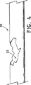
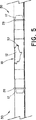
脈管の外傷を治療するのに、ステント・グラフト装置10を術中に使用する1つの例について述べる。図4は、既に外傷性の症状を発現している血管30を示している。この場合、血管30の部分32が引き裂かれているか、又は激しく損傷していることが観察できる。図5に示す様に、身体が切開された後、ステント・グラフト装置10は、ステント・グラフト本体12が少なくとも損傷した血管部分32の長さを亘るように、医師によって手で血管30内に配置される。
One example of using the stent-
図示の実施形態では、ステント・グラフト装置10は、1つ又は複数の縫合糸20をコネクタ14の露出している部分で血管の回りに結ぶことによって、血管30内で移動するのを抑制するように固定されている。最も良いのは、縫合糸20が、露出している窪み部分16で、コネクタ14の回りに結ばれることである。この様にすると、縫合糸20は、血管30の一部分を圧縮するので、血管は、図5に示す様に、各軸方向端部で窪み16の中に押し付けられ、堅固な接続を確立する。説明したやり方で本発明のステント・グラフト装置を切開手術で留置するのは、一般的に、最小限の時間で、多くは約2分程度の時間で行われる。これに対し、従来型の修復技法では、45分も、場合によってはそれ以上かかることもある。
In the illustrated embodiment, the stent-
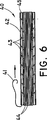
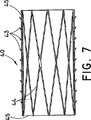
本発明による、切開手術で又は術中に留置するのに使用するためのステント・グラフト装置は、必ずしも図1に示している様に構成されていなくてもよい。その様な留置に適した他の構造であってもよく、それも本発明の範囲内にあると考えられる。その様な留置に適しているステント・グラフト装置40の1つの代替実施形態を図6に示している。この実施形態では、ステント・グラフト装置40は、図6に示している折畳まれた又は「非拡張」状態から、図7に示している拡張状態へ選択的に拡張可能である。
According to the invention, a stent-graft device for use in placement in open surgery or intraoperative may not be composed necessarily as that shown in FIG. Other structures suitable for such placement may be used and are considered to be within the scope of the present invention. One alternative embodiment of a stent-
ステント・グラフト装置40は、細長い略円筒形のステント本体44を備えている。本体44は、例えば、従来型のステント交差ワイヤーパターンの1つ又は複数のワイヤーで形成されている。布グラフト45は、ステント本体44を周知の様式で覆うように設けられている。ステント本体44を形成しているワイヤーは、その様な目的に一般的に利用されている、金属又は金属合金の様な従来型のワイヤーである。限定するわけではないが、適した組成物の例には、ステンレス鋼、並びにニチノールの様な形状記憶材料、及び磁気共鳴画像(MRI)の様な一般的な医療画像化技法の下で見ることのできる組成物が含まれる。限定するわけではないが、画像化技法の下で見ることのできる好適な組成物の1つの例は、チタンである。布グラフト45は、医療技術で周知のどの様なグラフト材料でもよく、限定するわけではないが、ステント・グラフト装置10に関連して先に述べた材料も含まれる。グラフト材料は、図面に示している様に、拡張できなければならない。EPTFEは、特に好適なグラフト材料である。当業者には理解頂けるように、他の既知の型式のステント及びグラフト材料も、ここに図示し説明している材料に置き換えることができる。
The stent-
図6は、拡張されていないステント・グラフト装置40が、従来型の送出シース42内に配置されている様子を示している。シース42は、管状構造であり、脈管内に適切に配置した後、シースからステント・グラフト装置を取り外し易くするための従来型の機構、例えば引張タブ機構又はプッシャーを有している。図6の実施形態では、取り外し機構は、引張タブ型の機構、即ちストリング41を備えている。ストリング41を矢印の方向に引っ張ると、シース42は、長手方向に裂け、その後、ステントグラフトから剥ぎ取られる。割裂に適した機構の1つの例は、インディアナ州ブルーミントンのCook社から販売されているPEELAWAY(登録商標)シースと関連して用いられる引張タブ機構である。代わりに、装置を送出シースから取り外し、及び/又は取り外すためにシースを裂くための他の従来型の機構を利用してもよい。ここに図示し、説明している型式のシースは周知技術であり、当業者には理解頂けるように、多くの既知のシースを、ここで図示し説明しているシースに置き換えることができ、そのそれぞれが本発明の範囲内にあると考えられる。
FIG. 6 illustrates the unexpanded stent-
述べた様に、ステント・グラフト装置40は、圧縮状態から拡張状態へと拡張可能である。従って、シースを裂く又は他の適切な送達機構によって、ステント・グラフトを送達した後、ステント・グラフト装置40は、図6の収縮状態から図7の拡張状態に拡張する。ステント・グラフト装置40には、該装置の外周の少なくとも一部に沿って、拡張したステント・グラフト装置を脈管内に固定させる棘43の様な固定構造が設けられているのが望ましい。当業者には理解頂けるように、フック、「魚の鱗」などの多くの適切な固定構造が周知技術では知られており、その何れも、図6及び図7に示している棘の代わりに、又は棘に加えて利用することができる。図6と図7の実施形態は、ステント・グラフトの全長に沿って棘を含んでいるが、必ずしもこの通りではなく、代わりに、棘を、ステント・グラフト装置の長さに沿った1つ又は複数の別々の場所に配置してもよい。同様に、図示の各棘は、同じ方向に向いた鋭い先端を有しているが、これは、代表的な例に過ぎず、棘の先端は、同じ方向に向いていても、反対の方向に向いていてもよい。当業者であれば、特定の使用に適した棘の先端の適切な配列を容易に選択できるであろう。
As stated, the stent-
図8と図9は、ステント・グラフト装置40を、図4に示す外傷の様な脈管外傷の部位に術中に留置する様子を示している。図8に示す様に、ステント・グラフト装置40を中に折畳まれた状態で装填しているシース42は、脈管30の脈管外傷32の部位内に、術中に留置される。シース42は、ストリング41を矢印の方向に引っ張ることによって裂かれ、シース42の両側は、従来の方式で、ステント・グラフト装置から剥がされ、又は取り除かれる。ステント・グラフト装置40は、シース42の拘束から開放されると、その後、図9に示す様に脈管内で拡張する。ステント・グラフト装置40は、拡張時外径が、脈管30の内径と少なくとも同じであるのが望ましく、また、それより幾らか大きいのが望ましい。
FIGS. 8 and 9 show a state in which the stent /
図10は、図6−9に示した配置の修正例を示している。この場合、送出シース52には、図6に示す1つのストリングではなく、2つの引張ストリングが設けられている。この変更例では、各ストリング51は、シース52の別々の軸方向端部に配置されている。ストリングがそれぞれの矢印の方向に引っ張られると、シースが裂かれる。シースが引き取られると、ステント・グラフト装置40は、開放され、脈管30内で拡張する。
FIG. 10 shows a modification example of the arrangement shown in FIGS. 6-9. In this case, the
本発明の別の実施形態を、図11と図12に示している。この実施形態では、ステント・グラフト装置60は、図6と図7に示している様な単一のワイヤーステント本体44ではなく、複数の軸方向に整列したステント64の配置を備えている。図示の実施形態では、2つのステント64が、拡張可能なステント・グラフト装置60の互いに反対側の端部に配置されている。1つ又は複数の引張ストリング61を有するシース62が、前述同様に設けられている。ステントグラフト本体65は、先に述べた何れかの構成物で形成されており、必要であれば、複数の棘63又は同様の固定構造を含んでいてもよい。
Another embodiment of the present invention is shown in FIGS. In this embodiment, the stent-
図11と図12に示している配置には、装置60の軸方向両端部に2つのステント64が配置されているが、多くの代替配置も本発明の範囲内にある。1つの可能な代替案として、装置は、ステント・グラフト装置の長さの全部又は一部に沿って配置されている一連のステントを含んでいてもよい。その様なステントは、互いに接続されていても、互いに直接隣接して配置されていても、互いに別々の距離で離間されていてもよい。ステント・グラフト装置の布は、装置の全てのステント部分を覆う又は亘っている必要はないが、少なくとも脈管の損傷部位を亘ることができるほどには設けられていなければならない。従って、この実施形態では、装置の長さに沿って配置されている複数のステントを有するステント・グラフト装置が提供されている。必要であれば、ステント・グラフト装置を、通常使用に必要とされるステントより長く及び・又は数が多くなるような寸法とすることもできる。医師は、次に、ステント・グラフト装置を所望の長さに切り取ることができる。この様にすれば、医療施設は、長さの異なる多数のステント・グラフト装置を保持しておく必要が無く、1つ又は複数の細長い装置を保管しておき、医師が、使用直前に所望の長さに切り取るようにすることができる。
While the arrangements shown in FIGS. 11 and 12 have two
図11と図12に示している実施形態の様な複数の拡張可能なステントを含む実施形態では、割裂可能な外側シースが、装置の全長に伸張している必要はない。むしろ、別々の割裂可能なシースを、ステント・グラフトの各ステント部分を覆うように設けて、ステント以外の部分を覆わないままにしてもよい。この様にすれば、各シースを、例えば、ストリング又は従来型の機構で裂くことができるので、ステント及びそれに付随してグラフト材料が損傷した脈管内で制御された拡張が可能となる。 In embodiments including multiple expandable stents, such as the embodiment shown in FIGS. 11 and 12, the splittable outer sheath need not extend the entire length of the device. Rather, separate splittable sheaths may be provided to cover each stent portion of the stent-graft, leaving the rest of the stent uncovered. In this way, each sheath can be cleaved, for example, with a string or conventional mechanism, allowing controlled expansion within the vessel where the stent and associated graft material is damaged.
本発明によれば、ステント・グラフト装置は、脈管外傷を治療する際に使用するのに備えて事実上どの様な寸法の長さを有することもできる。ステント・グラフト装置は、約1から10cmの長さを有しているのが望ましく、約3から8cmであれば更に望ましく、約6又は7cmであれば更に望ましい。ステント・グラフトは、修復を受ける損傷した脈管部分の長さより僅かに長いのが望ましい。便宜上、ステント・グラフトは、ステントグラフトの軸方向端部の少なくとも何れか一方又は両方の部分が、医師によって所望の長さに切り取られるように構成することができる。 In accordance with the present invention, the stent-graft device can have a length of virtually any dimension for use in treating vascular trauma. The stent-graft device desirably has a length of about 1 to 10 cm, more preferably about 3 to 8 cm, and more preferably about 6 or 7 cm. Desirably, the stent-graft is slightly longer than the length of the damaged vessel part undergoing repair. For convenience, the stent-graft may be configured such that at least one or both portions of the axial end of the stent-graft are trimmed to a desired length by the physician.
ここに述べているステント・グラフト装置には、更に、1つ又は複数の治療剤の被覆を備えていてもよい。生体適合性被覆として使用される治療剤は、周知技術である。限定するわけではないが、ステント・グラフト装置に使用される適した生物活性剤の例には、抗凝固剤、抗生物質製剤、抗癌剤、抗ウイルス剤、抗血管形成剤、血管形成剤、抗分裂剤、抗炎症剤、血管形成阻害剤、血管新生阻害剤、細胞周期調節剤と、エストロゲンの様なホルモン、それらの同族体、誘導体、断片を含む遺伝子剤、薬物塩、及びこれらの組み合わせとが含まれる。当業者には理解頂けるように、他の生物活性剤も特定の用途に利用することができる。生物活性剤を、意図する目的のために薬剤材料及びその効果を適切に保持することができる何れかの適した方法によって、ステント・グラフト装置の部分に組み込み、又は塗布してもよい。 The stent-graft device described herein may further be provided with a coating of one or more therapeutic agents. Therapeutic agents used as biocompatible coatings are well known in the art. Non-limiting examples of suitable bioactive agents used in stent-graft devices include anticoagulants, antibiotic formulations, anticancer agents, antiviral agents, antiangiogenic agents, angiogenic agents, antimitotics Agents, anti-inflammatory agents, angiogenesis inhibitors, angiogenesis inhibitors, cell cycle regulators, hormones such as estrogens, homologues, derivatives, fragments thereof, gene agents, drug salts, and combinations thereof included. As will be appreciated by those skilled in the art, other bioactive agents may be utilized for specific applications. The bioactive agent may be incorporated or applied to the portion of the stent-graft device by any suitable method that can adequately retain the drug material and its effect for the intended purpose.
以上、本装置について、脈管外傷を修復するという主要な使用目的に結び付けて説明してきたが、当業者には理解頂けるように、本装置は、他の外傷状態を修復するのにも用いられる。限定するわけではないが、その様な状態の例には、腹部大動脈瘤の様な動脈瘤が含まれる。 While the device has been described in connection with its primary purpose of repairing vascular trauma, as will be appreciated by those skilled in the art, the device can also be used to repair other trauma conditions. . An example of such a condition includes, but is not limited to, an aneurysm such as an abdominal aortic aneurysm.
従って、以上の詳細な説明は、限定を課すものではなく例示するものであり、本発明の意図と範囲を定義するのは、全ての等価物を含め特許請求の範囲であると理解されたい。 Accordingly, the foregoing detailed description is intended to be illustrative rather than limiting, and it is to be understood that it is the claims, including all equivalents, that define the spirit and scope of the present invention.
Claims (6)
Applications Claiming Priority (3)
| Application Number | Priority Date | Filing Date | Title |
|---|---|---|---|
| US70292405P | 2005-07-27 | 2005-07-27 | |
| US60/702,924 | 2005-07-27 | ||
| PCT/US2006/029046 WO2007016166A2 (en) | 2005-07-27 | 2006-07-26 | Stent/graft device and method for open surgical placement |
Publications (3)
| Publication Number | Publication Date |
|---|---|
| JP2009502343A JP2009502343A (en) | 2009-01-29 |
| JP2009502343A5 JP2009502343A5 (en) | 2009-09-10 |
| JP5203192B2 true JP5203192B2 (en) | 2013-06-05 |
Family
ID=37307603
Family Applications (1)
| Application Number | Title | Priority Date | Filing Date |
|---|---|---|---|
| JP2008524111A Active JP5203192B2 (en) | 2005-07-27 | 2006-07-26 | Stent / graft device and method for placement in open surgery |
Country Status (6)
| Country | Link |
|---|---|
| US (2) | US8202311B2 (en) |
| EP (1) | EP1906879B1 (en) |
| JP (1) | JP5203192B2 (en) |
| AU (1) | AU2006275881B2 (en) |
| CA (2) | CA2829353C (en) |
| WO (1) | WO2007016166A2 (en) |
Families Citing this family (61)
| Publication number | Priority date | Publication date | Assignee | Title |
|---|---|---|---|---|
| US6261316B1 (en) | 1999-03-11 | 2001-07-17 | Endologix, Inc. | Single puncture bifurcation graft deployment system |
| US8034100B2 (en) * | 1999-03-11 | 2011-10-11 | Endologix, Inc. | Graft deployment system |
| US8038708B2 (en) * | 2001-02-05 | 2011-10-18 | Cook Medical Technologies Llc | Implantable device with remodelable material and covering material |
| US20070027535A1 (en) * | 2005-07-28 | 2007-02-01 | Cook Incorporated | Implantable thromboresistant valve |
| US20050216043A1 (en) * | 2004-03-26 | 2005-09-29 | Blatter Duane D | Stented end graft vessel device for anastomosis and related methods for percutaneous placement |
| US9375215B2 (en) | 2006-01-20 | 2016-06-28 | W. L. Gore & Associates, Inc. | Device for rapid repair of body conduits |
| DE102007022060A1 (en) | 2007-05-11 | 2008-11-13 | Rubenstein, Nicola M., Dr. | Device for connecting two blood vessels |
| US20130197546A1 (en) | 2007-08-02 | 2013-08-01 | Bioconnect Systems, Inc. | Implantable flow connector |
| WO2009018583A1 (en) | 2007-08-02 | 2009-02-05 | Bio Connect Systems | Implantable flow connector |
| US8906081B2 (en) | 2007-09-13 | 2014-12-09 | W. L. Gore & Associates, Inc. | Stented vascular graft |
| JP2011500283A (en) | 2007-10-26 | 2011-01-06 | クック クリティカル ケア インコーポレーテッド | Vascular conduit and delivery system installed in open surgery |
| US8221494B2 (en) | 2008-02-22 | 2012-07-17 | Endologix, Inc. | Apparatus and method of placement of a graft or graft system |
| US8236040B2 (en) | 2008-04-11 | 2012-08-07 | Endologix, Inc. | Bifurcated graft deployment systems and methods |
| JP5134729B2 (en) | 2008-07-01 | 2013-01-30 | エンドロジックス、インク | Catheter system |
| US20110054586A1 (en) | 2009-04-28 | 2011-03-03 | Endologix, Inc. | Apparatus and method of placement of a graft or graft system |
| CA3009244C (en) | 2009-06-23 | 2020-04-28 | Endospan Ltd. | Vascular prostheses for treating aneurysms |
| US9192463B2 (en) | 2010-08-03 | 2015-11-24 | Cook Medical Technologies, LLC | Blood perfusion device |
| US10271970B2 (en) | 2010-08-03 | 2019-04-30 | Cook Medical Technologies Llc | Blood perfusion device |
| US20120109279A1 (en) | 2010-11-02 | 2012-05-03 | Endologix, Inc. | Apparatus and method of placement of a graft or graft system |
| US9675487B2 (en) * | 2010-11-17 | 2017-06-13 | Cook Medical Technologies Llc | Prosthesis deployment system for vascular repair |
| US9526638B2 (en) | 2011-02-03 | 2016-12-27 | Endospan Ltd. | Implantable medical devices constructed of shape memory material |
| US8808350B2 (en) | 2011-03-01 | 2014-08-19 | Endologix, Inc. | Catheter system and methods of using same |
| US8784474B2 (en) | 2011-04-21 | 2014-07-22 | Cook Medical Technologies Llc | Emergency vascular repair system and method |
| US20120290072A1 (en) | 2011-05-12 | 2012-11-15 | Theobald Elizabeth A | Emergency vascular repair prosthesis |
| US20130041451A1 (en) * | 2011-08-09 | 2013-02-14 | Cook Medical Technologies Llc | Prosthesis deployment system for open surgical repair |
| WO2013028605A1 (en) | 2011-08-22 | 2013-02-28 | Cook Medical Technologies Llc | Emergency vessel repair prosthesis deployment system |
| WO2013065040A1 (en) | 2011-10-30 | 2013-05-10 | Endospan Ltd. | Triple-collar stent-graft |
| EP2785277B1 (en) | 2011-12-04 | 2017-04-05 | Endospan Ltd. | Branched stent-graft system |
| US10342548B2 (en) * | 2012-01-13 | 2019-07-09 | W. L. Gore & Associates, Inc. | Occlusion devices and methods of their manufacture and use |
| US10434293B2 (en) | 2012-04-15 | 2019-10-08 | Tva Medical, Inc. | Implantable flow connector |
| JP2015515329A (en) * | 2012-04-15 | 2015-05-28 | バイオコネクト システムズ インコーポレイテッド | Portable flow connector |
| US9314600B2 (en) | 2012-04-15 | 2016-04-19 | Bioconnect Systems, Inc. | Delivery system for implantable flow connector |
| US11458007B2 (en) * | 2012-08-10 | 2022-10-04 | W. L. Gore & Associates, Inc. | Devices and methods for limiting a depth of penetration for an anchor within an anatomy |
| US10226270B2 (en) * | 2012-08-10 | 2019-03-12 | W. L. Gore & Associates, Inc. | Microanchors for anchoring devices to body tissues |
| US11547396B2 (en) * | 2012-08-10 | 2023-01-10 | W. L. Gore & Associates, Inc. | Devices and methods for securing medical devices within an anatomy |
| US9345566B2 (en) | 2012-09-26 | 2016-05-24 | Cook Medical Technologies Llc | Delivery device and system for open surgical repair |
| US9808333B2 (en) | 2012-09-26 | 2017-11-07 | Cook Medical Technologies Llc | Splittable sheath |
| WO2014108895A2 (en) | 2013-01-08 | 2014-07-17 | Endospan Ltd. | Minimization of stent-graft migration during implantation |
| EP2948049B1 (en) | 2013-01-24 | 2024-04-24 | Alio, Inc. | Prosthesis for measuring fluid flow through a lumen |
| WO2014141232A1 (en) | 2013-03-11 | 2014-09-18 | Endospan Ltd. | Multi-component stent-graft system for aortic dissections |
| EP2968688B1 (en) * | 2013-03-15 | 2018-08-08 | Boston Scientific Scimed, Inc. | Anti-migratory stent coating |
| US10603197B2 (en) | 2013-11-19 | 2020-03-31 | Endospan Ltd. | Stent system with radial-expansion locking |
| US9855155B2 (en) * | 2014-06-26 | 2018-01-02 | Cardinal Health Switzeerland 515 Gmbh | Endoprosthesis anchoring and sealing |
| CN104188741A (en) * | 2014-08-29 | 2014-12-10 | 东莞颠覆产品设计有限公司 | Degradable connector implanted in body |
| WO2016073199A1 (en) | 2014-11-05 | 2016-05-12 | Cook Medical Technologies Llc | Dissolvable sleeve configurations to aid graft deployment |
| WO2016098113A1 (en) | 2014-12-18 | 2016-06-23 | Endospan Ltd. | Endovascular stent-graft with fatigue-resistant lateral tube |
| KR102021685B1 (en) * | 2015-02-20 | 2019-09-16 | 보스톤 싸이엔티픽 싸이메드 인코포레이티드 | Stent with retractable anchor |
| US9924905B2 (en) | 2015-03-09 | 2018-03-27 | Graftworx, Inc. | Sensor position on a prosthesis for detection of a stenosis |
| CN107624056B (en) | 2015-06-30 | 2020-06-09 | 恩朵罗杰克斯股份有限公司 | Locking assembly and related system and method |
| US10596330B2 (en) | 2015-08-26 | 2020-03-24 | Medtronic Xomed, Inc. | Resorbable, drug-eluting submucosal turbinate implant device and method |
| CA3001249C (en) | 2015-10-12 | 2023-10-17 | Reflow Medical, Inc. | Stents having protruding drug-delivery features and associated systems and methods |
| GB2550938B (en) | 2016-06-01 | 2018-07-11 | Cook Medical Technologies Llc | Medical device introducer assembly particularly for branched medical devices |
| WO2018049412A1 (en) | 2016-09-12 | 2018-03-15 | Graftworx, Inc. | Wearable device with multimodal diagnostics |
| CN106422049B (en) * | 2016-10-31 | 2022-07-19 | 黄剑 | Bridging bracket based on blood circulation temporary recovery and processing method thereof |
| US10603193B2 (en) | 2016-11-09 | 2020-03-31 | Boston Scientific Scimed, Inc. | Stent anchoring system |
| EP4238539A3 (en) * | 2017-10-25 | 2023-10-18 | Boston Scientific Scimed, Inc. | Stent with atraumatic spacer |
| CN108078658A (en) * | 2017-12-12 | 2018-05-29 | 内蒙古工业大学 | A kind of arch aorta tectorial membrane stent |
| WO2019232263A1 (en) * | 2018-05-31 | 2019-12-05 | Endologix, Inc. | Systems and methods with anchor device for fixation of filling structures in blood vessels |
| CN111096823B (en) * | 2018-10-25 | 2022-01-18 | 深圳市先健畅通医疗有限公司 | Covered stent |
| US11925570B2 (en) | 2018-12-19 | 2024-03-12 | Boston Scientific Scimed, Inc. | Stent including anti-migration capabilities |
| JP2023551927A (en) | 2020-12-02 | 2023-12-13 | ボストン サイエンティフィック サイムド,インコーポレイテッド | Stents with improved deployment characteristics |
Family Cites Families (107)
| Publication number | Priority date | Publication date | Assignee | Title |
|---|---|---|---|---|
| US3657744A (en) | 1970-05-08 | 1972-04-25 | Univ Minnesota | Method for fixing prosthetic implants in a living body |
| JPS6028434Y2 (en) | 1980-06-16 | 1985-08-28 | 建部 容保 | Artificial blood vessel |
| US6221102B1 (en) * | 1983-12-09 | 2001-04-24 | Endovascular Technologies, Inc. | Intraluminal grafting system |
| US5275622A (en) | 1983-12-09 | 1994-01-04 | Harrison Medical Technologies, Inc. | Endovascular grafting apparatus, system and method and devices for use therewith |
| US5693083A (en) | 1983-12-09 | 1997-12-02 | Endovascular Technologies, Inc. | Thoracic graft and delivery catheter |
| US4787899A (en) | 1983-12-09 | 1988-11-29 | Lazarus Harrison M | Intraluminal graft device, system and method |
| US5669936A (en) | 1983-12-09 | 1997-09-23 | Endovascular Technologies, Inc. | Endovascular grafting system and method for use therewith |
| US5104399A (en) * | 1986-12-10 | 1992-04-14 | Endovascular Technologies, Inc. | Artificial graft and implantation method |
| US4580568A (en) | 1984-10-01 | 1986-04-08 | Cook, Incorporated | Percutaneous endovascular stent and method for insertion thereof |
| US4728328A (en) * | 1984-10-19 | 1988-03-01 | Research Corporation | Cuffed tubular organic prostheses |
| US5078726A (en) | 1989-02-01 | 1992-01-07 | Kreamer Jeffry W | Graft stent and method of repairing blood vessels |
| US5152782A (en) | 1989-05-26 | 1992-10-06 | Impra, Inc. | Non-porous coated ptfe graft |
| US5578071A (en) | 1990-06-11 | 1996-11-26 | Parodi; Juan C. | Aortic graft |
| US5360443A (en) | 1990-06-11 | 1994-11-01 | Barone Hector D | Aortic graft for repairing an abdominal aortic aneurysm |
| AU633453B2 (en) | 1990-10-09 | 1993-01-28 | Cook Incorporated | Percutaneous stent assembly |
| CA2202800A1 (en) | 1991-04-11 | 1992-10-12 | Alec A. Piplani | Endovascular graft having bifurcation and apparatus and method for deploying the same |
| US5628783A (en) | 1991-04-11 | 1997-05-13 | Endovascular Technologies, Inc. | Bifurcated multicapsule intraluminal grafting system and method |
| US5304220A (en) | 1991-07-03 | 1994-04-19 | Maginot Thomas J | Method and apparatus for implanting a graft prosthesis in the body of a patient |
| US5720776A (en) | 1991-10-25 | 1998-02-24 | Cook Incorporated | Barb and expandable transluminal graft prosthesis for repair of aneurysm |
| US5316023A (en) | 1992-01-08 | 1994-05-31 | Expandable Grafts Partnership | Method for bilateral intra-aortic bypass |
| US5330490A (en) * | 1992-04-10 | 1994-07-19 | Wilk Peter J | Endoscopic device, prosthesis and method for use in endovascular repair |
| JPH06319755A (en) | 1993-05-10 | 1994-11-22 | Sumitomo Electric Ind Ltd | Connector for artificial blood vessel and manufacture thereof |
| US5425765A (en) | 1993-06-25 | 1995-06-20 | Tiefenbrun; Jonathan | Surgical bypass method |
| US5735892A (en) | 1993-08-18 | 1998-04-07 | W. L. Gore & Associates, Inc. | Intraluminal stent graft |
| DE69433617T2 (en) * | 1993-09-30 | 2005-03-03 | Endogad Research Pty Ltd. | INTRALUMINAL TRANSPLANT |
| US5476506A (en) | 1994-02-08 | 1995-12-19 | Ethicon, Inc. | Bi-directional crimped graft |
| US6051020A (en) | 1994-02-09 | 2000-04-18 | Boston Scientific Technology, Inc. | Bifurcated endoluminal prosthesis |
| US5683451A (en) * | 1994-06-08 | 1997-11-04 | Cardiovascular Concepts, Inc. | Apparatus and methods for deployment release of intraluminal prostheses |
| US5824041A (en) | 1994-06-08 | 1998-10-20 | Medtronic, Inc. | Apparatus and methods for placement and repositioning of intraluminal prostheses |
| DE69530891T2 (en) * | 1994-06-27 | 2004-05-13 | Corvita Corp., Miami | Bistable luminal graft endoprostheses |
| US5522881A (en) | 1994-06-28 | 1996-06-04 | Meadox Medicals, Inc. | Implantable tubular prosthesis having integral cuffs |
| US5575817A (en) | 1994-08-19 | 1996-11-19 | Martin; Eric C. | Aorto femoral bifurcation graft and method of implantation |
| US6331188B1 (en) | 1994-08-31 | 2001-12-18 | Gore Enterprise Holdings, Inc. | Exterior supported self-expanding stent-graft |
| US5527355A (en) | 1994-09-02 | 1996-06-18 | Ahn; Sam S. | Apparatus and method for performing aneurysm repair |
| US6015429A (en) | 1994-09-08 | 2000-01-18 | Gore Enterprise Holdings, Inc. | Procedures for introducing stents and stent-grafts |
| NL9500095A (en) * | 1995-01-19 | 1996-09-02 | Industrial Res Bv | Expandable carrier balloon for a stent assembly. |
| US5755770A (en) | 1995-01-31 | 1998-05-26 | Boston Scientific Corporatiion | Endovascular aortic graft |
| US5522883A (en) | 1995-02-17 | 1996-06-04 | Meadox Medicals, Inc. | Endoprosthesis stent/graft deployment system |
| US6451047B2 (en) * | 1995-03-10 | 2002-09-17 | Impra, Inc. | Encapsulated intraluminal stent-graft and methods of making same |
| US5647857A (en) * | 1995-03-16 | 1997-07-15 | Endotex Interventional Systems, Inc. | Protective intraluminal sheath |
| US6863686B2 (en) | 1995-04-17 | 2005-03-08 | Donald Shannon | Radially expandable tape-reinforced vascular grafts |
| US5641373A (en) | 1995-04-17 | 1997-06-24 | Baxter International Inc. | Method of manufacturing a radially-enlargeable PTFE tape-reinforced vascular graft |
| DE69635659T2 (en) * | 1995-06-01 | 2006-07-06 | Meadox Medicals, Inc. | IMPLANTABLE INTRALUMINARY PROSTHESIS |
| US6814748B1 (en) | 1995-06-07 | 2004-11-09 | Endovascular Technologies, Inc. | Intraluminal grafting system |
| US5785679A (en) | 1995-07-19 | 1998-07-28 | Endotex Interventional Systems, Inc. | Methods and apparatus for treating aneurysms and arterio-venous fistulas |
| US5769882A (en) | 1995-09-08 | 1998-06-23 | Medtronic, Inc. | Methods and apparatus for conformably sealing prostheses within body lumens |
| EP0851746A1 (en) | 1995-09-18 | 1998-07-08 | W.L. Gore & Associates, Inc. | A delivery system for intraluminal vascular grafts |
| US5591195A (en) | 1995-10-30 | 1997-01-07 | Taheri; Syde | Apparatus and method for engrafting a blood vessel |
| US5824040A (en) | 1995-12-01 | 1998-10-20 | Medtronic, Inc. | Endoluminal prostheses and therapies for highly variable body lumens |
| WO1997021402A1 (en) | 1995-12-14 | 1997-06-19 | Prograft Medical, Inc. | Stent-graft deployment apparatus and method |
| US5928279A (en) * | 1996-07-03 | 1999-07-27 | Baxter International Inc. | Stented, radially expandable, tubular PTFE grafts |
| WO1998019625A2 (en) | 1996-11-08 | 1998-05-14 | Houser Russell A | Percutaneous bypass graft and securing system |
| US6352561B1 (en) | 1996-12-23 | 2002-03-05 | W. L. Gore & Associates | Implant deployment apparatus |
| US5961545A (en) | 1997-01-17 | 1999-10-05 | Meadox Medicals, Inc. | EPTFE graft-stent composite device |
| US6048360A (en) * | 1997-03-18 | 2000-04-11 | Endotex Interventional Systems, Inc. | Methods of making and using coiled sheet graft for single and bifurcated lumens |
| US6306164B1 (en) | 1997-09-05 | 2001-10-23 | C. R. Bard, Inc. | Short body endoprosthesis |
| FR2768921B1 (en) * | 1997-10-01 | 1999-12-10 | Braun Celsa Sa | ASSEMBLY COMPRISING AN INTRALUMINAL PROSTHESIS AND A MEANS FOR SEALING SUCH A PROSTHESIS |
| WO1999025280A1 (en) | 1997-11-14 | 1999-05-27 | Boston Scientific Limited | Multi-sheath delivery catheter |
| US6077296A (en) | 1998-03-04 | 2000-06-20 | Endologix, Inc. | Endoluminal vascular prosthesis |
| US6656215B1 (en) | 2000-11-16 | 2003-12-02 | Cordis Corporation | Stent graft having an improved means for attaching a stent to a graft |
| US6224627B1 (en) * | 1998-06-15 | 2001-05-01 | Gore Enterprise Holdings, Inc. | Remotely removable covering and support |
| US6168619B1 (en) * | 1998-10-16 | 2001-01-02 | Quanam Medical Corporation | Intravascular stent having a coaxial polymer member and end sleeves |
| US6214036B1 (en) | 1998-11-09 | 2001-04-10 | Cordis Corporation | Stent which is easily recaptured and repositioned within the body |
| US20020065546A1 (en) | 1998-12-31 | 2002-05-30 | Machan Lindsay S. | Stent grafts with bioactive coatings |
| US20050171594A1 (en) | 1998-12-31 | 2005-08-04 | Angiotech International Ag | Stent grafts with bioactive coatings |
| WO2000042949A2 (en) | 1999-01-22 | 2000-07-27 | Gore Enterprise Holdings, Inc. | A biliary stent-graft |
| US6398803B1 (en) * | 1999-02-02 | 2002-06-04 | Impra, Inc., A Subsidiary Of C.R. Bard, Inc. | Partial encapsulation of stents |
| US6162246A (en) | 1999-02-16 | 2000-12-19 | Barone; Hector Daniel | Aortic graft and method of treating abdominal aortic aneurysms |
| US6261316B1 (en) | 1999-03-11 | 2001-07-17 | Endologix, Inc. | Single puncture bifurcation graft deployment system |
| US7226467B2 (en) | 1999-04-09 | 2007-06-05 | Evalve, Inc. | Fixation device delivery catheter, systems and methods of use |
| US6287335B1 (en) | 1999-04-26 | 2001-09-11 | William J. Drasler | Intravascular folded tubular endoprosthesis |
| US6780497B1 (en) | 1999-08-05 | 2004-08-24 | Gore Enterprise Holdings, Inc. | Surface modified expanded polytetrafluoroethylene devices and methods of producing the same |
| US6849087B1 (en) | 1999-10-06 | 2005-02-01 | Timothy A. M. Chuter | Device and method for staged implantation of a graft for vascular repair |
| US6663667B2 (en) | 1999-12-29 | 2003-12-16 | Edwards Lifesciences Corporation | Towel graft means for enhancing tissue ingrowth in vascular grafts |
| US6409756B1 (en) | 2000-01-24 | 2002-06-25 | Edward G. Murphy | Endovascular aortic graft |
| US6319278B1 (en) | 2000-03-03 | 2001-11-20 | Stephen F. Quinn | Low profile device for the treatment of vascular abnormalities |
| EP1311210B1 (en) * | 2000-08-23 | 2006-10-11 | LeMaitre Acquisition LLC | Method of manufacturing custom intravascular devices |
| DE10104806A1 (en) * | 2001-01-26 | 2002-08-14 | Univ Eberhard Karls | Vessel prosthesis for humans or animals uses connector at main body sleeve end as flat and expanded sleeve joined by transition surface and pressed to vessel at connector by flexible encircling band. |
| US20020107535A1 (en) * | 2001-02-08 | 2002-08-08 | Jeng Wei | Union for connection of artificial vessel to human vessel |
| US6767359B2 (en) | 2001-09-28 | 2004-07-27 | Ethicon, Inc. | Prosthesis for the repair of thoracic or abdominal aortic aneurysms and method therefor |
| US20030074055A1 (en) | 2001-10-17 | 2003-04-17 | Haverkost Patrick A. | Method and system for fixation of endoluminal devices |
| US6929661B2 (en) | 2001-11-28 | 2005-08-16 | Aptus Endosystems, Inc. | Multi-lumen prosthesis systems and methods |
| AU2002353807B2 (en) | 2001-11-28 | 2008-08-14 | Aptus Endosystems, Inc. | Endovascular aneurysm repair system |
| US7128754B2 (en) | 2001-11-28 | 2006-10-31 | Aptus Endosystems, Inc. | Catheter-based fastener implantation apparatus and methods |
| US20050070992A1 (en) | 2001-11-28 | 2005-03-31 | Aptus Endosystems, Inc. | Prosthesis systems and methods sized and configured for the receipt and retention of fasteners |
| US7147661B2 (en) | 2001-12-20 | 2006-12-12 | Boston Scientific Santa Rosa Corp. | Radially expandable stent |
| US7331992B2 (en) | 2002-02-20 | 2008-02-19 | Bard Peripheral Vascular, Inc. | Anchoring device for an endoluminal prosthesis |
| US7288111B1 (en) * | 2002-03-26 | 2007-10-30 | Thoratec Corporation | Flexible stent and method of making the same |
| CA2489495C (en) | 2002-06-28 | 2010-07-13 | Cook Incorporated | Thoracic aortic aneurysm stent graft |
| US7550004B2 (en) | 2002-08-20 | 2009-06-23 | Cook Biotech Incorporated | Endoluminal device with extracellular matrix material and methods |
| US20040098096A1 (en) | 2002-10-22 | 2004-05-20 | The University Of Miami | Endograft device to inhibit endoleak and migration |
| WO2004060424A2 (en) | 2002-12-30 | 2004-07-22 | Angiotech International Ag | Silk-containing stent graft |
| US6852122B2 (en) | 2003-01-23 | 2005-02-08 | Cordis Corporation | Coated endovascular AAA device |
| US20050049672A1 (en) * | 2003-03-24 | 2005-03-03 | Murphy Kieran P. | Stent delivery system and method using a balloon for a self-expandable stent |
| EP1613242B1 (en) | 2003-03-26 | 2013-02-20 | The Foundry, LLC | Devices for treatment of abdominal aortic aneurysms |
| US20040215338A1 (en) * | 2003-04-24 | 2004-10-28 | Jeff Elkins | Method and system for drug delivery to abdominal aortic or thoracic aortic aneurysms |
| US8721710B2 (en) | 2003-08-11 | 2014-05-13 | Hdh Medical Ltd. | Anastomosis system and method |
| US8292943B2 (en) | 2003-09-03 | 2012-10-23 | Bolton Medical, Inc. | Stent graft with longitudinal support member |
| US7122052B2 (en) | 2003-09-29 | 2006-10-17 | Stout Medical Group Lp | Integral support stent graft assembly |
| US20050080482A1 (en) | 2003-10-14 | 2005-04-14 | Craig Bonsignore | Graft coupling apparatus and methods of using same |
| WO2005039445A2 (en) * | 2003-10-23 | 2005-05-06 | Peacock James C Iii | Stent-graft assembly formed insitu |
| US9254213B2 (en) | 2004-01-09 | 2016-02-09 | Rubicon Medical, Inc. | Stent delivery device |
| EP1713525B1 (en) | 2004-02-09 | 2010-06-16 | Cook Incorporated | Cast bioremodelable graft |
| US20050266042A1 (en) | 2004-05-27 | 2005-12-01 | Medtronic Vascular, Inc. | Methods and apparatus for treatment of aneurysmal tissue |
| US7727271B2 (en) | 2004-06-24 | 2010-06-01 | Boston Scientific Scimed, Inc. | Implantable prosthesis having reinforced attachment sites |
| ATE390096T1 (en) | 2004-07-28 | 2008-04-15 | Cordis Corp | INTRODUCER DEVICE WITH A LOW EXPANSION FORCE |
| US7695506B2 (en) * | 2004-09-21 | 2010-04-13 | Boston Scientific Scimed, Inc. | Atraumatic connections for multi-component stents |
-
2006
- 2006-07-26 EP EP06800360.7A patent/EP1906879B1/en active Active
- 2006-07-26 AU AU2006275881A patent/AU2006275881B2/en active Active
- 2006-07-26 WO PCT/US2006/029046 patent/WO2007016166A2/en active Application Filing
- 2006-07-26 US US11/493,076 patent/US8202311B2/en active Active
- 2006-07-26 CA CA2829353A patent/CA2829353C/en active Active
- 2006-07-26 CA CA2615535A patent/CA2615535C/en active Active
- 2006-07-26 JP JP2008524111A patent/JP5203192B2/en active Active
-
2012
- 2012-05-22 US US13/477,452 patent/US8821565B2/en active Active
Also Published As
| Publication number | Publication date |
|---|---|
| CA2615535C (en) | 2013-12-24 |
| AU2006275881B2 (en) | 2012-04-12 |
| EP1906879B1 (en) | 2013-11-06 |
| WO2007016166A2 (en) | 2007-02-08 |
| US8202311B2 (en) | 2012-06-19 |
| CA2829353A1 (en) | 2007-02-08 |
| CA2829353C (en) | 2016-03-15 |
| WO2007016166A3 (en) | 2007-06-14 |
| US20070027526A1 (en) | 2007-02-01 |
| JP2009502343A (en) | 2009-01-29 |
| US8821565B2 (en) | 2014-09-02 |
| EP1906879A2 (en) | 2008-04-09 |
| CA2615535A1 (en) | 2007-02-08 |
| US20120232637A1 (en) | 2012-09-13 |
| AU2006275881A1 (en) | 2007-02-08 |
Similar Documents
| Publication | Publication Date | Title |
|---|---|---|
| JP5203192B2 (en) | Stent / graft device and method for placement in open surgery | |
| US11278390B2 (en) | Stent graft with fenestration lock and methods of use | |
| JP5972896B2 (en) | Prosthesis placement system for vascular repair | |
| US9314358B2 (en) | Emergency vascular repair prosthesis deployment system | |
| US10299791B2 (en) | Endovascular aneurysm repair system | |
| US6767359B2 (en) | Prosthesis for the repair of thoracic or abdominal aortic aneurysms and method therefor | |
| CA2767596C (en) | Apparatus for closure of a lumen and methods of using the same | |
| AU2005232726B2 (en) | Stent graft repair device | |
| US8784474B2 (en) | Emergency vascular repair system and method | |
| US9918824B2 (en) | Blood perfusion device delivery system | |
| JPH09117511A (en) | Combining assembly of stend and blood vessel transplant piece | |
| JP2023017942A (en) | tubular medical device | |
| US20160235567A1 (en) | Delivery device and system for open surgical repair | |
| AU2012203946B2 (en) | Stent/graft device and method for open surgical placement |
Legal Events
| Date | Code | Title | Description |
|---|---|---|---|
| A521 | Request for written amendment filed |
Free format text: JAPANESE INTERMEDIATE CODE: A523 Effective date: 20090723 |
|
| A621 | Written request for application examination |
Free format text: JAPANESE INTERMEDIATE CODE: A621 Effective date: 20090723 |
|
| A977 | Report on retrieval |
Free format text: JAPANESE INTERMEDIATE CODE: A971007 Effective date: 20110526 |
|
| A131 | Notification of reasons for refusal |
Free format text: JAPANESE INTERMEDIATE CODE: A131 Effective date: 20110531 |
|
| A601 | Written request for extension of time |
Free format text: JAPANESE INTERMEDIATE CODE: A601 Effective date: 20110831 |
|
| A602 | Written permission of extension of time |
Free format text: JAPANESE INTERMEDIATE CODE: A602 Effective date: 20110907 |
|
| A601 | Written request for extension of time |
Free format text: JAPANESE INTERMEDIATE CODE: A601 Effective date: 20110930 |
|
| A602 | Written permission of extension of time |
Free format text: JAPANESE INTERMEDIATE CODE: A602 Effective date: 20111007 |
|
| A601 | Written request for extension of time |
Free format text: JAPANESE INTERMEDIATE CODE: A601 Effective date: 20111028 |
|
| A602 | Written permission of extension of time |
Free format text: JAPANESE INTERMEDIATE CODE: A602 Effective date: 20111107 |
|
| A521 | Request for written amendment filed |
Free format text: JAPANESE INTERMEDIATE CODE: A523 Effective date: 20111130 |
|
| A131 | Notification of reasons for refusal |
Free format text: JAPANESE INTERMEDIATE CODE: A131 Effective date: 20120417 |
|
| A521 | Request for written amendment filed |
Free format text: JAPANESE INTERMEDIATE CODE: A523 Effective date: 20120717 |
|
| A711 | Notification of change in applicant |
Free format text: JAPANESE INTERMEDIATE CODE: A711 Effective date: 20120801 |
|
| TRDD | Decision of grant or rejection written | ||
| A01 | Written decision to grant a patent or to grant a registration (utility model) |
Free format text: JAPANESE INTERMEDIATE CODE: A01 Effective date: 20130116 |
|
| A61 | First payment of annual fees (during grant procedure) |
Free format text: JAPANESE INTERMEDIATE CODE: A61 Effective date: 20130213 |
|
| R150 | Certificate of patent or registration of utility model |
Ref document number: 5203192 Country of ref document: JP Free format text: JAPANESE INTERMEDIATE CODE: R150 Free format text: JAPANESE INTERMEDIATE CODE: R150 |
|
| FPAY | Renewal fee payment (event date is renewal date of database) |
Free format text: PAYMENT UNTIL: 20160222 Year of fee payment: 3 |
|
| R250 | Receipt of annual fees |
Free format text: JAPANESE INTERMEDIATE CODE: R250 |
|
| R250 | Receipt of annual fees |
Free format text: JAPANESE INTERMEDIATE CODE: R250 |
|
| R250 | Receipt of annual fees |
Free format text: JAPANESE INTERMEDIATE CODE: R250 |
|
| R250 | Receipt of annual fees |
Free format text: JAPANESE INTERMEDIATE CODE: R250 |
|
| R250 | Receipt of annual fees |
Free format text: JAPANESE INTERMEDIATE CODE: R250 |
|
| R250 | Receipt of annual fees |
Free format text: JAPANESE INTERMEDIATE CODE: R250 |
|
| R250 | Receipt of annual fees |
Free format text: JAPANESE INTERMEDIATE CODE: R250 |
|
| R250 | Receipt of annual fees |
Free format text: JAPANESE INTERMEDIATE CODE: R250 |
|
| R250 | Receipt of annual fees |
Free format text: JAPANESE INTERMEDIATE CODE: R250 |