JP5200529B2 - Cultivator - Google Patents
Cultivator Download PDFInfo
- Publication number
- JP5200529B2 JP5200529B2 JP2007336888A JP2007336888A JP5200529B2 JP 5200529 B2 JP5200529 B2 JP 5200529B2 JP 2007336888 A JP2007336888 A JP 2007336888A JP 2007336888 A JP2007336888 A JP 2007336888A JP 5200529 B2 JP5200529 B2 JP 5200529B2
- Authority
- JP
- Japan
- Prior art keywords
- shifter
- speed
- traveling
- stay
- tilling
- Prior art date
- Legal status (The legal status is an assumption and is not a legal conclusion. Google has not performed a legal analysis and makes no representation as to the accuracy of the status listed.)
- Expired - Fee Related
Links
- 230000005540 biological transmission Effects 0.000 claims description 87
- 238000003971 tillage Methods 0.000 claims description 49
- 210000000078 claw Anatomy 0.000 claims description 9
- 230000007935 neutral effect Effects 0.000 claims description 5
- 238000010586 diagram Methods 0.000 description 4
- 230000000694 effects Effects 0.000 description 1
- 238000000034 method Methods 0.000 description 1
Images


Landscapes
- Soil Working Implements (AREA)
- Arrangement Or Mounting Of Control Devices For Change-Speed Gearing (AREA)
Description
本発明は、耕耘機に関するものである。 The present invention relates to a cultivator.
特許文献1には、走行の変速と耕耘作業の入切が一本の変速レバーで行なえる耕耘機について記載されている。
圃場の状態によっては耕耘走行速度を変更したい場合がある。例えば固い圃場では遅い走行速度でゆっくりと圃場を耕耘作業を行なうことでよく圃場を攪拌し、軟らかい圃場の場合には速い走行速度で耕耘作業を行なうことで能率よく作業を行なえる。しかしながら、特許文献1においては、耕耘作業時の走行速度が一定のため圃場の状態に応じた耕耘作業が行い難い。
Depending on the state of the field, you may want to change the tillage speed. For example, in a hard field, the field can be stirred well by slowly cultivating the field at a slow traveling speed, and in a soft field, the work can be efficiently performed by performing the cultivating work at a high traveling speed. However, in
本発明は、異なる走行速度で耕耘作業を行なえることを課題とする。また、簡単な操作で安全な耕耘作業を行なうことを課題とする。 It is an object of the present invention to perform tillage work at different traveling speeds. Moreover, let it be a subject to perform safe tillage work by simple operation.
本発明は、上記課題を解決するために以下のような技術的手段を講じた。
すなわち、請求項1記載の発明は、走行車輪(4L,4R)と、圃場を耕耘する耕耘爪(6)と、走行車輪(4L,4R)の走行速度を低速(F1)又は中速(F2)に変速する走行変速ギヤ(22)と、耕耘爪(6)の駆動を入り切りする耕耘伝動ギヤ(31)と、前記走行変速ギヤ(22)を所定の速度位置に移動する走行変速シフタステー(50)と、耕耘伝動ギヤ(31)を駆動入位置と駆動切位置に移動する耕耘入切シフタステー(60)と、該走行変速シフタステー(50)と耕耘入切シフタステー(60)の移動を操作するシフタ操作レバー(Y)と、該シフタ操作レバー(Y)の移動を案内する案内溝(70)とを設け、走行変速シフタステー(50)及び耕耘入切シフタステー(60)にはそれぞれシフタ操作レバー(Y)が係脱可能とする操作溝部(55,61a,61b)を設け、案内溝(70)は低速(F1)又は中速(F2)に変速操作を案内する走行変速案内溝部(70a)と、耕耘作業の入切操作を案内する耕耘入切案内溝部(70b,70c)とから構成し、耕耘入切案内溝部(70b,70c)は走行変速案内溝部(70a)の低速(F1)の位置から分岐して形成する第一耕耘入切案内溝部(70b)と、走行変速案内溝部(70a)の中速(F2)の位置から分岐して形成する第二耕耘入切案内溝部(70c)とを設け、走行シフタステー(50)には、高速・中速・低速・中立・後進用の位置決め用溝部(51a〜51e)を設けると共に、シフタ操作レバー(Y)を係脱させる操作溝部(55)を設け、走行シフタステー(50)の位置決め用溝部(51a〜51e)の内、高速用の位置決め用溝部(51d)を中速用の位置決め溝部(51e)と低速用の位置決め溝部(51c)の間に形成し、耕耘入切シフタステー(60)には、シフタ操作レバー(Y)を係脱させる低速用の操作溝部(61a)と中速用の操作溝部(61b)を設け、走行変速シフタステー(50)と耕耘シフタステー(60)を隣接位置に並行して設け、それぞれ長手方向に移動可能に構成し、走行シフタステー(50)を低速用の位置決め溝部(51c)に位置決めした状態でシフタ操作レバー(Y)を走行シフタステー(50)から交差する方向に操作すると、シフタ操作レバー(Y)が走行シフタステー(50)の操作溝部(55)から耕耘入切シフタステー(60)の低速用の案内溝部(61a)に係合し、耕耘入切シフタステー(60)を移動操作可能に構成し、走行シフタステー(50)を中速用の位置決め溝部(51e)に位置決めした状態でシフタ操作レバー(Y)を走行シフタステー(50)から交差する方向に操作すると、シフタ操作レバー(Y)が走行シフタステー(50)の操作溝部(55)から耕耘入切シフタステー(60)の中速用の案内溝部(61b)に係合し、耕耘入切シフタステー(60)を移動操作可能に構成したことを特徴とする耕耘機とする。
In order to solve the above problems, the present invention has taken the following technical means.
That is, the invention according to
この発明によると、シフタ操作レバー(Y)を案内溝(70)に沿って操作することで、走行変速シフタステー(50)及び耕耘入切シフタステー(60)を移動させて走行変速及び耕耘作業の入り切りを行なう。そして、耕耘作業を行なうときには走行変速案内溝部(70a)の低速(F1)位置より分岐する第一耕耘入切案内溝部(70b)、又は走行変速案内溝部(70a)の中速(F2)位置より分岐する第二耕耘入切案内溝部(70c)の何れかに沿って操作することで、耕耘伝動ギヤ(31)を駆動入位置にして走行しながら耕耘作業を行なう。 According to the present invention, by operating the shifter operating lever (Y) along the guide groove (70), the traveling shift shifter stay (50) and the tilling / disengaging shifter stay (60) are moved so that traveling shifting and tilling work can be performed. To do. And when plowing work is performed, from the first tillage on / off guide groove portion (70b) branched from the low speed (F1) position of the traveling speed change guide groove portion (70a), or from the medium speed (F2) position of the traveling speed change guide groove portion (70a). By operating along one of the branched second tilling / cutting guide grooves (70c), the tilling work is performed while traveling with the tilling transmission gear (31) in the driving on position.
低速による耕耘作業を行うときには、走行シフタステー(50)を低速用の位置決め溝部(51c)に位置決めした状態でシフタ操作レバー(Y)を走行シフタステー(50)から交差する方向に操作し、シフタ操作レバー(Y)が走行シフタステー(50)の操作溝部(55)から耕耘入切シフタステー(60)の低速用の案内溝部(61a)に係合し、耕耘入切シフタステー(60)を耕耘入り位置に移動操作する。When plowing at a low speed, the shifter operation lever (Y) is operated in a direction intersecting the travel shifter stay (50) with the travel shifter stay (50) positioned in the low-speed positioning groove (51c). (Y) engages with the low-speed guide groove (61a) of the tiller-on / off shifter stay (60) from the operation groove (55) of the travel shifter stay (50), and moves the tiller-on / off shifter stay (60) to the position of tillage. Manipulate.
中速による耕耘作業を行うときには、走行シフタステー(50)を中速用の位置決め溝部(51e)に位置決めした状態でシフタ操作レバー(Y)を走行シフタステー(50)から交差する方向に操作し、シフタ操作レバー(Y)が走行シフタステー(50)の操作溝部(55)から耕耘入切シフタステー(60)の中速用の案内溝部(61b)に係合し、耕耘入切シフタステー(60)を耕耘入り位置に移動操作する。When plowing at medium speed, the shifter operating lever (Y) is operated in a direction crossing the travel shifter stay (50) with the travel shifter stay (50) positioned in the medium speed positioning groove (51e). The operating lever (Y) is engaged with the medium speed guide groove (61b) from the operation groove (55) of the travel shifter stay (50) to the tillage turning-off shifter stay (60), and the tilling-off shifter stay (60) is plowed. Move to position.
請求項1の発明によると、異なる走行速度の低速(F1)か中速(F2)かいずれか所望の速度で耕耘作業を行なうことができるため、圃場の状態に適した走行速度で耕耘作業を行なうことができる。また、誤操作で耕耘作業中に走行速度が変更することが無く安全である。 According to the first aspect of the present invention, the plowing operation can be performed at a desired speed of either a low speed (F1) or a medium speed (F2) with different traveling speeds. Therefore, the plowing work can be performed at a traveling speed suitable for the state of the field. Can be done. Moreover, it is safe because the traveling speed does not change during the tillage work due to an erroneous operation.
また、一本のシフタ操作レバー(Y)で異なる走行速度における耕耘作業の入り切りができるため、構成が簡単でかつ誤操作し難い安全な耕耘作業を行なうことができる。
また、シフタ操作レバー(Y)の誤操作で、低速の耕耘作業中に中速の耕耘作業に移行したり、中速の耕耘作業から低速の耕耘作業に移行することがないため、安全な耕耘作業を行なうことができる。
In addition, since a single shifter operation lever (Y) can turn on and off tillage operations at different traveling speeds, it is possible to perform a safe tillage operation that has a simple structure and is difficult to be erroneously operated .
In addition, the shifter operation lever (Y) is operated incorrectly, so there is no need to shift to medium-speed tillage during low-speed tillage or to shift from medium-speed tillage to low-speed tillage. Can be performed.
さらに、低速(F1)と中速(F2)との間に高速(F3)の操作位置を設けることで、低速耕耘入切案内溝部(70b)と中速耕耘入切案内溝部(70c)を設定間隔で離して設けることができるため、作業者が耕耘位置を案内溝(70)を目視しやすくシフタ操作レバー(Y)を操作しやすい。 Furthermore, by providing a high speed (F3) operation position between the low speed (F1) and the medium speed (F2), the low speed tillage on / off guide groove (70b) and the medium speed tillage on / off guide groove (70c) are set. Since they can be provided at intervals, it is easy for the operator to visually check the guide groove (70) and to operate the shifter operation lever (Y) .
本実施の形態の耕耘機について以下説明する。
上記技術思想に基づき具体的に構成された実施の形態について以下に図面を参照しつつ説明する。
The cultivator of the present embodiment will be described below.
Embodiments specifically configured based on the above technical idea will be described below with reference to the drawings.
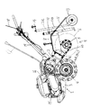
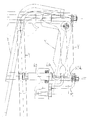
図1は歩行型耕耘機の側面図であり、耕耘機の機体1は、側面視へ字型に形成されたミッションケース2と該ミッションケース2の前側に設ける支持フレーム3等を備える。このうちミッションケース2の前側ケース2a下部には車軸4を突設し左右走行車輪4L,4Rを支持し、後側ケース2b下部には耕耘軸5を突設して耕耘爪6,6…を設けて耕耘装置7を構成する。
FIG. 1 is a side view of a walking type tiller. A
耕耘装置7の上面はロータリカバー8で覆う構成であり、後面は後部カバー9で覆う構成としている。ロータリカバー8の後端側にはホルダ10を備え、抵抗棒11を高さ調節自在に連結保持している。この抵抗棒ホルダ10に尾輪ホルダ12aを連結一体的に設け、2重筒軸の伸縮軸12bを介して尾輪13を上下高さ調節自在に設けている。14は尾輪高さ調節用ハンドルで、これを操作することによって尾輪ホルダ12aに対する伸縮軸12bの突出長さが変わって尾輪13の高さを調節できる。
The top surface of the tillage device 7 is configured to be covered with a rotary cover 8, and the rear surface is configured to be covered with a rear cover 9. A
前記支持フレーム3にはエンジン15を設け、ベルト伝動機構Bを介してエンジン出力をミッションケース2内伝動機構に伝達する構成である。16はベルト伝動機構を覆うベルトカバーである。
The support frame 3 is provided with an
前記ミッションケース2の上部において、操作ハンドル17の基部を装着し、該ハンドル17は後方斜め上方に向けて設けられ、平面視ループ状に形成されている。18はクラッチレバーで、横軸19回りの上下回動によって前記ベルト伝動機構部に構成する走行クラッチ(図示せず)を入り切りに連動可能の構成であり、このクラッチレバー18を操作ハンドル17の把持部と重なる状態に押下げるときはクラッチ「入」となり、手を離すと図外バネの復帰付勢力でクラッチを「切」となす構成である。
At the upper part of the
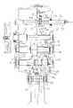
ついでミッションケース2内伝動構成について説明する。
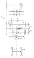
21はエンジン15からの動力をベルト伝動機構Bで伝動される入力軸で、入力軸21の軸心上には、低速・後進用ギヤ部22a及び中速・高速用ギヤ部22bを一体形成し、かつ入力軸21に沿って摺動可能な走行変速ギヤ22と、幅広の第一耕耘伝動ギヤ23とを設けている。走行変速ギヤ22と幅広の第一耕耘伝動ギヤ23は入力軸21と一体となって回転する構成である。
Next, the transmission configuration in the
25は走行第一軸で、走行第一軸25の軸心上には中速ギヤ26と、高速ギヤ27と、低速ギヤ28と、第一走行伝動ギヤ29と、第三走行伝動ギヤ37とを設け、高速ギヤ27と第一走行伝動ギヤ29と第三走行伝動ギヤ37とは走行第一軸25と共に回転する構成で、中速ギヤ26と低速ギヤ28は走行第一軸25に対して遊転する構成である。
30は走行第二軸で、走行第二軸30の軸心上には耕耘爪の伝動を入り切りする第二耕耘伝動ギヤ31と、中速用カウンタギヤ32と、低速用カウンタギヤ33と、後進ギヤ34と、第二走行伝動ギヤ35とを設け、第二耕耘伝動ギヤ31は走行第二軸30に対して遊転する構成でかつ走行第二軸30に沿って摺動する構成とし、中速用カウンタギヤ32と、低速用カウンタギヤ33と、後進ギヤ34と、第二走行伝動ギヤ35は走行第二軸30と共に回転する構成としている。
中速ギヤ26は走行変速ギヤ22と噛合う第一中速伝動ギヤ部26aと、中速用カウンタギヤ32と噛合う第二中速伝動ギヤ26bとを一体形成する構成である。また、低速ギヤ28は走行変速ギヤ22と噛合う第一低速伝動ギヤ部28aと、低速用カウンタギヤ33と噛合う第二低速伝動ギヤ28bとを一体形成する構成である。また、低速用カウンタギヤ33と後進ギヤ34と第二走行伝動ギヤ35は一体形成する構成である。また、第二走行伝動ギヤ35と第一走行伝動ギヤ29とが噛合う構成としている。
The
40は走行第三軸で、走行第二軸40の軸心上には第四走行伝動ギヤ41と、走行車輪に動力を伝動するための駆動スプロケット42とを設け、第四走行伝動ギヤ41と駆動スプロケット42は走行第三軸40と共に回転する構成としている。そして、第三走行伝動ギヤ35と第四走行伝動ギヤ41とは噛合う構成としている。
次に、走行変速ギヤ22と第二耕耘伝動ギヤ31とを移動させる構成について説明する。
50は走行変速ギヤ22を摺動して移動させるための走行変速シフタステー50で長軸状に形成している。そして、その一端をミッションケース2内部に設け、途中部をミッションケース2から突出し、他端をミッションケース2外部に位置するよう設け、長手方向に移動可能に構成している。
Next, a configuration for moving the traveling
走行変速シフタステー50の途中部には位置決め用溝部51a〜51eを複数個所設け、スプリング52で付勢された位置決め具53が位置決め用溝部51a〜51eの何れかに挿入することで走行変速シフタステー50が所定の位置で位置決めできる構成としている。また、走行変速シフタステー50の途中部にはシフタ54を一体形成し、走行変速ギヤ22に当接する構成としている。また、走行変速シフタステー50の他端部には走行変速シフタステー50を操作するシフタ操作レバーYが係脱する操作溝部55を形成している。
A plurality of positioning groove portions 51a to 51e are provided in the middle of the traveling
60は第二耕耘伝動ギヤ31を摺動させるための耕耘入切シフタステーで、走行変速シフタステー50と同様、その一端をミッションケース2内部に設け、途中部がミッションケース2から突出し、他端がミッションケース2の外部に設け、長手方向に移動可能に構成している。そして、走行変速シフタステー50に隣接する位置に並行して設けている。そして、耕耘入切シフタステー60の他端部には、耕耘入切シフタステー60を操作するシフタ操作レバーYが係脱する操作溝部61a、61bを左右方向に隣接して二箇所形成している。そして、耕耘入切シフタステー60にも図示しないがシフタを形成し、第二耕耘伝動ギヤ31に当接して摺動させる構成としている。
60 is a tiller on / off shifter stay for sliding the second
Mはシフタ操作レバーYを耕耘入切シフタステー60の操作溝部61a、61bに案内する案内部材で平面視略m型に形成している。また、シフタ操作レバーYはその一端を機体前後方向後ろ斜め上方に向かって延設し、途中部を後述する案内溝70を通過し、他端を図10に示すようにコの字型に屈曲して形成し、走行変速シフタステー50の操作溝部55又は耕耘入切シフタステーの操作溝部61a、61bに係合する構成としている。
M is a guide member that guides the shifter operation lever Y to the operation groove portions 61a and 61b of the tiller-on / off
次にシフタ操作レバーYの操作方法について説明する。
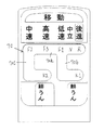
70はシフタ操作レバーYを案内する案内溝で、案内溝は後進R・中立N・低速F1・高速F3・中速F2の各位置を選択する走行変速案内溝部70aと、耕耘作業の入り切りを行なう耕耘入切案内溝部70b,70cとから構成し、走行変速案内溝部70aは左右方向に中速F2・高速F3・低速F1・中立N・後進Rの順に直列して形成し、耕耘入切案内溝部70b,70cは走行低速F1から分岐する低速耕耘入切案内溝部70bと中速F2から分岐する中速耕耘入切案内溝部70cとをそれぞれ走行変速案内溝部70aから交差する方向に形成し、耕耘入切案内溝部70b,70cは平面視略L字状に形成している。
Next, an operation method of the shifter operation lever Y will be described.
次に走行変速の伝動の作用について説明する。
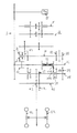
低速で走行するときは、走行変速シフタステー50の操作溝部55に係合したシフタ操作レバーYを走行変速案内溝70aの低速位置F1に操作すると、走行変速シフタステー50が移動し、位置決め溝部51の低速の溝部51cに位置決め具53が係合され、走行変速シフタステー50の位置決めがなされる。また同時に、シフタ54が走行変速ギヤ22を移動させ、低速・後進用ギヤ部22aが低速ギヤ28の第一低速伝動ギヤ部28aと噛合うことで入力軸21の動力が伝動される。そして、第二低速伝動ギヤ部28b、低速用カウンタギヤ33、第二走行伝動ギヤ35、第一走行伝動ギヤ29、第三走行伝動ギヤ37、第四走行伝動ギヤ41、走行スプロケット42の順に伝動し、走行車輪4L,4Rが低速で走行する。なお、低速の伝動構成は図3に示している。
Next, a description will be given of the operation of transmission for traveling speed change.
When traveling at a low speed, when the shifter operation lever Y engaged with the
高速で走行するときは走行変速シフタステー50の操作溝部55に係合したシフタ操作レバーYを走行変速案内溝70aの高速位置F3に操作する。すると走行変速シフタステー50が移動し、位置決め溝部51の高速の溝部51dに位置決め具53が係合され、走行変速シフタステー50の位置決めがなされる。また同時に、シフタ54が走行変速ギヤ22を移動させ、中速・高速用ギヤ部22bが高速ギヤ27と噛合うことで入力軸21の動力が伝動される。そして、第三走行伝動ギヤ37、第四走行伝動ギヤ41、走行スプロケット42の順に伝動し、走行車輪4L,4Rが高速で走行する。なお、高速の伝動構成は図5に示している。
When traveling at a high speed, the shifter operating lever Y engaged with the
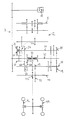
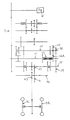
中速で走行するときは、走行変速シフタステー50の操作溝部55に係合したシフタ操作レバーYを走行変速案内溝70aの中速位置F2に操作すると、走行変速シフタステー50が移動し、位置決め溝部51の中速の溝部51eに位置決め具53が係合され、走行変速シフタステー50の位置決めがなされる。また同時に、シフタ54が走行変速ギヤ22を移動させ、中速・高速用ギヤ部22bが中速ギヤ26の第一低速伝動ギヤ部26aと噛合うことで入力軸21の動力が伝動される。そして、第二低速伝動ギヤ部26b、中速用カウンタギヤ32、第二走行伝動ギヤ35、第一走行伝動ギヤ29、第三走行伝動ギヤ37、第四走行伝動ギヤ41、走行スプロケット42の順に伝動し、走行車輪4L,4Rが中速で走行する。なお、中速の伝動構成は図4に示している。
When traveling at medium speed, when the shifter operation lever Y engaged with the
低速で耕耘作業を行なうときには走行変速案内溝70aの低速位置F1から耕耘入切案内溝部70bに向かってシフタ操作レバーYを走行変速案内溝70aに対して交差する方向に操作すると、シフタ操作レバーYが走行変速シフタステー50の操作溝部55を離れて操作溝部61aに係合され、次いで、シフタ操作レバーYを走行変速案内溝70aと並行する方向の終端部K1位置まで操作すると、耕耘入切シフタステー60のシフタ(図示せず)が第二耕耘機伝動ギヤ31を耕耘切りの状態(実線ロ)から耕耘入りの状態に移動させて(破線イ)、耕耘伝動機構Qを経て耕耘軸5が回転駆動し、耕耘爪6による耕耘作業が行なわれる。
When plowing is performed at a low speed, if the shifter operation lever Y is operated in a direction intersecting the travel
中速で耕耘作業を行なうときには走行変速案内溝70aの中速位置F2から耕耘入切案内溝部70cに向かってシフタ操作レバーYを走行変速案内溝70aに対して交差する方向に操作すると、シフタ操作レバーYが走行変速シフタステー50の操作溝部55を離れて操作溝部61bに係合され、次いで、シフタ操作レバーYを走行変速案内溝70aと並行する方向の終端部K2位置まで操作すると、耕耘入切シフタステー60のシフタ(図示せず)が第二耕耘機伝動ギヤ31を耕耘切りの状態(実線二)から耕耘入りの状態に移動させて(破線ハ)、耕耘伝動機構Qを経て耕耘軸5が回転駆動し、耕耘爪6による耕耘作業が行なわれる。
When plowing work is performed at medium speed, if the shifter operation lever Y is operated in the direction intersecting the traveling
後進で走行するときは走行変速シフタステー50の操作溝部55に係合したシフタ操作レバーYを走行変速案内溝70aの後進位置Rに操作する。すると走行変速シフタステー50が移動し、中立の位置決め溝部51bを通過して後進の位置決め溝部51aに位置決め具53が係合され、走行変速シフタステー50の位置決めがなされる。また同時に、シフタ54が走行変速ギヤ22を移動させ、低速・後進用ギヤ部22aが後進ギヤ27と噛合うことで入力軸21の動力が伝動される。そして、第二走行伝動ギヤ35、第一走行伝動ギヤ29、第三走行伝動ギヤ37、第四走行伝動ギヤ41、走行スプロケット42の順に伝動し、走行車輪4L,4Rが後進で走行する。
When traveling in reverse, the shifter operating lever Y engaged with the
本実施の形態の効果について以下説明する。
本実施の形態によると、低速F1と中速F2からそれぞれ耕耘作業の入り切りを行なうことができるため、異なる速度による耕耘作業を行なうことができ、状態の異なる圃場に適した耕耘作業を行なうことができる。また、一本のシフタ操作レバーYで走行の変速及び耕耘作業の入り切りを行なうため簡単な構成及び操作で行なうことができる。また、シフタ操作レバーYの誤操作で、低速の耕耘作業中に中速の耕耘作業に移行したり、中速の耕耘作業から低速の耕耘作業に移行することがないため、安全な耕耘作業を行なうことができる。
The effect of this embodiment will be described below.
According to the present embodiment, the tilling work can be turned on and off from the low speed F1 and the medium speed F2, respectively. Therefore, the tilling work at different speeds can be performed, and the tilling work suitable for the field having different states can be performed. it can. In addition, since a single shifter operating lever Y is used to shift the traveling and turn on and off the tillage work, it can be performed with a simple configuration and operation. In addition, the shifter operation lever Y is not operated erroneously, so that there is no need to shift to medium speed tillage during low speed tillage or to shift from medium speed tillage to low speed tillage. be able to.
また、低速F1と中速F2との間に高速F3の操作位置を設けることで、低速耕耘入切案内溝部70bと中速耕耘入切案内溝部70cを設定間隔で離して設けることができるため、作業者が耕耘位置を案内溝70を目視しやすくシフタ操作レバーYを操作しやすい。さらに、ミッションケース2内において高速ギヤ27を中速ギヤ26と低速ギヤ28との間に配置することができるためミッションケース22全体をコンパクトにすることができる。
Further, by providing the operation position of the high speed F3 between the low speed F1 and the medium speed F2, the low speed tillage on / off guide groove part 70b and the medium speed tillage on / off guide groove part 70c can be provided apart at a set interval, It is easy for the operator to visually check the
4L (左)走行車輪
4R (右)走行車輪
6 耕耘爪
22 走行変速ギヤ(22)
31 (第二)耕耘伝動ギヤ
50 走行変速シフタステー
54 シフタ
55 操作溝部
60 耕耘入切シフタステー
61a(低速)第一操作溝部
61b(中速)第二操作溝部
70 案内溝
70a 走行変速案内溝部
70b(低速)第一耕耘入切案内溝部
70c(中速)第二耕耘入切案内溝部
F1 第一速(低速)
F2 第二速(中速)
Y シフタ操作レバー
イ 駆動入位置
ロ 駆動切位置
4L (Left) Traveling
31 (Second)
F2 2nd speed (medium speed)
Y Shifter operation lever i Drive-in position B Drive-off position
Claims (1)
走行シフタステー(50)には、高速・中速・低速・中立・後進用の位置決め用溝部(51a〜51e)を設けると共に、シフタ操作レバー(Y)を係脱させる操作溝部(55)を設け、
走行シフタステー(50)の位置決め用溝部(51a〜51e)の内、高速用の位置決め用溝部(51d)を中速用の位置決め溝部(51e)と低速用の位置決め溝部(51c)の間に形成し、
耕耘入切シフタステー(60)には、シフタ操作レバー(Y)を係脱させる低速用の操作溝部(61a)と中速用の操作溝部(61b)を設け、
走行変速シフタステー(50)と耕耘シフタステー(60)を隣接位置に並行して設け、それぞれ長手方向に移動可能に構成し、
走行シフタステー(50)を低速用の位置決め溝部(51c)に位置決めした状態でシフタ操作レバー(Y)を走行シフタステー(50)から交差する方向に操作すると、シフタ操作レバー(Y)が走行シフタステー(50)の操作溝部(55)から耕耘入切シフタステー(60)の低速用の案内溝部(61a)に係合し、耕耘入切シフタステー(60)を移動操作可能に構成し、
走行シフタステー(50)を中速用の位置決め溝部(51e)に位置決めした状態でシフタ操作レバー(Y)を走行シフタステー(50)から交差する方向に操作すると、シフタ操作レバー(Y)が走行シフタステー(50)の操作溝部(55)から耕耘入切シフタステー(60)の中速用の案内溝部(61b)に係合し、耕耘入切シフタステー(60)を移動操作可能に構成したことを特徴とする耕耘機。 Traveling wheels (4L, 4R), tilling claws (6) for cultivating the field, and traveling speed change gears (22) for shifting the traveling speed of the traveling wheels (4L, 4R) to low speed (F1) or medium speed (F2). A tilling transmission gear (31) for turning the tilling claw (6) on and off, a traveling speed shifter stay (50) for moving the traveling transmission gear (22) to a predetermined speed position, and a tilling transmission gear (31). A tiller on / off shifter stay (60) that moves to a drive on position and a drive off position, a shifter operation lever (Y) that operates to move the travel shift shifter stay (50) and the tiller on / off shifter stay (60), and the shifter operation A guide groove (70) for guiding the movement of the lever (Y) is provided, and an operation groove portion (Y) that allows the shifter operation lever (Y) to be engaged with and disengaged from the traveling shift shifter stay (50) and the tilling on / off shifter stay (60) ( 55 61a, 61b) and is provided, the guide grooves (70) and the traveling speed change guide groove for guiding the gear shift operation to the low speed (F1) or medium speed (F2) (70a), tilling on-off to guide the on-off operation of the tilling A first tilling / cutting guide groove formed by branching from the position of the low speed (F1) of the traveling transmission guide groove (70a), which is constituted by the guide groove (70b, 70c). (70b) and a second tillage on / off guide groove portion (70c) formed by branching from the position of the medium speed (F2) of the traveling transmission guide groove portion (70a) ,
The travel shifter stay (50) is provided with positioning grooves (51a to 51e) for high speed, medium speed, low speed, neutral and reverse, and an operation groove (55) for engaging and disengaging the shifter operation lever (Y).
Of the positioning groove portions (51a to 51e) of the travel shifter stay (50), a high-speed positioning groove portion (51d) is formed between the medium-speed positioning groove portion (51e) and the low-speed positioning groove portion (51c). ,
The tiller on / off shifter stay (60) is provided with a low speed operation groove (61a) and a medium speed operation groove (61b) for engaging and disengaging the shifter operation lever (Y).
The traveling shift shifter stay (50) and the tillage shifter stay (60) are provided in parallel in adjacent positions, and are configured to be movable in the longitudinal direction,
When the shifter operating lever (Y) is operated in a direction intersecting the traveling shifter stay (50) with the traveling shifter stay (50) positioned in the low-speed positioning groove (51c), the shifter operating lever (Y) is moved to the traveling shifter stay (50). ) Is engaged with the low-speed guide groove portion (61a) of the tilling on / off shifter stay (60) from the operation groove portion (55), and the tilling on / off shifter stay (60) is configured to be movable.
When the shifter operation lever (Y) is operated in a direction intersecting the travel shifter stay (50) with the travel shifter stay (50) positioned in the medium speed positioning groove (51e), the shifter operation lever (Y) is moved to the travel shifter stay (50). The operation groove portion (55) of 50) is engaged with the medium speed guide groove portion (61b) of the tilling on / off shifter stay (60), and the tilling on / off shifter stay (60) is configured to be movable. Cultivator.
Priority Applications (1)
| Application Number | Priority Date | Filing Date | Title |
|---|---|---|---|
| JP2007336888A JP5200529B2 (en) | 2007-12-27 | 2007-12-27 | Cultivator |
Applications Claiming Priority (1)
| Application Number | Priority Date | Filing Date | Title |
|---|---|---|---|
| JP2007336888A JP5200529B2 (en) | 2007-12-27 | 2007-12-27 | Cultivator |
Related Child Applications (1)
| Application Number | Title | Priority Date | Filing Date |
|---|---|---|---|
| JP2011145971A Division JP5360142B2 (en) | 2011-06-30 | 2011-06-30 | Cultivator |
Publications (2)
| Publication Number | Publication Date |
|---|---|
| JP2009153474A JP2009153474A (en) | 2009-07-16 |
| JP5200529B2 true JP5200529B2 (en) | 2013-06-05 |
Family
ID=40958175
Family Applications (1)
| Application Number | Title | Priority Date | Filing Date |
|---|---|---|---|
| JP2007336888A Expired - Fee Related JP5200529B2 (en) | 2007-12-27 | 2007-12-27 | Cultivator |
Country Status (1)
| Country | Link |
|---|---|
| JP (1) | JP5200529B2 (en) |
Families Citing this family (1)
| Publication number | Priority date | Publication date | Assignee | Title |
|---|---|---|---|---|
| JP5743727B2 (en) * | 2011-06-08 | 2015-07-01 | 三菱農機株式会社 | Walking type agricultural machine |
Family Cites Families (4)
| Publication number | Priority date | Publication date | Assignee | Title |
|---|---|---|---|---|
| JP2690881B2 (en) * | 1995-09-22 | 1997-12-17 | ヤンマー農機株式会社 | Speed change operation device such as cultivator |
| JP3548128B2 (en) * | 2001-03-22 | 2004-07-28 | ヤンマー農機株式会社 | Tiller speed changer |
| JP2005308076A (en) * | 2004-04-21 | 2005-11-04 | Mitsubishi Agricult Mach Co Ltd | Sub speed change mechanism in transmission of working vehicle |
| JP4525300B2 (en) * | 2004-10-29 | 2010-08-18 | 井関農機株式会社 | Manufacturing method of walking type tillage machine |
-
2007
- 2007-12-27 JP JP2007336888A patent/JP5200529B2/en not_active Expired - Fee Related
Also Published As
| Publication number | Publication date |
|---|---|
| JP2009153474A (en) | 2009-07-16 |
Similar Documents
| Publication | Publication Date | Title |
|---|---|---|
| US4519459A (en) | Power drive rear tine tiller with reversing gear transmission for the tines | |
| JP5319609B2 (en) | Shifting operation structure of paddy field machine | |
| JP5200529B2 (en) | Cultivator | |
| JP4236166B2 (en) | Agricultural machine | |
| JP5360142B2 (en) | Cultivator | |
| JP6129086B2 (en) | Walking type work machine | |
| JP6247098B2 (en) | Walking mower | |
| JP5341822B2 (en) | Work machine transmission structure | |
| JP2009201486A (en) | Tiller | |
| JP2658016B2 (en) | Transmission operating device for cultivator | |
| JP4274969B2 (en) | Rice transplanter | |
| JP5709420B2 (en) | Mowing machine | |
| JP4512563B2 (en) | Mobile farm machine | |
| JP5743727B2 (en) | Walking type agricultural machine | |
| JP4368772B2 (en) | Management machine | |
| CN213073518U (en) | Multi-gear miniature tiller | |
| JP2013147145A (en) | Management machine | |
| JP6467269B2 (en) | Agricultural machine | |
| JPS5854257Y2 (en) | Transmission device in rice transplanter | |
| JP4658338B2 (en) | Shifting device for management machine | |
| JP3680960B2 (en) | Partially reverse rotary tiller | |
| JP5205334B2 (en) | Walking type agricultural machine | |
| JP4139275B2 (en) | Farm machine operating mechanism | |
| KR100823426B1 (en) | Clutch assembly for walking mower | |
| JPS5838423Y2 (en) | Transmission device for drive output of agricultural machinery |
Legal Events
| Date | Code | Title | Description |
|---|---|---|---|
| A621 | Written request for application examination |
Free format text: JAPANESE INTERMEDIATE CODE: A621 Effective date: 20101221 |
|
| A977 | Report on retrieval |
Free format text: JAPANESE INTERMEDIATE CODE: A971007 Effective date: 20120321 |
|
| A131 | Notification of reasons for refusal |
Free format text: JAPANESE INTERMEDIATE CODE: A131 Effective date: 20120403 |
|
| A521 | Request for written amendment filed |
Free format text: JAPANESE INTERMEDIATE CODE: A523 Effective date: 20120604 |
|
| TRDD | Decision of grant or rejection written | ||
| A01 | Written decision to grant a patent or to grant a registration (utility model) |
Free format text: JAPANESE INTERMEDIATE CODE: A01 Effective date: 20130115 |
|
| A61 | First payment of annual fees (during grant procedure) |
Free format text: JAPANESE INTERMEDIATE CODE: A61 Effective date: 20130128 |
|
| R150 | Certificate of patent or registration of utility model |
Ref document number: 5200529 Country of ref document: JP Free format text: JAPANESE INTERMEDIATE CODE: R150 Free format text: JAPANESE INTERMEDIATE CODE: R150 |
|
| FPAY | Renewal fee payment (event date is renewal date of database) |
Free format text: PAYMENT UNTIL: 20160222 Year of fee payment: 3 |
|
| LAPS | Cancellation because of no payment of annual fees |