JP5197624B2 - Improved laser and ultrasonic inspection using infrared thermography - Google Patents
Improved laser and ultrasonic inspection using infrared thermography Download PDFInfo
- Publication number
- JP5197624B2 JP5197624B2 JP2009540331A JP2009540331A JP5197624B2 JP 5197624 B2 JP5197624 B2 JP 5197624B2 JP 2009540331 A JP2009540331 A JP 2009540331A JP 2009540331 A JP2009540331 A JP 2009540331A JP 5197624 B2 JP5197624 B2 JP 5197624B2
- Authority
- JP
- Japan
- Prior art keywords
- target
- ultrasonic
- laser
- inspection
- target material
- Prior art date
- Legal status (The legal status is an assumption and is not a legal conclusion. Google has not performed a legal analysis and makes no representation as to the accuracy of the status listed.)
- Expired - Fee Related
Links
- 238000007689 inspection Methods 0.000 title claims description 116
- 238000001931 thermography Methods 0.000 title claims description 27
- 239000013077 target material Substances 0.000 claims description 55
- 238000002604 ultrasonography Methods 0.000 claims description 54
- 239000002131 composite material Substances 0.000 claims description 52
- 238000000034 method Methods 0.000 claims description 38
- 238000006073 displacement reaction Methods 0.000 claims description 32
- 238000001514 detection method Methods 0.000 claims description 29
- 238000012545 processing Methods 0.000 claims description 22
- 230000001052 transient effect Effects 0.000 claims description 19
- 230000003287 optical effect Effects 0.000 claims description 15
- 238000012360 testing method Methods 0.000 claims description 11
- 230000008859 change Effects 0.000 claims description 7
- 230000008569 process Effects 0.000 claims description 6
- 238000000926 separation method Methods 0.000 claims description 3
- 230000001678 irradiating effect Effects 0.000 claims 2
- 235000013372 meat Nutrition 0.000 claims 1
- 238000003384 imaging method Methods 0.000 description 13
- 230000007547 defect Effects 0.000 description 10
- 238000010586 diagram Methods 0.000 description 10
- 238000003331 infrared imaging Methods 0.000 description 10
- 238000004458 analytical method Methods 0.000 description 7
- 238000004519 manufacturing process Methods 0.000 description 7
- 239000000463 material Substances 0.000 description 7
- 229920000642 polymer Polymers 0.000 description 6
- 230000008878 coupling Effects 0.000 description 5
- 238000010168 coupling process Methods 0.000 description 5
- 238000005859 coupling reaction Methods 0.000 description 5
- 239000011159 matrix material Substances 0.000 description 5
- 230000001066 destructive effect Effects 0.000 description 4
- 239000000835 fiber Substances 0.000 description 3
- 230000006870 function Effects 0.000 description 3
- 230000007246 mechanism Effects 0.000 description 3
- 239000002184 metal Substances 0.000 description 3
- 229910052751 metal Inorganic materials 0.000 description 3
- 230000005855 radiation Effects 0.000 description 3
- 238000012285 ultrasound imaging Methods 0.000 description 3
- 230000000007 visual effect Effects 0.000 description 3
- 238000005094 computer simulation Methods 0.000 description 2
- 238000011156 evaluation Methods 0.000 description 2
- 238000005259 measurement Methods 0.000 description 2
- 229920013657 polymer matrix composite Polymers 0.000 description 2
- 239000011160 polymer matrix composite Substances 0.000 description 2
- 230000004044 response Effects 0.000 description 2
- 239000000523 sample Substances 0.000 description 2
- 238000010521 absorption reaction Methods 0.000 description 1
- 238000013459 approach Methods 0.000 description 1
- 230000015572 biosynthetic process Effects 0.000 description 1
- 238000001816 cooling Methods 0.000 description 1
- 238000000354 decomposition reaction Methods 0.000 description 1
- 230000032798 delamination Effects 0.000 description 1
- 238000002592 echocardiography Methods 0.000 description 1
- 230000000694 effects Effects 0.000 description 1
- 230000005284 excitation Effects 0.000 description 1
- 238000001914 filtration Methods 0.000 description 1
- 238000005206 flow analysis Methods 0.000 description 1
- 238000005286 illumination Methods 0.000 description 1
- 230000001939 inductive effect Effects 0.000 description 1
- 150000002739 metals Chemical class 0.000 description 1
- 238000012986 modification Methods 0.000 description 1
- 230000004048 modification Effects 0.000 description 1
- 238000009659 non-destructive testing Methods 0.000 description 1
- 239000013307 optical fiber Substances 0.000 description 1
- 238000010248 power generation Methods 0.000 description 1
- 238000003908 quality control method Methods 0.000 description 1
- 238000001454 recorded image Methods 0.000 description 1
- 239000007787 solid Substances 0.000 description 1
- 230000003068 static effect Effects 0.000 description 1
- 238000006467 substitution reaction Methods 0.000 description 1
Images


Classifications
-
- G—PHYSICS
- G01—MEASURING; TESTING
- G01N—INVESTIGATING OR ANALYSING MATERIALS BY DETERMINING THEIR CHEMICAL OR PHYSICAL PROPERTIES
- G01N29/00—Investigating or analysing materials by the use of ultrasonic, sonic or infrasonic waves; Visualisation of the interior of objects by transmitting ultrasonic or sonic waves through the object
- G01N29/22—Details, e.g. general constructional or apparatus details
- G01N29/24—Probes
- G01N29/2418—Probes using optoacoustic interaction with the material, e.g. laser radiation, photoacoustics
-
- G—PHYSICS
- G01—MEASURING; TESTING
- G01N—INVESTIGATING OR ANALYSING MATERIALS BY DETERMINING THEIR CHEMICAL OR PHYSICAL PROPERTIES
- G01N29/00—Investigating or analysing materials by the use of ultrasonic, sonic or infrasonic waves; Visualisation of the interior of objects by transmitting ultrasonic or sonic waves through the object
- G01N29/22—Details, e.g. general constructional or apparatus details
-
- G—PHYSICS
- G01—MEASURING; TESTING
- G01N—INVESTIGATING OR ANALYSING MATERIALS BY DETERMINING THEIR CHEMICAL OR PHYSICAL PROPERTIES
- G01N25/00—Investigating or analyzing materials by the use of thermal means
- G01N25/72—Investigating presence of flaws
-
- G—PHYSICS
- G01—MEASURING; TESTING
- G01N—INVESTIGATING OR ANALYSING MATERIALS BY DETERMINING THEIR CHEMICAL OR PHYSICAL PROPERTIES
- G01N29/00—Investigating or analysing materials by the use of ultrasonic, sonic or infrasonic waves; Visualisation of the interior of objects by transmitting ultrasonic or sonic waves through the object
- G01N29/22—Details, e.g. general constructional or apparatus details
- G01N29/228—Details, e.g. general constructional or apparatus details related to high temperature conditions
-
- G—PHYSICS
- G01—MEASURING; TESTING
- G01N—INVESTIGATING OR ANALYSING MATERIALS BY DETERMINING THEIR CHEMICAL OR PHYSICAL PROPERTIES
- G01N29/00—Investigating or analysing materials by the use of ultrasonic, sonic or infrasonic waves; Visualisation of the interior of objects by transmitting ultrasonic or sonic waves through the object
- G01N29/22—Details, e.g. general constructional or apparatus details
- G01N29/24—Probes
-
- G—PHYSICS
- G01—MEASURING; TESTING
- G01N—INVESTIGATING OR ANALYSING MATERIALS BY DETERMINING THEIR CHEMICAL OR PHYSICAL PROPERTIES
- G01N2291/00—Indexing codes associated with group G01N29/00
- G01N2291/02—Indexing codes associated with the analysed material
- G01N2291/023—Solids
- G01N2291/0231—Composite or layered materials
-
- G—PHYSICS
- G01—MEASURING; TESTING
- G01N—INVESTIGATING OR ANALYSING MATERIALS BY DETERMINING THEIR CHEMICAL OR PHYSICAL PROPERTIES
- G01N2291/00—Indexing codes associated with group G01N29/00
- G01N2291/02—Indexing codes associated with the analysed material
- G01N2291/028—Material parameters
- G01N2291/02881—Temperature
Description
本発明は、非破壊試験に関し、更に詳しくは、材料の内部構造を検査するために赤外線画像および超音波試験を使うことに関する。 The present invention relates to non-destructive testing, and more particularly to using infrared imaging and ultrasonic testing to inspect the internal structure of materials.
近年、複合構造物を使うことが航空宇宙、自動車、およびその他多くの営利産業で甚だしい成長を見せている。複合材料は、性能でかなりの改善を示すが、それらは、製造工程および完成品での使用中の両方で厳密な品質管理手順が要求される。特に、非破壊評価(NED)法によって複合材料の構造的完全性を評価しなければならない。適正な評価には、表面領域近くおよび深内部領域の両方で含有物、層間剥離および有孔性を検出する能力が必要である。 In recent years, the use of composite structures has seen tremendous growth in aerospace, automotive, and many other commercial industries. Although composite materials show significant improvements in performance, they require strict quality control procedures both during the manufacturing process and during use in the finished product. In particular, the structural integrity of the composite material must be evaluated by the non-destructive evaluation (NED) method. Proper evaluation requires the ability to detect inclusions, delamination and porosity both near the surface area and in deep internal areas.
複合材料の構造的完全性を評価するために種々の方法および装置が提案されている。或る解決法は、目標材料に超音波表面変位を生成するために超音波源を使う。次にこの超音波表面変位を測定し且つ解析する。この超音波源は、目標に向けたパルス式生成レーザビームでもよい。別の検出レーザからのレーザ光をこの被検査物の超音波表面変位によって散乱させる。次に収集光学装置が散乱したレーザエネルギーを収集する。この収集光学装置は、干渉計またはその他の装置に接続してあり、この複合構造物の構造的完全性についてのデータをこの散乱したレーザエネルギーの解析によって得ることができる。レーザ超音波は、製造工程中の部品の検査に非常に効果的であることを示している。 Various methods and apparatus have been proposed for assessing the structural integrity of composite materials. One solution uses an ultrasonic source to generate an ultrasonic surface displacement in the target material. This ultrasonic surface displacement is then measured and analyzed. The ultrasound source may be a pulsed generated laser beam aimed at the target. Laser light from another detection laser is scattered by the ultrasonic surface displacement of the inspection object. The collection optics then collects the scattered laser energy. The collection optics is connected to an interferometer or other device, and data about the structural integrity of the composite structure can be obtained by analysis of the scattered laser energy. Laser ultrasound has been shown to be very effective in inspecting parts during the manufacturing process.
典型的に、レーザ源は、表面上の局部スポットで熱膨張によって音を生成し、一方、干渉計に接続した、プローブレーザビームは表面変位または速度を検出する。生成レーザの吸収によるこの熱膨張は、変位を生じ、それをこのレーザ・超音波検出システムによって復調し、このレーザ・超音波信号の最初にパルスを出す結果となる。このエコーを普通表面エコーと呼ぶ。この表面エコーは、試料表面近くの欠陥によって生じたあらゆるエコーを隠すかも知れない。この表面エコーの持続時間は、生成レーザパルス持続時間およびこの検出システムの周波数帯域幅に依存する。典型的に、CO2生成レーザおよび検出用共焦点ファブリ・ペローでは、表面エコーが数マイクロセカンドまで持続するかも知れない。それでその時間中にエコーを作るあらゆる欠陥が隠されるかも知れない。レーザ・超音波検出は、深内部欠陥に敏感であり、近表面欠陥に鈍感である。 Typically, a laser source generates sound by thermal expansion at a local spot on the surface, while a probe laser beam connected to an interferometer detects surface displacement or velocity. This thermal expansion due to absorption of the generated laser results in a displacement that is demodulated by the laser and ultrasound detection system and results in a pulse at the beginning of the laser and ultrasound signal. This echo is usually called a surface echo. This surface echo may mask any echo caused by defects near the sample surface. The duration of this surface echo depends on the generated laser pulse duration and the frequency bandwidth of the detection system. Typically, in a CO2 generating laser and a detecting confocal Fabry-Perot, the surface echo may last up to a few microseconds. So any flaws that make echoes during that time may be hidden. Laser / ultrasonic detection is sensitive to deep internal defects and insensitive to near surface defects.
もう一つのNDE法である、過渡現象赤外線(IR)サーモグラフィは、高分子マトリックス部品で数ミリより深い欠陥に鈍感であるために高分子マトリックス複合材の検査を効率的に可能にすることはない。 Another NDE method, Transient Infrared (IR) thermography, is insensitive to defects deeper than a few millimeters in polymer matrix components and therefore does not efficiently allow inspection of polymer matrix composites. .
本発明の実施例は、上に特定した要求におよびその他の要求にも同様に実質的に取組むシステムおよび方法に関する。本発明の実施例を以下の記述および請求項で更に詳しく説明する。本発明の実施例の利点および特徴は、この説明、添付の図面および請求項から明白になるだろう。 Embodiments of the invention relate to systems and methods that substantially address the above-identified requirements and other requirements as well. Embodiments of the invention are described in further detail in the following description and claims. The advantages and features of embodiments of the present invention will become apparent from the description, the accompanying drawings, and the claims.
本発明の実施例は、上に特定した要求におよびその他の要求にも同様に実質的に取組むためにレーザ・超音波と赤外線画像技術を組合わせる。レーザ超音波生成技術を使って過渡熱源を提供してもよい。それで、過渡現象赤外線(IR)サーモグラフィをレーザ超音波と組合わせて高分子マトリックス部品(即ち、複合材料)のより完全な非破壊検査を提供してもよい。
或る実施例は、目標材料の近表面および深内部構造を検査するための検査システムを提供する。この検査システムは、超音波検査システムとサーモグラフィ検査システムを組合わせる。このサーモグラフィ検査システムを超音波検査システムに取付けてレーザ超音波検査と両立する距離で目標材料のサーモグラフィ検査ができるように修正する。目標材料上に深部赤外線(IR)イメージングを使って定量的情報を得る。このIRイメージングおよびレーザ・超音波結果を組合わせて複雑な形状の複合材の3次元投影法で投影する。このサーモグラフィの結果がレーザ・超音波結果を補足して、特に目標材料が薄い複合部品であるときに、より完全でより信頼性のある、目標材料の内部構造についての情報をもたらす。
Embodiments of the present invention combine laser and ultrasound and infrared imaging techniques to substantially address the above-identified requirements and other requirements as well. Laser ultrasonic generation techniques may be used to provide a transient heat source. Thus, transient infrared (IR) thermography may be combined with laser ultrasound to provide a more complete non-destructive inspection of polymer matrix components (ie, composite materials).
Some embodiments provide an inspection system for inspecting the near surface and deep internal structure of a target material. This inspection system combines an ultrasonic inspection system and a thermographic inspection system. The thermographic inspection system is attached to the ultrasonic inspection system and is modified so that the thermographic inspection of the target material can be performed at a distance compatible with the laser ultrasonic inspection. Quantitative information is obtained using deep infrared (IR) imaging on the target material. The IR imaging and the laser / ultrasonic result are combined and projected by a three-dimensional projection method of a complex shaped composite material. This thermographic result complements the laser and ultrasound results and provides more complete and more reliable information about the internal structure of the target material, especially when the target material is a thin composite part.
別の実施例は、目標の内部構造を検査する方法を提供する。この方法は、目標材料での超音波変位および熱過渡現象の両方を含むことを伴う。これらの超音波変位は、レーザ超音波システムを使って生成し且つ解析してもよい。これらの熱過渡現象は、フラッシュランプを使って生成し且つサーモグラフィ検査システムを使って解析してもよい。解析は、目標の構造についてのより完全な理解をもたらすために超音波情報と熱情報の両方の相関関係が必要かも知れない。超音波変位の解析は、例えば、複合材料内の深部内部構造についての情報をもたらすかも知れない。赤外線画像は、複合材料の近表面内部構造についての情報をもたらすかも知れない。この超音波情報と熱情報を相関付けることは、目標の内部構造全体のより良い理解を生じる。 Another embodiment provides a method for inspecting an internal structure of a target. This method involves including both ultrasonic displacement and thermal transients at the target material. These ultrasonic displacements may be generated and analyzed using a laser ultrasonic system. These thermal transients may be generated using a flash lamp and analyzed using a thermographic inspection system. Analysis may require a correlation of both ultrasound and thermal information to provide a more complete understanding of the target structure. Analysis of ultrasonic displacement may provide information about the deep internal structure within the composite material, for example. Infrared images may provide information about the near-surface internal structure of the composite material. Correlating this ultrasound information with thermal information results in a better understanding of the overall target internal structure.
更に別の実施例は、複合材料検査システムを提供する。この複合材料検査システムこの検査システムは、超音波検査システムとサーモグラフィ検査システムを組合わせる。超音波検出システムが複合材料での超音波表面変位を検出するために設けてある。赤外線画像システムが複合材料での熱過渡現象を検出するために設けてある。この制御モジュールが、この目標の内部構造全体についての情報をもたらすためにレーザ超音波情報と赤外線画像の相関関係を助けるために赤外線画像取得物をレーザ超音波取得情報と合わせてもよい。 Yet another embodiment provides a composite inspection system. This composite material inspection system This inspection system combines an ultrasonic inspection system and a thermographic inspection system. An ultrasonic detection system is provided for detecting ultrasonic surface displacement in the composite material. An infrared imaging system is provided to detect thermal transients in the composite material. The control module may align the infrared image acquisition with the laser ultrasound acquisition information to help correlate the laser ultrasound information and the infrared image to provide information about the entire internal structure of the target.
本発明およびその利点をより完全に理解するために、次に添付の図面に関連する以下の説明を参照し、これらの図面で類似の参照数字は類似の形態を指す。 For a more complete understanding of the present invention and the advantages thereof, reference is now made to the following description taken in conjunction with the accompanying drawings, in which like reference numerals refer to like features.
本発明の好ましい実施例がこれらの図面に示してあり、種々の図面の類似および対応する部品を示すために類似の数字が使ってある。 Preferred embodiments of the present invention are illustrated in these drawings, and like numerals are used to indicate similar and corresponding parts of the various drawings.
本発明の実施例は、それに限らないが高分子マトリックス部品(即ち、複合材料)のような目標材料のより完全な非破壊検査を提供するためにレーザ超音波および赤外線画像技術を組合わせる。或る実施例は、目標材料の内部構造を検査するために使用可能な検査システムを提供する。或る実施例は、目標材料の近表面および深内部構造を検査するための検査システムを提供する。この検査システムは、超音波検査システムとサーモグラフィ検査システムを組合わせる。このサーモグラフィ検査システムを超音波検査システムに取付けてレーザ超音波検査と両立する距離で目標材料のサーモグラフィ検査ができるように修正する。目標材料上に深部赤外線(IR)イメージングを使って定量的情報を得る。このIRイメージングおよびレーザ・超音波結果を組合わせて複雑な形状の複合材の3次元投影法で投影する。このサーモグラフィの結果がレーザ・超音波結果を補足して、特に目標材料が薄い複合部品であるときに、より完全でより信頼性のある、目標材料についての情報をもたらす。本発明の実施例は、検査速度の迅速化、システム信頼性の向上、および運転費の低下をもたらす。 Embodiments of the present invention combine laser ultrasound and infrared imaging techniques to provide a more complete non-destructive inspection of target materials such as, but not limited to, polymeric matrix components (ie, composite materials). Some embodiments provide an inspection system that can be used to inspect the internal structure of a target material. Some embodiments provide an inspection system for inspecting the near surface and deep internal structure of a target material. This inspection system combines an ultrasonic inspection system and a thermographic inspection system. The thermographic inspection system is attached to the ultrasonic inspection system and is modified so that the thermographic inspection of the target material can be performed at a distance compatible with the laser ultrasonic inspection. Quantitative information is obtained using deep infrared (IR) imaging on the target material. The IR imaging and the laser / ultrasonic result are combined and projected by a three-dimensional projection method of a complex shaped composite material. This thermographic result complements the laser and ultrasound results and provides more complete and more reliable information about the target material, especially when the target material is a thin composite part. Embodiments of the present invention result in faster inspection speed, improved system reliability, and lower operating costs.
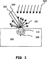
図1は、本発明の実施例に従ってレーザ超音波変位および熱過渡現象を生成および検出するための生成レーザビームおよび検出レーザビームの使用法を示す。レーザビーム102が超音波を生成し、一方照明(検出)レーザビーム104が試験中の複合材料のような、目標106でこの超音波を検出する。目標106に熱過渡現象を誘発するために、赤外線(IR)のような、放射線を向けるために、フラッシュランプ(図示せず)のような、熱源を使ってもよい。熱放射線が目標106の全てを同時に照射してもよい。それで赤外線画像と超音波検査の間に冷却期間があってもよい。この超音波検査に関連するレーザは、目標106と同軸に適用してもよい。生成レーザビーム102は、目標106に熱弾性膨張112を生じ、それが超音波変形または波108を形成する結果となる。変形または超音波108は、目標106を伝播し、検出レーザビーム104を変調、散乱および反射して目標106から離れる方向に向いた位相変調光110を作り、それを集め且つ処理して目標106の内部構造を示す情報を得る。
FIG. 1 illustrates the use of generated and detected laser beams to generate and detect laser ultrasonic displacements and thermal transients in accordance with an embodiment of the present invention. The
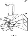
図2は、本発明の実施例に従って超音波試験と赤外線(IR)サーモグラフィの両方を行う検査システムの透視線図を提供する。検査システム200は、サーモグラフィ検査システムに結合した超音波検査システムを含む。この超音波検査システムは、レーザ超音波位置決めシステム202、および走査光学装置206を含むレーザ超音波ヘッド204を含む。これらの作用は、図3を参照して更に詳しく議論する。
FIG. 2 provides a perspective view of an inspection system that performs both ultrasonic testing and infrared (IR) thermography in accordance with an embodiment of the present invention.
このサーモグラフィ検査システムは、IRランプ208とIRカメラ210を含む。これらのIRランプは、複合または目標材料214内に熱過渡現象を誘発する。IRカメラ210は、目標214の赤外線画像を捕捉するように使用可能である。この実施例に示すように、カメラ210の視野は、目標214の像を単一フレームで捕捉するように十分大きくてもよい。その代りにIRカメラ210が複合赤外線画像を創るために使う複数のフレームを捕捉してもよい。或る時系列のイメージを使って目標214の熱的性質に基づいて複合イメージを創ってもよい。これは、例えば、定量的熱肉厚の決定を含んでもよく、その場合、定量的熱肉厚の予期しない変化は、目標214内の切れ目、潜在的切れ目または傷を示す。
The thermographic inspection system includes an
図3は、超音波レーザ試験を行うための基本部品と共にブロック線図を提供する。レーザ超音波検査システム300は、生成レーザ310、検出レーザ320、光学組立体314、収集光学装置326、光プロセッサ328および干渉計330、並びに制御およびデータ処理モジュール332を含む。生成レーザ310は、生成レーザビーム312を生じ、それを光学組立体314が目標316へ向ける。図示するように、光学組立体314は、レーザビーム312を走査または試験計画318に沿って動かすスキャナまたはその他の類似の機構を含む。光学組立体314は、視覚カメラ、深度カメラ、IRカメラ、距離検出器、狭帯域カメラまたは当業者に知られるその他の類似の光センサを含んでもよい。これらの光センサは、検査を行う前に較正が必要かも知れない。この較正は、種々のセンサによって集めた情報をこのシステムが統合する性能を検証する。生成レーザ310は、目標316内に超音波108および熱過渡現象を作る。
FIG. 3 provides a block diagram with the basic components for performing an ultrasonic laser test. Laser
超音波108および熱過渡現象は、複合材料がこの生成レーザビームを吸収するのでこの複合材料の熱弾性膨張112の結果である。複合材料316は、消散または分解せずに生成レーザビーム312を容易に吸収する。高出力生成レーザは、被検査物の表面で材料を消散し、部品を損傷する可能性があるので、信号対雑音比(SNR)問題を克服するためには必ずしも好ましくない。別の実施例では、試験する材料に依っては、検出した信号のSNRを向上するために或る程度の消散が許容されるかも知れない。生成レーザビーム312は、超音波表面変形および適当な熱過渡現象を誘発するために適当なパルス持続時間、出力、および周波数を有する。例えば、横方向励起大気圧(TEA)CO2レーザは、100nsパルス幅に対して波長10.6μmのビームを作ることができる。このレーザの出力は、目標に、例えば、0.25Jのパルスを送出するために十分でなければならず、それは、400Hzのパルス繰返し率で作動する100Wのレーザを要するかも知れない。生成レーザビーム312は、熱としてこの目標表面に吸収され、それによって消散なしに熱弾性膨張を生じる。
パルスモードまたは連続波モードで作動する検出レーザ320は、超音波変位を誘発しない。例えば、Nd:YAGレーザを使うことができる。このレーザの出力は、例えば、100mJ、100μsのパルスを送出するに十分でなければならず、それには1kWのレーザが必要かも知れない。検出レーザ320は、検出レーザビーム322を発生する。検出レーザ320は、検出レーザビーム324から雑音を除去するために濾過機構324を含みまたはそれに光学的に結合してあってもよい。光学組立体314は、検出レーザビーム324を複合材料316の表面へ向け、それが検出レーザビーム324を散乱または反射する。結果として生じた位相変調光を収集光学装置326によって集める。ここに示すように、散乱したおよび/または反射した検出したレーザ光は、光学組立体314を通って戻る。任意の光プロセッサ328および干渉計330がこの位相変調光を処理して複合材料316の表面での超音波変位を表す信号を作る。
この生成レーザビームは、中間IR超音波生成レーザでもよい。その様な生成レーザは、超音波および熱過渡現象生成のためにコンパクトで、高平均出力の中間IRレーザを用意する。図4に示すように、生成レーザ700は、生成レーザヘッド404に結合したファイバであるファイバレーザを中に有するポンプレーザヘッド402を含む。ファイバレーザを使うと、このレーザポンプを生成レーザヘッド404から遠く離して位置付けることを可能にする。このポンプレーザヘッドは、光ファイバ402を介してこの生成レーザヘッド404に結合してもよい。
This generated laser beam may be an intermediate IR ultrasound generating laser. Such a generation laser provides a compact, high average power intermediate IR laser for ultrasonic and thermal transient generation. As shown in FIG. 4, the generation laser 700 includes a
このポンプレーザヘッド402を生成レーザビーム送出ヘッド404から数メートル離して置くことは、コンパクトな中間IR生成レーザヘッドを可能にし、それは全体的ペイロードおよびこの生成レーザビームを送出するためおよびサーマルイメージを取得するために使うロボットまたは位置決めシステムに対する安定性要件を減らす。この生成レーザビーム送出ヘッドおよびIRカメラを含むコンパクトで軽量のモジュールだけをこのロボットシステムの検査ヘッド内に取付ければよい。これは、小さいロボットを使う中間IRレーザ源の展開を可能にする。この様に、可搬式レーザ超音波システムおよびIRサーモグラフィシステムを使う現場複合NDE用に新規な複合検査機会ができる。これらの手法は、“超音波を発生するためのファイバレーザ”という名称の米国特許出願第 号で議論してあり、それを全ての目的でここに援用する。 Placing the pump laser head 402 a few meters away from the production laser beam delivery head 404 allows for a compact intermediate IR production laser head that captures the entire payload and this production laser beam and obtains a thermal image Reduce the stability requirements for the robot or positioning system used to Only a compact and lightweight module including the generated laser beam delivery head and IR camera need be installed in the inspection head of the robot system. This allows deployment of an intermediate IR laser source using a small robot. In this way, there is a new combined inspection opportunity for field combined NDE using portable laser ultrasound systems and IR thermography systems. These approaches are discussed in US Patent Application No. entitled “Fiber Laser for Generating Ultrasound”, which is incorporated herein for all purposes.
図5は、サーモグラフィ検査システムの機能線図を提供する。サーモグラフィ検査システム500は、赤外線画像カメラ(即ち、IRカメラ210)および目標内に熱過渡現象を誘発するためのIRフラッシュランプ208を含む。フラッシュランプ208は、熱放射を所望の位置へ向けるように作用できる反射器を含んでもよい。例えば、これらの反射器は、サーモグラフィに典型的に使うより遠い距離での熱励起を可能にするかも知れない。例えば、これらの反射器は、フラッシュランプをサーモグラフィ検査用により普通の0.3m離すのではなく1.8m離して置くことを可能にする。これは、サーモグラフィ検査システム500とレーザ超音波検査システム300の両方を同じ位置決めシステム上に取付けることを可能にする。これは、カメラ210が典型的離隔距離に関連する視野504に比べて大きい視野502を有することも可能にする。サーモグラフィ検査システム500は、この目標の赤外線画像を捕捉し且つ解析する。これらのイメージを処理して目標316の近表面内部構造についての情報を得る。
FIG. 5 provides a functional diagram of the thermographic inspection system. The
データ処理および制御システム332は、この目標の内部構造についての情報を得るためにレーザ超音波システム部品と赤外線画像部品の作用を調整する。データ処理および制御システム332は、レーザ超音波検査システム300とサーモグラフィ検査システム400の両方の作用を指示する。この処理および制御システムは、この目標の内部構造についての情報を得るために検出した超音波変位および赤外線画像を解析する。次にこの超音波検査の結果およびサーモグラフィ検査の結果を組合わせてこの目標の内部構造のより正確な表現を提供し、その場合、この情報をこの目標のコンピュータモデルに写像してもよい。このデータ処理および制御システムは、或る実施例ではサーモグラフィ検査を最初に行って、次にこの熱過渡現象を治めるためにこのサーモグラフィ検査と超音波検査の間に所定量の時間が経過するように、検査の順序も指示してよい。
The data processing and
データ処理および制御システム332は、単一の処理装置でも複数の処理装置でもよい。その様な処理装置は、マイクロプロセッサ、マイクロコントローラ、デジタル信号プロセッサ、マイクロコンピュータ、CPU、フィールドプログラマブルゲートアレイ、プログラマブル論理デバイス、状態機械、論理回路装置、アナログ回路装置、デジタル回路装置、および/またはメモリに記憶した操作上の指令に基づいて信号(アナログおよび/またはデジタル)を処理する何れかの装置でもよい。このメモリは、単一メモリ装置または複数のメモリ装置でもよい。その様なメモリ装置は、ROM、ランダムアクセスメモリ、揮発性メモリ、不揮発性メモリ、スタティックメモリ、ダイナミックメモリ、フラッシュメモリ、キャッシュメモリ、および/またはデジタル情報を記憶する何れかの装でもよい。このメモリは、後に説明する工程および/または機能の少なくとも幾つかに対応する操作上の指令を記憶し、データ処理および制御システム332が実行する。
The data processing and
図6は、本発明の実施例によるレーザ超音波およびIRイメージングシステム600のブロックまたは機能線図を提供する。レーザ超音波およびIRイメージングシステム600は、生成レーザ602、制御モジュール604、レーザ超音波検出システム606、赤外線画像システム608、処理モジュール610、光学システム612、およびフラッシュランプ616を含む。生成レーザ602は、生成レーザビームを作り、それを光学システム612によって複合材料のような材料であるがそれに限らない材料からなる目標614へ向け、そこに超音波変位を上に議論したように誘発する。レーザ超音波検出システム606は、検出レーザビームを発生し、それを光学システム612によって目標614へ向け、そこで目標614の表面での超音波変位がこの検出レーザビームを位相変調させる。光学システム612は、この目標表面によって散乱した検出レーザビーム光も集める。このレーザ超音波検出システム606は、これらの超音波変位についての情報を含む信号を創り出すために集めた位相変調光を処理する。この信号を処理モジュール610に提供する。
FIG. 6 provides a block or functional diagram of a laser ultrasound and
フラッシュランプ616は、目標614のサーモグラフィ的測定のための熱過渡現象を創成する。IRカメラ608のような赤外線画像システムが目標614内の熱過渡現象の赤外線画像またはフレームを取得する。この視野は、これらの表面または目標614の単一フレームのイメージを可能にしてもよい。その代りに、複数のフレームを取得して複合赤外線画像を作ってもよい。この熱過渡現象中の所定の時間に追加のイメージを取得してもよい。これらの異なるイメージを処理してレーザ・超音波によって検査した全領域のサーモグラフィ検査を行う。
このサーモグラフィ結果は、レーザ超音波結果を補足し、この様にしてより完全でより信頼性のある検査を提供する。過渡現象IRサーモグラフィは、それだけでは高分子マトリックス複合材料のような複合部品の効率的検査ができない。過渡現象IRサーモグラフィは、高分子マトリックスの熱伝導率が低いために複合部品の上端面にしか敏感でない。それで、IRサーモグラフィは、高分子マトリックスまたは複合部品内の深部欠陥を確認、検出且つ確認するためには使えない。 This thermographic result complements the laser ultrasound result and thus provides a more complete and more reliable examination. Transient IR thermography alone cannot efficiently test composite parts such as polymer matrix composites. Transient IR thermography is sensitive only to the top surface of the composite part due to the low thermal conductivity of the polymer matrix. Thus, IR thermography cannot be used to identify, detect and confirm deep defects in a polymer matrix or composite part.
レーザ超音波およびIRイメージングシステム600は、深内部検査システムを提供するレーザ超音波と目標614の近表面検査に取組むための赤外線画像の両方を包含する。これは、レーザ超音波検査が近表面欠陥に敏感でないかも知れないという事実に関連する問題を処理する。これら二つに技術を組合わせることによって、レーザ超音波またはIRサーモグラフィだけを使うときに可能であるよりはより完全な複合部品または材料の非破壊検査が可能である。
Laser ultrasound and
図7は、本発明の実施例に従って平底穴のある高分子板内の熱過渡現象を解析することによって得た赤外線結果を示す。一連の赤外線画像をフラッシュランプの点灯によって始る熱過渡現象中の所定の時間に集めてもよい。目標の表面上の各点が特有の熱過渡現象を経験する。これらの熱過渡現象を使って目標材料に関する熱的性質を決めてもよい。例えば、定量的熱肉厚をこの目標での径時赤外線画像を解析することによって決めてもよい。これは、図7に示すように合成視覚像の形で表してもよい。この処理手法は、赤外線イメージを解析する(更に具体的には、異なるイメージ内の時間の関数としての温度変動を解析する)。IRカメラの各点に対する全てのIRイメージから相対温度変動曲線を形成する。 FIG. 7 shows infrared results obtained by analyzing thermal transients in a polymer plate with flat bottom holes according to an embodiment of the present invention. A series of infrared images may be collected at a predetermined time during a thermal transient that begins with the flash lamp on. Each point on the target surface experiences a unique thermal transient. These thermal transients may be used to determine the thermal properties for the target material. For example, the quantitative thermal wall thickness may be determined by analyzing a radial infrared image at this target. This may be represented in the form of a composite visual image as shown in FIG. This processing technique analyzes infrared images (more specifically, temperature variations as a function of time in different images). A relative temperature variation curve is formed from all IR images for each point of the IR camera.
別の実施例は、近表面欠陥に対して材料を検査するための走査IRサーモグラフィ技術を提供するかも知れない。これは、任意の一時に目標の小さい部分しか加熱しないので、目標の最大熱負荷が限られるようにする。その様なシステムは、熱過渡現象を誘発するために走査レーザを使う。 Another embodiment may provide a scanning IR thermography technique for inspecting materials for near surface defects. This ensures that only a small portion of the target is heated at any one time, so that the target maximum heat load is limited. Such a system uses a scanning laser to induce thermal transients.
目標702内の欠陥がこのグレイスケール画像700ではっきり見える。画像700は、材料702内の種々の点704を含む。この画像は、“合成参照赤外線画像法”という名称の米国特許第6,367,969号に記載してあるようなイメージング法を使って創成してもよく、それを全ての目的のために参考までにここに援用する。IR過渡現象サーモグラフィ解析手法は、目標の厚さを正確に測定し且つこの目標の所望の領域に亘ってその断面厚さを表す可視コード化表示を提供するために使ってもよい。
Defects in
基本的に、好ましくは“前側”IRカメラ観測から得た、急速加熱した目標の表面の温度-時間(T-t)応答解析に於ける変曲点のIR過渡現象サーモグラフィの使用。この変曲点は、このT-tで比較的初期に起り且つ本質的に横方向熱損失機構と関係ない。(その様な考慮は、例えば、金属を扱うときに、金属の熱伝導率が高いために、金属目標の熱的応答がかなり速く、従って、熱的データ測定値を得るために利用できる時間が通常短いので、特に関係があるかも知れない)。この屈曲点を連続するIRカメライメージフレームから所定の期間に亘って取得した熱的データから抽出する。この期間は、評価する目標の厚さの推定に基づく予想特性時間より少なくとも幾らか長いのが好ましい。 Basically, the use of inflection point IR transient thermography in the temperature-time (Tt) response analysis of the rapidly heated target surface, preferably obtained from “front” IR camera observations. This inflection point occurs relatively early at this Tt and is essentially unrelated to the transverse heat loss mechanism. (Such considerations include, for example, when working with metals, the thermal response of the metal target is much faster due to the high thermal conductivity of the metal, and thus the time available to obtain thermal data measurements. It is usually short and may be particularly relevant). This inflection point is extracted from thermal data acquired over a predetermined period from successive IR camera image frames. This period is preferably at least somewhat longer than the expected characteristic time based on an estimate of the target thickness to be evaluated.
熱的参照データを結像した目標の各(x,y)画素位置に対して計算し、次に各画素に対してコントラストを時間の関数として決めるために使う。コンピュータシステムがこのイメージングシステムを制御し、IRカメラを介して取得した表面温度データを記録し且つ解析し、およびこの目標の厚さに正確に対応するカラーまたはグレーパターンに統合したイメージを提供する。この情報をレーザ超音波データと組合わせてこの目標のより詳細な内部画像を作ってもよい。 Thermal reference data is calculated for each (x, y) pixel location of the imaged target and then used to determine the contrast as a function of time for each pixel. A computer system controls the imaging system, records and analyzes the surface temperature data acquired via the IR camera, and provides an image integrated into a color or gray pattern that accurately corresponds to the target thickness. This information may be combined with laser ultrasound data to create a more detailed internal image of this target.
この表面温度データの取得は、この目標の表面の一部を照射し且つ加熱するためにこの生成レーザを点火することに始る。次に熱的イメージフレームを各生成レーザパルスの後の或る期間に亘って記録しおよび記録したイメージを熱過渡現象に関連するもののような、温度-時間(T-t)履歴を創り出すために使う。 Acquisition of the surface temperature data begins with igniting the generated laser to illuminate and heat a portion of the target surface. A thermal image frame is then recorded over a period after each generated laser pulse and the recorded image is created to create a temperature-time (Tt) history, such as that associated with thermal transients. use.
次に各解像要素位置でのこの目標の厚さを決めるために、取得したイメージフレームの各画素に対してこのT-t履歴の熱流解析を行う。通常、目標の固体部を通る過渡熱流の解析は、熱エネルギーの“パルス”がこの目標の第1面を貫通し、反対面から反射しおよびこの第1面へ戻るために要する特性時間を決めることが必要である。この特性時間は、二つの面間の距離に関係するので、それを使って所望の点でのこの目標の二つの面間の厚さを決めることができる。この目標表面の各解像要素に対応する各(x,y)画素位置に対してコントラスト対時間曲線を決める。 Next, in order to determine the target thickness at each resolution element position, heat flow analysis of this Tt history is performed for each pixel of the acquired image frame. Typically, analysis of transient heat flow through a target solid determines the characteristic time required for a “pulse” of thermal energy to penetrate the first surface of the target, reflect from the opposite surface, and return to the first surface. It is necessary. Since this characteristic time is related to the distance between the two faces, it can be used to determine the thickness between the two faces of this target at the desired point. A contrast versus time curve is determined for each (x, y) pixel position corresponding to each resolution element on the target surface.
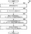
図8は、本発明の実施例に従って目標材料を検査するための方法を記述する論理流れ図を提供する。この方法は、この目標材料のより正確且つ信頼性のある試験を提供するために超音波検査とサーモグラフィ検査を組合わせる。作業800は、工程802に始る。工程802では、サーモグラフィ検査を行ってもよい。このサーモグラフィ検査を行った後に、超音波検査を行ってもよい。先に議論したように、超音波データとサーモグラフィデータの相関を助けるために、この超音波検査システムとサーモグラフィ検査システムが共通の位置決めシステムを共有してもよい。このサーモグラフィ検査と工程804の超音波検査の間に時間間隔があってもよい。これは、この目標材料が熱平衡に戻るかまたはこの熱過渡現象が治るようにする。この時間間隔は、この熱過渡現象が超音波検査の結果に影響するのを防ぐ。工程806で、超音波検査に関連して検出した超音波変位およびサーモグラフィ検査に関連する赤外線画像を解析して超音波検査結果およびサーモグラフィ検査結果を出す。工程808で、これらの結果を組合わせる。
FIG. 8 provides a logic flow diagram describing a method for inspecting a target material in accordance with an embodiment of the present invention. This method combines ultrasonic and thermographic inspection to provide a more accurate and reliable test of the target material.
サーモグラフィは、目標材料の合成イメージまたはその他の表示ができるようにする。これは、赤外線画像を解析することによって到達すする定量的熱的厚さの決定を伴うかも知れない。この定量的熱肉厚の変化は、この定量的熱肉厚に予期しない変化が起る点でのこの目標材料の近表面傷を示すかも知れない。この情報をコントラストディスプレイによって可視化してもよく、そうすればコントラストの急激な変化がこの定量的熱肉厚の切れ目または変化を示す。これらの結果を組合わせると、目標材料のより正確な理解ができる結果となる。サーモグラフィ検査は、表面欠陥のために目標材料を調べるのにより良く適し、一方超音波検査は、深い内部欠陥により良く適する。これらの結果を組合わせて工程810でコンピュータモデルに当てはめてもよい。サーモグラフィ検査システムと超音波検査システムの組合わせは、両検査システムが共通の検査プラットホームを共有できるようにする。更に、サーモグラフィ検査システムの位置決めを較正するためにレーザ超音波位置決めを使ってもよい。これは、より正確な解析およびサーモグラフィと超音波データの相関を可能にする。要約すると、目標材料の内部構造を調べるための検査システムを提供する。この検査システムは、超音波検査システムとサーモグラフィ検査システムを組合わせる。このサーモグラフィ検査システムを超音波検査システムに取付け、レーザ超音波検査と両立する距離で目標材料のサーモグラフィ検査ができるように修正する。この目標材料上で深部赤外線(IR)イメージングを使って定量的情報を得る。このIRイメージングおよびレーザ超音波の結果を組合わせて複雑な形状の複合材の3次元投影法で投影する。このサーモグラフィの結果がレーザ・超音波結果を補足して、特に目標材料が薄い複合部品であるときに、より完全でより信頼性のある、目標材料の内部構造についての情報をもたらす。
Thermography allows a composite image or other display of the target material. This may involve determining the quantitative thermal thickness that is reached by analyzing the infrared image. This quantitative thermal wall thickness change may indicate a near surface flaw of the target material at an unexpected change in the quantitative thermal wall thickness. This information may be visualized by a contrast display so that a rapid change in contrast indicates a break or change in this quantitative thermal wall thickness. Combining these results results in a more accurate understanding of the target material. Thermographic inspection is better suited for examining target materials for surface defects, while ultrasonic inspection is better suited for deep internal defects. These results may be combined and applied to the computer model at
当業者には分るように、ここで使うかも知れないような、“実質的に”または“ほぼ”という用語は、その対応する用語に業界が容認する許容差を与える。その様な業界が容認する許容差は、1パーセント未満から20パーセントに及び且つ部品値、集積回路プロセス変動、温度変動、上下回数、および/または熱雑音に対応するがそれに限らない。当業者は更に分るように、ここで使うかも知れないような、“使用できるように結合した”という用語は、直接結合および別の部品、要素、回路、またはモジュールを介する間接結合を含み、その場合、間接結合に関して、介在する部品、要素、回路、またはモジュールは信号の情報を変更しないが、その電流レベル、電圧レベル、および/または出力レベルを調整してもよい。当業者はやはり分るように、推定結合は、“使用できるように結合した”と同様に、二つの要素間の直接および間接結合を含む。当業者は更に分るように、ここで使うかも知れないような、“都合よく比較する”という用語は、二つ以上の要素、項目、信号等の間の比較が所望の関係をもたらすことを示す。例えば、所望の関係は、信号1の大きさが信号2より大きいことであれば、都合のよい比較は、信号1の大きさが信号2のそれより大きいとき、または信号2の大きさが信号1のそれより小さいときに行ってもよい。 As will be appreciated by those skilled in the art, the term “substantially” or “approximately”, as may be used herein, confers an industry-acceptable tolerance on that corresponding term. The tolerances accepted by such industries range from less than 1 percent to 20 percent and correspond to, but are not limited to, component values, integrated circuit process variations, temperature variations, up / down frequency, and / or thermal noise. As those skilled in the art will further appreciate, the term “operably coupled”, as may be used herein, includes direct coupling and indirect coupling through another part, element, circuit, or module; In that case, with respect to indirect coupling, intervening parts, elements, circuits or modules do not change the signal information, but may adjust their current level, voltage level and / or output level. As will also be appreciated by those skilled in the art, putative coupling includes direct and indirect coupling between two elements, as well as “combined to use”. As those skilled in the art will further appreciate, the term “conveniently compare”, as may be used herein, means that a comparison between two or more elements, items, signals, etc. provides the desired relationship. Show. For example, if the desired relationship is that the magnitude of signal 1 is greater than signal 2, then a convenient comparison is that when the magnitude of signal 1 is greater than that of signal 2, or the magnitude of signal 2 is signal It may be done when it is less than one.
本発明を詳細に説明したが、これに種々の変更、置換および改造を添付の請求項に定義するこの発明の精神および範囲から逸脱することなく行えることを理解すべきである。 Although the invention has been described in detail, it should be understood that various changes, substitutions and modifications can be made thereto without departing from the spirit and scope of the invention as defined in the appended claims.
Claims (17)
前記目標材料に超音波音響振動を誘発するための生成レーザと、前記振動を検出するための検出レーザとを有するレーザ超音波検査システムを使って前記目標材料のレーザ超音波検査を行う工程、
サーモグラフィ検査システムを使って前記目標材料のサーモグラフィ検査を行う工程、
前記超音波検査試験システムおよび前記サーモグラフィ検査システムを、レーザ超音波検査システムには典型的であるがサーモグラフィに典型的に使うより大きい前記目標材料からの離隔距離に提供する工程、および
前記目標材料の内部構造を決めるためにレーザ超音波検査結果とサーモグラフィ検査結果の両方を解析する工程
を含む方法。A method for inspecting a target material, comprising:
Step of performing a generation laser, a laser ultrasound inspection of the target material with a laser ultrasonic inspection system and a detection laser for detecting the vibration to induce ultrasonic acoustic vibration to the target material,
Step for thermographic examination of the target material using the thermographic inspection system,
Providing the ultrasonic inspection test system and the thermographic inspection system to a larger separation from the target material that is typical for laser ultrasonic inspection systems but typically used for thermography; and
Method comprising the step of analyzing both laser ultrasound inspection results and thermography inspection result to determine the internal structure of the target material.
前記目標材料に熱過渡現象を誘発するために前記目標材料を照射する工程、
前記目標材料の経時サーマルイメージを取得する工程、および
前記目標材料についての情報を得るために前記目標材料のサーマルイメージを解析する工程を含む方法。The method of claim 1, wherein the thermographic inspection comprises:
Irradiating the target material to induce thermal transients on the target material;
Obtaining a thermal image of the target material over time, and analyzing the thermal image of the target material to obtain information about the target material .
前記目標材料が複合材料を含むとき、この複合材料の近表面内部構造についての情報が得られるように、前記サーモグラフィ検査結果からの目標材料のサーマルイメージを解析する工程をさらに含む方法。The method according to claim 1, wherein when the target material includes a composite material, the ultrasonic displacement detected by the ultrasonic inspection result is analyzed so that information about a deep internal structure of the composite material can be obtained. method steps, and when the target material comprises a composite material, so that information about the near surface internal structure of the composite material is obtained, further comprising the step of analyzing the thermal image of the target material from the thermography test result .
検出レーザビームを発生する工程、
前記検出レーザビームを前記目標材料の表面へ向ける工程、
前記目標材料の表面で前記検出レーザビームを散乱して超音波表面変位によって位相変調した光を作る工程、
前記位相変調した光を集める工程、
前記位相変調した光を処理して前記表面での超音波変位を表すデータを得る工程、および
前記目標材料を解析するためにデータを集める工程
を含む方法。The method of claim 1, wherein the ultrasonic inspection comprises:
Generating a detection laser beam;
Directing the detected laser beam to a surface of the target material;
Process of making a light phase modulation by the scattering to the ultrasonic surface displacements of the detection laser beam at the surface of said target material,
Step of collecting the light the phase modulation,
Which comprises the step of collecting data in order to analyze the phase step modulated by processing the light obtain data representative of the ultrasonic displacements at the surface, and the target material.
前記目標内の超音波変位を創成し且つ検出することによって前記目標の内部構造を検査するために使用できるレーザ超音波検査システム、
前記レーザ超音波検査システムと同じ位置決めシステム上に取付けられ、前記目標の内部構造を検査し且つ前記目標のサーマルイメージを得るために使用できるサーモグラフィ検査システムであって、前記位置決めシステムは、レーザ超音波検査システムには典型的であるがサーモグラフィに典型的に使うより大きい前記目標材料からの離隔距離に配置されているサーモグラフィ検査システム、
処理および制御システムであって、
前記目標の内部構造についてのサーモグラフィ検査結果を得るために前記目標のサーマルイメージを解析し、
前記目標の内部構造についての超音波検査結果を得るために前記目標で検出した超音波変位を解析し、また
前記目標の内部構造についての情報を得るために前記目標材料の前記超音波検査結果と前記サーモグラフィ検査結果を組合わせる
ために使用できる処理および制御システム
を含む検査システム。An inspection system that can be used to inspect the target internal structure,
The laser ultrasonic inspection system that can be used to examine the internal structure of the target by creating and and detecting the ultrasonic displacements in the target,
Wherein mounted on the same positioning system as the laser ultrasonic inspection system, a thermographic inspection system that can be used to obtain a thermal image of the examined and the target of the internal structure of the target, the positioning system, laser ultrasound A thermographic inspection system, which is typical for inspection systems, but is located at a greater distance from the target material than is typically used for thermography ;
A processing and control system,
Analyzing the thermal image of the target in order to obtain a thermographic inspection results of the internal structure of the target,
Analyzing the ultrasound displacements detected by the target in order to obtain the ultrasonic inspection results for the internal structure of the target, also
Inspection system includes a processing and control system can be used to combine the said thermographic inspection result ultrasonography result of the target material in order to obtain information about the internal structure of the target.
前記目標での前記超音波表面変位を照射するために使用できる検出レーザビームを発生するために使用できる検出レーザ、
前記目標表面によって散乱した検出レーザビームから超音波表面変位によって位相変調した光を収集するための収集光学装置、
位相変調した光を処理し且つ少なくとも一つの出力信号を発生するための干渉計、および
前記目標での超音波表面変位を表すデータを得るために少なくとも一つの出力信号を処理するための光処理ユニット
を含むシステム。The inspection system according to claim 9, wherein the laser ultrasonic inspection system comprises:
A detection laser that can be used to generate a detection laser beam that can be used to illuminate the ultrasonic surface displacement at the target;
A collection optical device for collecting light phase-modulated by ultrasonic surface displacement from a detection laser beam scattered by the target surface;
An interferometer for processing the phase modulated light and generating at least one output signal; and
System including an optical processing unit for processing at least one output signal to obtain data representative of the ultrasonic surface displacements at the target.
前記複合材料の深内部構造についての情報を得るために検出した超音波変位を解析し、Analyzing the ultrasonic displacement detected to obtain information about the deep internal structure of the composite material;
複合材料の近表面内部構造についての情報を得るために前記目標でのサーマルイメージを解析し、またAnalyzing the thermal image at the target to obtain information about the near-surface internal structure of the composite material, and
複合材料の深内部構造とこの複合材料の近表面内部構造についての情報を相関付けるCorrelate information about the deep internal structure of the composite and the near-surface internal structure of the composite
ようになっているシステム。The system that has become.
試験中の複合材料に超音波変位および熱過渡現象を誘発するために使用できるパルス式レーザビームを発生するために使用できる生成レーザ、
前記複合材料での前記超音波表面変位を検出するために使用できるレーザ超音波検出システム、
前記複合材料での前記熱過渡現象を検出するために使用できるサーマルイメージングシステムであって、レーザ超音波検査システムには典型的であるがサーモグラフィに典型的に使うより大きいテスト中の前記複合材料からの離隔距離に、前記レーザ超音波検出システムとともに取付けられるサーマルイメージングシステム、
サーマルイメージフレーム取得を前記生成レーザビームのパルス繰返し率に整合させるために使用できる制御モジュール、および
前記複合材料の内部構造についての情報を得るために、前記複合材料で検出した超音波変位と前記複合材料のサーマルイメージの両方を解析するために使用できるプロセッサ
を含むシステム。 A large area combined inspection system,
A generated laser that can be used to generate a pulsed laser beam that can be used to induce ultrasonic displacement and thermal transients in the composite under test ,
A laser ultrasonic detection system that can be used to detect the ultrasonic surface displacement in the composite material;
A thermal imaging system that can be used to detect the thermal transients in the composite material from the composite material under test that is typical for laser ultrasonography systems but typically used for thermography. A thermal imaging system mounted with the laser ultrasound detection system at a separation distance of
A control module that can be used to match the thermal image frame acquisition to the pulse repetition rate of the generated laser beam; and
A processor that can be used to analyze both the ultrasonic displacement detected in the composite material and the thermal image of the composite material to obtain information about the internal structure of the composite material
Including system.
Applications Claiming Priority (3)
| Application Number | Priority Date | Filing Date | Title |
|---|---|---|---|
| US11/567,405 US7605924B2 (en) | 2006-12-06 | 2006-12-06 | Laser-ultrasound inspection using infrared thermography |
| US11/567,405 | 2006-12-06 | ||
| PCT/US2007/025229 WO2009035445A1 (en) | 2006-12-06 | 2007-12-06 | Improved laser-ultrasound inspection using infrared thermopgraphy |
Publications (3)
| Publication Number | Publication Date |
|---|---|
| JP2010512509A JP2010512509A (en) | 2010-04-22 |
| JP2010512509A5 JP2010512509A5 (en) | 2012-04-26 |
| JP5197624B2 true JP5197624B2 (en) | 2013-05-15 |
Family
ID=39497600
Family Applications (1)
| Application Number | Title | Priority Date | Filing Date |
|---|---|---|---|
| JP2009540331A Expired - Fee Related JP5197624B2 (en) | 2006-12-06 | 2007-12-06 | Improved laser and ultrasonic inspection using infrared thermography |
Country Status (10)
| Country | Link |
|---|---|
| US (1) | US7605924B2 (en) |
| EP (1) | EP2097742A1 (en) |
| JP (1) | JP5197624B2 (en) |
| KR (1) | KR101385402B1 (en) |
| CN (1) | CN101606058B (en) |
| AU (1) | AU2007358774B2 (en) |
| BR (1) | BRPI0719913A2 (en) |
| CA (1) | CA2671741C (en) |
| IL (1) | IL199220A (en) |
| WO (1) | WO2009035445A1 (en) |
Families Citing this family (51)
| Publication number | Priority date | Publication date | Assignee | Title |
|---|---|---|---|---|
| DE102006044443A1 (en) * | 2006-09-21 | 2008-04-03 | Robert Bosch Gmbh | Automatic detection of coating defects |
| US7966883B2 (en) * | 2006-12-06 | 2011-06-28 | Lockheed Martin Corporation | Non-destructive inspection using laser-ultrasound and infrared thermography |
| US8086042B2 (en) * | 2006-12-29 | 2011-12-27 | Johns Manville | Weatherization imaging systems and methods |
| US8010315B2 (en) * | 2007-11-27 | 2011-08-30 | General Electric Company | Multi-modality inspection method with data validation and data fusion |
| US7840367B2 (en) * | 2007-11-28 | 2010-11-23 | General Electric Company | Multi-modality inspection system |
| CA2672378A1 (en) * | 2007-12-06 | 2009-06-11 | Lockheed Martin Corporation | Non-destructive inspection using laser-ultrasound and infrared thermography |
| US20090287450A1 (en) * | 2008-05-16 | 2009-11-19 | Lockheed Martin Corporation | Vision system for scan planning of ultrasonic inspection |
| US8243280B2 (en) * | 2008-05-20 | 2012-08-14 | Iphoton Solutions, Llc | Laser ultrasonic measurement system with movable beam delivery |
| WO2011051874A1 (en) * | 2009-10-28 | 2011-05-05 | Csir | Integrated sensing device for assessing integrity of a rock mass and corresponding method |
| US20110193558A1 (en) * | 2010-02-02 | 2011-08-11 | Morpho Detection, Inc. | Passenger scanning systems for detecting contraband |
| CN101858890B (en) * | 2010-05-14 | 2011-10-26 | 东南大学 | Detecting system of superficial defects of small-size materials |
| CN101852774B (en) * | 2010-05-14 | 2012-10-24 | 西安金波检测仪器有限责任公司 | Flaw detection system and flaw detection method |
| US8705028B2 (en) | 2010-08-06 | 2014-04-22 | Par Systems, Inc. | Containerized systems |
| CN102221339B (en) * | 2011-06-09 | 2012-09-05 | 首都师范大学 | Method for measuring thickness by pulse infrared thermal wave technology |
| FR2981157B1 (en) * | 2011-10-05 | 2013-10-25 | Aircelle Sa | METHOD FOR NON-DESTRUCTIVE CONTROL OF ORGANIC MATRIX COMPOSITE MATERIAL |
| DE102011086267A1 (en) * | 2011-11-14 | 2013-05-16 | Siemens Aktiengesellschaft | System and method for controlling a thermographic measuring process |
| US20160027172A1 (en) | 2012-04-04 | 2016-01-28 | James G. Spahn | Method of Monitoring the Status of a Wound |
| CN102600002A (en) * | 2012-04-13 | 2012-07-25 | 上海桂莘实业有限公司 | Laser-induced photothermic therapy, monitoring and thermal imaging system |
| KR101369212B1 (en) * | 2012-08-01 | 2014-03-27 | 한국과학기술원 | Laser ultrasonic imaging of a rotating blade |
| WO2014073944A1 (en) * | 2012-11-09 | 2014-05-15 | Universidad Nacional Autónoma de México | A system and process for dynamic non-invasion inspection of the interior of soft biological matter |
| CN103033597A (en) * | 2012-12-07 | 2013-04-10 | 上海宝冶工程技术有限公司 | Online detection method for pipelines of blast furnace |
| US20140210992A1 (en) * | 2013-01-31 | 2014-07-31 | United Technologies Corporation | Infrared thermography with laser |
| JP5973965B2 (en) * | 2013-06-28 | 2016-08-23 | 株式会社豊田中央研究所 | Bondability evaluation apparatus and bondability evaluation method |
| DE102013219311A1 (en) * | 2013-09-25 | 2015-03-26 | Siemens Aktiengesellschaft | Method for induction thermography |
| WO2015074626A1 (en) * | 2013-11-25 | 2015-05-28 | 王浩 | Thermal image analysis apparatus, configuration apparatus, thermal image analysis method, and configuration method |
| US9347899B2 (en) | 2013-12-06 | 2016-05-24 | Rolls-Royce Corporation | Thermographic inspection techniques |
| US9832396B2 (en) * | 2013-12-18 | 2017-11-28 | United Technologies Corporation | Composite image processing for LWIR images using geometric features |
| CN103983513B (en) * | 2014-05-22 | 2016-03-02 | 中国矿业大学 | A kind of device and method adopting infrared radiation to observe coal petrography cranny development process |
| JP6372818B2 (en) * | 2014-06-13 | 2018-08-15 | 公立大学法人 滋賀県立大学 | Infrared defect detection system using ultrasonic waves |
| DE102014218136B4 (en) * | 2014-09-10 | 2019-07-18 | Fraunhofer-Gesellschaft zur Förderung der angewandten Forschung e.V. | Thermographic examination device and method for the non-destructive examination of a near-surface structure on a test object |
| US10460251B2 (en) * | 2015-06-19 | 2019-10-29 | Preferred Networks Inc. | Cross-domain time series data conversion apparatus, methods, and systems |
| US9995670B2 (en) * | 2015-12-09 | 2018-06-12 | The Boeing Company | Method of controlling a laser bond inspection system |
| CN107356956B (en) * | 2016-05-09 | 2019-03-12 | 中国石油化工股份有限公司 | A kind of laser-ultrasound experimental system of relief surface physical model |
| CN106198731A (en) * | 2016-07-19 | 2016-12-07 | 中国人民解放军装甲兵工程学院 | Matrix fatigue crack recognition methods under sprayed coating |
| US10728426B1 (en) | 2016-08-17 | 2020-07-28 | United States Of America As Represented By The Administrator Of The National Aeronautics And Space Administration | Contrast based imaging and analysis computer-implemented method to analyze pulse thermography data for nondestructive evaluation |
| US10046918B2 (en) * | 2016-10-28 | 2018-08-14 | Embraer S.A. | Continuous belt conveyor monitoring systems and methods |
| WO2018215053A1 (en) * | 2017-05-23 | 2018-11-29 | Brainlab Ag | Determining the relative position between a point cloud generating camera and another camera |
| EP3710813B1 (en) * | 2017-11-13 | 2023-09-20 | Illumina, Inc. | System and method for large sample analysis of thin film |
| US10677715B2 (en) * | 2017-11-22 | 2020-06-09 | The Boeing Company | Thermography inspection for near-surface inconsistencies of composite structures |
| CN108333219A (en) * | 2018-03-19 | 2018-07-27 | 长沙理工大学 | A kind of online lossless detection method for band large-scale metal component laser gain material manufacturing process |
| US10788462B2 (en) * | 2018-06-29 | 2020-09-29 | The Boeing Company | Dual function non-destructive inspection apparatus and method |
| CN109459492A (en) * | 2018-10-17 | 2019-03-12 | 山东省科学院海洋仪器仪表研究所 | The optoacoustic photo-thermal complex detection system and method for invar steel sheet weld crack defect |
| US11644443B2 (en) * | 2018-12-17 | 2023-05-09 | The Boeing Company | Laser ultrasound imaging |
| US11435305B2 (en) | 2018-12-19 | 2022-09-06 | General Electric Company | Thermographic inspection system mounted on motorized apparatus and methods of using same |
| US11474058B2 (en) * | 2019-01-10 | 2022-10-18 | General Electric Company | Systems and methods for detecting water in a fan case |
| JP7308577B2 (en) | 2020-06-01 | 2023-07-14 | ヤマハロボティクスホールディングス株式会社 | Acoustic defect detection device and defect detection method |
| TWI801893B (en) * | 2020-09-11 | 2023-05-11 | 日商鎧俠股份有限公司 | Defect inspection device and defect inspection method |
| KR102285477B1 (en) | 2020-10-26 | 2021-08-03 | 이현철 | Apparatus and Method for Noncontact and Non Destructive Test of Defects Inside Metal using Photoacoustic Imaging for After Induction Hardening |
| CN112485329B (en) * | 2020-11-27 | 2024-01-26 | 重庆商勤科技有限公司 | Method, device and system for detecting sewage outlet based on combination of thermal imaging and ultrasound |
| US11639914B2 (en) * | 2020-12-16 | 2023-05-02 | The Boeing Company | Non-destructive test systems with infrared thermography assemblies and ultrasonic test assemblies, and associated methods |
| CN116250809B (en) * | 2023-05-10 | 2023-07-21 | 广东工业大学 | Ultrasonic nerve regulation target area positioning device and method |
Family Cites Families (20)
| Publication number | Priority date | Publication date | Assignee | Title |
|---|---|---|---|---|
| JPS6478138A (en) * | 1987-09-21 | 1989-03-23 | Jgc Corp | Inspecting device for soundness of drum packed with radioactive waste |
| US4896278A (en) * | 1988-07-11 | 1990-01-23 | Northrop Corporation | Automated defect recognition system |
| US5638396A (en) * | 1994-09-19 | 1997-06-10 | Textron Systems Corporation | Laser ultrasonics-based material analysis system and method |
| JPH08285820A (en) * | 1995-04-17 | 1996-11-01 | Nippon Steel Corp | Laser-ultrasonic inspection apparatus |
| US6122060A (en) * | 1998-06-30 | 2000-09-19 | Lockheed Martin Corporation | Method and apparatus for detecting ultrasonic surface displacements using post-collection optical amplification |
| US20040154402A1 (en) * | 1998-06-30 | 2004-08-12 | Lockheed Martin Corporation | Remote laser beam delivery system and method for use with a robotic positioning system for ultrasonic testing purposes |
| US6367969B1 (en) | 1999-07-21 | 2002-04-09 | General Electric Company | Synthetic reference thermal imaging method |
| GB9921970D0 (en) * | 1999-09-16 | 1999-11-17 | Univ London | An optical interferometer sensor array |
| JP2003513733A (en) | 1999-11-17 | 2003-04-15 | グラクソ グループ リミテッド | Infrared thermography |
| JP4467862B2 (en) * | 1999-12-02 | 2010-05-26 | サーマル・ウェーブ・イメージング、インク | System and method for detecting near-surface defects thermographically without reference using compressed image data |
| IL153807A0 (en) * | 2000-07-14 | 2003-07-31 | Lockheed Corp | A system and method of determining porosity in composite materials using ultrasound |
| US6696692B1 (en) * | 2000-11-06 | 2004-02-24 | Hrl Laboratories, Llc | Process control methods for use with e-beam fabrication technology |
| US6712502B2 (en) * | 2002-04-10 | 2004-03-30 | The United States Of America As Represented By The Administrator Of The National Aeronautics And Space Administration | Synchronized electronic shutter system and method for thermal nondestructive evaluation |
| US6998616B2 (en) * | 2002-08-28 | 2006-02-14 | Wayne State University | System and method for acoustic chaos and sonic infrared imaging |
| US7060971B2 (en) * | 2002-09-13 | 2006-06-13 | Siemens Westinghouser Power Corporation | Reference standard systems for thermosonic flaw detection |
| US7084402B2 (en) * | 2003-11-25 | 2006-08-01 | The Boeing Company | Liquid coupled defect detection systems and methods |
| WO2005062941A2 (en) * | 2003-12-22 | 2005-07-14 | Bossa Nova Technologies, Llc | Multi-channel laser interferometric method and apparatus for detection of ultrasonic motion from a surface |
| JP2006170684A (en) * | 2004-12-14 | 2006-06-29 | Toyota Motor Corp | Method and device for inspecting press failure |
| CN100456016C (en) * | 2006-05-30 | 2009-01-28 | 华南师范大学 | Multi-channel electronic parallel scanning photoacoustic real-time tomo graphic-imaging method and apparatus thereof |
| US7612894B2 (en) * | 2006-07-18 | 2009-11-03 | Lockheed Martin Corporation | Fiber laser for ultrasonic testing |
-
2006
- 2006-12-06 US US11/567,405 patent/US7605924B2/en not_active Expired - Fee Related
-
2007
- 2007-12-06 CN CN2007800509927A patent/CN101606058B/en not_active Expired - Fee Related
- 2007-12-06 CA CA2671741A patent/CA2671741C/en not_active Expired - Fee Related
- 2007-12-06 WO PCT/US2007/025229 patent/WO2009035445A1/en active Application Filing
- 2007-12-06 KR KR1020097013390A patent/KR101385402B1/en not_active IP Right Cessation
- 2007-12-06 BR BRPI0719913-9A2A patent/BRPI0719913A2/en not_active Application Discontinuation
- 2007-12-06 EP EP07875202A patent/EP2097742A1/en not_active Withdrawn
- 2007-12-06 JP JP2009540331A patent/JP5197624B2/en not_active Expired - Fee Related
- 2007-12-06 AU AU2007358774A patent/AU2007358774B2/en not_active Ceased
-
2009
- 2009-06-07 IL IL199220A patent/IL199220A/en not_active IP Right Cessation
Also Published As
| Publication number | Publication date |
|---|---|
| IL199220A (en) | 2013-03-24 |
| JP2010512509A (en) | 2010-04-22 |
| AU2007358774A1 (en) | 2009-03-19 |
| KR20090096474A (en) | 2009-09-10 |
| CA2671741A1 (en) | 2009-03-19 |
| US7605924B2 (en) | 2009-10-20 |
| EP2097742A1 (en) | 2009-09-09 |
| CN101606058A (en) | 2009-12-16 |
| KR101385402B1 (en) | 2014-04-14 |
| US20080137105A1 (en) | 2008-06-12 |
| WO2009035445A1 (en) | 2009-03-19 |
| BRPI0719913A2 (en) | 2014-03-04 |
| AU2007358774B2 (en) | 2013-04-04 |
| CN101606058B (en) | 2013-11-20 |
| CA2671741C (en) | 2016-03-22 |
Similar Documents
| Publication | Publication Date | Title |
|---|---|---|
| JP5197624B2 (en) | Improved laser and ultrasonic inspection using infrared thermography | |
| JP5307155B2 (en) | Nondestructive inspection using laser ultrasound and infrared thermography | |
| US7966883B2 (en) | Non-destructive inspection using laser-ultrasound and infrared thermography | |
| US7369250B2 (en) | System and method to inspect components having non-parallel surfaces | |
| US7681453B2 (en) | System and method to calibrate multiple sensors | |
| US6874932B2 (en) | Methods for determining the depth of defects | |
| JP6301951B2 (en) | Sample inspection method and system using thermography | |
| JP2010512509A5 (en) | ||
| JP2004515748A (en) | System and method for detecting porosity of composites using ultrasound | |
| JP2003505692A (en) | Imaging method based on synthetic thermal criteria | |
| US20080144049A1 (en) | Method and apparatus for thermographic nondestructive evaluation of an object | |
| JP2003505683A (en) | Thermal resonance imaging method | |
| US11692810B2 (en) | Photoacoustic excitation sensing enhanced by cross-correlated unfocused speckle images | |
| WO2020204817A1 (en) | Non-contact non-destructive testing method and system | |
| KR101351231B1 (en) | Method and Apparatus For Spectroscopic Characterization Of Samples Using A Laser-Ultrasound System | |
| RU2664933C1 (en) | Method for determining surface macrorelief and interior inclusions of an object and device for its implementation | |
| Deason et al. | Ultrasonic imaging of subsurface objects using photorefractive dynamic holography |
Legal Events
| Date | Code | Title | Description |
|---|---|---|---|
| A621 | Written request for application examination |
Free format text: JAPANESE INTERMEDIATE CODE: A621 Effective date: 20101109 |
|
| A521 | Request for written amendment filed |
Free format text: JAPANESE INTERMEDIATE CODE: A523 Effective date: 20120307 |
|
| A977 | Report on retrieval |
Free format text: JAPANESE INTERMEDIATE CODE: A971007 Effective date: 20120523 |
|
| A131 | Notification of reasons for refusal |
Free format text: JAPANESE INTERMEDIATE CODE: A131 Effective date: 20120525 |
|
| TRDD | Decision of grant or rejection written | ||
| A01 | Written decision to grant a patent or to grant a registration (utility model) |
Free format text: JAPANESE INTERMEDIATE CODE: A01 Effective date: 20130129 |
|
| A61 | First payment of annual fees (during grant procedure) |
Free format text: JAPANESE INTERMEDIATE CODE: A61 Effective date: 20130205 |
|
| FPAY | Renewal fee payment (event date is renewal date of database) |
Free format text: PAYMENT UNTIL: 20160215 Year of fee payment: 3 |
|
| R150 | Certificate of patent or registration of utility model |
Free format text: JAPANESE INTERMEDIATE CODE: R150 |
|
| R250 | Receipt of annual fees |
Free format text: JAPANESE INTERMEDIATE CODE: R250 |
|
| R250 | Receipt of annual fees |
Free format text: JAPANESE INTERMEDIATE CODE: R250 |
|
| LAPS | Cancellation because of no payment of annual fees |