JP5196977B2 - Image heating device - Google Patents
Image heating device Download PDFInfo
- Publication number
- JP5196977B2 JP5196977B2 JP2007313572A JP2007313572A JP5196977B2 JP 5196977 B2 JP5196977 B2 JP 5196977B2 JP 2007313572 A JP2007313572 A JP 2007313572A JP 2007313572 A JP2007313572 A JP 2007313572A JP 5196977 B2 JP5196977 B2 JP 5196977B2
- Authority
- JP
- Japan
- Prior art keywords
- temperature
- image
- heating
- image heating
- coil
- Prior art date
- Legal status (The legal status is an assumption and is not a legal conclusion. Google has not performed a legal analysis and makes no representation as to the accuracy of the status listed.)
- Expired - Fee Related
Links
Images


Description
本発明は、電磁誘導方式の像加熱装置、および電磁誘導方式の像加熱装置を備える複写機・プリンタ・ファクシミリ等の画像形成装置に関する。 The present invention relates to an electromagnetic induction type image heating apparatus and an image forming apparatus such as a copying machine, a printer, and a facsimile including the electromagnetic induction type image heating apparatus.
電子写真方式・静電記録方式等の画像形成装置は、シート状の記録材(記録紙・転写材など)上に形成されたトナー画像を記録材上に定着する或いは加熱する像加熱装置を備える。 2. Description of the Related Art Image forming apparatuses such as electrophotographic systems and electrostatic recording systems include an image heating apparatus that fixes or heats a toner image formed on a sheet-like recording material (recording paper, transfer material, etc.) on the recording material. .
この像加熱装置は、像加熱ローラ(定着ローラ)もしくはエンドレスの加熱ベルトである像加熱部材と、像加熱部材を加圧して、記録材を挟持搬送するニップ部を形成する加圧部材と、を有する。 The image heating apparatus includes an image heating roller (fixing roller) or an endless heating belt, and a pressure member that pressurizes the image heating member to form a nip portion that sandwiches and conveys the recording material. Have.
像加熱部材(以下、像加熱ローラと記す)は、発熱体によって内部または外部より、直接もしくは間接的に加熱されて、表面温度が所定の像加熱温度に維持される。発熱体は、例えばハロゲンヒータや抵抗発熱体等が挙げられる。 An image heating member (hereinafter referred to as an image heating roller) is heated directly or indirectly by a heating element from the inside or outside to maintain the surface temperature at a predetermined image heating temperature. Examples of the heating element include a halogen heater and a resistance heating element.
未定着のトナー画像が形成された記録材は、ニップ部で加熱されると共に加圧されて、未定着のトナー画像が記録材面に固着画像として定着される。 The recording material on which the unfixed toner image is formed is heated and pressurized at the nip portion, and the unfixed toner image is fixed on the recording material surface as a fixed image.
近年は、画像形成装置の省エネルギー化と、ウォームアップ時間の短縮といったユーザーの操作性向上の両立を図ることが重視されている。このことから像加熱ローラが直接発熱して発熱効率の高い誘導加熱方式を用いた像加熱装置(以下、誘導加熱装置と記す)が提案されている(特許文献1)。 In recent years, emphasis has been placed on achieving both energy saving of the image forming apparatus and improvement of user operability such as shortening the warm-up time. For this reason, an image heating apparatus (hereinafter referred to as induction heating apparatus) using an induction heating method in which an image heating roller directly generates heat and has high heat generation efficiency has been proposed (Patent Document 1).
この誘導加熱装置は、コイルが発生する磁束の作用によって、金属導体からなる中空の像加熱ローラに誘導電流(渦電流)を発生させ、加熱ローラ自体の表皮抵抗によって加熱ローラそのものがジュール発熱する。そのため、この誘導像加熱装置によれば、像加熱ローラ自身が発熱するためウォームアップ時間の短縮が可能となる。 In this induction heating device, an induction current (eddy current) is generated in a hollow image heating roller made of a metal conductor by the action of magnetic flux generated by a coil, and the heating roller itself generates Joule heat by the skin resistance of the heating roller itself. For this reason, according to this induction image heating apparatus, the image heating roller itself generates heat, so that the warm-up time can be shortened.
また、このような誘導加熱装置においては、印加する高周波電流の周波数、加熱ローラの透磁率および固有抵抗値とから決定される表皮抵抗に比例した電力が発熱する。したがって、印加する高周波電流の周波数を制御することによって、加熱ローラの発熱量を常に最適化することができ、装置の省エネルギー化を達成することが可能となる。 Further, in such an induction heating device, power proportional to the skin resistance determined from the frequency of the applied high frequency current, the magnetic permeability of the heating roller, and the specific resistance value is generated. Therefore, by controlling the frequency of the high-frequency current to be applied, the amount of heat generated by the heating roller can always be optimized, and energy saving of the apparatus can be achieved.
一方で、このような誘導加熱装置にあっては、磁束により発熱する表皮深さがコイルに通電される周波数、像加熱ローラの固有抵抗値によって決められる。そのため、加熱ローラの厚みが表皮深さよりも熱い場合には、発熱量は変わらないため、加熱ローラの厚さが大きくなるほど、かえって発熱効率が低下してしまい、ウォームアップ時間短縮の効果を得ることが困難となる。 On the other hand, in such an induction heating apparatus, the skin depth generated by the magnetic flux is determined by the frequency at which the coil is energized and the specific resistance value of the image heating roller. Therefore, when the thickness of the heating roller is hotter than the skin depth, the amount of heat generated does not change, so the larger the thickness of the heating roller, the lower the heat generation efficiency, and the effect of shortening the warm-up time is obtained. It becomes difficult.
逆に加熱ローラの厚さが表皮深さよりも薄いと、磁束が加熱ローラを突き抜けてしまい、発熱量が少なくなるだけでなく、加熱ローラ周辺の金属部材を加熱してしまう。したがって、加熱ローラの厚さはおおよそ50〜2000μm程度が望ましい。 On the other hand, if the thickness of the heating roller is smaller than the skin depth, the magnetic flux penetrates the heating roller, which not only reduces the amount of heat generation but also heats the metal members around the heating roller. Therefore, the thickness of the heating roller is desirably about 50 to 2000 μm.
このような誘導加熱装置においても、従来の像加熱装置と同様に小サイズの記録材を連続通紙すると、記録材が通過しない非通紙部領域の昇温(非通紙部昇温)が発生する。 In such an induction heating apparatus, similarly to the conventional image heating apparatus, when a small-sized recording material is continuously passed, the temperature rise in the non-sheet passing portion region where the recording material does not pass (non-sheet passing portion temperature rise) is increased. Occur.
この非通紙部昇温対策として、特許文献2に開示されるように、像加熱ローラに、キュリー温度が所定温度に調整された整磁合金を用いた誘導加熱装置が提案されている。一般に磁性材料は、加熱されて材料固有のキュリー温度を越えると自発磁化が消失する。そのため、磁性材料内に通過する磁束密度が減少し、それに伴って磁性材料中に誘導される渦電流が減少することで、磁性材料の発熱量が減少する。そのため、上述の非通紙部昇温を改善することが可能となる。
As a countermeasure against the temperature rise of the non-sheet passing portion, as disclosed in
加熱装置が低温環境で使用される場合、記録材やトナーの温度は低温環境下にあるため低くなっており、定着するために必要なエネルギーが通常環境に比べて増加する。従って、像加熱条件が通常環境と同じ条件では、低温環境では定着が不十分となりやすい。この課題を解決するために、従来の加熱装置では、低温環境においては像加熱ローラの像加熱温度を通常環境における像加熱温度よりも高くしている。
しかし、像加熱ローラのキュリー温度を通常環境の像加熱温度に近い温度になるように調整した整磁合金を用いた場合には、コイルへの通電条件を変更せずにキュリー温度以上に加熱ローラの温度を上げることが難しい。そのため、低温環境では像加熱条件を変更せずに像加熱温度だけを上げても、十分な定着性を得ることはできない。 However, in the case of using a magnetic shunt alloy in which the Curie temperature of the image heating roller is adjusted to be close to the image heating temperature in the normal environment, the heating roller exceeds the Curie temperature without changing the energization condition to the coil. It is difficult to raise the temperature. Therefore, in a low temperature environment, even if only the image heating temperature is increased without changing the image heating conditions, sufficient fixability cannot be obtained.
それに対して、キュリー温度を、低温環境における像加熱温度より大きい温度なるように設定する場合には、記録材上の像を加熱する際に非通紙部昇温が悪化してしまう虞がある。 On the other hand, when the Curie temperature is set to be higher than the image heating temperature in a low-temperature environment, there is a possibility that the temperature rise at the non-sheet passing portion is deteriorated when the image on the recording material is heated. .
そのため、キュリー温度を通常環境の像加熱温度に近い温度にし、低温環境の場合には像加熱温度をキュリー温度よりも高くすることが好ましい。 Therefore, it is preferable that the Curie temperature is set to a temperature close to the image heating temperature in the normal environment, and the image heating temperature is set higher than the Curie temperature in the low temperature environment.
ところで、コイルに印加する高周波周波数を大きくすると表皮深さが小さくなることで、発熱量が大きくなり、定着性を高められることが知られている。そのため、低温環境では、高周波周波数を大きくすることで、像加熱温度がキュリー温度よりも高い場合でも、発熱量を大きくすることができる。 By the way, it is known that when the high frequency applied to the coil is increased, the skin depth is reduced, so that the amount of heat generation is increased and the fixing property is improved. Therefore, in a low temperature environment, the amount of heat generation can be increased by increasing the high frequency frequency even when the image heating temperature is higher than the Curie temperature.
しかし、通常環境の像加熱温度を制御する際に同様に高い高周波周波数が用いられると発熱量が大きくなることに伴い、非通紙部昇温が悪化する問題が生ずる。 However, when a high frequency frequency is similarly used when controlling the image heating temperature in a normal environment, a problem arises in that the temperature rise at the non-sheet-passing portion deteriorates as the amount of heat generation increases.
そこで、本発明は、像加熱部材の温度をキュリー温度より高い像加熱モードでの発熱を大きくしながらも、像加熱部材の温度がキュリー温度よりも低いモードにおける非通紙部昇温を低減することを目的とする。 Therefore, the present invention reduces the temperature rise of the non-sheet passing portion in the mode in which the temperature of the image heating member is lower than the Curie temperature, while increasing the heat generation in the image heating mode in which the temperature of the image heating member is higher than the Curie temperature. For the purpose.
上記目的を達成するために、本発明は、コイルと、前記コイルに通電する高周波電流を形成するための高周波回路と、前記コイルに通電される高周波電流により生ずる磁束により発熱し、記録紙上の像を加熱する像加熱部材と、像加熱部材の温度が所定の像加熱温度になるように前記コイルへ通電する高周波電流の周波数を制御する通電制御手段と、外気の温度を検知する環境検知部材と、を有し、前記環境検知部材で検知された温度が予め設定された温度以上のときに第一の像加熱温度で記録材上の像を加熱する第一の像加熱モードと前記環境検知部材で検知された温度が予め設定された温度未満のときに第一の像加熱温度よりも高い第二の像加熱温度で記録材上の像を加熱する第二の像加熱モードとを実行可能な像加熱装置において、
像加熱部材のキュリー温度は、第一の像加熱温度よりも高く、第二の像加熱温度よりも低い温度であり、第二の像加熱モードにおける高周波電流の最大周波数は第一の像加熱モードにおける高周波電流の最大周波数よりも大きいことを特徴とする。
To achieve the above object, the present invention provides a coil and a high frequency circuit for forming a high-frequency current supplied to the coil generates heat by a magnetic flux generated by the high frequency current applied to the coil, on the recording paper An image heating member that heats an image, an energization control unit that controls the frequency of a high-frequency current that is energized to the coil so that the temperature of the image heating member becomes a predetermined image heating temperature, and an environment detection member that detects the temperature of the outside air when have the environmental detection member in the sensed temperature is the environmental sensing the first image heating mode for heating an image on a recording material at a first image heating temperature when the above predetermined temperature can execute the second image heating mode the temperature sensed by the member heats the image on the recording material in the second image heating temperature higher than the first image heating temperature when less than the preset temperature In an image heating device,
Curie temperature of the image heating member is higher than the first image heating temperature is a temperature lower than the second image heating temperature, the maximum frequency of the high frequency current in the second image heating mode of the first image heating mode It is characterized by being larger than the maximum frequency of the high-frequency current at.
本発明によれば、像加熱部材の温度をキュリー温度より高い像加熱モードでの発熱を大きくしながらも、像加熱部材の温度がキュリー温度よりも低いモードにおける非通紙部昇温を低減することができる。 According to the present invention, while increasing the heat generation in the image heating mode in which the temperature of the image heating member is higher than the Curie temperature, the temperature rise of the non-sheet passing portion in the mode in which the temperature of the image heating member is lower than the Curie temperature is reduced. be able to.
以下、本発明を実施するための形態を図面に基づいて説明する。 Hereinafter, embodiments for carrying out the present invention will be described with reference to the drawings.
(1)画像形成装置例
図1は本発明に従う電磁誘導加熱方式の像加熱装置を画像形成装置の定着装置として備えた画像形成装置の一例の概略構成模型図である。
(1) Example of Image Forming Apparatus FIG. 1 is a schematic configuration model diagram of an example of an image forming apparatus provided with an electromagnetic induction heating type image heating apparatus according to the present invention as a fixing device of the image forming apparatus.
本例の画像形成装置は電子写真プロセスを用いたレーザー走査露光方式のデジタル画像形成装置(複写機、プリンタ、ファクシミリ、それらの複合機能機等)である。 The image forming apparatus of this example is a digital image forming apparatus of a laser scanning exposure system using an electrophotographic process (copying machine, printer, facsimile, composite function machine thereof).
41は像担持体としての回転ドラム型の感光体(感光ドラム)であり、矢印の方向に所定の周速度をもって回転する。一次帯電器42は、感光ドラムをマイナスの所定の暗電位Vdに一様に帯電する。 Reference numeral 41 denotes a rotating drum type photosensitive member (photosensitive drum) as an image carrier, which rotates at a predetermined peripheral speed in the direction of an arrow. The primary charger 42 uniformly charges the photosensitive drum to a predetermined negative dark potential Vd.
43は像露光手段であるレーザービームスキャナである。不図示の画像読取装置、コンピュータ等のホスト装置から入力されるデジタル画像信号に対応して変調されたレーザービームLを出力し、前記の感光ドラム41の一様帯電処理面を走査露光する。この走査露光により、感光ドラム41の露光部分は電位絶対値が小さくなって明電位Vlとなり、感光ドラム41面に画像信号に対応した静電潜像が形成される。静電潜像は現像器44により、感光ドラム面の露光明電位Vl部にマイナスに帯電したトナーが付着することで、トナー画像として顕像化される。
A laser beam scanner 43 is an image exposure unit. A laser beam L modulated in response to a digital image signal input from a host device such as an image reading device or a computer (not shown) is output, and the uniformly charged surface of the photosensitive drum 41 is scanned and exposed. By this scanning exposure, the exposed portion of the photosensitive drum 41 has a small potential absolute value and becomes a bright potential Vl, and an electrostatic latent image corresponding to the image signal is formed on the surface of the photosensitive drum 41. The electrostatic latent image is visualized as a toner image by the negatively charged toner adhering to the exposure light potential Vl portion of the photosensitive drum surface by the developing
一方、不図示の給紙トレイ上から給紙された記録材Pは、転写バイアスが印加された転写部材としての転写ローラ45と感光ドラム41とが圧接している転写部へ適切なタイミングをもって搬送される。そして、記録材(記録紙)Pの面に感光ドラム41上のトナー画像tが順次転写される。
On the other hand, the recording material P fed from a paper feed tray (not shown) is conveyed at an appropriate timing to a transfer portion where the
トナー画像tが形成された記録材Pは、感光ドラム41から分離され、定着装置Fに導入されて、熱と圧によって、トナー画像tが記録材上に定着され、その後機外に排出される。 The recording material P on which the toner image t is formed is separated from the photosensitive drum 41, introduced into the fixing device F, and the toner image t is fixed on the recording material by heat and pressure, and then discharged outside the apparatus. .
記録材Pを分離した後の感光ドラム41の表面は、クリーニング装置46で感光ドラム表面に残った転写残トナーがクリーニングされ、その後、繰り返して作像に供される。
After the recording material P has been separated, the surface of the photosensitive drum 41 is cleaned with the transfer residual toner remaining on the surface of the photosensitive drum by a
(2)定着装置F
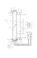
図2は定着装置Fの要部の拡大横断面模型図、図3は要部の正面模型図、図4はその縦断正面模型図である。
(2) Fixing device F
2 is an enlarged cross-sectional model view of the main part of the fixing device F, FIG. 3 is a front model view of the main part, and FIG. 4 is a longitudinal front model view thereof.
像加熱装置である定着装置Fは、電磁誘導加熱方式で発熱する加熱ローラ型の像加熱装置である。磁束により発熱する導電層を有する加熱ローラ1(像加熱部材)と、加熱ローラ1と記録材を挟持搬送するニップ部を形成する加圧部材としての加圧ローラ2を有するものである。
The fixing device F, which is an image heating device, is a heating roller type image heating device that generates heat by an electromagnetic induction heating method. It has a heating roller 1 (image heating member) having a conductive layer that generates heat by magnetic flux, and a
像加熱部材としての加熱ローラ1は、外径が40mm、厚さは0.8mm、長さ340mmである。加熱ローラ1は、キュリー温度が本実施例では210℃になるように鉄、ニッケル、クロム、マンガン等の材料を配合した、固有抵抗が約5Ω・mである整磁合金よりなる芯金1aを有する。また、表面のトナー離型性を高めるためにPFAやPTFE等のフッ素樹脂からなる厚さ30μmの表層1bを設けている。また、高画質なカラー画像を得るために、芯金1aと表層1bの間にシリコーンゴムなどの耐熱弾性層を設けても良い。
The
この加熱ローラ1はその両端部側をそれぞれ定着装置の手前側と奥側の側板(定着ユニットフレーム)21・22間に軸受23を介して回転可能に支持させて配設してある。また内空部には、上記の加熱ローラ1に誘導電流(渦電流)を誘起させてジュール発熱させるための高周波磁界を生じる、磁場発生手段としてのコイルユニット3を挿入して配置してある。
The
加圧ローラ2は、外径38mm、長さは330mmである。加熱ローラは、外径28mm、肉厚3mmの芯金2a、芯金2aの周面に形成される厚さ5mmの耐熱弾性層2b、および耐熱弾性層2bの周面に形成されるPFA、PTFEなどのフッ素樹脂より成る厚さ30μmの表層2cとから成る。
The
この加圧ローラ2は上記の加熱ローラ1の下側に並行に配列して、芯金2aの両端部側をそれぞれ定着装置の手前側と奥側の側板21・22間に軸受26を介して回転自在に保持させてある。
The
そして、上記の加熱ローラ1と加圧ローラ2を互いに不図示の加圧機構によって弾性体層2bの弾性に抗して圧接させて、該両ローラ1・2間に記録材Pを挟持搬送する幅が約5mmのニップ部Nを形成させている。
The
ここで、本発明において、装置構成部材についてその長手方向とは、定着ニップ部Nを含む平面において記録材Pの搬送方向に対して直交する方向としている。すなわち、加熱ローラ1の回転軸線方向である。また、中央部及び端部は、その長手方向の中央部及び端部である。
Here, in the present invention, the longitudinal direction of the apparatus constituent member is a direction orthogonal to the conveyance direction of the recording material P on a plane including the fixing nip portion N. That is, it is the direction of the rotation axis of the
加熱ローラ1の内空部に挿入した磁束発生手段としてのコイルユニット3は、ボビン4、磁性材からなる芯材(磁性コア)5(1,2)、磁束を生ずるコイル6、絶縁部材製のステー7等の組み立て体である。磁性芯材5はボビン4に保持させてあり、コイル6はボビン4の周囲に電線を巻回して形成されている。このボビン4・磁性芯材5・コイル6のユニットをステー7に固定支持させてある。
The
上記のコイルユニット3は加熱ローラ1の内空部に設けられている。また、コイルユニット3が所定の角度姿勢でかつ加熱ローラ1の内面とコイル6との間に一定のギャップを保持するように取り付けられている。即ち、コイルユニット3のステー7の両端部7a・7a側をそれぞれ定着装置の手前側と奥側の保持部材24・25に非回転に固定支持させて配置してある。ボビン4・磁性芯材5・コイル6のユニットは加熱ローラ1の外部に露呈しないように収納されている。
The
磁性芯材5はフェライト、パーマロイ等の、高透磁率で残留磁束密度の低い材料であって、コイル6によって発生した磁束を加熱ローラ1に導く働きをする。本実施例における磁性芯材5は横断面T字型であり、T字の横棒部分と縦棒部分とを構成する2枚の板状磁性芯材5(1)と5(2)との組み合わせで構成させている。
The
コイル6は、図4のように、加熱ローラ1の長手方向に平行に延び、磁性芯材5を周回するようにボビン4の形状に合せて横長舟型に複数回巻回して両端で折り曲げられて巻かれるリッツ線を束ねたものである。また、コイル6は、加熱ローラ1の内周に沿うように湾曲して配置されている。6a・6bは上記コイル6の2本のリード線(コイル供給線)であり、ステー7の奥側から外部に引き出して、コイル6に高周波電流を供給する高周波インバーター(励磁回路)101に接続してある。
As shown in FIG. 4, the coil 6 extends in parallel with the longitudinal direction of the
11は加熱ローラ1の温度検知部材としてのサーミスタである。このサーミスタについては後述する。
Reference numeral 11 denotes a thermistor as a temperature detection member of the
12は定着前ガイド板であり、作像機構部側から定着装置Fに搬送された記録材Pを定着ニップ部Nの入口部に案内する。13は分離爪であり、定着ニップ部Nに導入されて定着ニップ部Nを出た記録材Pが加熱ローラ1に巻き付くのを抑え、加熱ローラ1から分離させる役目をする。14は定着後ガイド板であり、定着ニップ部Nの出口部を出た記録材Pを排紙案内する。
A
前記のボビン4、ステー7、分離爪13は耐熱および電気絶縁性エンジニアリング・プラスチックから形成されている。
The bobbin 4, the stay 7, and the
G1は加熱ローラ1の奥側の端部側に固着させた加熱ローラドライブギア(駆動伝達部材)である。このドライブギアG1に駆動源M1から伝達系を介して回転力が伝達されることで、加熱ローラ1が図2において矢印Aの時計方向に本実施例では300mm/secの周速度にて回転駆動される。加圧ローラ2は定着ニップ部Nでの加熱ローラ1との摩擦力で加熱ローラ1の回転駆動に従動して矢印の反時計方向Bに回転する。
G1 is a heating roller drive gear (drive transmission member) fixed to the inner end side of the
15は加熱ローラ1をクリーニングするクリーニング部材であるクリーニングウエブである。これは、クリーニングウエブ155aをロール巻きに保持したウエブ繰り出し軸部15bと、ウエブ巻取り軸部15cと、該両軸部15b・15c間のウエブ部分を加熱ローラ1の外面に押し付ける押し付けローラ15dからなる。押し付けローラ15dで加熱ローラ1に押し付けたウエブ部分で加熱ローラ1面にオフセットしたトナーが拭われて定着ローラ面が清掃される。加熱ローラ1に押し付けられるウエブ部分は繰り出し軸部15b側から巻取り軸部15c側にウエブ15aが少しずつ送られることで徐々に更新される。
A cleaning
本実施例では、通紙は中央基準で行われる。Sはその中央基準である。すなわち、いかなる記録材サイズでも、記録材の中央部が加熱ローラ軸方向中央部を通過することになる。本実施例の画像形成装置においては、通紙できる記録材の最大サイズ(以下、大サイズ紙と記す)は例えばA4横である。また通紙できる記録材の最小サイズ(以下、小サイズ紙と記す)は例えばB5Rである。P1はその大サイズ紙の通紙領域幅、P2は小サイズ紙の通紙領域幅である。 In the present embodiment, the sheet passing is performed based on the central reference. S is the central reference. That is, for any recording material size, the central portion of the recording material passes through the central portion in the heating roller axial direction. In the image forming apparatus of this embodiment, the maximum size of the recording material that can be passed (hereinafter referred to as large size paper) is, for example, A4 side. The minimum size of the recording material that can be passed (hereinafter referred to as small size paper) is, for example, B5R. P1 is the paper passing area width of the large size paper, and P2 is the paper passing area width of the small size paper.
前述のサーミスタ11は、小サイズ紙の通紙領域幅P2の略中央部に対応する定着ローラ中央部分に対向している。そして、加熱ローラ1を隔ててコイル6に向かい合うように、定着ローラ1の表面に対して弾性部材により押圧して弾性的に圧接させて配置してある。このサーミスタ11の加熱ローラ温度検知信号は制御部(CPU)100に入力する。
The thermistor 11 described above is opposed to the fixing roller central portion corresponding to the substantially central portion of the paper passing area width P2 of the small size paper. The surface of the fixing
画像形成装置の制御部100は装置のメイン電源スイッチのONにより装置を起動させて所定の立ち上げモードをスタートさせる。定着装置Fは駆動源M1の起動により加熱ローラ1の回転が開始される。この加熱ローラ1の回転に従動して加圧ローラ2も回転する。また制御部100は高周波回路である高周波インバーター101を起動させてコイル6に高周波電流を流す。これによりコイル6の周囲に高周波交番磁束が発生し、加熱ローラ1が電磁誘導発熱して所定の像加熱温度である定着温度、本実施例ではスタンバイ温度である200℃に向かって昇温していく。この加熱ローラ1の昇温がサーミスタ11で検知され、その検知温度情報が制御部100に入力する。
The
加熱ローラ1の温度が200℃に到達したら、作像可能状態(待機モード)となる。待機モードにおいては、制御部100は、加熱ローラ1の大サイズ紙通紙領域幅P1の略全域がスタンバイ温度200℃に維持するよう、高周波電流を制御する。本実施例では、加熱ローラ1が予め決められた目標温度を維持するようにコイルへの通電を制御する通電制御手段を有するものである。この通電制御手段は、制御部に入力されたサーミスタ11の出力と目標温度との差分に応じて、制御部が高周波インバータ−101の駆動を制御するものである。
When the temperature of the
そして、この待機モード中に画像形成信号が入力されると、記録材上にトナー像が形成される。そして、定着ニップ部Nに対して作像部側から未定着トナー像tを担持した記録材Pが導入されて定着ニップ部Nを挟持搬送されていく。そして、所定の定着温度に維持された加熱ローラ1の熱と定着ニップ部Nの加圧力で、未定着トナー像tが記録材Pの面に加熱定着される。
When an image formation signal is input during this standby mode, a toner image is formed on the recording material. Then, the recording material P carrying the unfixed toner image t is introduced from the image forming unit side to the fixing nip portion N, and is nipped and conveyed through the fixing nip portion N. Then, the unfixed toner image t is heated and fixed on the surface of the recording material P by the heat of the
本実施例における画像形成装置は、画像形成装置の周囲の温度(外気)を検知する環境センサー(環境検知部材)を備えている。この、環境センサーの検知温度に応じて、像加熱温度である定着温度を変更している。具体的には、通常の環境(本実施例においては18℃以上)である場合は、第一の像加熱モードである通常環境モードになる。即ち、環境センサーの出力が所定値以上の場合、本実施例では、環境センサーが18℃以上と判断した場合に、通常環境モードとなる。このモードでは、像加熱温度は200℃(第一の像加熱温度)に設定される。そして、制御部100は加熱ローラ1の表面温度を設定された温度である200℃に維持するよう周波数f1が20kHzの高周波電流を印加する。本実施例では、20kHzは最大周波数であり、この最大周波数と、予め設定されている最低周波数とをON,OFFする構成である。この場合には、高周波インバーターを複数有する構成にしてもいい。低温環境(本実施例においては18℃未満)である場合は、第二の像加熱モードである低温環境モードになる。このモードでは、第一の像加熱温度よりも高い温度の第二の像加熱温度に設定される。そして、制御部100は加熱ローラ1の表面温度を設定された温度である215℃に維持するよう、周波数f2が60kHzの高周波電流を印加する。本実施例では、60kHzは最大周波数であり、この最大周波数と、予め設定されている最低周波数とをON,OFFする構成である。なお、最大周波数と最小周波数の間で、検知された温度と目標温度との差分に応じて周波数を切り換える構成であっても問題ない。
The image forming apparatus according to the present exemplary embodiment includes an environment sensor (environment detection member) that detects a temperature (outside air) around the image forming apparatus. The fixing temperature, which is the image heating temperature, is changed according to the detected temperature of the environmental sensor. Specifically, in a normal environment (18 ° C. or higher in this embodiment), a normal environment mode that is the first image heating mode is set. That is, when the output of the environmental sensor is equal to or higher than a predetermined value, in this embodiment, when the environmental sensor determines that the temperature is 18 ° C. or higher, the normal environmental mode is set. In this mode, image heating temperature is set at 200 ° C. (first image heating temperature). And the
ここで、図5を用いて、導電部材である加熱ローラ芯金1aの電磁誘導発熱原理を説明する。コイル6には、高周波インバーター101から交流電流が印加され、これによってコイル6の周囲には矢印Hで示した磁束が生成消滅を繰り返す。磁束Hは、磁性芯材5(1,2)と芯金1aによって形成された磁路に沿って導かれる。コイル6が生成した磁束の変化に対して、芯金1a内では、磁束の変化を妨げる方向に磁束を発生するように渦電流が発生する。この渦電流を矢印Cで示す。
Here, the principle of electromagnetic induction heat generation of the heating roller core 1a, which is a conductive member, will be described with reference to FIG. An alternating current is applied to the coil 6 from the high-
この渦電流Cは、表皮効果により芯金1aのコイル6側の面に集中して流れ、芯金1aの表皮抵抗Rs(Ω)に比例した電力で発熱を生じる。 This eddy current C flows in a concentrated manner on the surface of the metal core 1a on the side of the coil 6 due to the skin effect, and generates heat with electric power proportional to the skin resistance Rs (Ω) of the metal core 1a.
ここで、コイル6に印加する交流電流の周波数f(Hz)、芯金1aの透磁率μ(H/m)、芯金1aの固有抵抗ρ(Ω・m)から得られる表皮深さδ(m)および表皮抵抗Rs(Ω)は、式1および式2で示される。
Here, the skin depth δ () obtained from the frequency f (Hz) of the alternating current applied to the coil 6, the magnetic permeability μ (H / m) of the cored bar 1a, and the specific resistance ρ (Ω · m) of the cored bar 1a. m) and skin resistance Rs (Ω) are expressed by

また、芯金1aに発生する電力Wは、芯金1aに誘導される渦電流をIf(A)として、式3で示される。
Further, the electric power W generated in the cored bar 1a is expressed by
以上より、芯金1aの発熱量を増加させるためには、渦電流Ifを大きくする、または表皮抵抗Rsを大きくすればよい。 As described above, in order to increase the heat generation amount of the core metal 1a, the eddy current If may be increased or the skin resistance Rs may be increased.
渦電流Ifを大きくするためには、励磁コイル6によって生成される磁束を強くする、あるいは磁束の変化を大きくすればいい。例えば、励磁コイル6の巻き数を増やしたり、磁性芯材5として、より高透磁率で残留磁束密度の低いものを用いると良い。また、磁性芯材5と芯金1aとのギャップdを少なくすることで、芯金1a中に導かれる磁束が増加するため、渦電流Ifを大きくすることが出来る。
In order to increase the eddy current If, the magnetic flux generated by the exciting coil 6 may be increased, or the change in the magnetic flux may be increased. For example, it is preferable to increase the number of turns of the exciting coil 6 or use a
一方、表皮抵抗Rsを大きくするためには、励磁コイル6に印加する交流電流の周波数fを高くするか、より透磁率μの高く、固有抵抗の高い材料の芯金1aとする。 On the other hand, in order to increase the skin resistance Rs, the frequency f of the alternating current applied to the exciting coil 6 is increased, or the core bar 1a is made of a material having a higher magnetic permeability μ and a higher specific resistance.
次にキュリー温度について説明する。一般に強磁性体は、材料固有のキュリー温度まで加熱されると、自発磁化を失い透磁率μが減少する。したがって、加熱ローラ1の導電部材である芯金1aの温度がキュリー温度を越えてしまうと、表皮抵抗Rsが減少する。その結果、芯金1aの発熱量Wが減少する。
Next, the Curie temperature will be described. In general, when a ferromagnetic material is heated to a Curie temperature unique to the material, it loses its spontaneous magnetization and the magnetic permeability μ decreases. Therefore, when the temperature of the cored bar 1a that is the conductive member of the
一般に抵抗値は式3で表されるとおり、周波数が一定の場合は透磁率μと抵抗率ρで決まり、一般に抵抗率は温度上昇に伴って緩やかに増加する。
In general, as represented by
ここで、加熱ローラ1の抵抗値(表皮抵抗)Rsは磁束発生手段を加熱ローラに装着したときのコイルに電流を流したときのコイルからみた加熱ローラのみかけの負荷抵抗に相当する。
Here, the resistance value (skin resistance) Rs of the
このみかけの抵抗値の測定方法、及び抵抗値の温度依存性は以下のように測定する。アジレント社製のLCRメータ(型番HP4194A)を用いて、周波数20kHzの交流を印加した際の加熱ローラの抵抗値を測定した。このとき、加熱ローラ1、磁束発生手段である励磁コイル、コアは像加熱装置に装着された状態で測定するものとする。このとき加熱ローラの温度を変えていき、温度と加熱ローラの抵抗値を同時にプロットしていくことで加熱ローラ1の抵抗値の温度特性曲線を得ることができる。
The apparent resistance value measurement method and the temperature dependence of the resistance value are measured as follows. Using an LCR meter (model number HP4194A) manufactured by Agilent, the resistance value of the heating roller when an alternating current with a frequency of 20 kHz was applied was measured. At this time, the
また、加熱ローラの温度を変えるには、恒温室に加熱ローラ1及び磁束発生手段を装置に装着させた位置関係に保った状態で、加熱ローラの温度を変化させる。そして、ローラ温度を高温室の温度に飽和させてから上記の測定法で抵抗値を測定する。
Further, in order to change the temperature of the heating roller, the temperature of the heating roller is changed while maintaining the positional relationship in which the
このように測定すると、抵抗値の温度依存性は図7のような曲線になる。 When measured in this way, the temperature dependence of the resistance value becomes a curve as shown in FIG.
また、透磁率の測定方法は以下のように行なう。岩通計測株式会社製のB−Hアナライザー(型番:SY−8232)を用いて測定した。測定試料に装置の所定の一次コイルと二次コイルを巻きつけて周波数20kHzで測定する。測定試料はコイルが巻きつけられる形状であれば構わない(透磁率の異なる温度同士の比率は殆ど変わらない)。 Moreover, the measuring method of a magnetic permeability is performed as follows. The measurement was performed using a BH analyzer (model number: SY-8232) manufactured by Iwatsu Measurement Co., Ltd. A predetermined primary coil and secondary coil of the apparatus are wound around the measurement sample, and measurement is performed at a frequency of 20 kHz. The measurement sample may be in a shape around which a coil is wound (the ratio between temperatures having different magnetic permeability is hardly changed).
試料にコイルを設定したら、恒温室に試料を入れて温度を飽和させ、その温度における透磁率をプロットする。恒温室の温度を変えてやることで透磁率の温度依存性曲線が得られる。恒温室の温度を上昇させていき、ある温度で透磁率が変化しなくなる。この透磁率が変化しなくなった温度をキュリー温度とみなす。 After setting the coil to the sample, put the sample in a constant temperature room to saturate the temperature, and plot the permeability at that temperature. The temperature dependence curve of permeability can be obtained by changing the temperature of the temperature-controlled room. The temperature of the temperature-controlled room is raised, and the permeability does not change at a certain temperature. The temperature at which the magnetic permeability does not change is regarded as the Curie temperature.
このように測定すると透磁率の温度依存性は図7のような曲線になる。 When measured in this way, the temperature dependence of the magnetic permeability becomes a curve as shown in FIG.
図6に示すように、芯金1aの厚さdが、芯金1aの温度がキュリー温度を越えた時の表皮深さδcと比較して狭い場合は、芯金1aの断面のおよそすべてに渦電流が流れるため、発熱量が減少する。この状態では、加熱ローラ1の温度上昇はほぼ停止し、加熱ローラ1の表面温度は芯金1aに用いた整磁合金のキュリー温度とほぼ等しくなる。
As shown in FIG. 6, when the thickness d of the cored bar 1a is narrower than the skin depth δc when the temperature of the cored bar 1a exceeds the Curie temperature, approximately all of the cross section of the cored bar 1a Since eddy current flows, the amount of heat generation decreases. In this state, the temperature rise of the
以上より、コイル6に印加する高周波電流が、所定の周波数fにあっては、加熱ローラ1の表面温度はキュリー温度よりも高くすることが困難である。
As described above, when the high-frequency current applied to the coil 6 is at the predetermined frequency f, it is difficult to make the surface temperature of the
一方で、励磁コイルに印加する高周波電流の周波数を、通常モードの周波数よりも大きくすれば、キュリー温度を越えた状態での表皮深さδcが小さくすることができる。そのため、キュリー温度を越えた状態でも発熱量を増加させることが可能となりなる。また、加熱ローラ1の表面温度をキュリー温度より実質的に高くすることが可能となる。このことは、特殊紙モードの定着温度がキュリー温度に近い温度に設定されている場合においても、同様の効果を得ることができる。キュリー温度を越えたときの表皮深さδcが、芯金1aの厚さdよりも少なければ、キュリー温度を越えた場合における発熱量を通常状態よりも増加させることが可能となる。その結果、加熱ローラ1の表面温度をキュリー温度よりも高くすることが可能となり、厚紙やコート紙等の、通常の用紙よりも高いエネルギーが必要な用紙に対しても、加熱定着に必要なエネルギーを与えることが可能となる。
On the other hand, if the frequency of the high-frequency current applied to the exciting coil is made larger than the frequency in the normal mode, the skin depth δc in the state exceeding the Curie temperature can be reduced. Therefore, it is possible to increase the amount of heat generated even when the temperature exceeds the Curie temperature. Further, the surface temperature of the
また、通常モードの周波数を像加熱中に発熱量を大きくする設定にすると、小サイズの記録材を連続通紙する際の非通紙部昇温の上昇速度が速くなる問題が生ずる。非通紙部昇温の上昇速度を遅くするためには、像加熱動作中の発熱量は大きすぎない構成がいい。 Further, if the frequency in the normal mode is set to increase the amount of heat generated during image heating, there arises a problem that the rising speed of the temperature increase in the non-sheet passing portion when a small-sized recording material is continuously fed is increased. In order to slow down the rising speed of the temperature rise of the non-sheet passing portion, it is preferable that the amount of heat generated during the image heating operation is not too large.
以上のことから、通常環境モードにおける高周波電流の最大周波数f1と、低温環境モードにおける高周波電流の最大周波数f2とを、 From the above, the maximum frequency f1 of the high-frequency current in the normal environment mode and the maximum frequency f2 of the high-frequency current in the low-temperature environment mode are
を満たすように設定することで、低温環境においても加熱定着に必要なエネルギーを与えることが可能となり、かつ非通紙部昇温を防止もしくは低減することが可能となる。 By setting so as to satisfy, it becomes possible to give energy necessary for heat fixing even in a low temperature environment, and it is possible to prevent or reduce the temperature rise of the non-sheet passing portion.
図9に本実施例のフローチャートを示す。まず、画像形成信号が入力されると、制御部で環境モードの選択をフローが開始される(S0001)。そして、制御部が環境センサーで検知される温度を検出する。制御部は、その温度が18℃以上か否かの判断を行う(S0002)。そして、検知された温度が18℃以上のときには通常環境モードが選択される(S0003)。通常環境モードが選択された場合には、像加熱温度を200℃、周波数を20kHzに設定される(S0003)。そして、画像形成が開始される(S0005)。一方、検知された温度が18℃未満である場合には、像加熱温度を220℃、周波数を60kHzに設定される(S0004)。そして、画像形成が開始される(S0005)。 FIG. 9 shows a flowchart of this embodiment. First, when an image formation signal is input, the control unit starts a flow for selecting an environmental mode (S0001). Then, the control unit detects the temperature detected by the environmental sensor. The control unit determines whether the temperature is 18 ° C. or higher (S0002). When the detected temperature is 18 ° C. or higher, the normal environment mode is selected (S0003). When the normal environment mode is selected, the image heating temperature is set to 200 ° C., and the frequency is set to 20 kHz (S0003). Then, image formation is started (S0005). On the other hand, if the detected temperature is less than 18 ° C., the image heating temperature is set to 220 ° C. and the frequency is set to 60 kHz (S0004). Then, image formation is started (S0005).
本実施例では、画像形成信号が入力されたときに、環境センサーで検知される温度を検出したものであるが、画像形成装置がONしたときに検出する構成や所定時間毎といった所定のタイミングで検出する構成であっても同様の効果をえることができる。 In this embodiment, the temperature detected by the environmental sensor is detected when an image forming signal is input, but at a predetermined timing such as a configuration that is detected when the image forming apparatus is turned on or every predetermined time. Even if it is the structure to detect, the same effect can be acquired.
本実施例では整磁合金のキュリー温度を210℃、通常環境で用いられる通常モードにおける像加熱温度を200℃、低温環境で用いられる低音モードにおける像加熱温度を220℃として説明した。しかし、本発明はこれに限らず、使用するトナーや定着装置の構成によってキュリー温度を最適になるよう設定しても、本発明は適応可能である。また、搬送される紙の厚みや加熱ローラの畜熱状態によっては定着温度を複数有しても本発明は適応可能である。また、それぞれのモードにおいて印加する高周波電流の周波数も、使用する整磁合金や高周波電源、加熱装置の構成等によって適時最適な周波数を選択して良い。 In this embodiment, the Curie temperature of the magnetic shunt alloy is 210 ° C., the image heating temperature in the normal mode used in the normal environment is 200 ° C., and the image heating temperature in the low sound mode used in the low temperature environment is 220 ° C. However, the present invention is not limited to this, and the present invention can be applied even if the Curie temperature is set to be optimal depending on the toner used and the configuration of the fixing device. Further, the present invention can be applied even if there are a plurality of fixing temperatures depending on the thickness of the paper to be conveyed and the state of heat of the heating roller. Further, the frequency of the high-frequency current applied in each mode may be selected as the optimum frequency in a timely manner depending on the magnetic shunt alloy used, the high-frequency power source, the configuration of the heating device, and the like.
また、本実施例では、加熱ローラを用いた熱ローラ加熱装置であるが、エンドレスベルトを用いたベルト加熱方式等にも適用できることは自明である。また、複数の異なる金属を積層させたクラッドローラを用いる場合も、整磁合金の層が少なくとも1層備えれば、本発明を適用可能である。 In this embodiment, the heating roller heating device using a heating roller is used, but it is obvious that the present invention can be applied to a belt heating method using an endless belt. Further, when using a clad roller in which a plurality of different metals are laminated, the present invention can be applied if at least one layer of a magnetic shunt alloy is provided.
以上、本発明により、像加熱部材の温度をキュリー温度より高い像加熱モードでの発熱を大きくしながらも、像加熱部材の温度がキュリー温度よりも低いモードにおける非通紙部昇温を低減することができる。 As described above, the present invention reduces the temperature rise of the non-sheet passing portion in the mode in which the temperature of the image heating member is lower than the Curie temperature, while increasing the heat generation in the image heating mode in which the temperature of the image heating member is higher than the Curie temperature. be able to.
以上本発明の実施例について説明したが、本発明は上記実施例に何ら限定されるものではなく、本発明の技術思想内であらゆる変形が可能である。 Although the embodiments of the present invention have been described above, the present invention is not limited to the above-described embodiments, and various modifications can be made within the technical idea of the present invention.
1 加熱ローラ(導電部材)
2 加圧ローラ
3 コイルユニット(磁場発生手段)
5 磁性芯材(磁性コア)
6 コイル
11 サーミスタ(温度検知手段)
41 感光体(感光ドラム)
42 一次帯電器
43 レーザービームスキャナ
44 現像器
45 転写ローラ
46 クリーニング装置
F 定着装置
P記録材(被加熱材)、t トナー像
1 Heating roller (conductive member)
2
5 Magnetic core material (magnetic core)
6 Coil 11 Thermistor (Temperature detection means)
41 photoconductor (photosensitive drum)
42 Primary Charger 43
Claims (2)
像加熱部材のキュリー温度は、第一の像加熱温度よりも高く、第二の像加熱温度よりも低い温度であり、第二の像加熱モードにおける高周波電流の最大周波数は第一の像加熱モードにおける高周波電流の最大周波数よりも大きいことを特徴とする像加熱装置。 Coil and a high frequency circuit for forming a high-frequency current supplied to the coil generates heat by a magnetic flux generated by the high frequency current applied to the coil, and the image heating member for heating the image on the recording paper, image heating member has a current supply control means for temperature controlling the frequency of the high frequency current applied to said coil to a predetermined image heating temperature, and environmental detection member for detecting the outside air temperature, the detection by the environment detection member temperature first temperature sensed with the image heating mode by the environment detecting member for heating an image on a recording material at a first image heating temperature when temperature is above a temperature set in advance is set in advance in the first image heating apparatus capable of performing a second image heating mode for heating an image on a recording material with a high second image heating temperature than the image heated temperature when less than,
Curie temperature of the image heating member is higher than the first image heating temperature is a temperature lower than the second image heating temperature, the maximum frequency of the high frequency current in the second image heating mode of the first image heating mode An image heating apparatus characterized by being larger than the maximum frequency of the high-frequency current in.
Priority Applications (1)
| Application Number | Priority Date | Filing Date | Title |
|---|---|---|---|
| JP2007313572A JP5196977B2 (en) | 2007-12-04 | 2007-12-04 | Image heating device |
Applications Claiming Priority (1)
| Application Number | Priority Date | Filing Date | Title |
|---|---|---|---|
| JP2007313572A JP5196977B2 (en) | 2007-12-04 | 2007-12-04 | Image heating device |
Publications (2)
| Publication Number | Publication Date |
|---|---|
| JP2009139477A JP2009139477A (en) | 2009-06-25 |
| JP5196977B2 true JP5196977B2 (en) | 2013-05-15 |
Family
ID=40870171
Family Applications (1)
| Application Number | Title | Priority Date | Filing Date |
|---|---|---|---|
| JP2007313572A Expired - Fee Related JP5196977B2 (en) | 2007-12-04 | 2007-12-04 | Image heating device |
Country Status (1)
| Country | Link |
|---|---|
| JP (1) | JP5196977B2 (en) |
Family Cites Families (6)
| Publication number | Priority date | Publication date | Assignee | Title |
|---|---|---|---|---|
| JP3926555B2 (en) * | 2000-11-17 | 2007-06-06 | 株式会社リコー | Rotating body for heating, heating device, fixing device, and image forming apparatus |
| JP2007004021A (en) * | 2005-06-27 | 2007-01-11 | Canon Inc | Image fixing unit |
| JP2007017723A (en) * | 2005-07-08 | 2007-01-25 | Ricoh Co Ltd | Heating device, fixing device, and image forming apparatus |
| JP5102079B2 (en) * | 2007-05-15 | 2012-12-19 | 株式会社東芝 | Fixing apparatus, image forming apparatus, and heating control method |
| JP2009003264A (en) * | 2007-06-22 | 2009-01-08 | Canon Inc | Image heating device and image forming apparatus with image heating device |
| JP5031457B2 (en) * | 2007-06-25 | 2012-09-19 | キヤノン株式会社 | Image heating apparatus and image forming apparatus provided with image heating apparatus |
-
2007
- 2007-12-04 JP JP2007313572A patent/JP5196977B2/en not_active Expired - Fee Related
Also Published As
| Publication number | Publication date |
|---|---|
| JP2009139477A (en) | 2009-06-25 |
Similar Documents
| Publication | Publication Date | Title |
|---|---|---|
| JP5503248B2 (en) | Image heating device | |
| JP4636870B2 (en) | Image heating device | |
| JP4448016B2 (en) | Image heating device | |
| US9482997B2 (en) | Image forming apparatus executing a start-up process of a fixing portion, when a detecting portion detects the existence of an operator before receipt of an image formation instruction | |
| JP6137893B2 (en) | Heating apparatus and image forming apparatus | |
| JP6071306B2 (en) | Image heating device | |
| JP2002123107A (en) | Induction heating type image heating device | |
| JP2011090087A (en) | Image heating device | |
| JP2006119410A (en) | Fixing device and image forming apparatus | |
| JP5207775B2 (en) | Fixing device | |
| JP5800688B2 (en) | Image heating device | |
| JP5031457B2 (en) | Image heating apparatus and image forming apparatus provided with image heating apparatus | |
| JP5656376B2 (en) | Electromagnetic induction heating system | |
| JP5523049B2 (en) | Image heating device | |
| JP4708878B2 (en) | Image heating device | |
| JP5791358B2 (en) | Image heating apparatus and image forming apparatus | |
| JP5196977B2 (en) | Image heating device | |
| JP2009003264A (en) | Image heating device and image forming apparatus with image heating device | |
| JP5031326B2 (en) | Image forming apparatus provided with electromagnetic induction heating device | |
| JP6904671B2 (en) | Image forming device | |
| JP2006293080A (en) | Image heating apparatus | |
| JP2016080889A (en) | Image heating device | |
| JP2022067934A (en) | Image forming apparatus | |
| JP2013130707A (en) | Image heating device | |
| JP2007041130A (en) | Fixing device |
Legal Events
| Date | Code | Title | Description |
|---|---|---|---|
| RD04 | Notification of resignation of power of attorney |
Free format text: JAPANESE INTERMEDIATE CODE: A7424 Effective date: 20100201 |
|
| RD01 | Notification of change of attorney |
Free format text: JAPANESE INTERMEDIATE CODE: A7421 Effective date: 20100630 |
|
| A621 | Written request for application examination |
Free format text: JAPANESE INTERMEDIATE CODE: A621 Effective date: 20101124 |
|
| A131 | Notification of reasons for refusal |
Free format text: JAPANESE INTERMEDIATE CODE: A131 Effective date: 20121016 |
|
| A521 | Written amendment |
Free format text: JAPANESE INTERMEDIATE CODE: A523 Effective date: 20121217 |
|
| TRDD | Decision of grant or rejection written | ||
| A01 | Written decision to grant a patent or to grant a registration (utility model) |
Free format text: JAPANESE INTERMEDIATE CODE: A01 Effective date: 20130108 |
|
| A61 | First payment of annual fees (during grant procedure) |
Free format text: JAPANESE INTERMEDIATE CODE: A61 Effective date: 20130205 |
|
| FPAY | Renewal fee payment (event date is renewal date of database) |
Free format text: PAYMENT UNTIL: 20160215 Year of fee payment: 3 |
|
| R151 | Written notification of patent or utility model registration |
Ref document number: 5196977 Country of ref document: JP Free format text: JAPANESE INTERMEDIATE CODE: R151 |
|
| FPAY | Renewal fee payment (event date is renewal date of database) |
Free format text: PAYMENT UNTIL: 20160215 Year of fee payment: 3 |
|
| LAPS | Cancellation because of no payment of annual fees |