JP5196397B2 - Hydrostatic gas bearing spindle - Google Patents
Hydrostatic gas bearing spindle Download PDFInfo
- Publication number
- JP5196397B2 JP5196397B2 JP2007289361A JP2007289361A JP5196397B2 JP 5196397 B2 JP5196397 B2 JP 5196397B2 JP 2007289361 A JP2007289361 A JP 2007289361A JP 2007289361 A JP2007289361 A JP 2007289361A JP 5196397 B2 JP5196397 B2 JP 5196397B2
- Authority
- JP
- Japan
- Prior art keywords
- hole
- vent
- gas bearing
- static pressure
- liquid
- Prior art date
- Legal status (The legal status is an assumption and is not a legal conclusion. Google has not performed a legal analysis and makes no representation as to the accuracy of the status listed.)
- Active
Links
Images


Classifications
-
- F—MECHANICAL ENGINEERING; LIGHTING; HEATING; WEAPONS; BLASTING
- F16—ENGINEERING ELEMENTS AND UNITS; GENERAL MEASURES FOR PRODUCING AND MAINTAINING EFFECTIVE FUNCTIONING OF MACHINES OR INSTALLATIONS; THERMAL INSULATION IN GENERAL
- F16C—SHAFTS; FLEXIBLE SHAFTS; ELEMENTS OR CRANKSHAFT MECHANISMS; ROTARY BODIES OTHER THAN GEARING ELEMENTS; BEARINGS
- F16C32/00—Bearings not otherwise provided for
- F16C32/06—Bearings not otherwise provided for with moving member supported by a fluid cushion formed, at least to a large extent, otherwise than by movement of the shaft, e.g. hydrostatic air-cushion bearings
- F16C32/0681—Construction or mounting aspects of hydrostatic bearings, for exclusively rotary movement, related to the direction of load
- F16C32/0696—Construction or mounting aspects of hydrostatic bearings, for exclusively rotary movement, related to the direction of load for both radial and axial load
-
- F—MECHANICAL ENGINEERING; LIGHTING; HEATING; WEAPONS; BLASTING
- F16—ENGINEERING ELEMENTS AND UNITS; GENERAL MEASURES FOR PRODUCING AND MAINTAINING EFFECTIVE FUNCTIONING OF MACHINES OR INSTALLATIONS; THERMAL INSULATION IN GENERAL
- F16C—SHAFTS; FLEXIBLE SHAFTS; ELEMENTS OR CRANKSHAFT MECHANISMS; ROTARY BODIES OTHER THAN GEARING ELEMENTS; BEARINGS
- F16C32/00—Bearings not otherwise provided for
- F16C32/06—Bearings not otherwise provided for with moving member supported by a fluid cushion formed, at least to a large extent, otherwise than by movement of the shaft, e.g. hydrostatic air-cushion bearings
- F16C32/0603—Bearings not otherwise provided for with moving member supported by a fluid cushion formed, at least to a large extent, otherwise than by movement of the shaft, e.g. hydrostatic air-cushion bearings supported by a gas cushion, e.g. an air cushion
- F16C32/0614—Bearings not otherwise provided for with moving member supported by a fluid cushion formed, at least to a large extent, otherwise than by movement of the shaft, e.g. hydrostatic air-cushion bearings supported by a gas cushion, e.g. an air cushion the gas being supplied under pressure, e.g. aerostatic bearings
Landscapes
- Engineering & Computer Science (AREA)
- General Engineering & Computer Science (AREA)
- Mechanical Engineering (AREA)
- Sealing Of Bearings (AREA)
- Jigs For Machine Tools (AREA)
- Turning (AREA)
- Sealing Using Fluids, Sealing Without Contact, And Removal Of Oil (AREA)
- Magnetic Bearings And Hydrostatic Bearings (AREA)
Description
本発明は、静圧気体軸受スピンドルに関し、特に、回転部に対象物を吸着固定する吸着機構を備える、静圧気体軸受スピンドルに関する。 The present invention relates to a static pressure gas bearing spindle, and more particularly to a static pressure gas bearing spindle including an adsorption mechanism that adsorbs and fixes an object to a rotating part.
静圧気体軸受スピンドルでは、回転部と固定部との間の微小なすき間に加圧気体が供給されて構成される静圧気体軸受を介して、回転部が固定部に対して非接触の状態で支持される。そのため、軸受における摩擦損失が小さく、回転部が高速で回転する場合の発熱も少ない。また、精度の高い滑らかな回転運動が可能であり、正常な運転状態である限り、材料の疲労や摩耗が生じない。このような特徴を生かして、静圧気体軸受スピンドルは、高精度スピンドルや高速スピンドルとして広く使用されている。 In the static pressure gas bearing spindle, the rotating part is not in contact with the fixed part via the static pressure gas bearing configured by supplying pressurized gas to the minute gap between the rotating part and the fixed part. Supported by Therefore, the friction loss in the bearing is small, and the heat generated when the rotating part rotates at high speed is small. In addition, high-accuracy and smooth rotational movement is possible, and as long as it is in a normal operating state, fatigue and wear of the material do not occur. Taking advantage of such characteristics, the static pressure gas bearing spindle is widely used as a high-precision spindle or a high-speed spindle.
精密加工装置、精密検査装置などに用いられる静圧気体軸受スピンドルにおいては、被加工物、被検査物または工具などの対象物を回転部に固定する、対象物固定手段を備える場合がある。特に、精密加工装置に用いられる場合、切削または研削を行なうために、回転部の回転軸方向の端部に被加工物を吸着固定する、吸着機構が必要になる。 A static pressure gas bearing spindle used in a precision machining apparatus, a precision inspection apparatus, or the like may include an object fixing means for fixing an object such as a workpiece, an inspection object, or a tool to a rotating portion. In particular, when used in a precision processing apparatus, in order to perform cutting or grinding, an adsorption mechanism for adsorbing and fixing a workpiece to the end portion in the rotation axis direction of the rotation unit is necessary.
吸着機構とは、真空チャック機構とも称され、対象物を吸着固定する回転部の表面(ワークチャック面)に連通する通路である真空吸気通路を、真空発生機、たとえば真空ポンプなどを用いて排気することにより、真空吸気通路の内部に負圧を発生させ、対象物(ワーク)を吸着する機構である。従来の吸着機構を備える静圧気体軸受スピンドルは、たとえば特許文献1に開示されている。
The suction mechanism is also referred to as a vacuum chuck mechanism, and the vacuum intake passage, which is a passage communicating with the surface of the rotating part (work chuck surface) for sucking and fixing an object, is exhausted using a vacuum generator such as a vacuum pump. By doing this, it is a mechanism that generates a negative pressure inside the vacuum intake passage and sucks the object (workpiece). A static pressure gas bearing spindle provided with a conventional adsorption mechanism is disclosed in, for example,
また、吸着機構を備える静圧気体軸受スピンドルが精密加工装置に搭載され、回転部に吸着固定されたワークの切削や研削を行なう場合、ワークと刃物との間の摩擦を軽減するため、また摩擦熱によるワークの加熱を抑制するため、加工液が用いられる場合がある。この場合、静圧気体軸受内部への加工液の浸入を防ぐシール機構が必要になる。さらにこのシール機構では、固定部は回転部に対し非接触でなくてはならない。つまり、シール機構は、回転部と固定部との間に設けられた微小なシール隙間を含む構成とされる。従来のシール機構を備える静圧気体軸受スピンドルは、たとえば特許文献2に開示されている。
特許文献2で提案されている静圧気体軸受スピンドルでは、静圧気体軸受への加工液の浸入が抑制される。しかしながら、真空吸気通路の内部を減圧するときワークチャック面側から空気とともに真空吸気通路内に吸い込まれる加工液の、シール隙間への浸入を抑制することはできない。シール隙間は数μm〜十数μm程度の微小な隙間であるため、シール隙間へ加工液が浸入すると、シール隙間の損傷、または静圧気体軸受の損傷が発生するおそれがある。
In the static pressure gas bearing spindle proposed in
本発明は上記の問題に鑑みてなされたものであり、その主たる目的は、吸着機構を備える静圧気体軸受スピンドルにおいて、シール隙間への加工液の浸入を抑制することができる、静圧気体軸受スピンドルを提供することである。 The present invention has been made in view of the above problems, and a main object thereof is a static pressure gas bearing capable of suppressing the intrusion of a working fluid into a seal gap in a static pressure gas bearing spindle having an adsorption mechanism. Is to provide a spindle.
本発明の一の局面に係る静圧気体軸受スピンドルは、貫通孔の形成された回転部を備える。また、静圧気体軸受を介して回転部を回転可能に支持する固定部を備える。また、貫通孔の内部を減圧して、貫通孔の一方の端部が開口する回転部の表面に対象物を吸着固定する、吸着機構を備える。固定部の外壁には、貫通孔の内部の圧力を変化させるための気体が流通する、通気口が形成されている。回転部と固定部との間には、通気口と静圧気体軸受とを隔てるシール隙間が形成されている。また、通気口とシール隙間とが連通する通路に設けられており、貫通孔の内部を通気口側へ流れる液体のシール隙間への浸入を抑制する、液流抑制部をさらに備える。回転部は、貫通孔が通気口側へ開口する他方の端部において貫通孔の径が拡大されている、拡径端部を含み、液流抑制部は拡径端部を含む。 A static pressure gas bearing spindle according to one aspect of the present invention includes a rotating portion in which a through hole is formed. Moreover, the fixing | fixed part which supports a rotation part rotatably via a static pressure gas bearing is provided. In addition, a suction mechanism is provided that depressurizes the inside of the through hole and sucks and fixes the object to the surface of the rotating portion where one end of the through hole opens. The outer wall of the fixed part is formed with a vent hole through which a gas for changing the pressure inside the through hole flows. A seal gap is formed between the rotating part and the fixed part to separate the vent and the static pressure gas bearing. Moreover, the liquid flow control part is further provided in the channel | path which the air vent and the seal | sticker clearance space communicate, and suppresses the penetration | invasion to the seal | sticker clearance gap of the liquid which flows through the inside of a through-hole. The rotating part includes an enlarged end part in which the diameter of the through hole is enlarged at the other end part where the through hole opens to the vent hole side, and the liquid flow suppressing part includes an enlarged end part.
本発明の他の局面に係る静圧気体軸受スピンドルは、貫通孔の形成された回転部を備える。また、静圧気体軸受を介して回転部を回転可能に支持する固定部を備える。また、貫通孔の内部を減圧して、貫通孔の一方の端部が開口する回転部の表面に対象物を吸着固定する、吸着機構を備える。固定部の外壁には、貫通孔の内部の圧力を変化させるための気体が流通する、通気口が形成されている。回転部と固定部との間には、通気口と静圧気体軸受とを隔てるシール隙間が形成されている。また、通気口とシール隙間とが連通する通路に設けられており、貫通孔の内部を通気口側へ流れる液体のシール隙間への浸入を抑制する、液流抑制部をさらに備える。液流抑制部は、回転部の径が拡大されている鍔部を含む。A hydrostatic gas bearing spindle according to another aspect of the present invention includes a rotating portion in which a through hole is formed. Moreover, the fixing | fixed part which supports a rotation part rotatably via a static pressure gas bearing is provided. In addition, a suction mechanism is provided that depressurizes the inside of the through hole and sucks and fixes the object to the surface of the rotating portion where one end of the through hole opens. The outer wall of the fixed part is formed with a vent hole through which a gas for changing the pressure inside the through hole flows. A seal gap is formed between the rotating part and the fixed part to separate the vent and the static pressure gas bearing. Moreover, the liquid flow control part is further provided in the channel | path which the air vent and the seal | sticker clearance space communicate, and suppresses the penetration | invasion to the seal | sticker clearance gap of the liquid which flows through the inside of a through-hole. The liquid flow suppressing portion includes a flange portion in which the diameter of the rotating portion is enlarged.
また、シール隙間に加圧気体を供給する加圧気体供給機構をさらに備え、加圧気体の少なくとも一部はシール隙間から通気口へ向かう方向へ流れるものであってもよい。 Also, further comprising a pressurized gas supply mechanism for supplying a pressurized gas into the sealing gap, at least a portion of the pressurized gas may be one that flows in a direction toward the seal gap to vent.
また、回転部は、貫通孔の径が通気口へ向かって縮小している縮径部を含んでもよい。
また、液体を一時的に溜める液溜め部をさらに備えてもよい。
The rotating part may include a reduced diameter part in which the diameter of the through hole is reduced toward the vent.
Moreover, you may further provide the liquid storage part which stores a liquid temporarily.
また、液溜め部を構成する壁面の少なくとも一部は、透明な材質により形成されていてもよい。 Further, at least a part of the wall surface constituting the liquid reservoir may be formed of a transparent material.
また、液溜め部を構成する壁面の少なくとも一部は、着脱可能に形成されていてもよい。 Further, at least a part of the wall surface constituting the liquid reservoir may be detachable.
また、液溜め部から液体を排出するための配管をさらに備えてもよい。 Moreover, you may further provide piping for discharging | emitting a liquid from a liquid reservoir part.
本発明の静圧気体軸受スピンドルによると、貫通孔の内部の圧力を変化させるための気体が流通する通気口とシール隙間とが連通する通路に、液流抑制部が設けられている。液流抑制部は、貫通孔の内部を通気口側へ流れる液体のシール隙間への浸入を抑制する機能を有している。よって、貫通孔の内部を減圧するとき、貫通孔の内部に加工液などの液体が空気とともに吸い込まれても、液体のシール隙間への浸入は抑制される。また、シール隙間は通気口と静圧気体軸受とを隔てるものであるから、静圧気体軸受への液体の浸入も抑制される。 According to the static pressure gas bearing spindle of the present invention, the liquid flow suppressing portion is provided in the passage where the vent through which the gas for changing the pressure in the through hole flows and the seal gap communicate with each other. The liquid flow suppression unit has a function of suppressing the penetration of the liquid flowing through the through hole toward the vent into the seal gap. Therefore, when the inside of the through hole is decompressed, even if a liquid such as a machining liquid is sucked into the through hole together with the air, the penetration of the liquid into the seal gap is suppressed. Further, since the seal gap separates the vent and the static pressure gas bearing, the infiltration of liquid into the static pressure gas bearing is also suppressed.
そのため、対象物の加工時に発生する切粉などの異物が加工液に含まれていても、異物がシール隙間や静圧気体軸受へ入り込むことを抑制することができる。したがって、シール隙間や静圧気体軸受において固定部と回転部との間にかじりなどの損傷が発生することを抑制することができ、シール隙間および静圧気体軸受の損傷を抑制することができる。その結果、静圧気体軸受スピンドルの性能の劣化を抑制することができ、また、メンテナンスの必要性を軽減することができる。 For this reason, even if foreign matter such as chips generated during processing of the object is contained in the machining fluid, foreign matter can be prevented from entering the seal gap or the static pressure gas bearing. Accordingly, it is possible to suppress the occurrence of galling or the like between the fixed portion and the rotating portion in the seal gap or the static pressure gas bearing, and it is possible to suppress damage to the seal gap and the static pressure gas bearing. As a result, the deterioration of the performance of the static pressure gas bearing spindle can be suppressed, and the necessity for maintenance can be reduced.
以下、図面に基づいてこの発明の実施の形態を説明する。なお、以下の図面において、同一または相当する部分には同一の参照番号を付し、その説明は繰返さない。 Embodiments of the present invention will be described below with reference to the drawings. In the following drawings, the same or corresponding parts are denoted by the same reference numerals, and description thereof will not be repeated.
(実施の形態1)
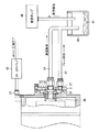
図1は、本発明の実施の形態1の静圧気体軸受スピンドルの構成を示す断面模式図である。図2は、図1に示す領域II付近を拡大して示す断面図である。図1に示すように、静圧気体軸受スピンドルは、回転軸1とハウジング2とを備える。回転軸1は、静圧気体軸受スピンドルの回転部に含まれる。ハウジング2の内部には、中空円筒形状の軸受スリーブ3が設置されている。ハウジング2は、軸受スリーブ3の外周側面を取り囲んで設けられている。軸受スリーブ3は、たとえば焼嵌めによって、ハウジング2へ固定することができる。
(Embodiment 1)
FIG. 1 is a schematic cross-sectional view showing a configuration of a static pressure gas bearing spindle according to
軸受スリーブ3の内周側面と、当該内周側面と対向する回転軸1の円筒形状の外周側面とは、回転軸1の回転中心軸に平行な円筒形状のジャーナル軸受面を含む。軸受スリーブ3のジャーナル軸受面と、回転軸1のジャーナル軸受面と、軸受スリーブ3と回転軸1との間のジャーナル軸受隙間とは、回転軸1を少なくとも半径方向に支持する、静圧気体ジャーナル軸受15を構成する。
The inner peripheral side surface of the
回転軸1は、ハウジング2の内部に設置された複数の円板形状のスラスト板4を含む。スラスト板4は、軸受スリーブ3と対向する側の軸方向の表面において、回転軸1の回転中心軸に垂直な円環形状のスラスト軸受面を含む。また軸受スリーブ3は、スラスト板4と対向する端面において、スラスト軸受面を含む。軸受スリーブ3のスラスト軸受面と、スラスト板4のスラスト軸受面と、軸受スリーブ3とスラスト板4との間のスラスト軸受隙間とは、回転軸1を少なくとも軸方向に支持する、一対の静圧気体スラスト軸受16を構成する。
The rotating
軸受スリーブ3およびハウジング2の内部には、支持用気体供給路が形成されている。支持用気体供給路は、ハウジング2の外部において、支持用気体供給口23に連結されている。圧縮空気などの支持用気体は、図示しないエアコンプレッサなどの支持用気体供給源から、支持用気体供給口23に供給される。支持用気体は、支持用気体供給路とジャーナル軸受給気絞りとを経由してジャーナル軸受隙間に供給され、また支持用気体供給路とスラスト軸受給気絞りとを経由してスラスト軸受隙間に供給される。
A supporting gas supply path is formed in the
ジャーナル軸受隙間およびスラスト軸受隙間から流出する支持用気体は、ハウジング2および軸受スリーブ3の内部に形成された排気路と、排気口29とを経由して、ハウジング2の外部に排出される。
The supporting gas that flows out from the journal bearing gap and the thrust bearing gap is discharged to the outside of the
ハウジング2およびハウジング9の内部には、他の給気路が形成されている。圧縮空気などの圧縮気体は、他の給気口24と他の給気路とを経由して、スラスト軸受隙間と隙間18とを連通する通路に供給される。この圧縮気体の一部は、隙間19,18を通って静圧気体軸受スピンドルの外部へ噴出され、異物が隙間18,19,17を通ってスラスト軸受隙間およびジャーナル軸受隙間に入り込むことを防止している。
Another air supply path is formed inside the
ハウジング2,5,7,9,10、軸受スリーブ3、隔壁6は、静圧気体軸受スピンドルにおいて回転運動しない部分である、固定部に含まれる。固定部は、ジャーナル軸受隙間とスラスト軸受隙間とに供給された支持用気体の圧力によって、回転軸1を非接触の状態で回転可能に支持する。つまり、静圧気体ジャーナル軸受15と静圧気体スラスト軸受16とは静圧気体軸受を構成し、固定部は、静圧気体軸受を介して、固定部に対して回転部を回転可能に非接触に軸支する。
The
ハウジング5の内部には、モータロータとモータステータとを含むモータ部12が設置されている。ハウジング5の内部において、回転軸1の外周側面にはモータロータが設置され、モータロータの外周面にはモータステータが設置され、回転軸1を含む回転部は、モータステータに電力を供給することによって、回転駆動される。回転を制御するために、回転角度を検出するエンコーダ13を、隔壁6によってハウジング5と仕切られたハウジング7内部に備える場合もある。
A
回転軸1の内部には、回転軸1の回転中心において軸方向に回転軸1を貫通する、貫通孔28が形成されている。貫通孔28は、回転軸1の表面の一部であるワークチャック面30に連通し、ワークチャック面30の一部に開口30aを形成する。つまり、貫通孔28は、ワークチャック面30において一方の端部が開口している。
A through
回転軸1の軸方向におけるワークチャック面30に対して反対側の軸端面には、アダプタ11が固定されている。貫通孔28は、回転軸1の回転中心軸に沿って形成されている。図2に示すように、貫通孔28の、ワークチャック面30に開口する一方の端部とは異なる端部である他方の端部は、アダプタ11の表面に連通し開口しており、アダプタ11の表面の一部に開口11bを形成する。アダプタ11は、回転軸1の回転によって、回転軸1とともに回転運動する回転部材である。回転部材としてのアダプタ11は、静圧気体軸受スピンドルにおいて回転運動を行なう部分である、回転部に含まれる。
An
アダプタ11の内部では、貫通孔28の壁面は略円錐面の形状を成すテーパ面11aを形成し、貫通孔28の径は、開口11bに向かって漸次拡大されている。貫通孔28は、他方の端部においてアダプタ11に形成された開口11bを含み、開口11bにおいて貫通孔28は径が拡大されている。つまり、アダプタ11を含む回転部は、貫通孔28の径が他方の端部において拡大されている、拡径端部を含む。
Inside the
回転部は、貫通孔28の端部に含まれる開口11bがカバー8に対向するように、配置されている。カバー8は、固定部に含まれ、固定部の外壁の一部を構成している。カバー8は、ローレットノブ14によってハウジング7に固定されている。ハウジング7とカバー8との間にOリングなどのシール部材を配置することにより、ハウジング7とカバー8との間には隙間が形成されず密閉される。
The rotating portion is arranged so that the
開口11bを含むアダプタ11の一部は、アダプタ11と対向するカバー8の表面に形成された、凹部8aの内部に配置されている。凹部8aは、たとえばザグリ加工によって形成することができる。アダプタ11の表面から凹部8aの底面8bまでの距離が、アダプタ11の表面から凹部8aの側面8cまでの距離よりも小さくなるように、アダプタ11は配置されている。
A part of the
カバー8には、通気口26が形成されている。開口11bが通気口26と対向するように、アダプタ11は配置されている。つまり回転部は、貫通孔28の他方の端部が通気口26側へ向かい、通気口26と対向する位置で開口するように配置されている。通気口26と、固定部の外側に配置された通気口26に連結する配管36とを通じて、気体が流通する。この気体の流通によって、貫通孔28の内部の圧力が変化する。つまり、配管36を負圧源に連結し、負圧源を動作させると、貫通孔28の内部の流体は通気口26を経由して配管36へ向かって流れ、その結果、貫通孔28の内部は減圧される。
A
アダプタ11の径方向外側には、アダプタ11、ハウジング7およびカバー8によって囲まれた、空間が形成されている。貫通孔28の内部を減圧すると、当該空間の内部も減圧される。当該空間の下部は、液体を一時的に溜めることのできる、液溜め部31として機能する。カバー8には、液溜め部31と連結する位置に排液口27が形成されており、排液口27には液溜め部31から液体を排出するための配管37が連結されている。
A space surrounded by the
図2に示すように、回転軸1の静圧気体軸受を構成しない外周側面と、回転軸1に近接するように形成されたハウジング7の内周面との間には、シール隙間20,21が形成されている。シール隙間20,21は、数μm〜十数μm程度の微小な隙間である。シール隙間20,21は、通気口26と静圧気体軸受との間を連通する通路に形成されており、通気口26と静圧気体軸受とを隔てる(すなわち、通気口26と静圧気体軸受との間を仕切り、流体の流れを遮る)ように、形成されている。
As shown in FIG. 2, seal
ハウジング7には、回転軸1の軸方向においてシール隙間20とシール隙間21との間に位置するように、円周溝22が形成されている。ハウジング7の内部に形成された加圧気体供給路は、円周溝22と、加圧気体供給口25とを連通している。加圧気体供給口25には、ハウジング7の外部に設けられた配管25aが連結されている。配管25aには図示しない正圧源が接続されており、上記正圧源から供給されるたとえば圧縮空気などの加圧気体は、加圧気体供給口25を経由して、円周溝22へ達するように流れる。
A
この加圧気体の少なくとも一部は、円周溝22からシール隙間21を通って、加圧気体噴出部32へ向かって流れる。そして、加圧気体噴出部32において、アダプタ11の径方向外側の液溜め部31を含む空間へ向かって噴出し、噴流を形成する。シール隙間21はシール隙間20よりも隙間が大きくなるように設定されているため、円周溝22に供給された加圧気体の大部分はシール隙間21へ向かって流れる。つまり、正圧源から配管25a、加圧気体供給口25を経由して円周溝22に至る系統は、シール隙間21に加圧気体を供給する加圧気体供給機構として機能する。正圧源を動作させることによって、シール隙間21に加圧気体が供給される。シール隙間21に供給される加圧気体の少なくとも一部は、シール隙間21から、加圧気体噴出部32へ向かう方向、すなわち通気口26へ向かう方向へ流れる。
At least a part of this pressurized gas flows from the
上記の構成からなる静圧気体軸受スピンドルにおいては、配管36に接続された負圧源、たとえば真空ポンプなどの真空発生機を動作させ、貫通孔28の内部の気体を通気口26および配管36を経て排気することにより、貫通孔28の内部を減圧することができる。貫通孔28の内部を減圧した状態で、精密加工装置によって加工される被加工物などの対象物(ワーク)を、ワークチャック面30に接触させることによって、ワークチャック面30に対象物を吸着固定させることができる。つまり、負圧源から配管36、通気口26、貫通孔28を経由してワークチャック面30の開口30aに至る系統は、吸着機構に含まれる。
In the static pressure gas bearing spindle having the above configuration, a negative pressure source connected to the
ワークチャック面30に対象物を吸着固定させた状態で回転部を回転させると、対象物も回転部とともに回転する。回転運動している被加工物としての対象物に切削工具や研削工具を接触させることにより、回転部に吸着固定された対象物の切削加工や研削加工を行なうことができる。
When the rotating part is rotated in a state where the object is attracted and fixed to the
このとき、対象物と工具との間の摩擦を軽減するため、また摩擦熱が発生して対象物または工具が加熱されることを抑制するために、対象物と工具との接触位置に加工液が供給される場合がある。貫通孔28の内部が減圧されているので、供給された加工液の一部は、空気などの静圧気体軸受スピンドル周辺に存在する気体とともに貫通孔28の内部に吸い込まれ、貫通孔28の内部を開口11b側(すなわち、通気口26側)へ流れる。
At this time, in order to reduce the friction between the object and the tool, and to suppress the heat of the object or tool due to the generation of frictional heat, the working fluid is placed at the contact position between the object and the tool. May be supplied. Since the inside of the through
回転軸1が回転しており遠心力が発生しているために、加工液は、貫通孔28の内部を、壁面に沿って流れる。そのため加工液は、アダプタ11の内部では、テーパ面11aに沿って回転部の径方向外側へ流れる。開口11bに到達した加工液は、遠心力によって、開口11bから回転部の径方向外側へ飛散する。飛散した加工液の液滴が固定部の壁面に衝突すると、液滴は重力に従い壁面に沿って下方へ移動し、液溜め部31に回収され、一時的に液溜め部31に溜められる。液溜め部31に溜められた加工液は、最終的には排液口27および配管37を通って、外部へ排出される。
Since the
ここで、回転部は、貫通孔28の径が開口11bにおいて拡大されている、拡径端部を含む。貫通孔28の内部を流れる加工液は遠心力によって回転部の径方向外側へ導かれているために、加工液は開口11bから飛散するとき回転部の径方向外側へ向かって飛ばされやすくなっている。その結果、加工液の液滴は、回転部と対向する固定部の壁面である内周側面を構成する壁面に、衝突しやすくなっている。また、アダプタ11の開口11bを含む部分はカバー8に形成された凹部8aの内部に配置されているために、開口11bから飛散した加工液の液滴は、凹部8aの底面8bまたは側面8cなどの、固定部の壁面に衝突しやすくなっている。
Here, the rotating portion includes an enlarged diameter end portion in which the diameter of the through
固定部の壁面に衝突し液溜め部31に回収された加工液は、シール隙間21へ浸入しない。したがって、上記拡径端部と、凹部8aの内部へのアダプタ11の配置とは、液流抑制部に含まれる。液流抑制部は、通気口26とシール隙間21とが連通する通路に設けられている。液流抑制部を備えることにより、加工液のシール隙間20,21への浸入を抑制することができる。また、加圧気体供給機構がさらに備えられており、加圧気体の少なくとも一部がシール隙間21から通気口26へ向かう方向へ流れるために、シール隙間21への加工液の浸入をさらに抑制することができる。加えて、加圧気体が加圧気体噴出部32から噴出することにより、シール隙間21へ浸入する可能性のある加圧気体噴出部32近傍の壁面に付着した加工液を吹き飛ばして清掃し除去する(フラッシングする)機能を有し、シール隙間21への加工液の浸入を一層抑制することができる。
The machining fluid that collides with the wall surface of the fixed portion and is collected in the
以上説明したように、実施の形態1の静圧気体軸受スピンドルでは、貫通孔28の内部の圧力を変化させるための気体が流通する通気口26とシール隙間21とが連通する通路に、液流抑制部が設けられている。液流抑制部は、貫通孔28の内部を通気口26側へ流れる加工液のシール隙間21への浸入を抑制する機能を有している。よって、貫通孔28の内部を減圧するとき、貫通孔28の内部に加工液が気体とともに吸い込まれても、加工液のシール隙間21への浸入は抑制される。また、加圧気体供給機構を経由して供給される加圧気体の作用によって、加工液のシール隙間21への浸入はさらに抑制される。シール隙間21は通気口26と静圧気体軸受とを隔てるものであるから、静圧気体軸受への加工液の浸入も抑制される。
As described above, in the static pressure gas bearing spindle of the first embodiment, the liquid flow is provided in the passage through which the
そのため、対象物の加工時に発生する切粉などの異物が加工液に含まれていても、異物がシール隙間21や静圧気体軸受へ入り込むことを抑制することができる。したがって、シール隙間21や静圧気体軸受において固定部と回転部との間にかじりなどの損傷が発生することを抑制することができ、シール隙間21および静圧気体軸受の損傷を抑制することができる。
Therefore, even if foreign matter such as chips generated during processing of the object is contained in the machining fluid, foreign matter can be prevented from entering the
貫通孔28の内部に吸い込まれた加工液は液溜め部31に一時的に溜められる構造となっており、また液溜め部31に溜められた加工液は排液口27および配管37を経由して排出される。この構造によっても、静圧気体軸受スピンドルの内部の空間に加工液が充満してシール隙間21へ向かって流れることが抑制されており、加工液のシール隙間21への浸入が抑制されている。
The machining liquid sucked into the through
また、液溜め部31を構成する固定部の壁面、たとえばカバー8の少なくとも一部を、透明な材質により形成することができる。たとえば、アクリル樹脂などの透明な樹脂や、ガラスなどによって、カバー8の一部を形成することができる。このようにすれば、静圧気体軸受スピンドルの運転中に、液溜め部31への加工液の溜まり具合など、液溜め部31を含む空間の状況を外部から目視確認することができるので、静圧気体軸受スピンドルのメンテナンスが容易となる。
In addition, the wall surface of the fixed portion constituting the
液溜め部31を含む空間を構成するカバー8のハウジング7への固定に、ローレットノブ14を使用することによって、工具を使用しなくてもカバー8を取り外すことが可能となる。つまり、液溜め部31を構成する壁面の少なくとも一部が着脱可能に形成されていることにより、液溜め部31内部の定期的な清掃を容易にしている。これにより、静圧気体軸受スピンドルのメンテナンスの容易性をさらに向上させることができる。
By using the
(実施の形態2)
図3は、実施の形態2の静圧気体軸受スピンドルの構成を示す部分断面模式図である。図4は、図3に示す領域IV付近を拡大して示す断面図である。実施の形態2の静圧気体軸受スピンドルでは、アダプタ11の構成が図3および図4に示すような構成となっている点で、実施の形態1とは異なっている。
(Embodiment 2)
FIG. 3 is a partial cross-sectional schematic diagram showing the configuration of the hydrostatic gas bearing spindle of the second embodiment. FIG. 4 is an enlarged sectional view showing the vicinity of the region IV shown in FIG. The static pressure gas bearing spindle of the second embodiment is different from that of the first embodiment in that the configuration of the
図3および図4に示すように、アダプタ11は、開口11bがカバー8に形成された通気口26に対向するように、配置されている。貫通孔28の径は、開口11bにおいて拡大されている。貫通孔28の径が開口11bに向かって急拡大されるように、カバー8と対向するアダプタ11の表面には、凹部11cが形成されている。また、アダプタ11には、外周側面の径が拡大され、大径となっている、フランジ状の鍔部11dが形成されている。
As shown in FIGS. 3 and 4, the
貫通孔28の内部を通気口26へ向かって流れる加工液は、遠心力によって貫通孔28の壁面に沿って流れる。そのため加工液は、凹部11cの内部では径方向外側へ流れる。開口11bに到達した加工液は、鍔部11dを伝ってさらにアダプタの径方向外側へ流れ、鍔部11dの縁部分であるアダプタ11の最大外径部から、回転部の径方向外側へ飛散する。
The machining fluid that flows inside the through
貫通孔28の内部を流れる加工液が遠心力によって鍔部11dを伝って回転部の径方向外側へ導かれているために、加工液は回転部の径方向外側へ向かって飛ばされやすくなっている。その結果、加工液の液滴は、回転部と対向する固定部の壁面である内周側面を構成する壁面に、衝突しやすくなっている。つまり、鍔部11dを備えることによって加工液のシール隙間20,21への浸入を抑制することができる。
Since the machining fluid flowing inside the through
また、図4に示すように、ハウジング7の一部が、アダプタ11の外周側面を覆うように、回転中心軸に沿って鍔部11dに向かって突起しており、リング状の障壁部7aが形成されている。加工液がシール隙間21へ浸入するには、障壁部7aと鍔部11dとの間を通って浸入する必要があるが、障壁部7aと鍔部11dとの間は微小な隙間となっており、加工液は浸入しにくい構造となっている。障壁部7aと半径方向に対向するアダプタ11の一部には、円周溝11eが形成されている。障壁部7aと鍔部11dとの間の微小な隙間に加工液が浸入したとしても、円周溝11eにおいて加工液は捕捉されるので、シール隙間21への加工液の浸入は抑制される。さらに障壁部7aにはテーパ部7bが形成されており、回転によって発生する遠心力によって加工液は液溜め部31に向かって流れていきやすい構造となっている。なお、鍔部11dと障壁部7aとの間の隙間は、加圧気体が空間に向かって噴出する、加圧気体噴出部32を形成する。
As shown in FIG. 4, a part of the housing 7 projects toward the
このような障壁部7aとアダプタ11との構造によって、加工液のシール隙間21への浸入を抑制することができる。つまり、アダプタ11に鍔部11dが形成されていることにより、加工液を遠心力により回転の径方向外側へ導いて、加工液を壁面に衝突させ液溜め部31で捕捉しやすくなっている。また、鍔部11dと障壁部7aとが微小な隙間を形成するため、当該隙間への加工液の浸入を抑制している。つまり、鍔部11dは、加工液のシール隙間21への浸入を抑制する、液流抑制部に含まれる。したがって、実施の形態2の静圧気体軸受スピンドルでは、シール隙間21および静圧気体軸受の損傷を抑制することができる。
With such a structure of the
なお、鍔部11dは、図4に示すように、アダプタ11の開口11bが形成された面を含むように形成されれば、回転部の径方向外側への加工液の飛散を促進できるので好ましい。しかし、アダプタ11の外周側面の径を拡大した形状に形成され、ハウジング7(たとえば障壁部7a)との間に微小な隙間を形成するような構造とすれば、鍔部11dは加工液のシール隙間21への浸入を防止する、液流抑制部としての機能を発揮することができる。鍔部11dの形状は円板形状に限られるものではなく、たとえば多角板形状に形成されても構わない。
As shown in FIG. 4, it is preferable that the
(実施の形態3)
図5は、実施の形態3の静圧気体軸受スピンドルの構成を示す部分断面模式図である。実施の形態3の静圧気体軸受スピンドルでは、貫通孔28の構成が図5に示すような構成となっている点で、実施の形態1とは異なっている。
(Embodiment 3)
FIG. 5 is a partial cross-sectional schematic diagram showing the configuration of the static pressure gas bearing spindle of the third embodiment. The hydrostatic gas bearing spindle of the third embodiment is different from the first embodiment in that the configuration of the through
具体的には、図5に示すように、アダプタ11は、その表面に形成された開口11bが、通気口26と対向するように、配置されている。回転軸1はその内部に、貫通孔28の径が相対的に大きい大径部28aと、通気口26に向かって貫通孔28の径が縮小する縮径部28bと、相対的に径の小さい小径部28cを含む。貫通孔28の径が通気口26へ向かって縮小しているために、貫通孔28内部を通気口26側へ流れる加工液は、大径部28aから縮径部28bへは流れにくくなっている。よって、通気口26と対向するアダプタ11の表面に形成された開口11bへ加工液が到達し、開口11bから飛散することを抑制することができるので、加工液のシール隙間21への浸入を抑制できることになる。
Specifically, as shown in FIG. 5, the
つまり、縮径部28bは、加工液のシール隙間21への浸入を抑制する、液流抑制部に含まれる。したがって、実施の形態3の静圧気体軸受スピンドルでは、シール隙間21および静圧気体軸受の損傷を抑制することができる。
That is, the reduced
(実施の形態4)
図6は、実施の形態4の静圧気体軸受スピンドルの構成を示す部分断面模式図である。実施の形態4の静圧気体軸受スピンドルでは、貫通孔28の構成が図6に示すような構成となっている点で、実施の形態1とは異なっている。
(Embodiment 4)
FIG. 6 is a partial cross-sectional schematic diagram showing the configuration of the hydrostatic gas bearing spindle of the fourth embodiment. The hydrostatic gas bearing spindle of the fourth embodiment is different from the first embodiment in that the configuration of the through
縮径部28bで貫通孔が漸次縮小する構造であった実施の形態3と異なり、図6に示す実施の形態4では、回転軸1の内部において貫通孔28の径が相対的に大きい大径部28aが形成されており、アダプタ11の内部において貫通孔28の径が相対的に小さい小径部28cが形成されている。回転軸1とアダプタ11との継目において、貫通孔28は急縮小している。そのため、加工液は大径部28aから小径部28cへは流れにくくなっている。
Unlike the third embodiment in which the through hole is gradually reduced at the reduced
実施の形態4では、大径部28aと小径部28cとの組合せによって、貫通孔28の径が縮小する縮径部を形成している。実施の形態4においても、縮径部は、開口11bへ加工液が到達し、開口11bから飛散することを抑制する。つまり、縮径部は、加工液のシール隙間21への浸入を抑制する、液流抑制部に含まれる。したがって、実施の形態4の静圧気体軸受スピンドルでは、シール隙間21および静圧気体軸受の損傷を抑制することができる。
In the fourth embodiment, a reduced diameter portion in which the diameter of the through
(実施の形態5)
これまでの実施の形態では、通気口とシール隙間とが連通する通路に設けられた液流抑制部について説明したが、以下では、ハウジングの外部における配管の構成例について説明する。図7は、実施の形態5の配管の構成を示す模式図である。図7では、圧縮エアを供給することにより真空を発生させる、エジェクタ方式の真空発生機34を使用した、配管の構成例を示す。
(Embodiment 5)
In the embodiments described so far, the liquid flow suppressing portion provided in the passage where the vent and the seal gap communicate with each other has been described. Hereinafter, a configuration example of piping outside the housing will be described. FIG. 7 is a schematic diagram illustrating the configuration of the piping according to the fifth embodiment. In FIG. 7, the structural example of piping which uses the
図7に示すように、切替バルブ33は、供給された加圧気体としての圧縮エアの流れる方向を、加圧気体供給口25、または真空発生機34方向に切り替える機能を有している。また、ハウジングの外部には補助タンク35が設けられており、補助タンク35は、液溜め部31と同様に、加工液を一時的に溜める機能を有する。つまり、通気口26を通って配管36内に流入する加工液と、液溜め部31から排液口27を通って配管37内を流れる加工液とは、ドレン43として補助タンク35に溜められる。加工液がハウジングの内部に留らずに、外部へ流出して補助タンク35において回収されることによっても、ハウジングの内部の空間に加工液が充満してシール隙間21へ向かって流れることが抑制されており、加工液のシール隙間21への浸入を抑制する効果が得られる。
As shown in FIG. 7, the switching
切替バルブ33を真空発生機34方向に切り替えると、真空発生機34では、供給された圧縮空気によって真空を発生させる。これにより、貫通孔28内の気体は通気口26、配管36、補助タンク35を経由して排気され、図1に示す開口30aを覆うように対象物をワークチャック面30に接触させることでワークチャック面30への対象物の吸着固定を可能としている。
When the switching
ワークチャック面30より気体と共に吸い込まれた加工液は、アダプタ11のテーパ面11aに沿い、回転軸1が回転することにより発生する遠心力により外周方向に飛ばされる。飛ばされた加工液は重力により液溜め部31の下方に達し、配管37を通り補助タンク35の底部に溜まる。排液口27と配管37とは、真空発生機34に連結されている配管と、補助タンク35内部の空間を介在させて繋がっているので、加工液は補助タンク35の底部に溜まり、真空発生機34に達することはない。
The machining fluid sucked together with the gas from the
次に切替バルブ33を加圧気体供給口25方向に切り替えると、真空発生機34への圧縮空気の供給が止まり、真空の発生も停止する。同時に圧縮空気は、円周溝22に流れ込み、シール隙間21を通り加圧気体噴出部32より噴き出す。これによりシール隙間21に浸入する可能性のある加工液を吹き飛ばすことができる。
Next, when the switching
(実施の形態6)
図8は、実施の形態6の配管の構成を示す模式図である。実施の形態6では、図7に示す真空発生機34が真空ポンプ38に置き換えられている点で、実施の形態5と異なっている。この場合、図7の切替バルブ33に替えて、ON―OFFバルブ39が用いられる。ただし、図8に示す系統において、真空ポンプ38ではなくエジェクタ式の真空発生機34を使用してもよい。
(Embodiment 6)
FIG. 8 is a schematic diagram showing the configuration of the piping of the sixth embodiment. The sixth embodiment is different from the fifth embodiment in that the
実施の形態5と同様に、加工液は配管37を通り補助タンク35の底部に溜まる。実施の形態6の配管構成では、円周溝22を通じてシール隙間21へ加圧気体の供給を行なう場合、真空ポンプ38を停止させなくてもよい。つまり、真空ポンプ38を作動させたまま、ON―OFFバルブ39を開放して、加圧気体供給口25より圧縮空気を供給することができる。
As in the fifth embodiment, the machining fluid passes through the
供給された圧縮空気は、円周溝22よりシール隙間21を通り、加圧気体噴出部32より噴き出す。これによりシール隙間21に浸入する可能性のある加工液を吹き飛ばすことができる。また、加圧気体供給口25を経由して供給される加圧気体の流量が真空ポンプ38の排気能力の流量に近くなったとき、ハウジング内部の液溜め部31を含む空間内の真空度(圧力)が大気圧力と近くなる。そのため、図1に示すワークチャック面30への対象物の吸着固定が解除されるので、ワークチャック面30から対象物を取り外すことができる。なお、ON−OFFバルブ39に替えて流量調節弁を用いれば、加圧気体の流量をより精密に制御することができることは言うまでもない。
The supplied compressed air passes through the
(実施の形態7)
図9は、実施の形態7の配管の構成を示す模式図である。実施の形態7では、貫通孔28の内部に付着している加工液を加圧気体により清掃することができる機能を有している点で、実施の形態6と異なっている。
(Embodiment 7)
FIG. 9 is a schematic diagram illustrating the configuration of the piping according to the seventh embodiment. The seventh embodiment is different from the sixth embodiment in that it has a function of cleaning the working fluid adhering to the inside of the through
図9に示すように、図8に示す通気口26に連結された配管36および排液口27に連結された配管37に相当する系統は、通気口兼排液口40に連結された一本の配管41により構成されている。カバー8には、アダプタ11に形成された開口11b(図2参照)と対向する位置に、加圧気体供給口42が形成されている。開口11bは通気口兼排液口40と対向する位置に形成されていないが、貫通孔28と通気口兼排液口40とは、液溜め部31を含むハウジング内部の空間を介在させて連通している。つまり、貫通孔28の開口11bは、貫通孔28の内部の圧力を変化させるための気体が流通する通気口の側へ、開口しているといえる。
As shown in FIG. 9, the system corresponding to the
ON―OFFバルブ39を開放することにより、加圧気体供給口25を通してシール隙間21に加圧気体(フラッシングエア)が供給され、同時に加圧気体供給口42を通して貫通孔28の内部に加圧気体を供給する。これにより、シール隙間21に浸入する可能性のある加工液を吹き飛ばすことができると同時に、貫通孔28内に残った加工液をも吹き飛ばすことができる。
By opening the ON-
また、加圧気体供給口25,42を経由して供給される加圧気体の流量が真空ポンプ38の排気能力の流量に近くなったとき、ハウジング内部の液溜め部31を含む空間内の真空度(圧力)が大気圧力と近くなる。そのため、図1に示すワークチャック面30への対象物の吸着固定が解除されるので、ワークチャック面30から対象物を取り外すことができる。
When the flow rate of the pressurized gas supplied via the pressurized
(実施の形態8)
図10は、実施の形態8の配管の構成を示す模式図である。実施の形態8では、貫通孔28の内部および配管36の内部に付着している加工液を加圧気体により清掃することができる機能を有している点で、実施の形態7と異なっている。
(Embodiment 8)
FIG. 10 is a schematic diagram illustrating the configuration of the piping according to the eighth embodiment. The eighth embodiment is different from the seventh embodiment in that it has a function of cleaning the working fluid adhering to the inside of the through
図10に示すように、加圧気体(フラッシングエア)を供給する系統は2系統に分岐しており、一方の系統はON−OFFバルブ39aが設けられ加圧気体供給口25へ至る。他方の系統は、ON−OFFバルブ39bが設けられ、配管36へ連結されている。ON―OFFバルブ39aを開放することにより、加圧気体供給口25を通してシール隙間21に加圧気体が供給される。またON―OFFバルブ39bを開放することにより、配管36の内部に加圧気体が供給され、配管36の内部、また貫通孔28の内部に残った加工液を吹き飛ばし、配管36および貫通孔28の内部を清掃することができる。
As shown in FIG. 10, the system for supplying pressurized gas (flushing air) is branched into two systems, and one system is provided with an ON-
実施の形態8では、貫通孔28の内部を減圧させる系統(すなわち通気口26と配管36とを含む系統)と、液溜め部31に溜められた液体を排出させる系統(すなわち排液口27と配管37とを含む系統)とは、別の系統とされている。よって、液溜め部31の内部に液体が溜まっていても、通気口26および配管36を経由して貫通孔28の内部の気体は排気されるために、貫通孔28の真空度へ与える影響は小さい。
In the eighth embodiment, a system that depressurizes the inside of the through hole 28 (that is, a system that includes the
また、実施の形態8では、加圧気体を供給する系統が2系統に分岐しているために、シール隙間21への加工液の浸入を抑制するための加圧気体の供給と、配管36および貫通孔28の内部に残った加工液の清掃とを、別個独立に制御することができる。
Further, in the eighth embodiment, since the system for supplying the pressurized gas is branched into two systems, the supply of the pressurized gas for suppressing the intrusion of the processing liquid into the
以上のように本発明の実施の形態について説明を行なったが、各実施の形態の構成を適宜組合せてもよい。また、今回開示された実施の形態はすべての点で例示であって、制限的なものではないと考えられるべきである。この発明の範囲は上記した説明ではなくて特許請求の範囲によって示され、特許請求の範囲と均等の意味、および範囲内でのすべての変更が含まれることが意図される。 Although the embodiments of the present invention have been described above, the configurations of the embodiments may be appropriately combined. In addition, it should be considered that the embodiment disclosed this time is illustrative in all points and not restrictive. The scope of the present invention is defined by the terms of the claims, rather than the description above, and is intended to include any modifications within the scope and meaning equivalent to the terms of the claims.
1 回転軸、2,5,7,9,10 ハウジング、3 軸受スリーブ、4 スラスト板、6 隔壁、7a 障壁部、7b テーパ部、8 カバー、8a 凹部、8b 底面、8c 側面、11 アダプタ、11a テーパ面、11b 開口、11c 凹部、11d 鍔部、11e 円周溝、12 モータ部、13 エンコーダ、14 ローレットノブ、15 静圧気体ジャーナル軸受、16 静圧気体スラスト軸受、17,18,19 隙間、20,21 シール隙間、22 円周溝、23 支持用気体供給口、24 他の給気口、25 加圧気体供給口、25a 配管、26 通気口、27 排液口、28 貫通孔、28a 大径部、28b 縮径部、28c 小径部、29 排気口、30 ワークチャック面、30a 開口、31 液溜め部、32 加圧気体噴出部、33 切替バルブ、34 真空発生機、35 補助タンク、36,37 配管、38 真空ポンプ、39,39a,39b ON−OFFバルブ、40 通気口兼排液口、41 配管、42 加圧気体供給口、43 ドレン。
DESCRIPTION OF
Claims (9)
静圧気体軸受を介して前記回転部を回転可能に支持する固定部と、
前記貫通孔の内部を減圧して、前記貫通孔の一方の端部が開口する前記回転部の表面に対象物を吸着固定する、吸着機構とを備え、
前記固定部の外壁には、前記貫通孔の前記内部の圧力を変化させるための気体が流通する、通気口が形成されており、
前記回転部と前記固定部との間には、前記通気口と前記静圧気体軸受とを隔てるシール隙間が形成されており、
前記通気口と前記シール隙間とが連通する通路に設けられており、前記貫通孔の前記内部を通気口側へ流れる液体の前記シール隙間への浸入を抑制する、液流抑制部をさらに備え、
前記回転部は、前記貫通孔が前記通気口側へ開口する他方の端部において前記貫通孔の径が拡大されている、拡径端部を含み、
前記液流抑制部は、前記拡径端部を含む、静圧気体軸受スピンドル。 A rotating part formed with a through hole;
A fixed portion that rotatably supports the rotating portion via a static pressure gas bearing;
A suction mechanism that depressurizes the inside of the through-hole and sucks and fixes an object to the surface of the rotating portion where one end of the through-hole opens.
The outer wall of the fixed part is formed with a vent through which a gas for changing the pressure inside the through hole flows.
Between the rotating part and the fixed part, a seal gap separating the vent and the static pressure gas bearing is formed,
A liquid flow suppression unit that is provided in a passage in which the vent and the seal gap communicate with each other, and that suppresses intrusion of the liquid flowing through the through hole toward the vent into the seal gap ;
The rotating part includes an enlarged diameter end part in which the diameter of the through hole is enlarged at the other end part where the through hole opens to the vent hole side,
The liquid flow suppressing part is a static pressure gas bearing spindle including the enlarged diameter end part .
静圧気体軸受を介して前記回転部を回転可能に支持する固定部と、A fixed portion that rotatably supports the rotating portion via a static pressure gas bearing;
前記貫通孔の内部を減圧して、前記貫通孔の一方の端部が開口する前記回転部の表面に対象物を吸着固定する、吸着機構とを備え、A suction mechanism that depressurizes the inside of the through-hole and sucks and fixes an object to the surface of the rotating portion where one end of the through-hole opens.
前記固定部の外壁には、前記貫通孔の前記内部の圧力を変化させるための気体が流通する、通気口が形成されており、The outer wall of the fixed part is formed with a vent through which a gas for changing the pressure inside the through hole flows.
前記回転部と前記固定部との間には、前記通気口と前記静圧気体軸受とを隔てるシール隙間が形成されており、Between the rotating part and the fixed part, a seal gap separating the vent and the static pressure gas bearing is formed,
前記通気口と前記シール隙間とが連通する通路に設けられており、前記貫通孔の前記内部を通気口側へ流れる液体の前記シール隙間への浸入を抑制する、液流抑制部をさらに備え、A liquid flow suppression unit that is provided in a passage in which the vent and the seal gap communicate with each other, and that suppresses intrusion of the liquid flowing through the through hole toward the vent into the seal gap;
前記液流抑制部は、前記回転部の径が拡大されている鍔部を含む、静圧気体軸受スピンドル。The liquid flow suppressing part is a static pressure gas bearing spindle including a flange part in which a diameter of the rotating part is enlarged.
前記加圧気体の少なくとも一部は前記シール隙間から前記通気口へ向かう方向へ流れる、請求項1または請求項2に記載の静圧気体軸受スピンドル。 Further comprising a pressurized gas supply mechanism for supplying pressurized gas to the seal gap;
The hydrostatic gas bearing spindle according to claim 1 or 2 , wherein at least a part of the pressurized gas flows in a direction from the seal gap toward the vent.
Priority Applications (1)
| Application Number | Priority Date | Filing Date | Title |
|---|---|---|---|
| JP2007289361A JP5196397B2 (en) | 2007-11-07 | 2007-11-07 | Hydrostatic gas bearing spindle |
Applications Claiming Priority (1)
| Application Number | Priority Date | Filing Date | Title |
|---|---|---|---|
| JP2007289361A JP5196397B2 (en) | 2007-11-07 | 2007-11-07 | Hydrostatic gas bearing spindle |
Publications (2)
| Publication Number | Publication Date |
|---|---|
| JP2009113156A JP2009113156A (en) | 2009-05-28 |
| JP5196397B2 true JP5196397B2 (en) | 2013-05-15 |
Family
ID=40780866
Family Applications (1)
| Application Number | Title | Priority Date | Filing Date |
|---|---|---|---|
| JP2007289361A Active JP5196397B2 (en) | 2007-11-07 | 2007-11-07 | Hydrostatic gas bearing spindle |
Country Status (1)
| Country | Link |
|---|---|
| JP (1) | JP5196397B2 (en) |
Families Citing this family (7)
| Publication number | Priority date | Publication date | Assignee | Title |
|---|---|---|---|---|
| JP2014042945A (en) * | 2012-08-24 | 2014-03-13 | Toshiba Mach Co Ltd | Work holding device and processing machinery |
| JP2014046431A (en) * | 2012-09-03 | 2014-03-17 | Toshiba Mach Co Ltd | Work holding device, and process machinery |
| JP5684346B2 (en) | 2013-08-26 | 2015-03-11 | ファナック株式会社 | Electric discharge machine with rotating shaft |
| CN108895086B (en) * | 2018-09-20 | 2019-10-01 | 燕山大学 | A kind of aerostatic bearing with metal-rubber ring |
| JP6802238B2 (en) | 2018-10-25 | 2020-12-16 | ファナック株式会社 | Spindle device |
| CN110193641B (en) * | 2019-04-12 | 2024-06-14 | 南京宁庆数控机床制造有限公司 | Electrochemical machining machine bed |
| CN117267260A (en) * | 2023-09-28 | 2023-12-22 | 珠海格力电器股份有限公司 | Air bearing, compressor, refrigeration equipment and control method |
Family Cites Families (3)
| Publication number | Priority date | Publication date | Assignee | Title |
|---|---|---|---|---|
| DE112004000627T5 (en) * | 2003-10-29 | 2006-03-02 | Komatsu Ltd. | Contactless oil-sealing device for a rotary shaft |
| JP2006336826A (en) * | 2005-06-06 | 2006-12-14 | Ntn Corp | Hydrostatic gas bearing spindle |
| JP4657029B2 (en) * | 2005-06-30 | 2011-03-23 | Ntn株式会社 | Hydrostatic gas bearing spindle |
-
2007
- 2007-11-07 JP JP2007289361A patent/JP5196397B2/en active Active
Also Published As
| Publication number | Publication date |
|---|---|
| JP2009113156A (en) | 2009-05-28 |
Similar Documents
| Publication | Publication Date | Title |
|---|---|---|
| JP5196397B2 (en) | Hydrostatic gas bearing spindle | |
| CN108010867B (en) | Cleaning device | |
| JPS62193704A (en) | ultra precision lathe | |
| US10788076B2 (en) | Rotation mechanism, machine tool, and semiconductor manufacturing device | |
| JP2008126376A (en) | Dust collector for machine tools | |
| JP2005059151A (en) | Cutting equipment | |
| JP2014042945A (en) | Work holding device and processing machinery | |
| JP2019000921A (en) | Processing device and dental prosthesis processing device | |
| JP2006336826A (en) | Hydrostatic gas bearing spindle | |
| JP2006167821A (en) | Attachment fitting method and spindle device | |
| JP2014046431A (en) | Work holding device, and process machinery | |
| JP5796645B2 (en) | Rotating mechanism, machine tool and semiconductor manufacturing equipment | |
| JP2004190739A (en) | Air supply structure for non-contact bearing spindle device | |
| JP2020168699A (en) | Main spindle device and machine tool | |
| JP6787972B2 (en) | Spindle device | |
| JP2009085337A (en) | Rotating shaft sealing device | |
| JP7265396B2 (en) | rotary machine for work | |
| EP4327978A2 (en) | Dental drilling device having passive air curtain spindle | |
| JP4657029B2 (en) | Hydrostatic gas bearing spindle | |
| JP5402002B2 (en) | Rotating shaft sealing device and sealing method | |
| JP2011117546A (en) | Bearing lubricating device | |
| JP3276901B2 (en) | Dynamic pressure spindle device | |
| JP7430851B1 (en) | Machine tool spindle lubrication system, machine tools, and how to use machine tools | |
| JP4913577B2 (en) | Air-carrying oil lubricator | |
| JP4760201B2 (en) | centrifuge |
Legal Events
| Date | Code | Title | Description |
|---|---|---|---|
| A621 | Written request for application examination |
Free format text: JAPANESE INTERMEDIATE CODE: A621 Effective date: 20101027 |
|
| A977 | Report on retrieval |
Free format text: JAPANESE INTERMEDIATE CODE: A971007 Effective date: 20120924 |
|
| A131 | Notification of reasons for refusal |
Free format text: JAPANESE INTERMEDIATE CODE: A131 Effective date: 20121002 |
|
| A521 | Request for written amendment filed |
Free format text: JAPANESE INTERMEDIATE CODE: A523 Effective date: 20121115 |
|
| TRDD | Decision of grant or rejection written | ||
| A01 | Written decision to grant a patent or to grant a registration (utility model) |
Free format text: JAPANESE INTERMEDIATE CODE: A01 Effective date: 20130108 |
|
| A61 | First payment of annual fees (during grant procedure) |
Free format text: JAPANESE INTERMEDIATE CODE: A61 Effective date: 20130129 |
|
| FPAY | Renewal fee payment (event date is renewal date of database) |
Free format text: PAYMENT UNTIL: 20160215 Year of fee payment: 3 |
|
| R150 | Certificate of patent or registration of utility model |
Ref document number: 5196397 Country of ref document: JP Free format text: JAPANESE INTERMEDIATE CODE: R150 Free format text: JAPANESE INTERMEDIATE CODE: R150 |
|
| R250 | Receipt of annual fees |
Free format text: JAPANESE INTERMEDIATE CODE: R250 |
|
| R250 | Receipt of annual fees |
Free format text: JAPANESE INTERMEDIATE CODE: R250 |
|
| R250 | Receipt of annual fees |
Free format text: JAPANESE INTERMEDIATE CODE: R250 |
|
| R250 | Receipt of annual fees |
Free format text: JAPANESE INTERMEDIATE CODE: R250 |
|
| R250 | Receipt of annual fees |
Free format text: JAPANESE INTERMEDIATE CODE: R250 |
|
| R250 | Receipt of annual fees |
Free format text: JAPANESE INTERMEDIATE CODE: R250 |
|
| R250 | Receipt of annual fees |
Free format text: JAPANESE INTERMEDIATE CODE: R250 |
|
| R250 | Receipt of annual fees |
Free format text: JAPANESE INTERMEDIATE CODE: R250 |
|
| R250 | Receipt of annual fees |
Free format text: JAPANESE INTERMEDIATE CODE: R250 |
|
| R250 | Receipt of annual fees |
Free format text: JAPANESE INTERMEDIATE CODE: R250 |
|
| R250 | Receipt of annual fees |
Free format text: JAPANESE INTERMEDIATE CODE: R250 |