JP5188564B2 - Showcase and refrigeration equipment - Google Patents
Showcase and refrigeration equipment Download PDFInfo
- Publication number
- JP5188564B2 JP5188564B2 JP2010257891A JP2010257891A JP5188564B2 JP 5188564 B2 JP5188564 B2 JP 5188564B2 JP 2010257891 A JP2010257891 A JP 2010257891A JP 2010257891 A JP2010257891 A JP 2010257891A JP 5188564 B2 JP5188564 B2 JP 5188564B2
- Authority
- JP
- Japan
- Prior art keywords
- heat transfer
- cooler
- air
- showcase
- temperature
- Prior art date
- Legal status (The legal status is an assumption and is not a legal conclusion. Google has not performed a legal analysis and makes no representation as to the accuracy of the status listed.)
- Active
Links
Images
Landscapes
- Freezers Or Refrigerated Showcases (AREA)
Description
本発明は、庫内に上下多段の商品陳列棚を備えた空気循環式のショーケースと、このショーケースで用いられる冷却器をヒートポンプの蒸発器とする冷凍装置に関する。 The present invention relates to an air circulation type showcase having a multi-stage product display shelf in a cabinet and a refrigeration apparatus using a cooler used in the showcase as an evaporator of a heat pump.
ショーケース、例えばオープンショーケースは、前面が開放となるため、商品を保存する保存室内の温度分布が大きい。特に、空気吹出口から遠い最下段の陳列棚の前面付近が高温になり易く、この部分の温度を下げるために、他の部分は過度に温度を下げる結果、必要とされる熱負荷が高くなってしまう。 A showcase, such as an open showcase, has a large temperature distribution in a storage room for storing products because the front surface is open. In particular, the temperature in the vicinity of the front of the lowermost display shelf far from the air outlet tends to be high, and in order to lower the temperature of this part, the temperature of other parts is excessively lowered, resulting in an increase in the required heat load. End up.
そこで、オープンショーケースの商品陳列棚に対応するように異なる高さに開口した背面パネルの空気吹出孔を通じて庫内に吹き出す空気の風量を平均化し、庫内の温度ムラを解消するようにしたものが提案されている(例えば、特許文献1参照)。 Therefore, the amount of air blown into the cabinet through the air blowout holes on the back panel opened at different heights to correspond to the product display shelves of the open showcase is averaged to eliminate temperature irregularities in the cabinet. Has been proposed (see, for example, Patent Document 1).
また、冷却器を2つ設け、商品陳列棚の最下段から第1蒸発器(冷却器)を通過した空気を吹出すとともに、貯蔵室上部から第1及び第2蒸発器(冷却器)をそれぞれ通過した空気を貯蔵室の上部より吹出すようにしたものが提案されている(例えば、特許文献2参照)。 In addition, two coolers are provided, and air that has passed through the first evaporator (cooler) is blown out from the lowermost stage of the commodity display shelf, and the first and second evaporators (coolers) are respectively provided from the upper part of the storage chamber. The thing which blows off the air which passed from the upper part of the storage chamber is proposed (for example, refer patent document 2).
しかしながら、庫内に吹き出す空気の風量を平均化して庫内の温度分布を解消しようとするものにあっては、下段の空気吹出孔から吹き出される空気が、背面パネルを通じて庫内の空気からの伝熱により温められ、上段の空気吹出孔から吹出される空気よりも温度が上昇してしまう。 However, in the case of trying to eliminate the temperature distribution in the warehouse by averaging the air volume blown into the warehouse, the air blown out from the lower air blowing holes is not absorbed from the air in the warehouse through the rear panel. Temperature rises rather than the air which is warmed by heat transfer and is blown out from the upper air blowing hole.
また、オープンショーケースにおいては、庫内上部から吹き出される空気で形成される空気カーテンにより外気と庫内を断熱するようにしているが、この空気カーテンは外気から熱侵入を受け、商品陳列棚上段から下段に向かうにつれて温度が高くなってしまう。その結果、商品陳列棚下段は上段よりも庫内温度が上昇する。よって、庫内温度が高い下段の商品陳列棚に、上段よりも温度が高い空気を吹き出した場合、上段、下段についた温度ムラを風量調節のみで解消するのは難しいという難点があった。 In an open showcase, the outside air and the inside of the cabinet are insulated by an air curtain formed by air blown from the upper part of the inside of the cabinet. The temperature rises from the top to the bottom. As a result, the inside temperature of the product display shelf lower stage is higher than that of the upper stage. Therefore, when air having a temperature higher than that of the upper stage is blown into the lower product display shelf having a high internal temperature, it is difficult to eliminate the temperature unevenness on the upper and lower stages only by adjusting the air volume.
また、商品陳列棚の最下段と貯蔵室上部から空気を吹出すようにしたものにあっては、例えば商品陳列棚が5段以上あるような多段の冷凍冷蔵用オープンショーケースに適用した場合、中段の温度ムラを解消することが難しいという難点があった。さらに、冷却器を2つ設けているため、冷却器や風路の構造が複雑で、製造コストが高くなるという難点があった。 In addition, in the case where air is blown out from the lowermost stage of the merchandise display shelf and the upper part of the storage room, for example, when applied to a multistage open showcase for freezing and refrigeration having 5 or more merchandise display shelves, There was a problem that it was difficult to eliminate the temperature unevenness in the middle stage. Further, since two coolers are provided, the structure of the cooler and the air passage is complicated, and there is a problem that the manufacturing cost increases.
本発明の技術的課題は、最下段の陳列棚の温度を下げて保存室内の温度分布を抑制できるとともに、必要な冷却負荷を低減できて省エネ性能を向上させ得るようにすることにある。 The technical problem of the present invention is to reduce the temperature distribution in the storage room by lowering the temperature of the lowermost display shelf and to reduce the necessary cooling load and to improve the energy saving performance.
本発明に係るショーケースは、背面を背面パネル、天面を天面パネル、下面を最下段の陳列棚で区画され、前面が開口され、内部に複数の陳列棚を上下方向に備える保存室と、保存室の周りを前面の開口を除いて覆う断熱壁で形成された箱状の本体と、保存室と本体の断熱壁との間に形成された空気循環ダクトと、ヒートポンプの蒸発器で構成され、空気循環ダクト内の背面パネルの背面側の下部位置に設置されて、伝熱管の内部に冷媒を循環させ、伝熱管の周囲に伝熱フィンを保持した冷却器と、保存室と冷却器との間で空気循環ダクトを通し空気を循環させる送風機と、冷却器の前面を覆う冷却器仕切板と、冷却器仕切板と背面パネルとの間に形成され、冷却器通過後の空気が導かれる補助風路と、背面パネルに設けられ、補助風路から前記保存室へ空気を吹き出す背面吹出し孔とを備え、冷却器は、伝熱管が、前面側から背面側に複数列配置され、内部を流れる冷媒が、入口側で二層状態となり、出口側でガス状に過熱した状態となるように制御され、二層状態の冷媒が流れる伝熱管が前面側に近い列に位置し、ガス状に加熱した状態となる冷媒が流れる伝熱管が背面側に近い列に位置するように配置されてなるものである。 The showcase according to the present invention comprises a storage room having a rear panel on the back, a top panel on the top, a bottom shelf on the bottom, an opening on the front, and a plurality of display shelves in the vertical direction. It consists of a box-shaped main body formed of a heat insulating wall that covers the surroundings of the storage room except for the front opening, an air circulation duct formed between the storage room and the heat insulating wall of the main body, and a heat pump evaporator A cooler that is installed at a lower position on the back side of the back panel in the air circulation duct, circulates the refrigerant inside the heat transfer tube, and holds heat transfer fins around the heat transfer tube; a storage room and a cooler; Are formed between the blower that circulates air through the air circulation duct, the cooler partition plate that covers the front surface of the cooler, the cooler partition plate and the rear panel, and the air that has passed through the cooler is guided. Auxiliary air channel to be burned and provided on the back panel. The cooler is provided with a plurality of rows of heat transfer tubes from the front side to the back side, and the refrigerant flowing inside is in a two-layer state on the inlet side, and on the outlet side. The heat transfer tubes that are controlled to be in a gaseous overheat state and in which the two-layer state refrigerant flows are located in a row near the front side, and the heat transfer tubes in which the gaseous state refrigerant flows are close to the back side It is arranged so as to be positioned in a row.
本発明に係るショーケースにおいては、冷却器下流の空気温度に分布を持たせ、二層状態の冷媒が流れる伝熱管が前面側、つまり補助風路に近い列に位置するように配管しているので、比較的低温の空気を補助風路に流すことができ、この低温の空気を補助風路から背面吹出し孔を通して保存室へ吹き出させることができる。このため、上段よりも下段の庫内温度が高くなる傾向にある上下多段の商品陳列棚を備えたショーケースにおいても、最下段の陳列棚の温度を下げて、保存室内の温度分布を抑制することができる。このため、必要な冷却負荷が低減し、省エネ性能を高めることができる。 In the showcase according to the present invention, the air temperature downstream of the cooler is distributed, and the heat transfer tubes through which the two-layer refrigerant flows are arranged so as to be located on the front side, that is, in a row close to the auxiliary air passage. Therefore, relatively low-temperature air can be passed through the auxiliary air passage, and this low-temperature air can be blown out from the auxiliary air passage through the rear blowing hole to the storage chamber. For this reason, even in a showcase equipped with upper and lower multi-stage product display shelves where the temperature in the lower stage of the cabinet tends to be higher than the upper level, the temperature in the storage room is suppressed by lowering the temperature of the lowermost display shelf. be able to. For this reason, a required cooling load can be reduced and energy saving performance can be improved.
実施の形態1.
以下、図示実施形態により本発明を説明する。
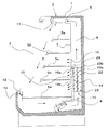
図1は本発明の実施の形態1に係るショーケースであるオープンショーケースの側面視の縦断面図であり、図中の矢印は空気の流れを示している。
The present invention will be described below with reference to illustrated embodiments.
FIG. 1 is a longitudinal sectional view in side view of an open showcase which is a showcase according to
本実施の形態のオープンショーケースは、図1のように前面に商品出し入れ用の開口2を有する本体3が、断熱壁1で形成された箱状を呈し、内部を商品を陳列し冷蔵保存する保存室4に構成されている。保存室4は、上下に複数の陳列棚5a〜5eを備え、天面パネル6、背面パネル7、及び最下段の陳列棚5eによって断熱壁1の内方に画成されており、これによって保存室4と断熱壁1との間に空気循環ダクト8が形成されるようになっている。空気循環ダクト8は、内部に送風機9と冷却器10が配置され、上端は空気吹出口11に連通し、下端は吸込口12に連通している。空気吹出口11は、吹出し気流の直進性を高めるためにハニカム構造となっている。なお、保存室4の両側開口は、本体3の断熱性を有する側壁(図示せず)にてそれぞれ覆われるようになっている。
In the open showcase of the present embodiment, as shown in FIG. 1, the
冷却器10は、冷媒が流れる伝熱管22の周囲に伝熱フィン23を固定した蒸気圧縮式ヒートポンプの蒸発器で構成されており、空気循環ダクト8内の鉛直部の下部に配置されている。伝熱管22は、上下方向に整列した配管群が前面側から背面側にかけて複数列(図では4列)並設されたものである。
The
冷却器10と背面パネル7の間には、補助風路13が設けられている。冷却器10と補助風路13は、冷却器前面を覆う冷却器仕切板14で画成されている。空気循環ダクト8内の冷却器10の上方(空気の流れの下流側)には、冷却器通過後の空気の流れを前面側の流れと背面側の流れとに分離して、前面側の流れの一部を補助風路13に誘導する円弧状の導風板24が設けられている。
An
背面パネル7における保存室4の高さ方向中央よりも下側の陳列棚5c,5d,5eに対応する部位には、複数の背面空気吹出し孔が設けられている。ここでは、特に冷却器10の上端よりも上方にある背面空気吹出し孔を上部背面孔15と呼び、それよりも下方にある背面空気吹出し孔を下部背面孔16a,16bと呼ぶことにする。
A plurality of back air blowing holes are provided in portions of the
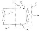
図2は本実施の形態のオープンショーケースで用いられる冷却器(蒸発器)10をヒートポンプの蒸発器とする冷凍装置の冷媒回路図であり、図中の矢印は冷媒の流れる向きを示している。冷却器(蒸発器)10は、図2のようにオープンショーケースの本体3とは別に設置された冷凍機17と冷媒配管21により接続されている。すなわち、冷凍機17は、圧縮機18、凝縮器19、及び膨張弁20が冷媒配管21によって直列に接続されて構成されており、膨張弁20と圧縮機18の間に冷却器(蒸発器)10が接続され、これらが閉ループに接続されるようになっている。
FIG. 2 is a refrigerant circuit diagram of a refrigeration apparatus in which the cooler (evaporator) 10 used in the open showcase of the present embodiment is an evaporator of a heat pump, and arrows in the figure indicate the direction of refrigerant flow. . As shown in FIG. 2, the cooler (evaporator) 10 is connected to a
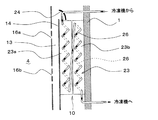
冷却器10内部の配管に冷媒が流れる順路を図3の模式図に示す。紙面垂直方向に冷却器10を貫く、上下で隣接する伝熱管22相互の両端は、エルボ状の連結管26で接続され、これによって直列に連なる千鳥配管が形成されるようになっている。図3中、実線で示す連結管26は、冷却器10の紙面手前側で接続していることを示し、破線で示す連結管26は、冷却器10の紙面奥側で接続していることを示している。また、矢印は、冷媒の流れる向きを示す。
A schematic diagram of FIG. 3 shows a route through which the refrigerant flows in the pipe inside the
すなわち、伝熱管22相互を直列につなぐ連結管26は、冷却器10を流れる冷媒が、補助風路13側(前面側)が入口側となり、断熱壁1側(背面側)が出口側となって流れるように配管されている。なお、伝熱フィン23は、冷媒流れの上流となる前面側と下流となる背面側との間、つまり二層冷媒が流れる伝熱管22側の第1の伝熱フィン23aとガス状冷媒が流れる伝熱管22側の第2の伝熱フィン23bとの間で、分割されている。
That is, in the connecting
次に、本実施の形態のオープンショーケースの冷却動作について説明する。
送風機9の作用により、保存室4内の空気が吸込口12から空気循環ダクト8に吸い込まれる。その際、保存室4内の空気だけでなく、本体3外部の空気(外気)も一部吸い込まれる。空気循環ダクト8に吸い込まれた空気は、送風機9から吹き出された後、冷却器10を通過する際に伝熱フィン23や伝熱管22と熱交換を行い温度が下がる。冷却器10を通過した低温の空気の多くは天面にある空気吹出口11から吹き出され、その他は上部背面孔15、下部背面孔16a,16bを介して保存室4に吹き出される。保存室4に吹き出された低温の空気は、保存室4を低温に保ち、陳列棚5a〜5eに置かれる商品を冷蔵保存する。
Next, the cooling operation of the open showcase of this embodiment will be described.
By the action of the blower 9, the air in the
蒸気圧縮式ヒートポンプの圧縮機18の周波数や膨張弁20の開度などの制御により、冷却器10に流入する冷媒は、当該冷却器10の入口側で気液二層状態となり、冷却器10の出口側でガス状、つまりガス単層に過熱された状態となる。例えば、保存室4を7℃に保つ場合には、冷却器10の入口側で二層冷媒温度はおよそ−10℃、冷却器10の出口側で加熱冷媒温度はおよそ0℃前後となる。
By controlling the frequency of the
本実施の形態のオープンショーケースは、冷却器10内部の冷媒がガス単層となり気液二層領域よりも高温となる伝熱管22が断熱壁1側である背面側に配管されるように設置しているので、冷却器10を通過する空気温度は、保存室4側である前面側が低く、背面側が高くなる分布を持つ。
The open showcase of the present embodiment is installed so that the refrigerant in the cooler 10 is a gas single layer and the temperature of the
上部背面孔15や下部背面孔16a,16bから保存室4へ吹出す空気は、冷却器10の前面側を通過した空気の比率が高いので、上部背面孔15や下部背面孔16a,16bから保存室4へ吹出す空気温度は従来のものよりも低くなる。
The air blown out from the
更に、冷却器10内の前面側を通過する低温の空気によって、冷却器前面の冷却器仕切板14の温度も下がり、伝熱により補助風路13内の空気から冷却器仕切板14への熱移動が高まり、補助風路13内の空気温度を下げて下部背面孔16a,16bからの吹き出し空気温度が下がる。
Further, the temperature of the
上部背面孔15や下部背面孔16a,16b、特に下部背面孔16a,16bは、保存室4の陳列棚の中でも高温になり易い最下段の陳列棚5eの開口2付近に近いので、下部背面孔16a,16bの吹出し空気温度を下げることにより、最下段の陳列棚5eの開口2付近の温度を下げ、保存室4内の温度分布を小さくすることができる。そのため、オープンショーケース全体の熱負荷が小さくなり、省エネ性能を高めることができる。
Since the
また、冷却器10の伝熱フィン23を、伝熱管22の温度が高くなる出口側がある背面側の第2の伝熱フィン23bと、それよりも伝熱管22の温度が低くなる前面側の第1の伝熱フィン23aとの間で分割しているので、背面側の伝熱管22からの伝熱で、前面側の第1の伝熱フィン23aの温度が高くなってしまうことを防ぐことができる。つまり、冷却器10の下流の温度分布が大きくなり、冷却器仕切板14側の冷却器通過空気温度が下がるため、上部背面孔15や下部背面孔16a,16bから保存室4に吹出す空気の温度をより下げることができ、保存室4の温度分布を小さくすることができて、熱負荷が低減し、省エネ性能向上の効果を高めることができる。
Further, the
また、空気循環ダクト8内の前記冷却器の上方(空気の流れの下流側)に、冷却器通過後の空気の流れを前面側の流れと背面側の流れとに分離して、前面側の流れの一部を補助風路13に誘導する円弧状の導風板24を備えているので、より低温の空気を効率的に補助風路13に導くことができる。このため、補助風路13内の空気温度が下がり、より冷たい空気を下部背面孔16a,16bから保存室4へ吹き出させることができる。これにより、保存室4内の温度分布を小さくすることができて、熱負荷が低減され、省エネ性能を向上させることができる。
Further, above the cooler in the air circulation duct 8 (downstream of the air flow), the air flow after passing the cooler is separated into a front side flow and a back side flow, Since the arc-shaped
ところで、オープンショーケースでは、前面が開放されているため、吸込口12から空気循環ダクト8に流入する空気の一部は温度が高く多くの水分を含む外気である。そのため、冷却器10の伝熱フィン23や伝熱管22への着霜が多く、霜により冷却器10の風路が閉塞して連続運転できなくなるという問題がある。
By the way, in the open showcase, since the front surface is opened, a part of the air flowing into the
本実施の形態のオープンショーケースは、前面側の伝熱管22および第1の伝熱フィン23aの温度を低くし、背面側の伝熱管22および第2の伝熱フィン23bの温度を前面側よりも高くしているので、霜は前面側の伝熱管22および第1の伝熱フィン23aに優先的に着いて、背面側への着霜は遅くなる。そのため、前面側が着霜により閉塞しても、着霜が遅い背面側が空気の流路となり、冷却器10の風路が完全に閉塞して連続運転できなくなるまでの時間を長くすることができる。よって、本実施の形態によればオープンショーケースの連続運転時間を長くすることができる。
In the open showcase of the present embodiment, the temperatures of the
また、前述のように前面側の伝熱管22および第1の伝熱フィン23aの温度を低くし、背面側の伝熱管22および第2の伝熱フィン23bの温度を前面側よりも高くすることで、冷却器10の位置に対応する断熱壁1からの熱侵入を小さくすることができ、熱負荷が低減されて省エネ性能を高めることができる。
Further, as described above, the temperatures of the
実施の形態2.
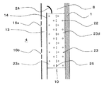
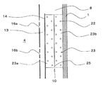
図4は本発明の実施の形態2に係るショーケースであるオープンショーケースの冷却器周りの拡大縦断面図であり、図中、前述の実施の形態1のものと同一機能部分には同一符号を付し、説明を省略する。なお、説明にあたっては、前述の図1及び図2を参照するものとする。
FIG. 4 is an enlarged vertical sectional view around the cooler of the open showcase which is the showcase according to the second embodiment of the present invention. In the figure, the same reference numerals are given to the same functional parts as those of the first embodiment described above. The description is omitted. In the description, reference is made to FIG. 1 and FIG.
本実施の形態のオープンショーケースは、図4のように冷却器10の伝熱フィン23の冷媒流れ上流となる前方側と下流となる背面側との間、つまり二層冷媒が流れる伝熱管22側の第1の伝熱フィン部23cとガス状冷媒が流れる伝熱管22側の第2の伝熱フィン部23dとの間に、これら第1と第2の伝熱フィン部23c,23d間での熱伝達を抑制するための複数のスリット25を上下方向に形成したものである。それ以外の構成は前述の実施の形態1のものと同様である。
As shown in FIG. 4, the open showcase of the present embodiment includes a
本実施の形態のオープンショーケースにおいても、蒸気圧縮式ヒートポンプの圧縮機18の周波数や膨張弁20の開度などの制御により、冷却器10に流入する冷媒は、当該冷却器10の入口側で気液二層状態となり、冷却器10の出口側でガス状、つまりガス単層に過熱された状態となる。そして、冷却器10内部の冷媒がガス単層となり気液二層領域よりも高温となる伝熱管22が断熱壁1側である背面側に配置されるように設置しているので、冷却器10を通過する空気温度は、保存室4側である前面側が低く、背面側が高くなる分布を持つ。
Also in the open showcase of the present embodiment, the refrigerant flowing into the cooler 10 is controlled at the inlet side of the cooler 10 by controlling the frequency of the
したがって、上部背面孔15や下部背面孔16a,16bから保存室4へ吹出す空気は、冷却器10内の前面側を通過した空気の比率が高くなり、上部背面孔15や下部背面孔16a,16bから保存室4へ吹出す空気温度は従来のものより低くなる。このため、最下段の陳列棚5eの開口2付近の温度を下げ、保存室4内の温度分布を小さくすることができ、オープンショーケース全体の熱負荷が小さくなり、省エネ性能を高めることができる。
Therefore, the ratio of the air that has passed through the front side in the cooler 10 is high in the air blown out from the
また、本実施の形態のオープンショーケースにおいても、空気循環ダクト8内の前記冷却器の上方(空気の流れの下流側)に、冷却器通過後の空気の流れを前面側の流れと背面側の流れとに分離して、前面側の流れの一部を補助風路13に誘導する円弧状の導風板24を備えているので、より低温の空気を効率的に補助風路13に導くことができる。このため、補助風路13内の空気温度が下がり、より冷たい空気を下部背面孔16a,16bから保存室4へ吹き出させることができる。これにより、保存室4内の温度分布を小さくすることができて、熱負荷が低減され、省エネ性能を向上させることができる。
Also in the open showcase of the present embodiment, the air flow after passing through the cooler is placed above the cooler in the air circulation duct 8 (on the downstream side of the air flow) and the front side flow and the back side. Since the arc-shaped
また、二層冷媒が流れる伝熱管22側の第1の伝熱フィン部23cとガス状冷媒が流れる伝熱管22側の第2の伝熱フィン部23dとの間に、これら第1と第2の伝熱フィン部23c,23d間での熱伝達を抑制するための複数のスリット25を上下方向に形成しているので、背面側の伝熱管22からの伝熱で、前面側の第1の伝熱フィン部23cの温度が高くなってしまうことを抑制することができ、省エネ性能向上の効果を高めることができる。
Further, between the first heat
また、既述したように、前面側の伝熱管22および第1の伝熱フィン部23cの温度を低くし、背面側の伝熱管22および第2の伝熱フィン部23dの温度を前面側よりも高くしているので、霜は前面側の伝熱管22および第1の伝熱フィン部23cに優先的に着いて、背面側への着霜は遅くなる。そのため、前面側が着霜により閉塞しても、着霜が遅い背面側が空気の流路となり、冷却器10の風路が完全に閉塞して連続運転できなくなるまでの時間を長くすることができ、連続運転時間を長くすることができる。
Further, as described above, the temperatures of the
なお、本実施の形態においては、第1と第2の伝熱フィン部23c,23d間に、熱伝達を抑制するための複数のスリット25を形成しているものの、これら第1と第2の伝熱フィン部23c,23dは分離されているわけではなく一体に構成されているので、前述の実施の形態1のものと比べて、冷却器10を通過する空気温度の分布を大きくする効果は弱まる。しかし、伝熱フィンの枚数が前述の分離方式のものと比べて半分以下の枚数で済むため、伝熱フィンの製造が容易になるという利点がある。
In the present embodiment, a plurality of
実施の形態3.
図5は本発明の実施の形態3に係るショーケースであるオープンショーケースの冷却器周りの拡大縦断面図であり、図中、前述の実施の形態1のものと同一機能部分には同一符号を付し、説明を省略する。なお、ここでも説明にあたっては、前述の図1及び図2を参照するものとする。
FIG. 5 is an enlarged vertical sectional view around the cooler of the open showcase which is the showcase according to the third embodiment of the present invention. In FIG. The description is omitted. In this case, the description will be made with reference to FIGS. 1 and 2 described above.
本実施の形態のオープンショーケースは、図5のように前述の実施の形態1のものから導風板24を省いたものであり、それ以外の構成は前述の実施の形態1のものと同様である。
The open showcase of the present embodiment is obtained by omitting the
本実施の形態のオープンショーケースにおいても、蒸気圧縮式ヒートポンプの圧縮機18の周波数や膨張弁20の開度などの制御により、冷却器10に流入する冷媒は、当該冷却器10の入口側で気液二層状態となり、冷却器10の出口側でガス状、つまりガス単層に過熱された状態となる。そして、冷却器10内部の冷媒がガス単層となり気液二層領域よりも高温となる伝熱管22が断熱壁1側である背面側に配置されるように設置しているので、冷却器10を通過する空気温度は、保存室4側である前面側が低く、背面側が高くなる分布を持つ。
Also in the open showcase of the present embodiment, the refrigerant flowing into the cooler 10 is controlled at the inlet side of the cooler 10 by controlling the frequency of the
したがって、上部背面孔15や下部背面孔16a,16bから保存室4へ吹出す空気は、冷却器10内の前面側を通過した空気の比率が高くなり、上部背面孔15や下部背面孔16a,16bから保存室4へ吹出す空気温度は従来のものよりも低くなる。このため、最下段の陳列棚5eの開口2付近の温度を下げ、保存室4内の温度分布を小さくすることができ、オープンショーケース全体の熱負荷が小さくなり、省エネ性能を高めることができる。
Therefore, the ratio of the air that has passed through the front side in the cooler 10 is high in the air blown out from the
また、既述したように、前面側の伝熱管22および第1の伝熱フィン23aの温度を低くし、背面側の伝熱管22および第2の伝熱フィン23bの温度を前面側よりも高くしているので、霜は前面側の伝熱管22および第1の伝熱フィン23aに優先的に着いて、背面側への着霜は遅くなる。そのため、前面側が着霜により閉塞しても、着霜が遅い背面側が空気の流路となり、冷却器10の風路が完全に閉塞して連続運転できなくなるまでの時間を長くすることができ、連続運転時間を長くすることができる。
Further, as described above, the temperatures of the
なお、本実施の形態のオープンショーケースは、前述の実施の形態1のものから導風板24を省いたものであるため、冷却器10内の前面側を通過して補助風路13に流入する空気の比率が前述の実施の形態1のものと比べて低くなり、下部背面孔16a,16bから保存室4へ吹出す空気の温度を低下させる効果は実施の形態1よりも弱くなる。しかし、導風板24を省いた分、部品点数を削減できるため、製造が容易となり、かつコストを低減することができるという利点がある。
Note that the open showcase of the present embodiment is obtained by omitting the
なお、前述の各実施の形態では、いずれもショーケースとしてオープンショーケースを例に挙げて説明したが、本発明はこれに限るものでなく、例えば前面がガラスで覆われていて、庫内を温度ムラなく保冷すべき、冷凍・冷蔵用のクローズドショーケースへの適用が可能である。 In each of the above-described embodiments, the open showcase has been described as an example of the showcase, but the present invention is not limited to this. For example, the front surface is covered with glass, and the interior is It can be applied to a closed showcase for freezing and refrigeration that should be kept cool without uneven temperature.
1 断熱壁、2 開口、3 ショーケース本体、4 保存室、5a〜5e 陳列棚、6 天面パネル、7 背面パネル、8 空気循環ダクト、9 送風機、10 冷却器(蒸発器)、11 空気吹出口、12 吸込口、13 補助風路、14 冷却器仕切板、15 上部背面孔(背面空気吹出し孔)、16a,16b 下部背面孔(背面空気吹出し孔)、17 冷凍機、18 圧縮機、19 凝縮器、20 膨張弁、21 冷媒配管、22 伝熱管、23 伝熱フィン、23a 第1の伝熱フィン、23b 第2の伝熱フィン、23c 第1の伝熱フィン部、23d 第2の伝熱フィン部、24 導風板、25 スリット、26 連結管。
DESCRIPTION OF
Claims (5)
前記保存室の周りを前記前面の開口を除いて覆う断熱壁で形成された箱状の本体と、
前記保存室と前記本体の断熱壁との間に形成された空気循環ダクトと、
ヒートポンプの蒸発器で構成され、前記空気循環ダクト内の前記背面パネルの背面側の下部位置に設置されて、伝熱管の内部に冷媒を循環させ、該伝熱管の周囲に伝熱フィンを保持した冷却器と、
前記保存室と前記冷却器との間で前記空気循環ダクトを通し空気を循環させる送風機と、
前記冷却器の前面を覆う冷却器仕切板と、
前記冷却器仕切板と前記背面パネルとの間に形成され、冷却器通過後の空気が導かれる補助風路と、
前記背面パネルに設けられ、前記補助風路から前記保存室へ空気を吹き出す背面吹出し孔とを備え、
前記冷却器は、
前記伝熱管が、前面側から背面側に複数列配置され、
内部を流れる冷媒が、入口側で二層状態となり、出口側でガス状に過熱した状態となるように制御され、二層状態の冷媒が流れる伝熱管が前面側に近い列に位置し、ガス状に加熱した状態となる冷媒が流れる伝熱管が背面側に近い列に位置するように配置されてなることを特徴とするショーケース。 A storage room having a rear panel on the back, a top panel on the top, a bottom shelf on the bottom, an open front, and a plurality of display shelves in the vertical direction;
A box-shaped main body formed of a heat insulating wall covering the storage chamber except for the opening on the front surface;
An air circulation duct formed between the storage chamber and the heat insulating wall of the main body;
Consists of a heat pump evaporator, installed at a lower position on the back side of the back panel in the air circulation duct, circulating a refrigerant inside the heat transfer tube, and holding heat transfer fins around the heat transfer tube A cooler,
A blower for circulating air through the air circulation duct between the storage chamber and the cooler;
A cooler partition plate covering the front surface of the cooler;
An auxiliary air passage formed between the cooler partition plate and the back panel, through which air after passing through the cooler is guided;
Provided on the back panel, and provided with a back blowing hole for blowing air from the auxiliary air passage to the storage chamber,
The cooler is
The heat transfer tubes are arranged in a plurality of rows from the front side to the back side,
The refrigerant flowing inside is controlled to be in a two-layer state on the inlet side and in a gas-like superheated state on the outlet side, and the heat transfer tubes through which the refrigerant in the two-layer state flows are located in a row near the front side, The showcase is characterized in that the heat transfer tubes through which the refrigerant that is heated in a shape flows are positioned in a row close to the back side.
圧縮機と、凝縮器と、膨張弁とを備え、
前記圧縮機と、前記凝縮器と、前記膨張弁と、前記ショーケースに搭載された冷却器とを、閉ループに配管接続してヒートポンプ回路を構成することを特徴とする冷凍装置。 The showcase according to any one of claims 1 to 4,
A compressor, a condenser, and an expansion valve;
A refrigerating apparatus comprising a heat pump circuit in which the compressor, the condenser, the expansion valve, and a cooler mounted on the showcase are connected in a closed loop.
Priority Applications (1)
| Application Number | Priority Date | Filing Date | Title |
|---|---|---|---|
| JP2010257891A JP5188564B2 (en) | 2010-11-18 | 2010-11-18 | Showcase and refrigeration equipment |
Applications Claiming Priority (1)
| Application Number | Priority Date | Filing Date | Title |
|---|---|---|---|
| JP2010257891A JP5188564B2 (en) | 2010-11-18 | 2010-11-18 | Showcase and refrigeration equipment |
Publications (2)
| Publication Number | Publication Date |
|---|---|
| JP2012105863A JP2012105863A (en) | 2012-06-07 |
| JP5188564B2 true JP5188564B2 (en) | 2013-04-24 |
Family
ID=46492180
Family Applications (1)
| Application Number | Title | Priority Date | Filing Date |
|---|---|---|---|
| JP2010257891A Active JP5188564B2 (en) | 2010-11-18 | 2010-11-18 | Showcase and refrigeration equipment |
Country Status (1)
| Country | Link |
|---|---|
| JP (1) | JP5188564B2 (en) |
Families Citing this family (4)
| Publication number | Priority date | Publication date | Assignee | Title |
|---|---|---|---|---|
| US10314411B2 (en) * | 2016-05-25 | 2019-06-11 | Hussmann Corporation | Refrigerated merchandiser with airflow support system |
| CN113303632A (en) * | 2021-06-29 | 2021-08-27 | 青岛海力商用电器有限公司 | Refrigeration display cabinet with good refrigeration effect |
| JP2024039792A (en) * | 2022-09-12 | 2024-03-25 | シャープ株式会社 | evaporator and refrigerator |
| DE102022130800A1 (en) * | 2022-11-22 | 2024-05-23 | Wanzl GmbH & Co. KGaA | Refrigeration cabinets and airflow cooling module |
Family Cites Families (5)
| Publication number | Priority date | Publication date | Assignee | Title |
|---|---|---|---|---|
| JPH0537186Y2 (en) * | 1988-11-24 | 1993-09-20 | ||
| JPH06265255A (en) * | 1993-03-12 | 1994-09-20 | Fuji Electric Co Ltd | Open showcase ventilation structure |
| JPH08303933A (en) * | 1995-05-08 | 1996-11-22 | Fuji Electric Co Ltd | Defroster for freezer refrigeration showcase |
| JP3003585B2 (en) * | 1996-08-12 | 2000-01-31 | 富士電機株式会社 | Refrigerated display case |
| JP2006207885A (en) * | 2005-01-26 | 2006-08-10 | Okamura Corp | Refrigerating open showcase |
-
2010
- 2010-11-18 JP JP2010257891A patent/JP5188564B2/en active Active
Also Published As
| Publication number | Publication date |
|---|---|
| JP2012105863A (en) | 2012-06-07 |
Similar Documents
| Publication | Publication Date | Title |
|---|---|---|
| KR101520704B1 (en) | Refrigerator | |
| CN101815910A (en) | freezer | |
| JP2008202823A (en) | refrigerator | |
| JP5847198B2 (en) | refrigerator | |
| JP5188564B2 (en) | Showcase and refrigeration equipment | |
| JP2014077615A (en) | Refrigerator | |
| KR102707771B1 (en) | Condenser and Refrigerator having the same | |
| JP4375312B2 (en) | Cold air circulation display case | |
| JP5405158B2 (en) | Evaporator | |
| JP5701572B2 (en) | CO2 brine cooling method and cooling equipment | |
| JP2014020736A (en) | Refrigerator | |
| JP2009174779A (en) | Showcase | |
| JP5139093B2 (en) | Cooling system | |
| JP2011247501A (en) | Cold air circulation type showcase | |
| JP7129372B2 (en) | refrigerator | |
| KR20200004216A (en) | Evaporator and refrigerator having the same | |
| WO2019175965A1 (en) | Refrigerator | |
| CN210035945U (en) | Refrigerator with evaporator with bending structure | |
| JP5367553B2 (en) | Cooling storage | |
| JP2010071540A (en) | Showcase | |
| JP3919597B2 (en) | refrigerator | |
| JP6145640B2 (en) | refrigerator | |
| JP7759536B2 (en) | refrigerator | |
| KR100374169B1 (en) | Refrigerator with improved air circulation efficiency | |
| JP5553101B2 (en) | Cooler and cooler |
Legal Events
| Date | Code | Title | Description |
|---|---|---|---|
| TRDD | Decision of grant or rejection written | ||
| A01 | Written decision to grant a patent or to grant a registration (utility model) |
Free format text: JAPANESE INTERMEDIATE CODE: A01 Effective date: 20121225 |
|
| A61 | First payment of annual fees (during grant procedure) |
Free format text: JAPANESE INTERMEDIATE CODE: A61 Effective date: 20130122 |
|
| FPAY | Renewal fee payment (event date is renewal date of database) |
Free format text: PAYMENT UNTIL: 20160201 Year of fee payment: 3 |
|
| R150 | Certificate of patent or registration of utility model |
Ref document number: 5188564 Country of ref document: JP Free format text: JAPANESE INTERMEDIATE CODE: R150 Free format text: JAPANESE INTERMEDIATE CODE: R150 |
|
| R250 | Receipt of annual fees |
Free format text: JAPANESE INTERMEDIATE CODE: R250 |
|
| R250 | Receipt of annual fees |
Free format text: JAPANESE INTERMEDIATE CODE: R250 |
|
| R250 | Receipt of annual fees |
Free format text: JAPANESE INTERMEDIATE CODE: R250 |
|
| R250 | Receipt of annual fees |
Free format text: JAPANESE INTERMEDIATE CODE: R250 |
|
| R250 | Receipt of annual fees |
Free format text: JAPANESE INTERMEDIATE CODE: R250 |
|
| R250 | Receipt of annual fees |
Free format text: JAPANESE INTERMEDIATE CODE: R250 |
|
| R250 | Receipt of annual fees |
Free format text: JAPANESE INTERMEDIATE CODE: R250 |
|
| R250 | Receipt of annual fees |
Free format text: JAPANESE INTERMEDIATE CODE: R250 |
|
| R250 | Receipt of annual fees |
Free format text: JAPANESE INTERMEDIATE CODE: R250 |
|
| R250 | Receipt of annual fees |
Free format text: JAPANESE INTERMEDIATE CODE: R250 |
|
| R250 | Receipt of annual fees |
Free format text: JAPANESE INTERMEDIATE CODE: R250 |