JP5367553B2 - Cooling storage - Google Patents
Cooling storage Download PDFInfo
- Publication number
- JP5367553B2 JP5367553B2 JP2009285282A JP2009285282A JP5367553B2 JP 5367553 B2 JP5367553 B2 JP 5367553B2 JP 2009285282 A JP2009285282 A JP 2009285282A JP 2009285282 A JP2009285282 A JP 2009285282A JP 5367553 B2 JP5367553 B2 JP 5367553B2
- Authority
- JP
- Japan
- Prior art keywords
- evaporator
- closing plate
- stretched
- gap
- air
- Prior art date
- Legal status (The legal status is an assumption and is not a legal conclusion. Google has not performed a legal analysis and makes no representation as to the accuracy of the status listed.)
- Expired - Fee Related
Links
- 238000001816 cooling Methods 0.000 title claims description 35
- 238000003860 storage Methods 0.000 title claims description 17
- 229910052751 metal Inorganic materials 0.000 claims description 6
- 239000002184 metal Substances 0.000 claims description 6
- 238000007664 blowing Methods 0.000 claims 1
- 230000015572 biosynthetic process Effects 0.000 description 17
- 238000003780 insertion Methods 0.000 description 10
- 230000037431 insertion Effects 0.000 description 10
- 238000005057 refrigeration Methods 0.000 description 8
- 238000001704 evaporation Methods 0.000 description 7
- 229910052782 aluminium Inorganic materials 0.000 description 5
- XAGFODPZIPBFFR-UHFFFAOYSA-N aluminium Chemical compound [Al] XAGFODPZIPBFFR-UHFFFAOYSA-N 0.000 description 5
- 230000008020 evaporation Effects 0.000 description 3
- 239000003507 refrigerant Substances 0.000 description 3
- 229920003002 synthetic resin Polymers 0.000 description 3
- 239000000057 synthetic resin Substances 0.000 description 3
- 230000000694 effects Effects 0.000 description 2
- 239000006260 foam Substances 0.000 description 2
- 238000009434 installation Methods 0.000 description 2
- JOYRKODLDBILNP-UHFFFAOYSA-N Ethyl urethane Chemical compound CCOC(N)=O JOYRKODLDBILNP-UHFFFAOYSA-N 0.000 description 1
- 230000000593 degrading effect Effects 0.000 description 1
- 239000011810 insulating material Substances 0.000 description 1
- 238000009413 insulation Methods 0.000 description 1
- 230000014759 maintenance of location Effects 0.000 description 1
- 239000000463 material Substances 0.000 description 1
- 238000012856 packing Methods 0.000 description 1
- 230000000149 penetrating effect Effects 0.000 description 1
- 229920005989 resin Polymers 0.000 description 1
- 239000011347 resin Substances 0.000 description 1
- 238000010257 thawing Methods 0.000 description 1
- XLYOFNOQVPJJNP-UHFFFAOYSA-N water Substances O XLYOFNOQVPJJNP-UHFFFAOYSA-N 0.000 description 1
Images

Landscapes
- Cold Air Circulating Systems And Constructional Details In Refrigerators (AREA)
Description
本発明は冷却貯蔵庫に関し、特に蒸発器室に収容された蒸発器周辺の構造の改良に関する。 The present invention relates to a cooling storage, and more particularly to an improvement in the structure around an evaporator housed in an evaporator chamber.
庫内の天井部に蒸発器を備えた形式の冷蔵庫の一例として、特許文献1に記載されたものが知られている。このものは、断熱箱からなる冷蔵庫本体の天井部に、ドレンパンを兼ねたダクトが張られることで蒸発器室が区画形成され、同蒸発器室の天井壁の上面に冷凍装置が設置される一方、天井壁の下面側に、蒸発器がドレンパンに倣った斜め姿勢の吊り下げ状態で収容される。そして、ダクトにおける扉側に設けられた吸込口に装備された冷却ファンが駆動されると、庫内空気が同吸込口から蒸発器室に吸い込まれ、蒸発器を通過する間に生成された冷気がダクトの奥側に設けられた吹出口から吹き出されて庫内に循環供給されることで庫内が冷却されるようになっている。 What was described in patent document 1 is known as an example of the refrigerator of the type provided with the evaporator in the ceiling part in a store | warehouse | chamber. In this case, an evaporator room is defined by a duct that also serves as a drain pan is stretched on the ceiling of the refrigerator body made of a heat insulation box, and a refrigeration system is installed on the upper surface of the ceiling wall of the evaporator room. The evaporator is housed on the lower surface side of the ceiling wall in a slanting suspended state following the drain pan. And when the cooling fan equipped in the suction port provided on the door side in the duct is driven, the cool air generated while the internal air is sucked into the evaporator chamber from the suction port and passes through the evaporator Is blown out from the outlet provided on the back side of the duct and is circulated and supplied to the inside of the box to cool the inside.
ここで上記従来技術では、蒸発器をドレンパンの傾斜に倣った斜め姿勢で収容しているが故に、蒸発器の上面と天井壁の下面との間に所定の間隙が形成されることになるが、この間隙は冷却能力を維持する上で有効である。
例えば、多湿の条件下で扉開閉が頻繁に行われると、蒸発器の特に吸込側の面に多量の霜が付着して埋まり、吸い込んだ庫内空気の流通を妨げるおそれがあるが、そうなった場合でも、吸い込んだ庫内空気を上記の間隙に流通させて熱交換を図ることで冷却能力を維持し、ひいては冷凍装置の稼働時間を短縮して消費電力を抑えることが可能となる。
Here, in the above prior art, since the evaporator is accommodated in an inclined posture following the inclination of the drain pan, a predetermined gap is formed between the upper surface of the evaporator and the lower surface of the ceiling wall. This gap is effective in maintaining the cooling capacity.
For example, if the door is frequently opened and closed under humid conditions, a large amount of frost may adhere to the surface of the evaporator, particularly on the suction side, and this may hinder the flow of the air in the warehouse. Even in such a case, it is possible to maintain the cooling capacity by circulating the sucked air in the gap to exchange heat, thereby reducing the operating time of the refrigeration apparatus and reducing the power consumption.
しかしながら上記構造のものでは、霜の付着量が少なくて蒸発器内を庫内空気が流通し得る状態にある場合でも、蒸発器内の上部に入った庫内空気は、間隙側に逃げて流通し勝ちとなり、間隙を流通する場合は蒸発器内を流通する場合と比べれば熱交換の能力は劣ると言えるから、図らずも不必要に冷却能力の低下を招いてしまうという問題があった。
本発明は上記のような事情に基づいて完成されたものであって、その目的は、庫内空気を蒸発器との間で効率良く熱交換できるようにするところにある。
However, in the above structure, even when the amount of frost attached is small and the inside air can flow through the evaporator, the inside air entering the upper part of the evaporator escapes to the gap side and flows. However, since it can be said that the heat exchange capacity is inferior when the gap is circulated as compared with the case where the gap is circulated in the evaporator, the cooling capacity is unnecessarily reduced.
The present invention has been completed based on the above circumstances, and an object of the present invention is to enable efficient heat exchange between the air in the cabinet and the evaporator.
本発明は、断熱箱からなる貯蔵庫本体の天井部にはダクトが張られることで蒸発器室が区画形成され、同蒸発器室内に蒸発器が天井面との間に間隙を設けた形態で収容され、冷却ファンの駆動により庫内空気が前記ダクトの一側に設けられた吸込口から蒸発器室に吸い込まれ、前記蒸発器を通過する間に生成された冷気が前記ダクトの他側に設けられた吹出口から吹き出されて庫内に循環供給されることで冷却される冷却貯蔵庫において、前記蒸発器の上面には閉鎖板が張られており、かつ同閉鎖板は当該蒸発器の吸込端側の上面を開放した形態で張られているところに特徴を有する。 In the present invention, an evaporator chamber is defined by a duct being stretched on the ceiling portion of a storage body consisting of a heat insulating box, and the evaporator is accommodated in a form in which a gap is provided between the ceiling surface and the evaporator chamber. The cooler fan is driven to suck the air in the cabinet from the suction port provided on one side of the duct into the evaporator chamber, and the cool air generated while passing through the evaporator is provided on the other side of the duct. In a cooling storage that is cooled by being blown out from the blown outlet and circulated and supplied into the warehouse, a closing plate is stretched on the upper surface of the evaporator, and the closing plate is a suction end of the evaporator It is characterized in that it is stretched with the upper surface of the side open.
上記構成によれば、蒸発器への着霜量が少ないときは、蒸発器に導入された庫内空気は閉鎖板で遮られて間隙へ逃げることなく極力蒸発器内を流通し、効率良く熱交換される。着霜量が多くなって蒸発器内が埋められるようになったら、吸引された庫内空気は、比較的着霜のタイミングが遅い蒸発器の吸込端側の上面から間隙を流通し、相応の熱交換機能が維持される。
着霜量が少ないときにも不必要に冷却能力の低下を招くことなく、着霜量が多くなった場合の冷却能力の維持を図ることができる。
According to the above configuration, when the amount of frost formation on the evaporator is small, the air in the chamber introduced into the evaporator is blocked by the closing plate and circulates in the evaporator as much as possible without escaping to the gap, and heat is efficiently generated. Exchanged. When the amount of frost formation increases and the inside of the evaporator is filled, the sucked air in the cabinet flows through the gap from the upper surface on the suction end side of the evaporator, which has a relatively slow frost formation timing. The heat exchange function is maintained.
Even when the amount of frost formation is small, it is possible to maintain the cooling capacity when the amount of frost formation increases without unnecessarily degrading the cooling capacity.
また、以下のような構成としてもよい。
(1)前記閉鎖板は、前記蒸発器の吸込端側と対応する端縁が吹出端側に所定寸法後退して張られることにより、前記蒸発器の吸込端側の上面が開放されている。閉鎖板の吸込端側の端縁をずらして張るだけの簡単な構造で以て、間隙への流通路が確保される。
The following configuration may also be used.
(1) The closing plate has an end corresponding to the suction end side of the evaporator retracted by a predetermined dimension toward the blow-out end side, whereby the upper surface on the suction end side of the evaporator is opened. A flow path to the gap is ensured with a simple structure in which the end edge of the closing plate on the suction end side is shifted and stretched.
(2)前記閉鎖板は、前記蒸発器の上面全面に亘って張られており、かつ前記蒸発器の吸込端側と対応する端部には複数の開口が形成されることにより、前記蒸発器の吸込端側の上面が開放されている。着霜量が多くなった場合、庫内空気は閉鎖板における吸込端側に形成された開口を通って間隙を流通し、熱交換機能が維持される。 (2) The closing plate is stretched over the entire upper surface of the evaporator, and a plurality of openings are formed at an end corresponding to the suction end side of the evaporator, whereby the evaporator The upper surface on the suction end side is open. When the amount of frost formation increases, the internal air flows through the gap through the opening formed on the suction end side of the closing plate, and the heat exchange function is maintained.
(3)前記閉鎖板が金属製である。閉鎖板が熱伝導率が高い金属製であって閉鎖板自体が冷却されやすいから、閉鎖板と天井面との間隙を庫内空気が流通される場合に、より有効に熱交換される。 (3) The closing plate is made of metal. Since the closing plate is made of a metal having a high thermal conductivity and the closing plate itself is easily cooled, heat is more effectively exchanged when the internal air flows through the gap between the closing plate and the ceiling surface.
さらに本発明は、断熱箱からなる貯蔵庫本体の天井部にはダクトが張られることで蒸発器室が区画形成されて、同蒸発器室の天井面に蒸発器が設けられ、冷却ファンの駆動により庫内空気が前記ダクトの一側に設けられた吸込口から蒸発器室に吸い込まれ、前記蒸発器を通過する間に生成された冷気が前記ダクトの他側に設けられた吹出口から吹き出されて庫内に循環供給されることで冷却される冷却貯蔵庫において、前記蒸発器が、空気流通方向に沿った姿勢で同空気流通方向と交差する方向に間隔を開けて並べられた複数枚のフィンからなるフィン群を備える一方、このフィン群の上部側を除いた領域に対して蒸発管が各フィンを貫通しつつ複数段に亘って配管された構造となっているところに特徴を有する。 Further, according to the present invention, an evaporator chamber is defined by a duct being stretched on a ceiling portion of a storage body consisting of a heat insulating box, and an evaporator is provided on the ceiling surface of the evaporator chamber. The air in the cabinet is sucked into the evaporator chamber from the suction port provided on one side of the duct, and the cold air generated while passing through the evaporator is blown out from the air outlet provided on the other side of the duct. In the cooling storage that is cooled by being circulated and supplied into the storage, the evaporator is a plurality of fins arranged at intervals in a direction crossing the air flow direction in a posture along the air flow direction While the fin group which consists of this is provided, it has the characteristic in that it has the structure where the evaporating pipe is piped over a plurality of stages while penetrating each fin with respect to the region excluding the upper side of the fin group.
上記構成によれば、蒸発器と天井面との間隙が、蒸発器を構成するフィン群の上部側で埋められた状態となり、蒸発器への着霜量が少ないときは、熱交換面積が増加することとなって効率良く熱交換される。一方、着霜量が増えた場合も、フィン群の上部側には蒸発管が配管されていないことで未着霜空間が多く残り、すなわち庫内空気の流通空間が確保されて相応の熱交換機能が維持される。 According to the above configuration, the gap between the evaporator and the ceiling surface is filled with the upper side of the fin group constituting the evaporator, and the heat exchange area increases when the amount of frost formation on the evaporator is small. As a result, heat is exchanged efficiently. On the other hand, even when the amount of frost formation increases, there is not much frost formation space left on the upper side of the fin group because no evaporating pipes are installed, that is, a distribution space for the internal air is secured, and the corresponding heat exchange is achieved. Function is maintained.
ここで、前記蒸発器を構成する各フィンの吸込側の端縁の位置が、空気流通方向に沿った前後方向において交互にずれている構成としてもよい。各フィンの吸込側の端縁に霜が付いた場合、端縁位置が交互に前後にずれていることで、蒸発器における吸込側の端面の全面が早期に埋まることが回避され、比較的長時間に亘って庫内空気が蒸発器内を流通することが担保される。 Here, it is good also as a structure which the position of the edge by the side of suction of each fin which comprises the said evaporator has shifted | deviated alternately in the front-back direction along an air circulation direction. When frost is formed on the suction side edge of each fin, the edge position is alternately shifted back and forth, so that the entire suction side end face of the evaporator is prevented from being filled early, and is relatively long. It is ensured that the in-compartment air flows through the evaporator over time.
本発明によれば、庫内空気を蒸発器との間で効率良く熱交換することができ、ひいては消費電力を抑えることが可能となる。 According to the present invention, it is possible to efficiently exchange heat between the internal air and the evaporator, and it is possible to suppress power consumption.
以下、本発明の実施形態を添付図面に基づいて説明する。
<実施形態1>
本発明の実施形態1を図1ないし図4によって説明する。本実施形態では、業務用の縦型冷蔵庫を例示している。
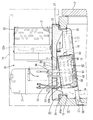
図1において、符号10は、前面の開口された断熱箱体からなる冷蔵庫本体であって、内部が冷蔵室11とされているとともに、冷蔵室11の前面開口には断熱扉12が揺動開閉可能に装着されている。冷蔵庫本体10の上面には、回りにパネルが立てられることで機械室14が構成されている。
Hereinafter, embodiments of the present invention will be described with reference to the accompanying drawings.
<Embodiment 1>
A first embodiment of the present invention will be described with reference to FIGS. In this embodiment, the vertical refrigerator for business is illustrated.
In FIG. 1,
機械室14の底面となる冷蔵庫本体10の天井壁10Aのほぼ中央部には、方形の開口部15が形成され、この開口部15の上面を塞ぐようにして、後記する冷凍装置30と蒸発器40等を搭載してユニット化するユニット台20が載置されている。
開口部15の前方側(図1の右側)における下面の口縁の位置から奥壁に向かい、ドレンパンを兼ねた冷却ダクト16が下り勾配で張設されており、ユニット台20との間に蒸発器室50が形成されている。冷却ダクト16の前端側には吸込口17が形成され、その裏面に冷却ファン18が装備されているとともに、冷却ダクト16の後端側には吹出口19が形成されている。
A
A
ユニット台20は断熱性であって、図2にも示すように、金属製の外装板21と合成樹脂製の内装板22とが上下に組み付けられ、間に発泡ウレタン樹脂等の発泡合成樹脂からなる断熱材23が充填された構造となっており、全体として、上記した開口部15よりも一回り大きい平面方形状に形成されている。
ユニット台20の下面には、上記した開口部15内に嵌合される方形状の突壁24が周設され、同突壁24の内側における後部側(図2の上側)の領域が、蒸発器40の取付領域25となっている。この取付領域25の左右両側縁に沿った位置には、前後一対ずつの取付用のボス26A,26Bが形成されている。各組のボス26A,26Bでは、前側(図1の右側)のボス26Aと比べて後側のボス26Bの方が、前後方向の長さが短い反面背が高く形成され、かつ各ボス26A,26Bの頂面である取付面27が、後方に向けて下り勾配となった一連の傾斜状に形成されている。前側のボス26Aの取付面27には選択的に用いられる2個のねじ孔28が、また後側のボス26Bの取付面27には1個のねじ孔28が形成されている。
The
A square-
ユニット台20の上面には冷凍装置30が搭載され、例えば図1に示すように、奥側に圧縮機31が、その前方に、凝縮器32と凝縮器ファン32Aとが前後に並んで取り付けられる。
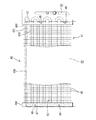
ユニット台20の下面には蒸発器40が取り付けられる。蒸発器40は全体としては、やや扁平で左右方向に細長いブロック状に形成される。より詳細には、図3にも示すように、前後方向に長い長方形の金属プレートからなるフィン42が、複数枚(数十枚)、一定間隔を開けて左右方向に並べられることによって、やや扁平で左右方向に細長いブロック状をなすフィン群41が形成される。フィン42はさらに、長さが長いフィン42Lと、短いフィン42Sの2種類が備えられ、各フィン42L,42Sが交互に配されるとともに、各フィン42L,42Sの後端(同図の下側)が揃えられる一方、前端は、長い方のフィン42Lが短い方のフィン42Sより所定寸法突出した形態となっている。なお以下では、長い方と短い方とを区別する必要があるとき以外は、両フィン42L,42Sを、フィン42とまとめて表記する。
上記したフィン群41には、冷媒配管44の一部を構成する蒸発管45が、各フィン42を貫通しつつ左右方向の蛇行を上下4段に亘って繰り返して配管されている。また、フィン群41の左右両端面には、それぞれエンドプレート46X,46Yが配されている。両エンドプレート46の上面板47には、それぞれ前後2個ずつのねじ48の挿通孔49が形成されている。
A
An
In the
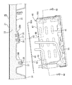
このような構造の蒸発器40が、図4に示すように後下がりの姿勢とされ、左右のエンドプレート46X,46Yの上面板47が、左右のボス26A,26Bの組に当てられる。そして、各上面板47に開口された挿通孔49にねじ48を通し、対応するボス26A,26Bの取付面27のねじ孔28にねじ込むことで固定される。蒸発器40に出し入れされる冷媒配管44が、図1に示すように、ユニット台20の貫通孔35を通して上面側に引き出され、冷凍装置30側の冷媒配管44と接続されて周知の冷凍サイクルが形成される。
As shown in FIG. 4, the
このように、冷凍装置30並びに蒸発器40等を取り付けたユニット台20が、所定の向きで開口部15を塞ぐようにしてその上面に載置される。具体的には、ユニット台20の下面の突壁24が開口部15の内側に嵌合されるとともに、ユニット台20の下面の周縁が、パッキン37を介して開口部15の表面側の口縁部に載置され、ユニット台20の下面の左右の側縁に突設された取付板36が、天井壁10Aの上面にねじで止められて固定される。これにより、上記したようにユニット台20と冷却ダクト16との間に、外気とは断熱された蒸発器室50が構成される。
As described above, the
ここで、ユニット台20の下面に取り付けられた蒸発器40は、上記のように後下がりの姿勢を採って、冷却ダクト16から若干浮いた状態で蒸発器室50内に収容される。それとともに、ユニット台20の下面における蒸発器40の取付領域25の天井面25Aと蒸発器40の上面との間には、所定の間隙53が形成される。この間隙53は、天井面25Aが水平面であるのに対して、蒸発器40の上面が後下がりの傾斜面であることから、前端側で狭く、後端に向けて次第に上下方向に広がる形態で形成されている。
Here, the
なお、蒸発器40等に付着した霜を除去するために、適宜に除霜運転が行われようになっており、そのため蒸発器40にはシーズヒータからなる除霜ヒータ55が装備され、例えば、図1に示すように、フィン群41の下面に形成された装着溝に嵌められて蛇行状に配管されている。
また、冷却ダクト16の下縁からは、同冷却ダクト16で受けた除霜水を排水するべく排水管57が突設されて、冷蔵庫本体10の奥壁に形成された排水路58に臨んでいる。
In addition, in order to remove the frost adhering to the
Further, a
さて、蒸発器40の上面には閉鎖板60が張られている。この閉鎖板60は、熱伝導性に優れたアルミニウム板製であって、図3の鎖線に示すように、両エンドプレート46X,46Yの上面板47を含めて蒸発器40の上面の全面に亘る大きさの平面長方形に形成されている。但し、同閉鎖板60は、その前縁60Aが、蒸発器40の上面における吸込端である前縁よりも所定寸法後退した位置に来るような形態で張られるようになっている。後退寸法は、例えば蒸発器40の上面の奥行の5〜10%程度である。
閉鎖板60の左右両側縁部には、同閉鎖板60が所定寸法後退して配された場合における、蒸発器40の両エンドプレート46X,46Yの取付板36の挿通孔49と整合する位置に、前後2個ずつのねじ48の挿通孔62が開口されている。
Now, a
The left and right side edges of the
そして閉鎖板60は、図4に示すように、蒸発器40をユニット台20の下面に取り付ける前において、両側縁部の挿通孔62を蒸発器40の左右のエンドプレート46X,46Yの挿通孔49と整合させた状態で蒸発器40の上面に載せられ、そののち左右のエンドプレート46X,46Yの上面板47が閉鎖板60の両側縁部を挟んだ状態で左右のボス26A,26Bの組に当てられ、各上面板47に開口された挿通孔49とこれと整合した閉鎖板60の挿通孔62にねじ48を通して、対応するボス26A,26Bの取付面27のねじ孔28にねじ込むことにより、すなわち共締めされて固定される。
これにより閉鎖板60は、後方に所定寸法ずれて蒸発器40の上面に張られた状態となり、言い換えると、蒸発器40の上面の吸込端側の所定寸法の範囲が、天井面52との間隙53に開放された状態となる。
As shown in FIG. 4, before the
As a result, the closing
続いて、本実施形態の作用を説明する。
冷却運転は、冷凍装置30(圧縮機31)と冷却ファン18とを駆動することで行われ、図1の矢線Aに示すように、冷蔵室11の庫内空気が冷却ファン18によって吸込口17から蒸発器室50内に吸引され、その空気が蒸発器40を前面側から流通する間に熱交換によって冷気が生成され、その冷気が吹出口19から冷蔵室11の奥面に沿うようにして吹き出され、冷蔵室11内に冷気が循環供給されることで冷却される。この間、蒸発器室50内における庫内空気の吸込口17側に配された庫内サーミスタ59によって庫内温度が検知され、その検知温度に基づいて圧縮機31の運転が制御されることにより、庫内が所定の冷蔵温度に維持されるようになっている。
Then, the effect | action of this embodiment is demonstrated.
The cooling operation is performed by driving the refrigeration apparatus 30 (compressor 31) and the cooling
一方その間、特に当該冷蔵庫の設置箇所が多湿雰囲気にあって断熱扉12の開閉が頻繁に行われたような場合には、蒸発器40の特に前面(吸込側の面)に次第に着霜し、次の除霜運転が行われる前に同前面が埋められる程に多量に着霜することがあり得る。なお、蒸発器40の前面に着霜する場合、下部側から次第に着霜することが経験上知られている。
On the other hand, especially when the installation location of the refrigerator is in a humid atmosphere and the
そこで本実施形態では、蒸発器40の上面に閉鎖板60が張られ、特に後方にずれて蒸発器40の上面の吸込端側(前面側)の所定寸法範囲が開放された状態で張られている。そのため、蒸発器40への着霜量が未だ少ない場合は、吸引された庫内空気が前面から蒸発器40内に導入され、同庫内空気は閉鎖板60で遮られて間隙53へ逃げることなく極力蒸発器40内を流通し、冷却状態にあるフィン42や蒸発管45と効率良く熱交換される。
着霜量が次第に多くなって蒸発器40の特に前面が埋められて来ると、庫内空気の蒸発器40内への導入が次第に制限されるようになるが、それでも図1の矢線aに示すように、庫内空気は比較的着霜のタイミングが遅い蒸発器40の前面の上端部から流入し、この部分は上面が開放されているから引き続いて間隙53を流通し、庫内空気の流通量がある程度確保される。ここで、閉鎖板60は熱伝導性に優れたアルミニウム板製であって、冷却状態にあるから、間隙53を流通する庫内空気も、蒸発器40内ほどではないにしても相応の熱交換機能が維持され、結果、冷却能力の低下が極力回避される。
Therefore, in the present embodiment, the closing
When the amount of frost formation gradually increases and especially the front surface of the
このように本実施形態によれば、着霜量が少ないときには、庫内空気が間隙53に逃げることを極力抑えて不必要に冷却能力の低下を招くことなく、着霜量が多くなった場合には、庫内空気の間隙53への流通を促して流通量を確保し、冷却能力の維持を図ることができる。
また、間隙53への流通路の確保については、閉鎖板60の前縁(吸込側の端縁)をずらして張るだけの簡単な構造で達成しており、ひいては安価に対応できる。
閉鎖板60が熱伝導率が高いアルミニウム板製であって閉鎖板60自体が冷却されやすいから、閉鎖板60と天井面52との間隙53を庫内空気が流通される場合に、より有効に熱交換される。
As described above, according to the present embodiment, when the amount of frost formation is small, the amount of frost formation is increased without suppressing the escape of the internal air to the
In addition, securing of the flow path to the
Since the
<実施形態2>
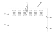
次に、本発明の実施形態2を図5及び図6によって説明する。この実施形態2では、閉鎖板65の形状並びに張設形態に変更が加えられている。
この実施形態2の閉鎖板65は、図6に示すように、上記実施形態1と同様にアルミニウム板を素材として、両エンドプレート46X,46Yの上面板47を含めて蒸発器40の上面の全面に亘る大きさの平面長方形に形成されている。この閉鎖板65は、蒸発器40の上面の全面を覆って張られるようになっており、そのため、同閉鎖板65の左右両側縁部には、同閉鎖板65が蒸発器40の上面全面を覆って配された場合における、蒸発器40の両エンドプレート46X,46Yの上面板47の挿通孔49と整合する位置に、前後2個ずつのねじ48の挿通孔62が開口されている。
そして、閉鎖板65の前縁側(吸込端側)における奥行の1/3強の長さ領域には、幅広のスリット状をなす複数の開口67が、整列して形成されている。
<Embodiment 2>
Next, a second embodiment of the present invention will be described with reference to FIGS. In the second embodiment, the shape of the
As shown in FIG. 6, the closing
A plurality of
閉鎖板65は、蒸発器40の上面全面を覆って載せられ、実施形態1と同様に、蒸発器40の左右のエンドプレート46X,46Yの上面板47が、天井面52に設けられた左右のボス26A,26Bの組に当てられてねじ48で止められることに伴い、共締めされて固定される。
これにより図5に示すように、蒸発器40の上面全面が閉鎖板65で覆われ、かつ前縁側の開口67の形成領域が、蒸発器40の上面における前縁側を覆った形態となる。
The closing
As a result, as shown in FIG. 5, the entire upper surface of the
この実施形態では、蒸発器40への着霜量が未だ少ない場合は、吸引された庫内空気が、図5の矢線Aに示すように、前面から蒸発器40内に導入され、同庫内空気は閉鎖板65で遮られて間隙53へ逃げることが極力抑えられつつ蒸発器40内を流通し、効率良く熱交換される。
着霜量が次第に多くなって蒸発器40の特に前面が埋められて来ると、同図の矢線bに示すように、庫内空気は比較的着霜のタイミングが遅い蒸発器40の前面の上端部から流入して、閉鎖板65の前縁側に設けられた開口67を通って間隙53に流通する。これにより、上記実施形態1と同様に、庫内空気の流通量がある程度確保された上で、相応の熱交換機能が維持され、冷却能力の低下が極力回避されるところとなる。
In this embodiment, when the amount of frost formation on the
When the amount of frost formation is gradually increased and the front surface of the
<実施形態3>
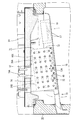
図7は、本発明の実施形態3を示す。この実施形態3では、蒸発器70の構造に変更が加えられている。
実施形態3の蒸発器70の上記した実施形態1に示した蒸発器40との相違点は、フィン群71を構成する各フィン72の形状が、元の長方形部73の上縁から、実施形態1に例示した蒸発器40の上面と天井面52との間隙53に倣った略三角形状の延出部74を延ばした形状となっている。蒸発管45は、フィン群71のうち長方形部73と対応する領域73Aにおいてのみ配管され、延出部74と対応する領域74Aには配管されていない。
その他、左右のエンドプレート46X,46Yの形状、各フィン72の前縁の位置が交互に前後方向にずれていること等については、上記実施形態1と同様である。
<Embodiment 3>
FIG. 7 shows Embodiment 3 of the present invention. In the third embodiment, the structure of the
The difference between the
In addition, the shapes of the left and
このような構造の蒸発器70が、同様にユニット台20の下面に取り付けられる。蒸発器70は後下がりの姿勢とされ、左右のエンドプレート46X,46Yの上面板47が左右のボス26A,26Bの組に当てられ、同様にねじ48で止められて固定される。このとき、各フィン72の延出部74の上縁、すなわちフィン群71における延出部74に対応する領域74Aの上面は水平姿勢となって、天井面52に当てられるようになっている。
言い換えると、本実施形態では、実施形態1に示した直方体のブロック状をなす蒸発器40を斜め姿勢で装備した場合に天井面52との間にできるであろう間隙53が、蒸発器70を構成するフィン群71における延出部74の領域74Aで埋められた状態となる。
The
In other words, in this embodiment, the
実施形態3の作用は以下のようである。蒸発器70への着霜量が少ない場合は、庫内空気は主に、フィン群71における長方形部73の領域73Aに流通し、さらにその一部は、実施形態1に示した間隙に相当する延出部74の領域74Aにも流通する。この延出部74の領域74Aは、蒸発管45こそ配管されてはいないものの、複数枚のフィン72の延出部74が列設されて間隙に相当する部分が埋められた形態であるから、単なる間隙と比べると熱交換面積が増加した状態にあり、庫内空気は冷熱との間で効率良く熱交換される。
一方、着霜量が増えた場合も、フィン群71の延出部74の領域74Aには蒸発管45が配管されていないことで未着霜の空間が多く残り、すなわち庫内空気の流通空間が確保されることで相応の熱交換機能が維持される。
The operation of the third embodiment is as follows. When the amount of frost on the
On the other hand, even when the amount of frost formation increases, a large amount of unfrosted space remains in the
なお、蒸発器70に着霜する場合は、既述したように、主に前面から着霜するのであるが、この実施形態では、各フィン72の前縁の位置が交互に前後方向にずれているから、各フィン72の前縁に付着した霜も隣同士で前後にずれることとなり、その結果、フィン群71の前面が全面に亘って早期に埋まることが回避され、比較的長時間に亘って庫内空気が蒸発器70内を流通することが担保される。
In addition, when frosting the
<他の実施形態>
本発明は上記記述及び図面によって説明した実施形態に限定されるものではなく、例えば次のような実施形態も本発明の技術的範囲に含まれる。
(1)閉鎖板の材質は、上記実施形態に例示したアルミニウム板に限らず、他の金属板さらには合成樹脂板であってもよい。
(2)実施形態2において閉鎖板に形成される開口は、幅広のスリット状に限らず、円形、方形等任意に選定できる。
(3)実施形態3の蒸発器において、フィンの前縁の位置が交互に前後方向にずれている構成としたことで、フィン群の前面が全面に亘って早期に埋まることが回避される、といった効果は、実施形態1の蒸発器でも同様に得ることができる。
<Other embodiments>
The present invention is not limited to the embodiments described with reference to the above description and drawings. For example, the following embodiments are also included in the technical scope of the present invention.
(1) The material of the closing plate is not limited to the aluminum plate exemplified in the above embodiment, but may be another metal plate or a synthetic resin plate.
(2) The opening formed in the closing plate in the second embodiment is not limited to a wide slit shape, and can be arbitrarily selected such as a circle and a rectangle.
(3) In the evaporator according to the third embodiment, the position of the front edge of the fins is alternately shifted in the front-rear direction, so that the front surface of the fin group is prevented from being buried over the entire surface at an early stage. Such an effect can be obtained similarly in the evaporator of the first embodiment.
(4)逆に蒸発器において、フィンの前縁の位置が揃っている構造であってもよく、そのようなものも本発明の技術的範囲に含まれる。
(5)冷気を循環させる冷却ファンの配設位置は、上記実施形態に例示した位置に限らず、適宜に選定し得る。
(6)本発明は、上記実施形態に例示した業務用の縦型冷蔵庫に限らず、冷蔵ショーケース、冷凍庫及び恒温高湿庫等、要は庫内の天井部に設けた蒸発器室内に蒸発器を収納した形式の冷却貯蔵庫全般に広く適用することができる。
(4) Conversely, the evaporator may have a structure in which the positions of the front edges of the fins are aligned, and such a structure is also included in the technical scope of the present invention.
(5) The arrangement position of the cooling fan for circulating the cold air is not limited to the position exemplified in the above embodiment, and can be selected as appropriate.
(6) The present invention is not limited to the business-use vertical refrigerator exemplified in the above embodiment, but is refrigerated showcase, freezer, constant temperature and high humidity storage, etc. It can be widely applied to all types of cooling storages that contain containers.
10…冷蔵庫本体(貯蔵庫本体) 16…冷却ダクト(ダクト) 17…吸込口 18…冷却ファン 19…吹出口 40…蒸発器 41…フィン群 42…フィン 45…蒸発管 50…蒸発器室 52…天井面 53…間隙 60…閉鎖板 60A…(閉鎖板60の)前縁 65…閉鎖板 67…開口 70…蒸発器 71…フィン群 72…フィン 73…(フィン72の)長方形部 73A…(フィン群71の)長方形部の領域 74…(フィン72の)延出部 74A…(フィン群71の)延出部の領域
DESCRIPTION OF
Claims (4)
前記蒸発器の上面には閉鎖板が張られており、かつ同閉鎖板は当該蒸発器の吸込端側の上面を開放した形態で張られていることを特徴とする冷却貯蔵庫。 A duct is stretched on the ceiling of the storage body consisting of a heat insulating box to form an evaporator chamber, and the evaporator is accommodated in a form in which a gap is provided between the ceiling surface and the cooling fan. The internal air is sucked into the evaporator chamber from the suction port provided on one side of the duct by the driving of the air, and the cold air generated while passing through the evaporator is provided on the other side of the duct In a cooling storage that is cooled by being blown out from and circulated and supplied into the storage,
A cooling storage, wherein a closing plate is stretched on the upper surface of the evaporator, and the closing plate is stretched in such a manner that the upper surface on the suction end side of the evaporator is opened.
Priority Applications (1)
| Application Number | Priority Date | Filing Date | Title |
|---|---|---|---|
| JP2009285282A JP5367553B2 (en) | 2009-12-16 | 2009-12-16 | Cooling storage |
Applications Claiming Priority (1)
| Application Number | Priority Date | Filing Date | Title |
|---|---|---|---|
| JP2009285282A JP5367553B2 (en) | 2009-12-16 | 2009-12-16 | Cooling storage |
Publications (2)
| Publication Number | Publication Date |
|---|---|
| JP2011127811A JP2011127811A (en) | 2011-06-30 |
| JP5367553B2 true JP5367553B2 (en) | 2013-12-11 |
Family
ID=44290581
Family Applications (1)
| Application Number | Title | Priority Date | Filing Date |
|---|---|---|---|
| JP2009285282A Expired - Fee Related JP5367553B2 (en) | 2009-12-16 | 2009-12-16 | Cooling storage |
Country Status (1)
| Country | Link |
|---|---|
| JP (1) | JP5367553B2 (en) |
Families Citing this family (2)
| Publication number | Priority date | Publication date | Assignee | Title |
|---|---|---|---|---|
| JP6636699B2 (en) * | 2015-02-06 | 2020-01-29 | ホシザキ株式会社 | Cooling storage |
| CN113091127B (en) * | 2020-01-09 | 2024-06-28 | 宁波奥克斯电气股份有限公司 | Indoor unit and air conditioner |
Family Cites Families (5)
| Publication number | Priority date | Publication date | Assignee | Title |
|---|---|---|---|---|
| JPS59148975U (en) * | 1983-03-23 | 1984-10-04 | 松下冷機株式会社 | Heat exchanger |
| JPS63129288A (en) * | 1986-11-18 | 1988-06-01 | 三洋電機株式会社 | Low-temperature showcase |
| JPH01167585U (en) * | 1988-05-18 | 1989-11-24 | ||
| JP4334929B2 (en) * | 2003-07-08 | 2009-09-30 | ホシザキ電機株式会社 | Cooling storage |
| JP5405011B2 (en) * | 2007-10-02 | 2014-02-05 | ホシザキ電機株式会社 | Refrigeration equipment |
-
2009
- 2009-12-16 JP JP2009285282A patent/JP5367553B2/en not_active Expired - Fee Related
Also Published As
| Publication number | Publication date |
|---|---|
| JP2011127811A (en) | 2011-06-30 |
Similar Documents
| Publication | Publication Date | Title |
|---|---|---|
| KR20100033762A (en) | Heat-exchange apparatus of food and refrigerator having the same | |
| CN102753918B (en) | Refrigerator with a door | |
| JP2010038528A (en) | refrigerator | |
| JP2002168549A (en) | Horizontal refrigerator | |
| CN121383547A (en) | upright refrigerator | |
| CN101986067A (en) | refrigerator | |
| JP4945365B2 (en) | refrigerator | |
| JP5367553B2 (en) | Cooling storage | |
| CN107062748B (en) | refrigerator | |
| CN103597302B (en) | refrigerator | |
| JP2005090924A (en) | refrigerator | |
| JP4033888B2 (en) | refrigerator | |
| JP6426350B2 (en) | refrigerator | |
| JP3942455B2 (en) | Refrigerator | |
| JP2004361082A (en) | Refrigerator | |
| JP4596679B2 (en) | refrigerator | |
| JP6940424B2 (en) | refrigerator | |
| CN110388778B (en) | Finned evaporator for refrigerator and refrigerator | |
| JP4203662B2 (en) | refrigerator | |
| JP2002048458A (en) | Cooling storage compartment | |
| CN112113381A (en) | Evaporator shaped refrigerator | |
| KR101306508B1 (en) | Binding structure of refrigerator evaporator | |
| JP3983565B2 (en) | Refrigerator | |
| JP6310235B2 (en) | Insulated storage | |
| JP5320477B2 (en) | refrigerator |
Legal Events
| Date | Code | Title | Description |
|---|---|---|---|
| A621 | Written request for application examination |
Free format text: JAPANESE INTERMEDIATE CODE: A621 Effective date: 20111227 |
|
| A977 | Report on retrieval |
Free format text: JAPANESE INTERMEDIATE CODE: A971007 Effective date: 20130129 |
|
| A131 | Notification of reasons for refusal |
Free format text: JAPANESE INTERMEDIATE CODE: A131 Effective date: 20130212 |
|
| A521 | Written amendment |
Free format text: JAPANESE INTERMEDIATE CODE: A523 Effective date: 20130412 |
|
| TRDD | Decision of grant or rejection written | ||
| A01 | Written decision to grant a patent or to grant a registration (utility model) |
Free format text: JAPANESE INTERMEDIATE CODE: A01 Effective date: 20130820 |
|
| A61 | First payment of annual fees (during grant procedure) |
Free format text: JAPANESE INTERMEDIATE CODE: A61 Effective date: 20130911 |
|
| R150 | Certificate of patent or registration of utility model |
Free format text: JAPANESE INTERMEDIATE CODE: R150 |
|
| LAPS | Cancellation because of no payment of annual fees |