JP5188245B2 - Display device - Google Patents
Display device Download PDFInfo
- Publication number
- JP5188245B2 JP5188245B2 JP2008097278A JP2008097278A JP5188245B2 JP 5188245 B2 JP5188245 B2 JP 5188245B2 JP 2008097278 A JP2008097278 A JP 2008097278A JP 2008097278 A JP2008097278 A JP 2008097278A JP 5188245 B2 JP5188245 B2 JP 5188245B2
- Authority
- JP
- Japan
- Prior art keywords
- wall portion
- heat
- air
- display device
- display panel
- Prior art date
- Legal status (The legal status is an assumption and is not a legal conclusion. Google has not performed a legal analysis and makes no representation as to the accuracy of the status listed.)
- Expired - Fee Related
Links
Images


Landscapes
- Devices For Indicating Variable Information By Combining Individual Elements (AREA)
Description
本発明は、例えば、電子放出素子、プラズマ放電、液晶、蛍光表示管及び有機EL(Electro Luminescence)等を用いた表示装置に関する。 The present invention relates to a display device using, for example, an electron-emitting device, plasma discharge, liquid crystal, a fluorescent display tube, and an organic EL (Electro Luminescence).
例えば、プラズマ放電を用いた表示装置の表示パネルでは、蛍光体を設けたマトリックス状の複数の微小放電空間を配置した2枚のガラス基板間に放電ガスを封入する。その微小放電空間のガス放電によって発生する紫外線を励起し、それにより発生する可視光が表示パネルに表示される。このガス放電により、表示装置の表示パネルは高温となり、また、表示パネルの背面に設置された回路基板等により、筐体内も高温になる。 For example, in a display panel of a display device using plasma discharge, a discharge gas is sealed between two glass substrates on which a plurality of matrix-like micro discharge spaces provided with phosphors are arranged. The ultraviolet rays generated by the gas discharge in the minute discharge space are excited, and the visible light generated thereby is displayed on the display panel. Due to this gas discharge, the display panel of the display device becomes high temperature, and the inside of the housing also becomes high due to a circuit board or the like installed on the back surface of the display panel.
また、液晶表示装置の表示パネルでは、ギャップを隔てて対向する透明電極を設けた2枚のガラス基板の間に液晶物質を充填し、この透明電極に電圧を印加して液晶の配向状態を変化させてここを通過する光の状態を制御する。 In a display panel of a liquid crystal display device, a liquid crystal substance is filled between two glass substrates provided with transparent electrodes facing each other with a gap, and a voltage is applied to the transparent electrodes to change the alignment state of the liquid crystals. To control the state of light passing there.
そして、その通過する光の量の差により現れるパターンが表示パネルに表示され、この通過させる光は冷陰極管や発光ダイオードによるバックライトにより照光させる。このため、バックライトによる発熱と、液晶パネルの背面に設置される回路基板等により、プラズマ放電を用いた表示装置と同様に、筐体内は高温となる。 Then, a pattern that appears due to the difference in the amount of light passing therethrough is displayed on the display panel, and the light passing therethrough is illuminated by a backlight using a cold cathode tube or a light emitting diode. For this reason, due to the heat generated by the backlight and the circuit board or the like installed on the back surface of the liquid crystal panel, the inside of the housing becomes hot like a display device using plasma discharge.
このように、プラズマ放電を用いた表示装置や液晶表示装置等では、筐体内が高温となるため、一般に、筐体に放熱穴を設けて外部の空気を筐体内に取り入れることで筐体内の熱を放熱している。 As described above, in a display device or a liquid crystal display device using plasma discharge, since the inside of the housing becomes high temperature, generally, a heat radiating hole is provided in the housing and external air is taken into the housing to heat the housing. The heat is dissipated.
しかし、筐体に放熱穴を設けて外部の空気を筐体内に取り入れると、外気に含まれる塵埃も筐体内に取り入れられるため、内部部品に塵埃が蓄積したり、表示パネル側に塵埃が付着して、画質や輝度の低下等の不具合が生じる可能性がある。 However, if a heat radiating hole is provided in the housing and external air is taken into the housing, dust contained in the outside air is also taken into the housing, so that dust accumulates on the internal components and dust adheres to the display panel side. Therefore, there is a possibility that problems such as a decrease in image quality and luminance may occur.
そこで、筐体に放熱穴を設けずに筐体内の空気を循環させて放熱を行う構造を有する表示装置が提案されている(特許文献1)。 Therefore, a display device having a structure for radiating heat by circulating air in the housing without providing a heat radiating hole in the housing has been proposed (Patent Document 1).
図13を参照して、この表示装置は、プラズマ放電を用いた表示装置であり、筐体1の背面側に設けられた排気口1aと吸気口1bとを覆うように、防塵カバー2が取り付けられている。
Referring to FIG. 13, this display device is a display device using plasma discharge, and a
防塵カバー2には、筐体1内の熱を排気口1aを介して該防塵カバー2の背面に取り付けられた袋状の放熱フィン3に送り出す内部ファン6が設けられている。放熱フィン3の外部には、該放熱フィン3を冷却する外部ファン7が設けられている。
The
内部ファン6により筐体1内から排気口1aを介して防塵カバー2内に送り出された高温の空気は、袋状の放熱フィン3の内部を通過して冷却された後、放熱フィン3から防塵カバー2内へ排出されて吸気口1bを介して筐体1内へ導入される。
The high-temperature air sent from the housing 1 into the dust-
なお、筐体1内から排気口1aを介して防塵カバー2内に送り出される高温の空気と放熱フィン3から防塵カバー2内へ排出されて吸気口1bを介して筐体1内へ導入される冷却後の空気とは、シート4と遮蔽板5とによって隔離されている。
上記特許文献1では、筐体1内から防塵カバー2内に送り出された高温の空気は、放熱フィン3内を通過して冷却されるが、冷却効率を高めるためには、筐体1から放熱フィン3をできるだけ離して配置して筐体1内で発生する熱の影響を極力少なくする必要がある。このため、防塵カバー2の厚みも加わって表示装置の厚みが増し、表示装置の薄型化及び軽量化を妨げる原因になる。
In Patent Document 1, high-temperature air sent out from the housing 1 into the
また、放熱フィン3内で冷却された空気は、遮蔽板5の下方の空間を通って吸気口1bに導入されるが、このとき、一部の空気がシート4と筐体1と遮蔽板5とによって囲まれる空間へ回り込み、筐体1の背面から熱が伝達されて暖められることになる。このため、暖められた空気の熱がシート4を介して放熱フィン3内へ伝達され、放熱フィン3での放熱効率を低下させる可能性がある。
In addition, the air cooled in the radiating fins 3 is introduced into the
そこで、本発明は、防塵性を確保しつつ放熱効率を高めることができると共に、薄型化及び軽量化を図ることができる表示装置を提供することを目的とする。 In view of the above, an object of the present invention is to provide a display device that can improve heat dissipation efficiency while ensuring dustproofness, and can be reduced in thickness and weight.
上記目的を達成するために、本発明の表示装置は、表示パネルと、前記表示パネルの背面側に配置され、装置内の空気を外気から遮断するリアカバーと、前記装置内の空気を循環させるためのファンと、前記表示パネルと前記リアカバーとの間に配置される電気回路基板と、を備え、前記リアカバーは、外壁部と、該外壁部と前記電気回路基板との間に配置される内壁部と、を有し、前記内壁部は、2つの板金で構成されて、前記2つの板金の間に断熱層が形成され、かつ前記2つの板金のうちの前記表示パネル側の板金が前記外壁部に接合されるとともに、前記表示パネル側の板金と前記電気回路基板の発熱源との間に、放熱部材が設けられ、前記ファンは、前記表示パネルと前記内壁部との間に形成される空間と、該内壁部と前記外壁部との間に形成される空間との間で空気を循環させることを特徴とする。 In order to achieve the above object, a display device of the present invention is provided on a display panel, a rear cover that is disposed on the back side of the display panel and blocks air in the device from outside air, and circulates air in the device. And an electric circuit board disposed between the display panel and the rear cover, the rear cover including an outer wall part and an inner wall part disposed between the outer wall part and the electric circuit board. The inner wall portion is composed of two sheet metals, a heat insulating layer is formed between the two sheet metals , and the sheet metal on the display panel side of the two sheet metals is the outer wall portion. And a heat dissipation member is provided between the sheet metal on the display panel side and the heat generation source of the electric circuit board, and the fan is a space formed between the display panel and the inner wall portion And the inner wall and the outer wall Wherein the circulating air between the space formed between the.
本発明の表示装置によれば、防塵性を確保しつつ放熱効率を高めることができると共に、薄型化及び軽量化を図ることができる。 According to the display device of the present invention, it is possible to increase the heat dissipation efficiency while ensuring the dustproof property, and to reduce the thickness and weight.
以下、本発明の実施形態を図面を参照して説明する。 Hereinafter, embodiments of the present invention will be described with reference to the drawings.
(第1の実施形態)
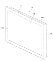
図1は、本発明の第1の実施形態である表示装置の外観斜視図、図2は図1に示す表示装置の分解斜視図である。
(First embodiment)
FIG. 1 is an external perspective view of a display device according to a first embodiment of the present invention, and FIG. 2 is an exploded perspective view of the display device shown in FIG.
図1及び図2に示すように、本実施形態の表示装置10は、ベゼル12、リアカバー19及び前面板13で構成される筐体10aと、筐体10a内に収容される表示パネル11とを有する。
As shown in FIGS. 1 and 2, the
ベゼル12には、画像表示範囲に対応する開口部12aが設けられている。また、ベゼル12及び前面板13は、押え金具15,16により狭持されている。押え金具15,16は、前面板13を押えるための金具である。
The
表示パネル11は、電子放出素子、プラズマ放電、液晶、蛍光表示管或いは有機EL(Electro Luminescence)などの薄型画像表示パネルが用いられる。表示パネル11の背面には、電気回路基板17が取り付けられている。
The
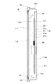
図3はリアカバー19の分解斜視図、図4は表示装置10の縦断面図である。
FIG. 3 is an exploded perspective view of the
図3及び図4に示すように、リアカバー19は、外壁部20及び内壁部21を有している。外壁部20は、放熱穴を設けておらず、外気から遮断されるようになっており、従って、筐体10a内へ塵埃が入らない構造となっている。
As shown in FIGS. 3 and 4, the
内壁部21は、板金21aと、板金21aに係合される板金21bとから構成され、板金21aと板金21bとの間には、断熱層として機能する密閉された空気層21c(図4参照)が形成される。
The
また、内壁部21の板金21aは、板金21bより上方に突出しており、該突出部分には、外壁部20側への強制的な空気の流れを形成するファン18を取り付けるための取付穴21dが複数箇所設けられている。
Further, the
そして、図4に示すように、内壁部21の板金21aの上端部を外壁部20に接合することにより、リアカバー19が組み立てられる。組み立てられた状態においては、内壁部21と下端部と外壁部20との間には、開口部19cが形成されるとともに、内壁部21の背面側と外壁部20との間には、空間19bが形成される。
Then, as shown in FIG. 4, the
このように構成されたリアカバー19は、押え金具15,16(押え金具16は図4では図示せず)を介してベゼル12に取り付けられている。
The
次に、図4を参照して、本実施形態の表示装置10の筐体10a内での空気の流れについて説明する。
Next, with reference to FIG. 4, the flow of air in the
リアカバー19の内壁部21に取り付けられているファン18の駆動により、筐体10a内の空気は、図4の矢印に示すように、表示パネル11と内壁部21との間の空間19aからリアカバー19の外壁部20と内壁部21との間の空間19bに流れ込む。
By driving the
前述したように、リアカバー19の外壁部20には放熱穴を設けていないので、筐体10a内の空気は、外部へ流出することなく、外壁部20と内壁部21との間の空間19bを下降する。
As described above, since the
そして、空間19bを下降する空気は、外壁部20と内壁部21の下端部との間の開口部19cから再び表示パネル11と電気回路基板17との間の空間19aへ流れ込む。
Then, the air descending the
即ち、表示パネル11と内壁部21との間の空間19aにある空気は、表示パネル11及び電気回路基板17等が発生する熱により暖められ上昇する。そして、空間19aで暖められて上昇した空気は、ファン18によりリアカバー19の外壁部20と内壁部21との間の空間19bに流入して下降し、その際に空気の熱が外壁部20を介して筐体10a外へ放熱される。
That is, the air in the
ここで、リアカバー19の内壁部21の板金21aと板金21bとの間には、前述したように、密閉された空気層21cが形成され、この空気層21cは、空気が循環している空間19a,19bとは隔離されて、断熱層として機能する。
Here, as described above, the sealed
このように、本実施形態では、リアカバー19の内壁部21の内部に密閉された空気層21cを設けているので、表示パネル11と電気回路基板17と間の空間19aで暖められた空気の熱や電気回路基板17が発生する熱が空気層21cで断熱されることになる。
Thus, in this embodiment, since the sealed
これにより、表示パネル11と電気回路基板17と間の空間19a側の熱が空間19b側を下降して放熱される空気に伝わりにくくなり、冷却効率(放熱効率)を上げることができる。
As a result, the heat on the
また、リアカバー19の内壁部21の内部に設けた空気層21cにより、短い距離で熱伝導率を低くすることができるので、電気回路基板17に対して放熱側の空間19bを接近配置することができ、表示装置10の薄型化及び軽量化を図ることができる。
In addition, the
更に、リアカバー19の外壁部20には放熱穴を設けておらず、外気から遮断されて筐体10a内へ塵埃が入らない構造となっているため、表示装置10の防塵性を確保することができる。
Further, the
(第2の実施形態)
次に、図5及び図6を参照して、本発明の第2の実施形態である表示装置について説明する。図5は本発明の第2の実施形態である表示装置の縦断面図、図6は図5に示す表示装置の横断面図である。なお、上記第1の実施形態に対して重複又は相当する部分については、図に同一符号を付してその説明を省略する。
(Second Embodiment)
Next, with reference to FIG.5 and FIG.6, the display apparatus which is the 2nd Embodiment of this invention is demonstrated. FIG. 5 is a longitudinal sectional view of a display device according to a second embodiment of the present invention, and FIG. 6 is a transverse sectional view of the display device shown in FIG. In addition, about the part which overlaps or corresponds to the said 1st Embodiment, the same code | symbol is attached | subjected to a figure and the description is abbreviate | omitted.
本実施形態では、図5及び図6に示すように、リアカバー19の外壁部20にヒートシンク22が設けられている。
In the present embodiment, as shown in FIGS. 5 and 6, a
ヒートシンク22には、外壁部20の外側で外気に露出するフィン22a及び外壁部20の内側で空間19bに露出するフィン22bが設けられている。
The
ファン18の駆動により電気回路基板17側の空間19aで暖められた空気がリアカバー19の外壁部20と内壁部21との間の空間19bに流れ込むと、該空気の熱がヒートシンク22のフィン22a及びフィン22bを通して外気へ放熱される。これにより、空気層21cの断熱効果と相まって更に冷却効率を上げることができる。
When the air heated in the
なお、ヒートシンク22の材質を、アルミ、銅等の熱伝導率の高い材質を用いることで、より高い冷却効果を得ることができる。その他の構成及び作用効果は、上記第1の実施形態と同様である。
Note that a higher cooling effect can be obtained by using a material having a high thermal conductivity such as aluminum or copper as the material of the
(第3の実施形態)
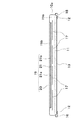
次に、図7及び図8を参照して、本発明の第3の実施形態である表示装置について説明する。図7は本発明の第3の実施形態である表示装置の縦断面図、図8は図7に示す表示装置の横断面図である。なお、上記第1の実施形態に対して重複又は相当する部分については、図に同一符号を付してその説明を省略する。
(Third embodiment)
Next, with reference to FIG.7 and FIG.8, the display apparatus which is the 3rd Embodiment of this invention is demonstrated. FIG. 7 is a longitudinal sectional view of a display device according to a third embodiment of the present invention, and FIG. 8 is a transverse sectional view of the display device shown in FIG. In addition, about the part which overlaps or corresponds to the said 1st Embodiment, the same code | symbol is attached | subjected to a figure and the description is abbreviate | omitted.
本実施形態では、図7及び図8に示すように、上記第1の実施形態に対して、リアカバー19の内壁部21の板金21aと板金21bとの配置を逆になっており、板金21bが冷却側の空間19bに面している。
In the present embodiment, as shown in FIGS. 7 and 8, the arrangement of the
板金21aは、電気回路基板17側で常に高温の熱に曝されており、板金21aに熱伝達された熱は、板金21aの面に沿って水平方向(図8の左右方向)に広がって、板金21aに連続する外壁部20との接合部へ伝達され、外壁部20を通して外気へ放熱される。
The
また、電気回路基板17上に高温の発熱源がある場合、その箇所に放熱シート29を設置し、放熱シート29を板金21aに接するようにする。
Further, when there is a high-temperature heat source on the
これにより、電気回路基板17からの熱は放熱シート29を通して板金21aへ伝達され、板金21aに伝達された熱は、面と水平方向(図8の左右方向)に広がって、外壁部20との接合部へ伝達され、外壁部20を通して外気へ放熱される。
Thereby, the heat from the
なお、内壁部21の内部の空気層21cにより板金21aの熱は板金21bに伝わりにくくなっているが、板金21aと板金21bとの接合部に熱伝導率が低いシート等を介装することで、板金21aから板金21bへ熱がさらに伝わりにくくすることも可能である。その他の構成及び作用効果は、上記第1の実施形態と同様である。
The heat of the
(第4の実施形態)
次に、図9を参照して、本発明の第4の実施形態である表示装置について説明する。図9は、本発明の第4の実施形態である表示装置の横断面図である。なお、上記第1の実施形態に対して重複又は相当する部分については、図に同一符号を付してその説明を省略する。
(Fourth embodiment)
Next, with reference to FIG. 9, the display apparatus which is the 4th Embodiment of this invention is demonstrated. FIG. 9 is a cross-sectional view of a display device according to the fourth embodiment of the present invention. In addition, about the part which overlaps or corresponds to the said 1st Embodiment, the same code | symbol is attached | subjected to a figure and the description is abbreviate | omitted.
電気回路基板17に実装される部品の高さによっては、上記第1の実施形態のように、リアカバー19全域で内壁部21を2重構造にすることができない場合があるので、本実施形態では、リアカバー19を、外壁部20と2つの内壁部21とにより構成している。
Depending on the height of the components mounted on the
即ち、冷却側の空間19bが横方向(図の左右方向)に互いに離間して2つ形成され、2つの内壁部21の各ファン18により電気回路基板17側の高温の空気が2つの空間19bに分かれて流れ込むようになっている。
That is, two cooling-
なお、本実施形態では、リアカバー19を、外壁部20と2つの内壁部21とにより構成しているが、リアカバー19を、外壁部20と3つ以上の内壁部21とにより構成するようにしてもよい。その他の構成及び作用効果は、上記第1の実施形態と同様である。
In the present embodiment, the
(第5の実施形態)
次に、図10を参照して、本発明の第5の実施形態である表示装置について説明する。
図10は、本発明の第5の実施形態である表示装置の縦断面図である。なお、上記第1の実施形態に対して重複又は相当する部分については、図に同一符号を付してその説明を省略する。
(Fifth embodiment)
Next, with reference to FIG. 10, the display apparatus which is the 5th Embodiment of this invention is demonstrated.
FIG. 10 is a longitudinal sectional view of a display device according to the fifth embodiment of the present invention. In addition, about the part which overlaps or corresponds to the said 1st Embodiment, the same code | symbol is attached | subjected to a figure and the description is abbreviate | omitted.
本実施形態では、リアカバー19の内壁部21の板金21aと板金21bとの間に、空気層を形成するのではなく、断熱材35を装填している。
In this embodiment, an air layer is not formed between the
断熱材35は、例えば発泡スチロールやその他の熱伝導率の低い部材を用いており、これにより、内壁部21の熱伝導率を低くして、電気回路基板17側の高温の熱が冷却側の空間19bに更に伝わりにくくなるようにしている。その他の構成及び作用効果は、上記第1の実施形態と同様である。
The
(第6の実施形態)
次に、図11及び図12を参照して、本発明の第6の実施形態である表示装置について説明する。図11は本発明の第6の実施形態である表示装置の縦断面図、図12は図11に示す表示装置の横断面図である。なお、上記第1の実施形態に対して重複又は相当する部分については、図に同一符号を付してその説明を省略する。
(Sixth embodiment)
Next, with reference to FIG.11 and FIG.12, the display apparatus which is the 6th Embodiment of this invention is demonstrated. FIG. 11 is a longitudinal sectional view of a display device according to a sixth embodiment of the present invention, and FIG. 12 is a transverse sectional view of the display device shown in FIG. In addition, about the part which overlaps or corresponds to the said 1st Embodiment, the same code | symbol is attached | subjected to a figure and the description is abbreviate | omitted.
本実施形態では、ファン18に代えて、図11及び図12に示すように、水冷パイプ39を用いている。
In the present embodiment, a water-cooled
水冷パイプ39は、リアカバー19の内壁部21の横方向(図12の左右方向)の一部において、縦方向(図11の上下方向)の全周域を取り囲むように設置されている。水冷パイプ39の内部には、筐体10a内の熱を放熱させる為に液体の冷媒が充填される。冷媒は、ポンプ40によって内壁部21の周囲を図11の矢印に示すように時計回り方向に循環する。
The water-cooled
水冷パイプ39は、電気回路基板17上に配置された複数のIC41に当接しており、IC17で発生した熱は水冷パイプ39へ伝達され、さらに水冷パイプ39内の冷媒へ伝達される。
The
そして、水冷パイプ39内の冷媒は、内壁部21の電気回路基板17側に沿って上昇して内壁部21の上方に達すると、外壁部20側に沿って下降し、該外壁部20を通して放熱される。
Then, when the refrigerant in the water-cooled
水冷パイプ39内を外壁部20側に沿って下降した冷媒は、ポンプ40により押し出され、再び電気回路基板17側へ循環される。
The refrigerant descending in the
このとき、内壁部21の内部には、空気層21cが設けられている為、水冷パイプ39内を外壁部20側に沿って下降する放熱側の冷媒に対して電気回路基板17側の熱が伝わりにくくなっており、効率良く放熱させることができる。
At this time, since the
なお、本実施形態では、ファン18を省略しているが、ファン18を設けて放熱効率を更に高めるようにしてもよく、また、図5及び図6に示すように、外壁部20にヒートシンクを設ける等して表面積を拡大することで、放熱効率を更に高めるようにしてもよい。その他の構成及び作用効果は、上記第1の実施形態と同様である。
In the present embodiment, the
なお、本発明は、上記各実施形態に例示したものに限定されるものではなく、本発明の要旨を逸脱しない範囲において適宜変更可能である。 In addition, this invention is not limited to what was illustrated by said each embodiment, In the range which does not deviate from the summary of this invention, it can change suitably.
10 表示装置
10a 筐体
11 表示パネル
12 ベゼル
13 前面板
15,16 押え金具
17 電気回路基板
18 ファン
19 リアカバー
20 外壁部
21 内壁部
21a 板金
21b 板金
21c 空気層
22 ヒートシンク
22a フィン
22b フィン
29 放熱シート
35 断熱材
39 水冷パイプ
40 ポンプ
41 IC
DESCRIPTION OF
Claims (7)
前記表示パネルの背面側に配置され、装置内の空気を外気から遮断するリアカバーと、
前記装置内の空気を循環させるためのファンと、
前記表示パネルと前記リアカバーとの間に配置される電気回路基板と、を備え、
前記リアカバーは、外壁部と、該外壁部と前記電気回路基板との間に配置される内壁部と、を有し、
前記内壁部は、2つの板金で構成されて、前記2つの板金の間に断熱層が形成され、かつ前記2つの板金のうちの前記表示パネル側の板金が前記外壁部に接合されるとともに、前記表示パネル側の板金と前記電気回路基板の発熱源との間に、放熱部材が設けられ、
前記ファンは、前記表示パネルと前記内壁部との間に形成される空間と、該内壁部と前記外壁部との間に形成される空間との間で空気を循環させることを特徴とする表示装置。 A display panel;
A rear cover that is disposed on the back side of the display panel and blocks air in the device from outside air;
A fan for circulating the air in the device;
An electric circuit board disposed between the display panel and the rear cover ,
The rear cover includes an outer wall portion, and an inner wall portion disposed between the outer wall portion and the electric circuit board ,
The inner wall portion is composed of two sheet metals, a heat insulating layer is formed between the two sheet metals , and the sheet metal on the display panel side of the two sheet metals is joined to the outer wall portion, A heat dissipation member is provided between the sheet metal on the display panel side and the heat source of the electric circuit board,
The fan circulates air between a space formed between the display panel and the inner wall portion and a space formed between the inner wall portion and the outer wall portion. apparatus.
前記ポンプは、前記内壁部の一部の周囲を取り囲むように配置されたパイプの内部に充填された冷媒を循環させ、
前記パイプには、前記電気回路基板の発熱源が当接することを特徴とする請求項1〜6のいずれか一項に記載の表示装置。 A pump for circulating the refrigerant in the device;
The pump circulates a refrigerant filled in a pipe disposed so as to surround a part of the inner wall portion,
The display device according to claim 1 , wherein a heat source of the electric circuit board contacts the pipe .
Priority Applications (1)
| Application Number | Priority Date | Filing Date | Title |
|---|---|---|---|
| JP2008097278A JP5188245B2 (en) | 2008-04-03 | 2008-04-03 | Display device |
Applications Claiming Priority (1)
| Application Number | Priority Date | Filing Date | Title |
|---|---|---|---|
| JP2008097278A JP5188245B2 (en) | 2008-04-03 | 2008-04-03 | Display device |
Publications (3)
| Publication Number | Publication Date |
|---|---|
| JP2009251175A JP2009251175A (en) | 2009-10-29 |
| JP2009251175A5 JP2009251175A5 (en) | 2011-05-19 |
| JP5188245B2 true JP5188245B2 (en) | 2013-04-24 |
Family
ID=41311979
Family Applications (1)
| Application Number | Title | Priority Date | Filing Date |
|---|---|---|---|
| JP2008097278A Expired - Fee Related JP5188245B2 (en) | 2008-04-03 | 2008-04-03 | Display device |
Country Status (1)
| Country | Link |
|---|---|
| JP (1) | JP5188245B2 (en) |
Cited By (1)
| Publication number | Priority date | Publication date | Assignee | Title |
|---|---|---|---|---|
| KR20140098360A (en) * | 2013-01-31 | 2014-08-08 | 엘지디스플레이 주식회사 | Display device |
Families Citing this family (5)
| Publication number | Priority date | Publication date | Assignee | Title |
|---|---|---|---|---|
| JP5388606B2 (en) * | 2009-01-29 | 2014-01-15 | 三洋電機株式会社 | Image display device |
| JP5434713B2 (en) * | 2010-03-17 | 2014-03-05 | パナソニック株式会社 | Heat dissipation unit and electronic device using the same |
| WO2011114660A1 (en) * | 2010-03-17 | 2011-09-22 | パナソニック株式会社 | Heat radiation unit for electronic apparatus, and electronic apparatus using same |
| KR102029054B1 (en) * | 2013-02-01 | 2019-10-07 | 엘지전자 주식회사 | Assembly for display apparatus |
| CN112162429A (en) * | 2020-09-01 | 2021-01-01 | 盐城华旭光电技术有限公司 | Light emitting diode and backlight module |
Family Cites Families (6)
| Publication number | Priority date | Publication date | Assignee | Title |
|---|---|---|---|---|
| JPH0826958B2 (en) * | 1991-04-18 | 1996-03-21 | 東洋酸素株式会社 | Vacuum insulation support method, vacuum insulation container and vacuum insulation panel using the same |
| JPH0519699A (en) * | 1991-07-16 | 1993-01-29 | Mitsubishi Electric Corp | Picture display device |
| JP2986297B2 (en) * | 1992-12-28 | 1999-12-06 | 日本信号株式会社 | LED display |
| JPH09307257A (en) * | 1996-05-20 | 1997-11-28 | Fujitsu General Ltd | Image display device |
| JP2003076286A (en) * | 2001-09-06 | 2003-03-14 | Ngk Insulators Ltd | Cooling system for display device |
| WO2008004280A1 (en) * | 2006-07-04 | 2008-01-10 | Fujitsu Limited | Heat radiation unit, heat radiator, and electronic apparatus |
-
2008
- 2008-04-03 JP JP2008097278A patent/JP5188245B2/en not_active Expired - Fee Related
Cited By (2)
| Publication number | Priority date | Publication date | Assignee | Title |
|---|---|---|---|---|
| KR20140098360A (en) * | 2013-01-31 | 2014-08-08 | 엘지디스플레이 주식회사 | Display device |
| KR102084609B1 (en) | 2013-01-31 | 2020-03-04 | 엘지디스플레이 주식회사 | Display device |
Also Published As
| Publication number | Publication date |
|---|---|
| JP2009251175A (en) | 2009-10-29 |
Similar Documents
| Publication | Publication Date | Title |
|---|---|---|
| JP5202220B2 (en) | Image display device | |
| JP5241416B2 (en) | Image display device | |
| JP5241415B2 (en) | Image display device | |
| CN110418997B (en) | Display device | |
| JP5234110B2 (en) | Liquid crystal display | |
| JP2010085783A (en) | Image display device | |
| JP5188245B2 (en) | Display device | |
| KR20140126912A (en) | Digital signage | |
| WO2009147898A1 (en) | Image display device | |
| JP2014512024A (en) | Display device | |
| JP2005265922A (en) | Plasma display device | |
| JP2009294284A (en) | Image display apparatus | |
| JP2006317906A (en) | Plasma display device | |
| JPH11296094A (en) | Heat radiating method of plasma display | |
| JP4656418B2 (en) | Lighting device and image display device | |
| JP2007155808A (en) | Display device with heat radiation structure and plasma display device with heat radiation structure | |
| KR20070113068A (en) | Heat-dissipating backlighting module for use in a flat panel display | |
| JP2006293349A (en) | Display module | |
| JP5241414B2 (en) | Image display device | |
| JP2008041638A (en) | Heat dissipation device for backlight light source for flat panel display | |
| JP2006227513A (en) | Display device | |
| JP2011180476A (en) | Image display device | |
| JP2009152146A (en) | Surface light source device and display device | |
| JP2009163152A (en) | Display apparatus | |
| WO2011077692A1 (en) | Planar light-source device, display device, and method for manufacturing a planar light-source device |
Legal Events
| Date | Code | Title | Description |
|---|---|---|---|
| A521 | Written amendment |
Free format text: JAPANESE INTERMEDIATE CODE: A523 Effective date: 20110330 |
|
| A621 | Written request for application examination |
Free format text: JAPANESE INTERMEDIATE CODE: A621 Effective date: 20110330 |
|
| A131 | Notification of reasons for refusal |
Free format text: JAPANESE INTERMEDIATE CODE: A131 Effective date: 20120710 |
|
| A977 | Report on retrieval |
Free format text: JAPANESE INTERMEDIATE CODE: A971007 Effective date: 20120711 |
|
| A521 | Written amendment |
Free format text: JAPANESE INTERMEDIATE CODE: A523 Effective date: 20120906 |
|
| TRDD | Decision of grant or rejection written | ||
| A01 | Written decision to grant a patent or to grant a registration (utility model) |
Free format text: JAPANESE INTERMEDIATE CODE: A01 Effective date: 20121225 |
|
| A61 | First payment of annual fees (during grant procedure) |
Free format text: JAPANESE INTERMEDIATE CODE: A61 Effective date: 20130122 |
|
| FPAY | Renewal fee payment (event date is renewal date of database) |
Free format text: PAYMENT UNTIL: 20160201 Year of fee payment: 3 |
|
| R151 | Written notification of patent or utility model registration |
Ref document number: 5188245 Country of ref document: JP Free format text: JAPANESE INTERMEDIATE CODE: R151 |
|
| FPAY | Renewal fee payment (event date is renewal date of database) |
Free format text: PAYMENT UNTIL: 20160201 Year of fee payment: 3 |
|
| LAPS | Cancellation because of no payment of annual fees |