JP5187807B2 - RFID card position recognition apparatus and method - Google Patents
RFID card position recognition apparatus and method Download PDFInfo
- Publication number
- JP5187807B2 JP5187807B2 JP2006317193A JP2006317193A JP5187807B2 JP 5187807 B2 JP5187807 B2 JP 5187807B2 JP 2006317193 A JP2006317193 A JP 2006317193A JP 2006317193 A JP2006317193 A JP 2006317193A JP 5187807 B2 JP5187807 B2 JP 5187807B2
- Authority
- JP
- Japan
- Prior art keywords
- rfid
- game card
- card
- rfid chip
- game
- Prior art date
- Legal status (The legal status is an assumption and is not a legal conclusion. Google has not performed a legal analysis and makes no representation as to the accuracy of the status listed.)
- Expired - Fee Related
Links
Images


Description
本発明は、RFID(Radio Frequency Identification)チップを具備するビデオゲーム用のカード(本明細書及び特許請求の範囲の記載において単に「ゲームカード」又は「RFIDカード」と言うものとする。)の位置、方位角、及び/又は表裏の別を認識するための装置及び方法に関するものである。 The present invention refers to the position of a video game card ( hereinafter simply referred to as “game card” or “RFID card” in the present specification and claims ) having an RFID (Radio Frequency Identification) chip . , An azimuth angle, and / or an apparatus for recognizing front / back distinction.
ゲーム機において、プレイヤーが所持するカードに記録されたデータをゲームに反映させるようにしたものは、従来から知られている。
即ち、例えば下記の特許文献1には、ICカードをゲーム機にセットすると、当該ゲームカードの記録データに基づき、そのICカードの表面に記載されているキャラクターと同じキャラクターがゲーム機のディスプレイ装置上に登場するように構成されたゲーム機が開示されている。
また、プレイヤーが個別に所持するカードに、そのプレイヤーのゲーム成績その他のゲーム履歴を記録し、その記録データを、後日ゲームを行う際に利用するように構成したゲーム機も、例えば下記の特許文献2において開示されている。
2. Description of the Related Art Conventionally, a game machine in which data recorded on a card possessed by a player is reflected in a game is known.
That is, for example, in
In addition, a game machine configured to record a player's game results and other game histories on a card individually possessed by the player and use the recorded data when playing a game at a later date is also disclosed in, for example, the following
しかしながら、従来のゲーム機は、ICカード等のゲームカードに記録されたゲーム履歴等のデータを利用して、ゲームの難易度を自動的に設定したり、前回の得点を引き継いでゲームを継続したりすることができるだけで、カードテーブル上にプレイヤーがゲームカードを置き、そのゲームカードの位置や向きをゲームに反映させ、それらをゲーム操作のための一つの手段として利用することは行われていなかった。
それは、ゲームカードの位置や向き、表裏の別を迅速かつ的確に検知できる装置及び方法が提供されていなかったことが一つの原因である。
However, conventional game machines use game history data recorded on a game card such as an IC card to automatically set the difficulty level of the game or continue the game by taking over the previous score. It is not possible for a player to place a game card on the card table, reflect the position and orientation of the game card in the game, and use them as a means for game operation. It was.
One reason for this is that an apparatus and method that can quickly and accurately detect the position and orientation of the game card and whether the game card is front or back have not been provided.
本発明は、上記の問題点を解決するためなされたものであり、その目的とするところは、カードテーブル上に置かれたRFIDカードの位置、方位角、及び/又は表裏の別を迅速かつ的確に認識し得る装置及び方法を提供することにより、RFIDカードを用いて様々なゲームのコンテンツの開発が可能なようにすることにある。 The present invention has been made to solve the above-described problems, and the object of the present invention is to quickly and accurately distinguish the position, azimuth and / or front / back of an RFID card placed on a card table. By providing an apparatus and method that can be recognized, it is possible to develop various game contents using an RFID card.
上記本発明の目的は、
カードテーブル(1)上に置かれた、それぞれ少なくとも1個のRFIDチップを具備する少なくとも1 枚のゲームカード(Cp、p =1 、2 ・・・s;但し、sはカード枚数)の位置を認識する装置であって、下記[a]項ないし[e]項記載の構成要素a乃至e、即ち、
[a]カードテーブル(1)の下面に格子状に配置された複数のRFIDリーダー(Rij 、i=1 、2 、・・・n 、j =1 、2 、・・・m)。
[b]各RFIDリーダー(Rij)毎に設けられる電波強度等検知回路(Sij )であって、各RFIDリーダー(Rij)の近傍に置かれたゲームカード(Cp、p =1 、2 ・・・s)のRFIDチップ(Gpq 、p =1 、2 、・・・s 、q =1 、2 、・・・t;tは各ゲームカードに設けられたRFIDチップの数)から発信され、各RFIDリーダー(Rij)によってそれぞれ受信された信号波Wijpq を解析し、各RFIDチップ(Gpq)毎にその受信された信号波Wijpq の強度Fijpq と当該RFIDチップ(Gpq)のIDコード(IDpq)とを検出する電波強度等検知回路(Sij)。
[c]電波強度等検知回路(Sij)により、各RFIDチップ(Gpq)毎に、その信号波強度Fijpqが検出されたRFIDリーダー(Rij)のうち、信号波強度の高いものから順に各3個の互いに隣接するRFIDリーダー(Rxu、Ryv、Rzw)を選択する比較選別回路(21a)。
[d]ゲームカード(Cp)に設けられた各RFIDチップ(Gpq )毎に選ばれたそれぞれ3個のRFIDリーダー(Rxu 、Ryv 、Rzw )により検出されたそれぞれの信号波強度Fxupq、Fyzpq、Fzwpqに基づき、当該RFIDチップの位置(Opq )を求めるRFIDチップ位置算出回路(21b)。
[e]RFIDチップ位置算出回路(21b)により得られた、ゲームカード(Cp)に設けられた各RFIDチップ(Gpq)の位置情報に基いて、ゲームカード(Cp)の位置を判定するゲームカード位置判定回路(21c)。
を備えたことを特徴とするゲームカードの位置認識装置により達成される。
上記本発明の他の目的は、
カードテーブル(1)上に置かれた、互いに離れた位置に配置された2 個のRFIDチップ(G11、G12)を具備するゲームカード(Cp)の方位角認識装置において、前記のゲームカードの位置認識装置に加えて、その位置認識装置により得られたそれら2 個のRFIDチップ(G11、G12)の位置データに基づいて、ゲームカード(Cp)の方位角を求める装置を設けて成るゲームカードの方位角認識装置により達成される。
上記本発明の更に他の目的は、
カードテーブル(1)上の互いに離れた位置であって一直線上にない位置に配置された3個のRFIDチップ(G11、G12、G13)を具備するゲームカード(Cp)の表裏の別認識装置において、前記のゲームカードの位置認識装置に加えて、そのゲームカードの位置認識装置により得られたそれら3個のRFIDチップ(G11、G12)の位置データに基づいて、ゲームカード(Cp)のカードの表裏の別を求める装置を設けて成るゲームカードの表裏の別認識装置により達成される。
The object of the present invention is as follows.
Placed on the card table (1), at least one game card comprises at least one RFID chip respectively (Cp, p = 1, 2 ··· s; however, s card number) the location of An apparatus for recognizing the components a to e described in the following items [a] to [e]:
[A] A plurality of RFID readers (Rij, i = 1, 2,... N, j = 1, 2,... M) arranged in a lattice pattern on the lower surface of the card table (1).
[B] A radio wave intensity detection circuit (Sij) provided for each RFID reader (Rij), which is a game card (Cp, p = 1, 2,... Placed in the vicinity of each RFID reader (Rij). s) RFID chips (Gpq, p = 1, 2,... s, q = 1, 2,... t; t is the number of RFID chips provided on each game card) The signal wave Wijpq received by the reader (Rij) is analyzed, and the intensity Fijpq of the received signal wave Wijpq and the ID code (IDpq) of the RFID chip (Gpq) are detected for each RFID chip (Gpq). A detection circuit (Sij) for detecting radio wave intensity.
[C] For each RFID chip (Gpq) detected by the radio wave intensity detection circuit (Sij), three RFID readers (Rij) from which the signal wave intensity Fijpq is detected, in order from the one with the highest signal wave intensity. Comparison and selection circuit (21a) for selecting RFID readers (Rxu, Ryv, Rzw) adjacent to each other.
[D] Signal wave strengths Fxupq, Fyzpq, Fzwpq detected by three RFID readers (Rxu, Ryv, Rzw) selected for each RFID chip (Gpq) provided on the game card (Cp) RFID chip position calculation circuit (21b) for obtaining the position (Opq) of the RFID chip based on the above.
[E] Game card for determining the position of the game card (Cp) based on the position information of each RFID chip (Gpq) provided in the game card (Cp) obtained by the RFID chip position calculation circuit (21b) Position determination circuit (21c) .
This is achieved by a game card position recognition device .
Another object of the present invention is as follows.
In the azimuth angle recognition device for a game card (Cp) comprising two RFID chips (G11, G12) placed on the card table (1) and spaced apart from each other, the position of the game card In addition to the recognition device, a game card comprising a device for determining the azimuth of the game card (Cp) based on the position data of the two RFID chips (G11, G12) obtained by the position recognition device. This is achieved by an azimuth recognition device.
Still another object of the present invention is as follows.
In a separate recognition device for the front and back of a game card (Cp) comprising three RFID chips (G11, G12, G13) arranged at positions apart from each other on the card table (1) but not in a straight line In addition to the game card position recognition device described above , based on the position data of the three RFID chips (G11, G12) obtained by the game card position recognition device, the card of the game card (Cp) This is achieved by a separate recognition device for the front and back of a game card, which is provided with a device for determining the front and back .
その場合において、上記RFIDチップ位置算出回路(21b)が、ゲームカード(Cp)に設けられた各RFIDチップ(Gpq )毎に選ばれたそれぞれ3 個のRFIDリーダー(Rxu 、Ryv 、Rzw )により検出されたそれぞれの信号波強度Fxupq、Fyzpq、Fzwpqに対応する等感度曲線(Cxupq 、Cyvpq 、Czwpq )を選択し、その交点(Opq) を求めることにより、当該RFIDチップの位置を求めるように構成することが可能である。 In that case, the RFID chip position calculation circuit (21b) is detected by three RFID readers (Rxu, Ryv, Rzw) selected for each RFID chip (Gpq) provided in the game card (Cp). By selecting the isosensitivity curves (Cxupq, Cyvpq, Czwpq) corresponding to the respective signal wave strengths Fxupq, Fyzpq, Fzwpq, and determining the intersection (Opq), the position of the RFID chip is determined. It is possible.
複数のRFIDリーダー(Rij )は、カードテーブル(1)の下面に三角格子状に配置することが推奨される。 It is recommended that a plurality of RFID readers (Rij) be arranged in a triangular lattice pattern on the lower surface of the card table (1).
各ゲームカードには、それぞれ各1 個のRFIDチップを取り付け、当該ゲームカードの位置のみを検出するようにしたり、或いはまた、それぞれ各2 個のRFIDチップを取り付け、当該ゲームカードの位置及び方位角を検出するようにしたり、更にはまた、それぞれ各3 個のRFIDチップを取り付け、当該ゲームカードの位置、方位角及び表裏の別を検出するようにしたり、等々、さまざまな実施態様が可能である。 Each game card is attached with one RFID chip, and only the position of the game card is detected, or each RFID card is attached with two RFID chips, and the position and azimuth of the game card are Various embodiments are possible, such as detecting the position, azimuth and front / back of the game card by attaching three RFID chips to each of them. .
上記本発明の更に別異の目的は、
下面に複数のRFIDリーダー(Rij 、i=1 、2 、・・・n 、j =1 、2 、・・・m)が格子状に配置されたカードテーブル(1)上に置かれた、それぞれ少なくとも1個のRFIDチップを具備する少なくとも1 枚のゲームカード(Cp、p =1 、2 ・・・s)の位置を認識する方法であって、下記[f]項ないし[i]項記載のステップ、即ち、
[f]各RFIDリーダー(Rij)の近傍に置かれたゲームカード(Cp、p =1 、s )のRFIDチップ(Gpq 、p =1 、2 、・・・s 、q =1 、2 、・・・t)から発信され、各RFIDリーダー(Rij)によってそれぞれ受信された信号波Wijpq を解析し、各RFIDチップ(Gpq)毎にその受信された信号波Wijpq の強度Fijpq と当該RFIDチップ(Gpq)のIDコード(IDpq)とを検出するステップ。
[g]各RFIDチップ(Gpq)毎に、その信号波強度Fijpqが検出されたRFIDリーダー(Rij)のうち、信号波強度の高いものから順に各3 個の互いに隣接するRFIDリーダー(Rxu 、Ryv 、Rzw )を選択するステップ。
[h]ゲームカード(Cp)に設けられた各RFIDチップ(Gpq)毎に選ばれたそれぞれ3 個のRFIDリーダー(Rxu 、Ryv 、Rzw)により検出されたそれぞれの信号波強度Fxupq、Fyzpq、Fzwpqに基づき、当該RFIDチップの位置(Opq )を求めるステップ。
[i]上記[h]項記載のステップにより得られた、ゲームカード(Cp)に設けられた各RFIDチップ(Gpq)の位置情報に基いて、ゲームカード(Cp)の位置を判定するステップ。
を順次実行することを特徴とするゲームカードの位置認識方法によって達成される。
上記本発明の更に別異の目的は、
2 個のRFIDチップ(G11、G12)を具備するゲームカード(Cp)の方位角認識方法において、上記のゲームカードの位置認識方法の各ステップf乃至iに加えて、それらのステップf乃至iにより得られたそれら2 個のRFIDチップ(G11、G12)の位置データに基づきゲームカード(Cp)方位角を求めるステップを設けて成る上記のゲームカードの方位角認識方法によって達成される。
上記本発明の更に別異の目的は、
3個のRFIDチップ(G11、G12、G13)を具備するゲームカード(Cp)の位置認識方法において、上記のゲームカードの位置認識方法の各ステップf乃至iに加えて、それらのステップf乃至iにより得られたそれら3個のRFIDチップ(G11、G12)の位置データに基づいてゲームカード(Cp)の表裏の別を求るステップを設けて成る、上記のゲームカードの表裏の別認識方法によって達成される。
Another object of the present invention is as follows.
A plurality of RFID readers (Rij, i = 1, 2,... N, j = 1, 2,... M) are placed on a card table (1) arranged in a grid on the lower surface, respectively. A method for recognizing the position of at least one game card (Cp, p = 1, 2,... S) having at least one RFID chip, according to items [f] to [i] below: Step, ie
[F] RFID chip (Gpq, p = 1, 2,..., S, q = 1, 2,... Of game card (Cp, p = 1, s) placed in the vicinity of each RFID reader (Rij)・ ・ Analysis of the signal wave Wijpq transmitted from t) and received by each RFID reader (Rij), and the intensity Fijpq of the received signal wave Wijpq and the RFID chip (Gpq) for each RFID chip (Gpq) ) ID code (IDpq).
[G] For each RFID chip (Gpq), among the RFID readers (Rij) from which the signal wave intensity Fijpq is detected, the three RFID readers (Rxu, Ryv) that are adjacent to each other in descending order of the signal wave intensity. , Rzw).
[H] Signal wave strengths Fxupq, Fyzpq, Fzwpq detected by three RFID readers (Rxu, Ryv, Rzw) selected for each RFID chip (Gpq) provided on the game card (Cp) The step of determining the position (Opq) of the RFID chip based on
[I] A step of determining a position of the game card (Cp) based on position information of each RFID chip (Gpq) provided in the game card (Cp) obtained by the step described in the above item [h].
Are sequentially executed to achieve the game card position recognition method .
Another object of the present invention is as follows.
In the azimuth angle recognition method for a game card (Cp) having two RFID chips (G11, G12), in addition to the steps f to i of the game card position recognition method, the steps f to i This is achieved by the above-described game card azimuth recognition method, which includes the step of obtaining the azimuth of the game card (Cp) based on the obtained position data of the two RFID chips (G11, G12).
Another object of the present invention is as follows.
In the game card (Cp) position recognition method comprising three RFID chips (G11, G12, G13), in addition to the steps f to i of the game card position recognition method, those steps f to i According to the above-described separate recognition method for the front and back of the game card, comprising the step of determining the front and back of the game card (Cp) based on the position data of the three RFID chips (G11, G12) obtained by Achieved.
その場合、上記[h]項記載のステップにおいて、ゲームカードの各RFIDチップ毎に、信号波強度の高いものから順に選ばれたそれぞれ3 個のRFIDリーダーにより検出されたそれぞれの信号波強度に対応する等感度曲線を選択し、その交点を求めることにより、当該RFIDチップの位置を求めるようにすることが推奨される。 In that case, in the step described in the above item [h], each RFID chip of the game card corresponds to each signal wave intensity detected by three RFID readers selected in descending order of signal wave intensity. It is recommended that the position of the RFID chip be determined by selecting the isosensitivity curve to be determined and determining the intersection.
上記の如き構成であると、カードテーブル上に置かれたRFIDカードの位置、方位角、及び/又は表裏の別を迅速かつ的確に判別可能なため、RFIDカードを用いて各種のゲーム操作が可能となり、従来にない様々なゲームのコンテンツ等の開発が可能となり、ゲームの興趣が大幅に向上するものである。 With the configuration as described above, the position, azimuth and / or front / back distinction of the RFID card placed on the card table can be quickly and accurately distinguished, so various game operations can be performed using the RFID card. Thus, it becomes possible to develop various game contents and the like that have not been heretofore, and the fun of the game is greatly improved.
以下、図面を参照しつつ、本発明を実施するための最良の形態について説明する。
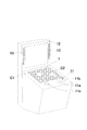
図1は、本発明に係るRFIDカードの位置等認識装置を備えたビデオゲーム機の一実施例の外観斜視図、
図2は、本発明に係るRFIDカードの位置等認識装置の回路構成の一実施例を示すブロック図、
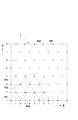
図3は、本発明に係るRFIDカードの位置等認識装置のカードテーブルの下面に配置される複数のRFIDリーダーの配置の一例を示す説明図、
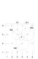
図4は、本発明に係るRFIDカードの位置等認識装置によりRFIDカードの位置を認識する原理を示す説明図、
図5は、本発明に係るRFIDカードの位置等認識装置によりRFIDカードの方位角を認識する原理を示す説明図、
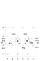
図6は、本発明に係るRFIDカードの位置等認識装置によりRFIDカードの表裏の別を認識する原理を示す説明図である。
The best mode for carrying out the present invention will be described below with reference to the drawings.
FIG. 1 is an external perspective view of an embodiment of a video game machine equipped with an RFID card position recognition device according to the present invention,
FIG. 2 is a block diagram showing an embodiment of the circuit configuration of the RFID card position recognition device according to the present invention,
FIG. 3 is an explanatory view showing an example of the arrangement of a plurality of RFID readers arranged on the lower surface of the card table of the RFID card position recognition device according to the present invention,
FIG. 4 is an explanatory diagram showing the principle of recognizing the position of the RFID card by the apparatus for recognizing the position and the like of the RFID card according to the present invention.
FIG. 5 is an explanatory view showing the principle of recognizing the azimuth angle of the RFID card by the RFID card position recognition device according to the present invention,
FIG. 6 is an explanatory diagram showing the principle of recognizing the front and back of the RFID card by the RFID card position recognition device according to the present invention.
図中、1はカードテーブル、11はゲーム操作部、11a,11bは操作ボタン、11cはジョイスティック、12はディスプレイ装置、13はスピーカー、2は中央制御装置、21は演算装置(CPU)、21aは比較選別回路、21bはRFIDチップ位置算出回路、21cはカード位置等判定回路、22はクロック回路、23はハードディスク、24はROM、25はRAM、26は画像処理装置、27はサウンド回路、28はデータバス、29はI/Oポート、Cp(p =1 、2 ・・・s )はゲームカード、Gpq(p =1 、2 、・・・s 、q =1 、2 、・・・t)はRFIDチップ、Rij(i=1 、2 、・・・n 、j =1 、2 、・・・m )はRFIDリーダー、Sij(i=1 、2 、・・・n 、j =1 、2 、・・・m )は電波強度等検知回路である。 In the figure, 1 is a card table, 11 is a game operation unit, 11a and 11b are operation buttons, 11c is a joystick, 12 is a display device, 13 is a speaker, 2 is a central control device, 21 is an arithmetic unit (CPU), 21a is Comparative selection circuit, 21b is an RFID chip position calculation circuit, 21c is a card position determination circuit, 22 is a clock circuit, 23 is a hard disk, 24 is ROM, 25 is RAM, 26 is an image processing device, 27 is a sound circuit, and 28 is Data bus, 29 is an I / O port, Cp (p = 1, 2,... S) is a game card, Gpq (p = 1, 2,... S, q = 1, 2,... T) Is an RFID chip, Rij (i = 1, 2,... N, j = 1, 2,... M) is an RFID reader, Sij (i = 1, 2,... N, j = 1, 2 ,... M) are detection circuits for radio wave intensity and the like.
図1に示すように、本発明に係るRFIDカードの位置等認識装置を備えたビデオゲーム機の筐体には、ゲームカードC1,C2を載せてゲームを行うカードテーブル1や、ゲーム操作部11、液晶パネル等から成るディスプレイ装置12、スピーカー13、等々が設けられる。
カードテーブル1上に置かれるゲームカードC1,C2等には、それぞれ少なくとも1個のRFIDチップが取り付けられており、これを利用して、ゲームカードC1,C2等の位置、方位角、及び/又は表裏の別が、後述する本発明に係るRFIDカードの位置等認識装置により判別され、それらのデータがゲーム展開のための情報として利用されるようになっている。
ゲーム操作部11は、プレイヤーがゲームを行なうために操作する操作ボタン11a,11bやジョイスティック11c等々の入力装置から構成されている。1台のビデオゲーム機で複数のプレイヤーが対戦プレイ可能なように構成する場合には、ゲーム操作部11が各プレイヤーに対応するように複数組設けられる。
ディスプレイ装置12は、ゲームの進行を示す画像や、ゲーム操作方法、ゲーム結果等々の各種情報を表示するためのものである。
スピーカー19は、各種効果音やプレイヤーへの音声指示を行なうものである。
As shown in FIG. 1, a card table 1 for playing a game by placing game cards C1 and C2 on a housing of a video game machine equipped with a device for recognizing the position and the like of an RFID card according to the present invention, and a
At least one RFID chip is attached to each of the game cards C1, C2 and the like placed on the card table 1, and using this, the position, azimuth, and / or the game cards C1, C2 and the like are used. The front / back is discriminated by an RFID card position recognition device according to the present invention, which will be described later, and these data are used as information for game development.
The
The
The speaker 19 performs various sound effects and voice instructions to the player.
中央制御装置2は、ゲーム機の筐体のプレイヤーから見えない内部に備えられ、CPU等から成る演算装置21、クロック回路22、ハードディスク23、ROM24、RAM25、画像処理装置26、サウンド回路27、データバス28、I/Oポート29、等々から構成されている。
この中央制御装置2は、ゲーム機全体の作動を統括制御する機能を有し、本発明のRFIDカードの位置等認識方法を実施するために必要な演算処理も、この中央制御装置2によって行われるようになっている。
中央制御装置2中の演算装置21はCPU等から成り、ハードディスク23にインストールされたゲームソフト(プログラム)に従い、プレイヤーの入力操作に応じたゲーム展開を行うための演算処理を実行するものである。本発明におけるRFIDカードの位置等の認識のための演算処理も、この演算装置21によって実行される。後述する比較選別回路21a、RFIDチップ位置算出回路21b、カード位置等判定回路21cも、ハードディスク23から読み出されたプログラムが、演算装置21のハードウェア資源と協働することによって構築されるものであるので、図2では、これらの回路を演算装置21内に破線のブロックとして表示した。
クロック回路22は、ゲーム機中の各種デジタル演算処理のためのベースとなるクロックパルスを発振する回路であり、ゲーム開始からゲームオーバーまでの時間管理や、ゲーム進行上必要なその他の時間管理等を行うためにも重要な役割を果たすものである。
The
The
The
The
ハードディスク23には、ゲームの進行を直接制御するゲームソフト(プログラム)のほか、ゲーム機全体の作動を統括制御する各種プログラム、及び、本発明によるRFIDカードの位置等の判別のためのプログラムがインストールされている。また、ゲームで使用される各種キャラクター画像や背景画像等の画像データや、効果音等の音声データも記録されている。
The
ROM24には、ゲーム機の管理データ、ゲーム機内の各機器の初期設定データ、等々が記録されている。
RAM25は、演算装置21の動作に必要なデータの授受を演算装置21との間で行なう。
画像処理装置26は、ハードディスク23に記録された画像データをもとに演算装置21により指定されたゲーム画面の映像を編成する。
サウンド回路27は、効果音やプレイヤーへの音声指示信号をアナログ変換し増幅して、スピーカー13に供給する。
データバス28は、上記各種回路間のデータ伝送線路である。
I/Oポート29は、ゲーム操作部11や後述する電波強度等検知回路Sij等の外部回路と中央制御装置2とを接続するインターフェイスである。
The
The
The
The
The
The I /
以下、本発明の構成について、具体的に説明する。
本発明で用いられる少なくとも1 枚のゲームカードCp(p =1 、2 ・・・s )には、それぞれ少なくとも1個のRFIDチップGpq(p =1 、2 、・・・s 、q =1 、2 、・・・t)が取り付けられている。
具体的には、例えば図4に示すゲームカードC1には、その中央に1個のRFIDチップG11が取り付けられ、また図5に示すゲームカードC1には、その一方の長辺に沿って2個のRFIDチップG11及びG12が取り付けられている。更にまた、図6に示すゲームカードC1には、その一方の長辺に沿って2個のRFIDチップG11及びG12が取り付けられ、また、一方の短辺に沿って2個のRFIDチップG11及びG13が取り付けられている(RFIDチップG11は長辺と短辺について共通)。
Hereinafter, the configuration of the present invention will be specifically described.
At least one game card Cp (p = 1, 2,... S) used in the present invention has at least one RFID chip Gpq (p = 1, 2,... S, q = 1, 2,... T) are attached.
Specifically, for example, in the game card C1 shown in FIG. 4, one RFID chip G11 is attached in the center, and in the game card C1 shown in FIG. RFID chips G11 and G12 are attached. Furthermore, two RFID chips G11 and G12 are attached along one long side of the game card C1 shown in FIG. 6, and two RFID chips G11 and G13 are attached along one short side. (RFID chip G11 is common to long side and short side).
ゲーム機の筐体に設けたカードテーブル1の下面には、上記ゲームカードのRFIDチップと交信を行うための複数のRFIDリーダーRij (i=1 、2 、・・・n 、j =1 、2 、・・・m )が格子状に配置されている。
具体的には、例えば図3に示すカードテーブル1の下面には、格子状に配列された正三角形の各頂点に位置するようにRFIDリーダーRij が配置されている。
以下、これら多数のRFIDリーダーを個別に表記する場合には、図3に示す如く、X軸方向の配列位置に順番に1 、2 、・・・n の番号を振り、同様にY軸方向の配列位置にも順番に1 、2 、・・・m の番号を振った上で、「X軸位置2、Y軸位置4」に取り付けられているRFIDリーダーは「R24」と表示し、同様に、「X軸位置9、Y軸位置7」に取り付けられているRFIDリーダーは「R97」と表示するものとする。
A plurality of RFID readers Rij (i = 1, 2,..., N, j = 1, 2 for communicating with the RFID chip of the game card are provided on the lower surface of the card table 1 provided in the casing of the game machine. ,... M) are arranged in a grid pattern.
Specifically, for example, an RFID reader Rij is disposed on the lower surface of the card table 1 shown in FIG. 3 so as to be positioned at each vertex of an equilateral triangle arranged in a lattice pattern.
In the following description, when a large number of RFID readers are individually indicated,
上記多数のRFIDリーダーRij に対しては、それぞれのRFIDリーダーごとに、
電波強度等検知回路Sij (i=1 、2 、・・・n 、j =1 、2 、・・・m )が設けられている。図2においては、図面の煩雑化を防ぐため、当該電波強度等検知回路Sij を1個のブロックで描いてあるが、実際には、各RFIDリーダーごとにそれぞれ個別に電波強度等検知回路が設けられるものである。
これらの電波強度等検知回路Sij の機能は、各RFIDリーダーRij の近傍に置かれたゲームカードCpのRFIDチップGpq から発信され、各RFIDリーダーRij によってそれぞれ受信された信号波Wijpq を解析し、各RFIDチップGpq (p =1 、2 、・・・s 、q =1 、2 、・・・t)毎にその受信された信号波Wijpq の強度Fijpq と当該RFIDチップGpq のIDコードIDpqとを検出することにある。
即ち、RFIDカードCpがカードテーブル1上の任意の位置に置かれると、当該RFIDカードに取り付けられたRFIDチップGpqは、近傍のRFIDリーダーからの指令信号に応答する形で、みずからのIDコードIDpqその他のデータを含む信号波Wijpq を発信する。
そこで、当該RFIDチップGpqの周囲に存在する複数のRFIDリーダーRij で受信された上記信号波Wijpq は、それぞれのRFIDリーダーRij ごとに設けた前記電波強度等検知回路Sij により解析され、各信号波Wijpq の強度Fijpq と当該RFIDチップGpq のIDコードIDpqとが検出される。当該強度Fijpq は、同一のRFIDチップGpqからの信号波Wijpq についてのものであっても、当該RFIDチップGpqと複数のRFIDリーダーRij との距離が相違するため互いに相違するが、IDコードIDpqは、同一のRFIDチップGpq から発信されたものであれば、どのRFIDリーダーRij で受信されるものも当然同一である。
For each of the above RFID readers Rij, for each RFID reader,
A detection circuit Sij (i = 1, 2,..., N, j = 1, 2,... M) is provided. In FIG. 2, the radio wave intensity detection circuit Sij is drawn as one block to prevent the drawing from becoming complicated, but actually, each RFID reader has a radio wave intensity detection circuit individually provided. It is what
The function of the detection circuit Sij such as the radio wave intensity is analyzed from the signal wave Wijpq transmitted from the RFID chip Gpq of the game card Cp placed in the vicinity of each RFID reader Rij and received by each RFID reader Rij. For each RFID chip Gpq (p = 1, 2,... S, q = 1, 2,... T), the intensity Fijpq of the received signal wave Wijpq and the ID code IDpq of the RFID chip Gpq are detected. There is to do.
That is, when the RFID card Cp is placed at an arbitrary position on the card table 1, the RFID chip Gpq attached to the RFID card responds to a command signal from a nearby RFID reader, and the ID code IDpq is generated. A signal wave Wijpq containing other data is transmitted.
Therefore, the signal wave Wijpq received by a plurality of RFID readers Rij existing around the RFID chip Gpq is analyzed by the radio wave intensity detection circuit Sij provided for each RFID reader Rij, and each signal wave Wijpq is analyzed. Strength Fijpq and the ID code IDpq of the RFID chip Gpq are detected. Even if the intensity Fijpq is for the signal wave Wijpq from the same RFID chip Gpq, the distance between the RFID chip Gpq and the plurality of RFID readers Rij is different from each other, but the ID code IDpq is Of course, what is received by any RFID reader Rij is the same as long as it originates from the same RFID chip Gpq.
これを、図4に示した例を参照しつつ説明すれば、1個のRFIDチップG11を取り付けたゲームカードC1をカードテーブル上に置いたとき、RFIDチップG11から発信された信号波をその近傍のRFIDリーダーR33、R42、R53で受信して得られるそれぞれの信号波W3311、W4211、W5311の電波強度及びIDコードID11を、それぞれの電波強度等検知回路S33、S42、S53によって解析するものである。
その場合、信号波強度は1個のRFIDチップG11から各RFIDリーダーR33、R42、R53までの距離がそれぞれ異なるため、各RFIDリーダーR33、R42、R53においてそれぞれ得られる信号波W3311、W4211、W5311の強度はそれぞれ異なっている。
これに対して、信号波W3311、W4211、W5311に含まれるIDコードは、1個のRFIDチップG11から発信されたものであるからいずれも同一(ID11)である。
図4では、1個のRFIDチップG11しか描いてないが、実際には、複数枚のゲームカードがカードテーブル上に同時に置かれたり、また、1枚のゲームカードに複数個のRFIDチップが取り付けられている場合もあるので、各RFIDリーダーR33、R42、R53は、それぞれ複数のRFIDチップからの信号波を受信するものであり、従って、各RFIDリーダーR33、R42、R53ごとに設けた電波強度等検知回路S33、S42、S53は、複数の信号波についての信号波強度及びIDコードを解析、検出するものである。
This will be described with reference to the example shown in FIG. 4. When a game card C1 with one RFID chip G11 is placed on the card table, the signal wave transmitted from the RFID chip G11 is in the vicinity thereof. The radio wave intensity of each signal wave W3311, W4211, W5311 and ID code ID11 obtained by receiving with the RFID readers R33, R42, R53 of the RFID reader R33, R42, R53 are analyzed by the respective radio wave intensity detection circuits S33, S42, S53. .
In this case, since the signal wave intensity is different from one RFID chip G11 to each RFID reader R33, R42, R53, the signal waves W3311, W4211, W5311 respectively obtained in each RFID reader R33, R42, R53 are different. The strength is different.
In contrast, the ID codes included in the signal waves W3311, W4211, and W5311 are the same (ID11) because they are transmitted from one RFID chip G11.
In FIG. 4, only one RFID chip G11 is drawn, but actually, a plurality of game cards are placed on the card table at the same time, or a plurality of RFID chips are attached to one game card. Therefore, each RFID reader R33, R42, R53 receives signal waves from a plurality of RFID chips, and accordingly, the radio field strength provided for each RFID reader R33, R42, R53. The equal detection circuits S33, S42, and S53 analyze and detect the signal wave intensity and ID code for a plurality of signal waves.
次いで、比較選別回路21aは、上記により検出されたIDコードをもとに、各RFIDチップGpq 毎に、その信号波強度Fijpqが検出されたRFIDリーダーRij のうち、信号波強度の高いものから順に各3個の互いに隣接するRFIDリーダーRxu 、Ryv 、Rzw を選択する作業を行う。
即ち、図4の例では、RFIDチップG11からの信号波はその周囲の多くのRFIDリーダーRij によって受信されるが、その信号波強度は、RFIDチップG11に近い順の3個で、互いに隣接したもの、即ち、RFIDリーダーR33、R53、R42が選択されることになる。即ち、RFIDチップG11からの同一のIDコードID11を含む信号波のうちから、信号波強度の高いものから順に3個のRFIDリーダーを選べば、上記RFIDリーダーR33、R53、R42が選択されることになるものである。
Next, the comparison /
That is, in the example of FIG. 4, the signal wave from the RFID chip G11 is received by many RFID readers Rij around it, but the signal wave intensity is adjacent to the RFID chip G11 in the order close to the RFID chip G11. That is, the RFID readers R33, R53, and R42 are selected. That is, the RFID readers R33, R53, and R42 are selected by selecting three RFID readers in descending order of the signal wave intensity from the signal waves including the same ID code ID11 from the RFID chip G11. It will be.
次いで、上記の如くしてゲームカードCpに設けられた各RFIDチップGpq 毎に選ばれたそれぞれ3 個のRFIDリーダーRxu 、Ryv 、Rzw により検出されたそれぞれの信号波強度Fxupq、Fyzpq、Fzwpqに基づき、RFIDチップ位置算出回路21bによって当該RFIDチップGpq の位置Opq が求められる。
図4に示した例で説明すれば、ゲームカードC1のRFIDチップG11から発信され、上記3個のRFIDリーダーR33、R42、R53においてそれぞれ受信された信号波W3311、W4211、W5311の信号波強度F3311、F4211、F5311に基づいて、RFIDチップ位置算出回路21bはRFIDチップG11の位置O11を算出する。
即ち、特定のRFIDチップG11から発信される電波の強度は、発信源からの距離に応じて減少するから、その減少関数と、発信出力と、受信された電波強度(いずれも既知)に基づいて演算を行うことにより、発信源であるRFIDチップG11から各RFIDリーダーR33、R42、R53までの距離をそれぞれ算出することが可能である。そこで、上記3個のRFIDリーダーR33、R42、R53からそれぞれ上記の距離に該当する点の位置を求めれば、これがRFIDチップG11の位置O11として求められることとなる。
即ち、図4に示す如く、各RFIDリーダーR33、R42、R53を中心にして上記距離に相当する半径の円をそれぞれ描けば、これらの3つの円の交点がRFIDチップG11の存在位置O11として求められるものである。
Next, based on the respective signal wave strengths Fxupq, Fyzpq, Fzwpq detected by the three RFID readers Rxu, Ryv, Rzw selected for each RFID chip Gpq provided on the game card Cp as described above. Then, the position Opq of the RFID chip Gpq is obtained by the RFID chip
In the example shown in FIG. 4, the signal wave intensity F3311 of the signal waves W3311, W4211, and W5311 transmitted from the RFID chip G11 of the game card C1 and received by the three RFID readers R33, R42, and R53, respectively. Based on F4211, F5311, the RFID chip
That is, the intensity of the radio wave transmitted from a specific RFID chip G11 decreases according to the distance from the transmission source, and therefore based on the decreasing function, the transmission output, and the received radio field intensity (all known). By performing the calculation, it is possible to calculate the distances from the RFID chip G11, which is a transmission source, to the RFID readers R33, R42, and R53, respectively. Thus, if the positions of the points corresponding to the above distances are obtained from the three RFID readers R33, R42, and R53, this is obtained as the position O11 of the RFID chip G11.
That is, as shown in FIG. 4, if each of the RFID readers R33, R42, and R53 is centered on a circle having a radius corresponding to the above distance, the intersection of these three circles is obtained as the existence position O11 of the RFID chip G11. It is what
換言すれば、各RFIDリーダーR33、R42、R53からRFIDチップG11までの距離をそれぞれ求めるための演算を行うことなく、各RFIDリーダーR33、R42、R53により検出されたそれぞれの信号波強度F3311、F4211、F5311に対応する等感度曲線(図4における各RFIDリーダーR33、R42、R53を中心とする破線の円)を選択し、その交点を求めることにより、当該RFIDチップG11の位置O11を求め得るものである。
この演算処理を、RFIDチップ位置算出回路21bによって行うものである。
なお、上記の如く、3 個のRFIDリーダーRxu 、Ryv 、Rzw により検出された信号波強度Fxupq、Fyzpq、Fzwpqに基づき、発信源である特定のRFIDチップGpq の位置Opq を求める演算方法としては、上記の方法に限らず、任意の演算方法を利用することができる。
In other words, the signal wave intensities F3311, F4211 detected by the RFID readers R33, R42, R53 without performing calculations for obtaining the distances from the RFID readers R33, R42, R53 to the RFID chip G11, respectively. By selecting the isosensitivity curve corresponding to F5311 (broken circles centered on the RFID readers R33, R42, and R53 in FIG. 4) and obtaining the intersection point, the position O11 of the RFID chip G11 can be obtained. It is.
This calculation process is performed by the RFID chip
As described above, based on the signal wave intensities Fxupq, Fyzpq, and Fzwpq detected by the three RFID readers Rxu, Ryv, and Rzw, a calculation method for obtaining the position Opq of the specific RFID chip Gpq that is a transmission source is as follows. Not limited to the above method, any calculation method can be used.
最後に、上記の如くしてRFIDチップ位置算出回路21bにより得られた、ゲームカードCpに設けられた各RFIDチップGpq の位置情報に基いて、カード位置等判定回路21cにより、ゲームカードCpの位置、方位角、及び/又は表裏の別を判定する。
例えば、図4に示すゲームカードC1のように、1 個のRFIDチップG11を有するゲームカードであれば、ゲームカード上におけるRFIDチップの取付け位置はあらかじめ知られているから、上記の如くしてRFIDチップG11の位置が求められれば、これから直ちにゲームカードC1の位置を求めることができる。
また、図5に示すゲームカードC1のように、2個のRFIDチップG11及びG12を有するゲームカードであれば、上記の如くしてこれらのRFIDチップの位置が求められれば、ゲームカードC1の位置が求められると共に、図示する如く、例えばこれら2個のRFIDチップを結ぶ線がX軸方向となす角度αを演算によって求めることができ、これにより、ゲームカードC1の方位角をも求めることができる。
Finally, based on the position information of each RFID chip Gpq provided in the game card Cp obtained by the RFID chip
For example, in the case of a game card having one RFID chip G11, such as the game card C1 shown in FIG. 4, the mounting position of the RFID chip on the game card is known in advance. If the position of the chip G11 is obtained, the position of the game card C1 can be obtained immediately.
Further, in the case of a game card having two RFID chips G11 and G12 as in the game card C1 shown in FIG. 5, if the positions of these RFID chips are obtained as described above, the position of the game card C1 In addition, as shown in the figure, for example, an angle α formed by a line connecting these two RFID chips with the X-axis direction can be obtained by calculation, whereby the azimuth angle of the game card C1 can also be obtained. .
更にまた、図6に示すゲームカードC1のように、3個のRFIDチップG11、G12及びG13を有するゲームカードであれば、このカードが表向きに置かれたときと、裏向きに置かれたときとでは、3個のRFIDチップの位置関係が相違するので、前記の如くしてこれらのRFIDチップの位置が求められれば、それらの位置関係も判別でき、これによってゲームカードC1が表向きにして置かれているか、裏向きにして置かれているかの区別を判定することができる。
従って、図6に示すゲームカードC1のように、3個のRFIDチップG11、G12及びG13を有するゲームカードであれば、その1個のRFIDチップの位置を求めることにより、図4の場合と同様にゲームカードC1の位置を求めることができ、また、3個のうち2個のRFIDチップの位置を求めることにより、図5の場合と同様にゲームカードC1の方位角も求めることができ、更に、3個のRFIDチップの位置を求めることにより、図6に示す如く、ゲームカードC1の表裏の別をも判別できるものである。
これらの演算、判別は、カード位置等判定回路21cによって行われる。
Furthermore, in the case of a game card having three RFID chips G11, G12, and G13, such as the game card C1 shown in FIG. 6, the card is placed face up and face down. Since the positional relationship between the three RFID chips is different, if the positions of these RFID chips are determined as described above, the positional relationship can also be determined, whereby the game card C1 is placed face up. It is possible to determine whether it is placed or placed face down.
Therefore, in the case of a game card having three RFID chips G11, G12, and G13, such as the game card C1 shown in FIG. 6, the position of the single RFID chip is obtained, as in the case of FIG. In addition, the position of the game card C1 can be obtained, and by obtaining the positions of two of the three RFID chips, the azimuth angle of the game card C1 can be obtained as in the case of FIG. By obtaining the positions of the three RFID chips, it is possible to discriminate between the front and back of the game card C1 as shown in FIG.
These calculations and determinations are performed by the card
なお、本発明に係るRFIDカードの位置等認識装置における上記の如き演算処理は、前記の如く、中央制御装置2のハードディスク23等のハードウェアに組み込まれた所定のコンピュータープログラムを演算装置21等を用いて実行することにより実現されるものである。
Note that the arithmetic processing as described above in the RFID card position recognition device according to the present invention, as described above, uses a predetermined computer program incorporated in hardware such as the
なお、本発明は上記の実施例に限定されるものではなく、その目的の範囲内において、上記の説明から当業者が容易に想到し得るすべての変更実施例を包摂するものである。 The present invention is not limited to the above-described embodiments, and includes all modified embodiments that can be easily conceived by those skilled in the art from the above description within the scope of the object.
本発明は上記の如く構成され、カードテーブル上に置かれたRFIDカードの位置、方位角、及び/又は表裏の別を迅速かつ的確に判別することができるため、RFIDカードを用いて各種のゲーム操作が可能となり、従来にない様々なゲームのコンテンツ等の開発が可能となり、従来にない興趣に富んだ新規なゲーム機を提供し得るものであるから、ゲーム機産業の発達に寄与するところ甚大である。 The present invention is configured as described above, and can quickly and accurately discriminate the position, azimuth, and / or front / back of an RFID card placed on a card table. It will be possible to operate and develop various game contents that are not available in the past, and it will be possible to provide a new game machine with an unprecedented interest, so it will contribute to the development of the game machine industry. It is.
1 カードテーブル
11 ゲーム操作部
11a,11b 操作ボタン
11c ジョイスティック
12 ディスプレイ装置
13 スピーカー
2 中央制御装置
21 演算装置(CPU)
21a 比較選別回路
21b RFIDチップ位置算出回路
21c カード位置等判定回路
22 クロック回路
23 ハードディスク
24 ROM
25 RAM
26 画像処理装置
27 サウンド回路
28 データバス
29 I/Oポート
Cp ゲームカード
Gpq RFIDチップ
Rij RFIDリーダー
Sij 電波強度等検知回路
DESCRIPTION OF
21a Comparison and
25 RAM
26
Cp game card
Gpq RFID chip
Rij RFID reader
Sij Signal strength detection circuit
Claims (12)
[a]カードテーブル(1)の下面に格子状に配置された複数のRFIDリーダー(Rij 、i=1 、2 、・・・n 、j =1 、2 、・・・m)。
[b]各RFIDリーダー(Rij)毎に設けられる電波強度等検知回路(Sij)であって、各RFIDリーダー(Rij)の近傍に置かれたゲームカード(Cp、p =1 、2 ・・・s)のRFIDチップ(Gpq 、p =1 、2 、・・・s 、q =1 、2 、・・・t;tは各ゲームカードに設けられたRFIDチップの数)から発信され、各RFIDリーダー(Rij)によってそれぞれ受信された信号波Wijpq を解析し、各RFIDチップ(Gpq)毎にその受信された信号波Wijpq の強度Fijpq と当該RFIDチップ(Gpq)のIDコード(IDpq)とを検出する電波強度等検知回路(Sij)。
[c]電波強度等検知回路(Sij)により、各RFIDチップ(Gpq)毎に、その信号波強度Fijpqが検出されたRFIDリーダー(Rij)のうち、信号波強度の高いものから順に各3個の互いに隣接するRFIDリーダー(Rxu、Ryv、Rzw)を選択する比較選別回路(21a)。
[d]ゲームカード(Cp)に設けられた各RFIDチップ(Gpq)毎に選ばれたそれぞれ3個のRFIDリーダー(Rxu 、Ryv 、Rzw)により検出されたそれぞれの信号波強度Fxupq、Fyzpq、Fzwpqに基づき、当該RFIDチップの位置(Opq)を求めるRFIDチップ位置算出回路(21b)。
[e]RFIDチップ位置算出回路(21b)により得られた、ゲームカード(Cp)に設けられた各RFIDチップ(Gpq)の位置情報に基いて、ゲームカード(Cp)の位置を判定するゲームカード位置判定回路(21c)。 Position recognition of at least one game card (Cp, p = 1, 2,... S, where s is the number of cards) each having at least one RFID chip placed on the card table (1) A device for recognizing a position of a game card, comprising the components described in the following items [a] to [e].
[A] A plurality of RFID readers (Rij, i = 1, 2,... N, j = 1, 2,... M) arranged in a lattice pattern on the lower surface of the card table (1).
[B] A radio wave intensity detection circuit (Sij) provided for each RFID reader (Rij), which is a game card (Cp, p = 1, 2,... Placed in the vicinity of each RFID reader (Rij). s) RFID chips (Gpq, p = 1, 2,... s, q = 1, 2,... t; t is the number of RFID chips provided on each game card) The signal wave Wijpq received by the reader (Rij) is analyzed, and the intensity Fijpq of the received signal wave Wijpq and the ID code (IDpq) of the RFID chip (Gpq) are detected for each RFID chip (Gpq). A detection circuit (Sij) for detecting radio wave intensity.
[C] For each RFID chip (Gpq) detected by the radio wave intensity detection circuit (Sij), three RFID readers (Rij) from which the signal wave intensity Fijpq is detected, in order from the one with the highest signal wave intensity. Comparison and selection circuit (21a) for selecting RFID readers (Rxu, Ryv, Rzw) adjacent to each other.
[D] Signal wave strengths Fxupq, Fyzpq, Fzwpq detected by three RFID readers (Rxu, Ryv, Rzw) selected for each RFID chip (Gpq) provided on the game card (Cp) RFID chip position calculation circuit (21b) for obtaining the position (Opq) of the RFID chip based on the above.
[E] Game card for determining the position of the game card (Cp) based on the position information of each RFID chip (Gpq) provided in the game card (Cp) obtained by the RFID chip position calculation circuit (21b) Position determination circuit (21c) .
[f]各RFIDリーダー(Rij)の近傍に置かれたゲームカード(Cp、p=1、2、・・・s)のRFIDチップ(Gpq 、p =1 、2 、・・・s 、q =1 、2 、・・・t)から発信され、各RFIDリーダー(Rij)によってそれぞれ受信された信号波Wijpq を解析し、各RFIDチップ(Gpq)毎にその受信された信号波Wijpq の強度Fijpq と当該RFIDチップ(Gpq)のIDコード(IDpq)とを検出するステップ。
[g]各RFIDチップ(Gpq)毎に、その信号波強度Fijpqが検出されたRFIDリーダー(Rij)のうち、信号波強度の高いものから順に各3 個の互いに隣接するRFIDリーダー(Ri,j、Ri,j+1、Ri+1,j )を選択するステップ。
[h]ゲームカード(Cp)に設けられた各RFIDチップ(Gpq)毎に選ばれたそれぞれ3 個のRFIDリーダー(Ri,j、Ri,j+1、Ri+1,j)により検出されたそれぞれの信号波強度Fxupq、Fyzpq、Fzwpqに基づき、当該RFIDチップの位置(Opq)を求めるステップ。
[i]上記[h]項記載のステップにより得られた、ゲームカード(Cp)に設けられた各RFIDチップ(Gpq)の位置情報に基いて、ゲームカード(Cp)の位置を判定するステップ。 A plurality of RFID readers (Rij, i = 1, 2,..., N, j = 1, 2,... M) are placed on a card table (1) arranged in a grid on the lower surface, respectively. A method for recognizing the position of at least one game card (Cp, p = 1, 2,... S) having at least one RFID chip, comprising the following items [f] to [i]: A game card position recognition method characterized by sequentially executing steps.
[F] RFID chip (Gpq, p = 1, 2,..., S, q = of a game card (Cp, p = 1, 2,... S) placed in the vicinity of each RFID reader (Rij) 1, 2,... T), and the signal wave Wijpq transmitted from each RFID reader (Rij) is analyzed, and the intensity Fijpq of the received signal wave Wijpq for each RFID chip (Gpq) Detecting an ID code (IDpq) of the RFID chip (Gpq);
[G] For each RFID chip (Gpq), among the RFID readers (Rij) from which the signal wave intensity Fijpq is detected, three adjacent RFID readers ( Ri, j , Ri, j + 1, Ri + 1, j ).
[H] Detected by three RFID readers ( Ri, j, Ri, j + 1, Ri + 1, j ) selected for each RFID chip (Gpq) provided on the game card (Cp) A step of obtaining the position (Opq) of the RFID chip based on the respective signal wave strengths Fxupq, Fyzpq, and Fzwpq.
[I] A step of determining a position of the game card (Cp) based on position information of each RFID chip (Gpq) provided in the game card (Cp) obtained by the step described in the above item [h].
Priority Applications (1)
| Application Number | Priority Date | Filing Date | Title |
|---|---|---|---|
| JP2006317193A JP5187807B2 (en) | 2006-11-24 | 2006-11-24 | RFID card position recognition apparatus and method |
Applications Claiming Priority (1)
| Application Number | Priority Date | Filing Date | Title |
|---|---|---|---|
| JP2006317193A JP5187807B2 (en) | 2006-11-24 | 2006-11-24 | RFID card position recognition apparatus and method |
Publications (2)
| Publication Number | Publication Date |
|---|---|
| JP2008125972A JP2008125972A (en) | 2008-06-05 |
| JP5187807B2 true JP5187807B2 (en) | 2013-04-24 |
Family
ID=39552379
Family Applications (1)
| Application Number | Title | Priority Date | Filing Date |
|---|---|---|---|
| JP2006317193A Expired - Fee Related JP5187807B2 (en) | 2006-11-24 | 2006-11-24 | RFID card position recognition apparatus and method |
Country Status (1)
| Country | Link |
|---|---|
| JP (1) | JP5187807B2 (en) |
Families Citing this family (5)
| Publication number | Priority date | Publication date | Assignee | Title |
|---|---|---|---|---|
| JP5403953B2 (en) * | 2008-06-13 | 2014-01-29 | 株式会社タイトー | Card game machine using transparent cards |
| JP5376566B2 (en) * | 2008-06-24 | 2013-12-25 | 株式会社タイトー | Card table for card game device and card game device provided with the card table |
| JP5238398B2 (en) * | 2008-08-01 | 2013-07-17 | 株式会社コンピュータシステム研究所 | Layout design support system |
| JP5976389B2 (en) * | 2012-05-10 | 2016-08-23 | タカヤ株式会社 | Card placement identification system |
| JP7253091B1 (en) | 2022-05-10 | 2023-04-05 | 康平 三井 | Card Front/Back Discrimination System, Card Game Play Status Display System, and Card Body in Card Game |
Family Cites Families (5)
| Publication number | Priority date | Publication date | Assignee | Title |
|---|---|---|---|---|
| JP3736440B2 (en) * | 2001-02-02 | 2006-01-18 | 株式会社セガ | Card and card game device |
| JP3612531B2 (en) * | 2001-03-23 | 2005-01-19 | 東光電気株式会社 | Reader / writer system, reader / writer program, and read / write method |
| JP4130123B2 (en) * | 2002-12-26 | 2008-08-06 | アルゼ株式会社 | Object recognition device |
| JP2005275760A (en) * | 2004-03-24 | 2005-10-06 | Ntt Comware Corp | Pack device, sense table management device, moving locus calculation method, moving locus calculation program and recording medium |
| JP4496816B2 (en) * | 2004-03-26 | 2010-07-07 | 凸版印刷株式会社 | Trading card system, trading card reading method, and program |
-
2006
- 2006-11-24 JP JP2006317193A patent/JP5187807B2/en not_active Expired - Fee Related
Also Published As
| Publication number | Publication date |
|---|---|
| JP2008125972A (en) | 2008-06-05 |
Similar Documents
| Publication | Publication Date | Title |
|---|---|---|
| JP5187807B2 (en) | RFID card position recognition apparatus and method | |
| US20100045609A1 (en) | Method for automatically configuring an interactive device based on orientation of a user relative to the device | |
| US8062131B2 (en) | Game system and game apparatus used for the same | |
| US20110009195A1 (en) | Configurable representation of a virtual button on a game controller touch screen | |
| US9430081B2 (en) | Electronic device, control method, and control program | |
| JP5219114B2 (en) | Card game device having card arrangement direction recognition means | |
| CN105854293B (en) | Game device | |
| JP2015202341A (en) | Rehabilitation Support System | |
| EP2282253B1 (en) | Coordinate calculation method | |
| RU2606048C2 (en) | Information processing device, method for controlling information processing device, program, and information recording medium | |
| JPWO2016185768A1 (en) | Information processing apparatus, information processing apparatus control method, control program, and recording medium | |
| US8216057B2 (en) | Gaming machine that prevents game from continuing without dice position and dots changing | |
| JP2009131610A (en) | System and method for rendering game piece | |
| CN103854026B (en) | A kind of recognition methods and electronic equipment | |
| JP2005332202A (en) | Figure selection support device, figure selection support method, and program for pattern matching | |
| JP4300254B2 (en) | Casino chip bet position detection method | |
| JP6623480B2 (en) | Game device and game program | |
| JP2017029486A (en) | Game device and game program | |
| JP2020191952A (en) | Method, system and program implemented in terminal for supporting tcg battle between users | |
| WO2018008576A1 (en) | Inspection evaluating device, inspection evaluating method and program | |
| JP2001202174A (en) | Image display device, method and storage medium | |
| JP2000137569A (en) | Method for detecting page and device applying the method | |
| WO2020170963A1 (en) | Processing device, processing method, and program | |
| JP5531061B2 (en) | Game device | |
| JP2019150137A (en) | Game program, method, and information processing apparatus |
Legal Events
| Date | Code | Title | Description |
|---|---|---|---|
| A621 | Written request for application examination |
Free format text: JAPANESE INTERMEDIATE CODE: A621 Effective date: 20090513 |
|
| A711 | Notification of change in applicant |
Free format text: JAPANESE INTERMEDIATE CODE: A712 Effective date: 20100305 |
|
| A521 | Written amendment |
Free format text: JAPANESE INTERMEDIATE CODE: A523 Effective date: 20100408 |
|
| RD03 | Notification of appointment of power of attorney |
Free format text: JAPANESE INTERMEDIATE CODE: A7423 Effective date: 20100415 |
|
| A131 | Notification of reasons for refusal |
Free format text: JAPANESE INTERMEDIATE CODE: A131 Effective date: 20120426 |
|
| A521 | Written amendment |
Free format text: JAPANESE INTERMEDIATE CODE: A523 Effective date: 20120605 |
|
| A131 | Notification of reasons for refusal |
Free format text: JAPANESE INTERMEDIATE CODE: A131 Effective date: 20120712 |
|
| A521 | Written amendment |
Free format text: JAPANESE INTERMEDIATE CODE: A523 Effective date: 20120906 |
|
| A02 | Decision of refusal |
Free format text: JAPANESE INTERMEDIATE CODE: A02 Effective date: 20120927 |
|
| A521 | Written amendment |
Free format text: JAPANESE INTERMEDIATE CODE: A523 Effective date: 20121203 |
|
| A911 | Transfer of reconsideration by examiner before appeal (zenchi) |
Free format text: JAPANESE INTERMEDIATE CODE: A911 Effective date: 20121211 |
|
| TRDD | Decision of grant or rejection written | ||
| A01 | Written decision to grant a patent or to grant a registration (utility model) |
Free format text: JAPANESE INTERMEDIATE CODE: A01 Effective date: 20130117 |
|
| A61 | First payment of annual fees (during grant procedure) |
Free format text: JAPANESE INTERMEDIATE CODE: A61 Effective date: 20130117 |
|
| FPAY | Renewal fee payment (event date is renewal date of database) |
Free format text: PAYMENT UNTIL: 20160201 Year of fee payment: 3 |
|
| R150 | Certificate of patent or registration of utility model |
Ref document number: 5187807 Country of ref document: JP Free format text: JAPANESE INTERMEDIATE CODE: R150 Free format text: JAPANESE INTERMEDIATE CODE: R150 |
|
| LAPS | Cancellation because of no payment of annual fees |