JP5186015B2 - How to create a finite element model of filler compounded rubber - Google Patents
How to create a finite element model of filler compounded rubber Download PDFInfo
- Publication number
- JP5186015B2 JP5186015B2 JP2011049309A JP2011049309A JP5186015B2 JP 5186015 B2 JP5186015 B2 JP 5186015B2 JP 2011049309 A JP2011049309 A JP 2011049309A JP 2011049309 A JP2011049309 A JP 2011049309A JP 5186015 B2 JP5186015 B2 JP 5186015B2
- Authority
- JP
- Japan
- Prior art keywords
- filler
- finite element
- boundary
- model
- node
- Prior art date
- Legal status (The legal status is an assumption and is not a legal conclusion. Google has not performed a legal analysis and makes no representation as to the accuracy of the status listed.)
- Active
Links
- 239000000945 filler Substances 0.000 title claims description 123
- 239000011159 matrix material Substances 0.000 claims description 61
- 238000000034 method Methods 0.000 claims description 42
- 150000001875 compounds Chemical class 0.000 claims description 3
- 238000004088 simulation Methods 0.000 description 20
- 238000004458 analytical method Methods 0.000 description 7
- 230000000052 comparative effect Effects 0.000 description 4
- 238000013329 compounding Methods 0.000 description 3
- 239000000463 material Substances 0.000 description 3
- 230000000704 physical effect Effects 0.000 description 3
- 238000004364 calculation method Methods 0.000 description 2
- 238000004519 manufacturing process Methods 0.000 description 2
- 238000005259 measurement Methods 0.000 description 2
- 238000002360 preparation method Methods 0.000 description 2
- 238000003860 storage Methods 0.000 description 2
- 239000006229 carbon black Substances 0.000 description 1
- 238000005094 computer simulation Methods 0.000 description 1
- 238000006073 displacement reaction Methods 0.000 description 1
- 230000009466 transformation Effects 0.000 description 1
- 230000001131 transforming effect Effects 0.000 description 1
- 230000003936 working memory Effects 0.000 description 1
Images


Classifications
-
- G—PHYSICS
- G06—COMPUTING; CALCULATING OR COUNTING
- G06F—ELECTRIC DIGITAL DATA PROCESSING
- G06F30/00—Computer-aided design [CAD]
- G06F30/20—Design optimisation, verification or simulation
- G06F30/23—Design optimisation, verification or simulation using finite element methods [FEM] or finite difference methods [FDM]
-
- G—PHYSICS
- G06—COMPUTING; CALCULATING OR COUNTING
- G06F—ELECTRIC DIGITAL DATA PROCESSING
- G06F30/00—Computer-aided design [CAD]
- G06F30/10—Geometric CAD
- G06F30/15—Vehicle, aircraft or watercraft design
Description
本発明は、シミュレーション精度を向上しうるフィラー配合ゴムの有限要素モデルの作成方法に関する。 The present invention relates to a method for creating a finite element model of filler-containing rubber that can improve simulation accuracy.
近年、有限要素法を用いたコンピュータシミュレーションが種々行われている。このようなシミュレーションでは、解析対象物をコンピュータで取り扱い可能な有限個の要素に分割(離散化)して有限要素モデルを作成し、この有限要素モデルに各種の特性を加えて各要素の節点の変位などを計算する変形計算が行われる。 In recent years, various computer simulations using the finite element method have been performed. In such a simulation, the analysis object is divided (discretized) into a finite number of elements that can be handled by a computer, a finite element model is created, and various characteristics are added to the finite element model to determine the nodes of each element. Deformation calculation for calculating displacement and the like is performed.
また、有限要素モデルは、種々の方法で作成される。例えば、図19に示されるマトリックスゴムcの中にフィラーdが分散配置されたフィラー配合ゴムbが解析対象物である場合、図20(a)に示されるように、マトリックスゴムc及びフィラーdをそれぞれ正方形又は長方形の要素eでモデル化し、該マトリックスゴムcをなすマトリックスモデル部gと、該フィラーdをなすフィラーモデル部hとを含む有限要素モデルaが一般的に作成されている。なお、関連する先行技術としては、次のものがある。 In addition, the finite element model is created by various methods. For example, when the filler-containing rubber b in which the filler d is dispersed in the matrix rubber c shown in FIG. 19 is an analysis object, the matrix rubber c and the filler d are changed as shown in FIG. A finite element model a, which is modeled by a square or rectangular element e and includes a matrix model part g forming the matrix rubber c and a filler model part h forming the filler d, is generally created. The related prior art includes the following.
ところで、ゴムには体積が変化しない特性(非圧縮性)があるため、マトリックスモデル部gにも非圧縮性が定義されて変形計算が行なわれる。 By the way, since rubber has a characteristic that the volume does not change (incompressibility), the incompressibility is also defined in the matrix model part g, and deformation calculation is performed.
しかしながら、上記のような有限要素モデルaでは、図20(b)に拡大して示されるように、フィラーモデル部hの表面に大きな凹凸iが形成されるため、フィラーモデル部hとマトリックスモデル部gとの境界において、接触範囲が過度に大きくなり、マトリックスモデル部gがフィラーモデル部hに拘束されて、その変形が大幅に抑制される。これにより、フィラーモデル部hに接するマトリックスモデル部gは、その剛性が実際よりも過度に大きく計算されてしまい、シミュレーション精度が低下するという問題があった。 However, in the finite element model a as described above, a large unevenness i is formed on the surface of the filler model portion h as shown in an enlarged view in FIG. At the boundary with g, the contact range becomes excessively large, the matrix model part g is constrained by the filler model part h, and the deformation thereof is greatly suppressed. As a result, the matrix model portion g in contact with the filler model portion h has a problem that the rigidity thereof is calculated to be excessively larger than the actual one, and the simulation accuracy is lowered.
本発明は、以上のような実状に鑑み案出されたもので、マトリックスゴムをなすマトリックスモデル部と、フィラーをなすフィラーモデル部との境界の節点を、フィラーモデル部の表面の凹凸が小さくなる向きに移動させて、該境界の節点を含む要素を変形させる工程を含ませることを基本として、シミュレーション精度を向上しうるフィラー配合ゴムの有限要素モデルの作成方法を提供することを主たる目的としている。 The present invention has been devised in view of the above circumstances, and the unevenness of the surface of the filler model portion is reduced at the boundary node between the matrix model portion forming the matrix rubber and the filler model portion forming the filler. The main object is to provide a method for creating a finite element model of filler-containing rubber that can improve the simulation accuracy based on including a step of deforming an element including a node of the boundary by moving in the direction. .
本発明のうち請求項1記載の発明は、コンピュータが、マトリックスゴム中に略円形状をなすフィラーが分散配置されたフィラー配合ゴムの二次元の有限要素モデルを作成するための方法であって、前記マトリックスゴム及び前記フィラーをそれぞれ正方形又は長方形の要素でモデル化して第1の有限要素モデルを作成する第1工程と、前記第1の有限要素モデルにおいて、前記マトリックスゴムをなすマトリックスモデル部と、前記フィラーをなすフィラーモデル部との境界の節点を、前記フィラーモデル部の表面の凹凸が小さくなる向きに移動させ、該境界の節点を含む前記要素を変形させた第2の有限要素モデルを作成する第2工程とを含み、前記第2工程は、前記各境界の節点を、該境界の節点と前記フィラーモデル部の中心とを通る直線上で移動させることを特徴とする。
According to one aspect of the present invention, the computer is directed to a method for creating a two-dimensional finite element model of the filler-containing rubber fillers are distributed in a substantially circular shape in a matrix rubber A first step of modeling the matrix rubber and the filler with square or rectangular elements to create a first finite element model, and a matrix model portion forming the matrix rubber in the first finite element model; A second finite element model obtained by moving a node at a boundary with the filler model portion forming the filler in a direction in which the unevenness of the surface of the filler model portion is reduced, and deforming the element including the boundary node. look including a second step, the second step, the nodes of the respective boundary, and a center of the the nodes of the boundary filler model unit through creating Wherein the moving in a straight line.
また、請求項2記載の発明は、前記第2工程は、前記各境界の節点を、前記直線と前記フィラーの輪郭との交点へ移動させる請求項1に記載のフィラー配合ゴムの有限要素モデルの作成方法である。
Further, an invention according to
また、請求項3記載の発明は、前記第2工程は、複数の前記境界の節点が同一の前記直線上で重複するかを確認する工程、及び上記工程で重複すると判断された場合の前記境界の節点に対し、該境界の節点と前記交点との距離を計算して、該距離に0よりも大かつ1よりも小の係数を乗じた修正距離で前記直線上を移動させる工程をさらに含む請求項2に記載のフィラー配合ゴムの有限要素モデルの作成方法である。
In the invention according to
また、請求項4記載の発明は、コンピュータが、マトリックスゴム中に略球状をなすフィラーが分散配置されたフィラー配合ゴムの三次元の有限要素モデルを作成するための方法であって、前記マトリックスゴム及び前記フィラーをそれぞれ六面体要素でモデル化して第1の有限要素モデルを作成する第1工程と、前記第1の有限要素モデルにおいて、前記マトリックスゴムをなすマトリックスモデル部と、前記フィラーをなすフィラーモデル部との境界の節点を、前記フィラーモデル部の表面の凹凸が小さくなる向きに移動させ、該境界の節点を含む六面体要素を変形させた第2の有限要素モデルを作成する第2工程とを含み、前記第2工程は、前記各境界の節点を、該境界の節点と前記フィラーモデル部の中心とを通る直線上で移動させることを特徴とする。
Further, an invention according to
また、請求項5記載の発明は、前記第2工程は、前記各境界の節点を、前記直線と前記フィラーの輪郭との交点へ移動させる請求項4に記載のフィラー配合ゴムの有限要素モデルの作成方法である。
The invention of
また、請求項6記載の発明は、前記第2工程は、複数の前記境界の節点が同一の前記直線上で重複するかを確認する工程、及び上記工程で重複すると判断された場合の前記境界の節点に対し、該境界の節点と前記交点との距離を計算して、該距離に0よりも大かつ1よりも小の係数を乗じた修正距離で前記直線上を移動させる工程をさらに含む請求項5に記載のフィラー配合ゴムの有限要素モデルの作成方法である。
Further, in the invention according to
請求項1に記載のフィラー配合ゴムの有限要素モデルの作成方法では、コンピュータが、マトリックスゴム中に略円形状をなすフィラーが分散配置されたフィラー配合ゴムの二次元の有限要素モデルを作成する。
In the
この作成方法では、マトリックスゴム及びフィラーをそれぞれ正方形又は長方形の要素でモデル化して第1の有限要素モデルを作成する第1工程と、第1の有限要素モデルにおいて、マトリックスゴムをなすマトリックスモデル部と、フィラーをなすフィラーモデル部との境界の節点を、フィラーモデル部の表面の凹凸が小さくなる向きに移動させ、該境界の節点を含む要素を変形させた第2の有限要素モデルを作成する第2工程とを含む。 In this creation method, a first step of creating a first finite element model by modeling matrix rubber and filler with square or rectangular elements, respectively, and a matrix model portion forming matrix rubber in the first finite element model, The second finite element model is created by moving the node of the boundary with the filler model portion forming the filler in a direction in which the unevenness of the surface of the filler model portion is reduced, and deforming the element including the boundary node. 2 steps.
このように、請求項1に記載の作成方法では、フィラーモデル部の表面に形成されがちな大きな凹凸を小さくして、滑らかな表面形状にできる。従って、従来のように、フィラーモデル部に接触するマトリックスモデル部の剛性が大に見積られることを抑制でき、シミュレーション精度を向上しうる。 As described above, in the creation method according to the first aspect, the large unevenness that tends to be formed on the surface of the filler model portion can be reduced to obtain a smooth surface shape. Accordingly, it is possible to suppress the estimation of the rigidity of the matrix model portion that contacts the filler model portion as in the past, and to improve the simulation accuracy.
しかも、この作成方法では、マトリックスゴム及びフィラーを正方形又は長方形の要素でモデル化した後に、一部の要素を変形するだけで滑らかな表面形状にできるので、例えば、さらに微細な要素でモデル化して滑らかな表面形状にする場合に比べて、処理時間を大幅に短縮しうる。 In addition, in this production method, after modeling the matrix rubber and filler with square or rectangular elements, it is possible to obtain a smooth surface shape by simply transforming some of the elements, so for example, modeling with finer elements Compared with a smooth surface shape, the processing time can be greatly shortened.
また、請求項4に記載のフィラー配合ゴムの有限要素モデルの作成方法では、コンピュータが、マトリックスゴム中に略球状をなすフィラーが分散配置されたフィラー配合ゴムの三次元の有限要素モデルを作成する。
Further, in the method of creating a finite element model of the filler-containing rubber according to
この作成方法では、マトリックスゴム及びフィラーをそれぞれ六面体要素でモデル化して第1の有限要素モデルを作成する第1工程と、第1の有限要素モデルにおいて、マトリックスゴムをなすマトリックスモデル部と、フィラーをなすフィラーモデル部との境界の節点を、フィラーモデル部の表面の凹凸が小さくなる向きに移動させ、該境界の節点を含む六面体要素を変形させた第2の有限要素モデルを作成する第2工程とを含む。 In this creation method, a matrix rubber and a filler are each modeled with hexahedral elements to create a first finite element model, a matrix model portion that forms matrix rubber in the first finite element model, and a filler. A second step of creating a second finite element model in which a node at the boundary with the filler model portion to be formed is moved in a direction in which the unevenness of the surface of the filler model portion is reduced, and the hexahedral element including the boundary node is deformed. Including.
このように、請求項5に記載の作成方法では、フィラーモデル部の表面に形成されがちな大きな凹凸を小さくして、滑らかな表面形状にできる。従って、従来のように、フィラーモデル部に接触するマトリックスモデル部の剛性が大に見積られることが抑制でき、シミュレーション精度を向上しうる。 As described above, in the creation method according to the fifth aspect, the large unevenness that tends to be formed on the surface of the filler model portion can be reduced to obtain a smooth surface shape. Therefore, it is possible to suppress the estimation of the rigidity of the matrix model portion that contacts the filler model portion as in the past, and to improve the simulation accuracy.
しかも、この作成方法では、マトリックスゴム及びフィラーを、六面体要素でモデル化でモデル化した後に、一部の六面体要素を変形するだけで滑らかな表面形状にできるので、例えば、さらに微細な六面体要素でモデル化して滑らかな表面形状にする場合に比べて、処理時間を大幅に短縮しうる。 Moreover, in this production method, after the matrix rubber and filler are modeled by modeling with hexahedral elements, a smooth surface shape can be obtained simply by deforming some of the hexahedral elements. Compared to modeling to a smooth surface shape, the processing time can be significantly reduced.
以下、本発明の実施の一形態が図面に基づき説明される。
図1に示されるように、本実施形態のフィラー配合ゴムの有限要素モデルの作成方法は、図19に示されるフィラー配合ゴムbの変形をシミュレーションするために、コンピュータ1が、前記フィラー配合ゴムbの二次元の有限要素モデル2(図8に示す)を作成するための方法である。このフィラー配合ゴムbは、マトリックスゴムc中に、例えば、カーボンブラックからなる略円形状のフィラーdが分散配置される。
Hereinafter, an embodiment of the present invention will be described with reference to the drawings.
As shown in FIG. 1, the method for creating the finite element model of the filler-blended rubber according to the present embodiment is such that the
図1に示されるように、コンピュータ1は、本体1a、キーボード1b、マウス1c及びディスプレイ装置1dを含む。前記本体1aには、演算処理装置(CPU)、ROM、作業用メモリー、磁気ディスクなどの記憶装置及びディスクドライブ装置1a1、1a2などが設けられる。なお、記憶装置には、本実施形態の作成方法を実行するための処理手順(プログラム等)が予め記憶される。
As shown in FIG. 1, the
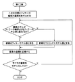
図2には、本実施形態の作成方法のフローチャートが示される。
この作成方法では、マトリックスゴムc及びフィラーdをモデル化して第1の有限要素モデル2A(図6に示す)を作成する第1工程S1、及び図8に示されるマトリックスゴムcをなすマトリックスモデル部4とフィラーdをなすフィラーモデル部5との境界の節点7を含む要素6を変形させた第2の有限要素モデル2Bを作成する第2工程S2を含む。
FIG. 2 shows a flowchart of the creation method of the present embodiment.
In this creation method, the matrix rubber c and the filler d are modeled to create a first
前記第1工程S1では、図3、図5(a)に示されるように、コンピュータ1(図1に示す)が、例えば、予め決定された二次元空間3を格子状に区分する複数の要素6に、予め記憶されているフィラーd(図19に示す)の輪郭9の座標をあてはめて、マトリックスゴムcをなすマトリックスモデル部4、及びフィラーdをなすフィラーモデル部5を各要素6でモデル化し、それらの座標を記憶する。
In the first step S1, as shown in FIGS. 3 and 5A, the computer 1 (shown in FIG. 1), for example, has a plurality of elements that divide the predetermined two-
具体的には、図5(b)に拡大して示されるように、各要素6の中心6cが、フィラーdの輪郭9よりも図5(a)に示されるフィラーdの中心(フィラーdが非円形である場合は図心とし、以下同じである。)10側に配されるものをフィラーモデル部5の要素6とし、それ以外をマトリックスモデル部4の要素6としてモデル化している。
Specifically, as shown in an enlarged view in FIG. 5B, the
これにより、二次元空間3には、図6に示されるように、マトリックスモデル部4とフィラーモデル部5とを含む第1の有限要素モデル2Aが形成される。この例では、理解しやすいように、フィラーモデル部5が着色されて表示される。
Thereby, as shown in FIG. 6, a first
前記二次元空間3は、例えば一辺の長さL1が50〜150nm程度の正方形に形成される。また、本実施形態の要素6は、図5(b)に示されるように、4つの前記節点7と、各節点7、7を間を直線で繋ぐ4本の辺8とで形成され、その一辺の長さL2が0.1〜3nm程度の正方形に形成される。なお、この要素6は、本実施形態のような正方形に限定されるわけではなく、例えば長方形ものでもよい。
The two-
次に、前記第2工程S2では、第1の有限要素モデル2Aにおいて、コンピュータ1が、マトリックスモデル部4とフィラーモデル部5との境界の節点7A(図5(b)に示す)を、フィラーモデル部5の表面の凹凸13(図6に示す)が小さくなる向きに移動させて、該境界の節点7Aを含む要素6を変形させた第2の有限要素モデル2B(図8に示す)を作成する。
Next, in the second step S2, in the first
具体的には、図4、図7(a)に示されるように、コンピュータ1が、フィラーdの中心10(図6に示す)と、各境界の節点7Aとを通る直線11に沿って、境界の節点7Aを、該直線11とフィラーdの輪郭9との交点12へ移動させるのが望ましい。
Specifically, as shown in FIG. 4 and FIG. 7A, the
図7(b)に示されるように、この境界の節点7Aの移動に伴い、境界の節点7Aを含む要素6のみが変形し、図8に示される第2の有限要素モデル2Bが形成される。そして、境界の接点7Aを含む要素6の各座標は、コンピュータ1(図1に示す)に記憶される。
As shown in FIG. 7B, with the movement of the
この第2の有限要素モデル2Bでは、図7(b)に示されるように、境界の節点7A間をのびる辺8が滑らかに連なり、フィラーモデル部5の表面の凹凸13(図6に示す)が小に形成される。一方、境界の節点7Aを含まない要素6は、変形されることなく、第1の有限要素モデル2Aのときと同じ形状(本実施形態では、正方形)が維持されるので、処理時間を大幅に短縮しうる。
In the second
また、第2の有限要素モデル2Bのマトリックスモデル部4及びフィラーモデル部5の各要素6には、シミュレーションによる数値解析に必要な情報が定義される。この数値解析とは、例えば有限要素法等の数値解析法を意味する。また、解析に必要な情報としては、各要素6を構成する節点7の番号や座標値が少なくとも含まれる。
In addition, information necessary for numerical analysis by simulation is defined in each
さらに、各要素6には、各々が代表する部分の材料特性(物性値)などが定義される。即ち、マトリックスモデル部4及びフィラーモデル部5の各要素6には、それぞれ図19に示されるマトリックスゴムc及びフィラーdの物性に応じた材料定数が定義される。そして、これらの情報は、いずれも前記コンピュータ1に記憶される。
Further, each
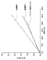
図9には、図19に示されるフィラー配合ゴムbを0〜80%伸長させたときの応力と伸びとの測定結果が破線で示される。また、図9には、本実施形態の第2の有限要素モデル2B(要素数:1600個)を0〜80%伸長させたときの応力と伸びとのシミュレーション結果(実施例1)が実線で示されるとともに、図20(a)に示される正方形の要素eのみでモデル化された有限要素モデルa(要素数:1600個)のシミュレーション結果(比較例1)が二点鎖線で示される。
In FIG. 9, the measurement results of stress and elongation when the filler-containing rubber b shown in FIG. 19 is extended by 0 to 80% are indicated by broken lines. In FIG. 9, the solid line represents the simulation result (Example 1) of stress and elongation when the second
これらの結果より、実施例1は、比較例1に比べてシミュレーション精度を向上しうることが確認できる。これは、実施例1の第2の有限要素モデル2Bが、フィラーモデル部5の表面に形成される凹凸13(図6に示す)を小さくして、滑らかな表面形状に形成できるため、従来のように、フィラーモデル部5に接触するマトリックスモデル部4の剛性が大に見積られることを抑制でき、シミュレーション精度を向上し得たと推察される。
From these results, it can be confirmed that Example 1 can improve the simulation accuracy as compared with Comparative Example 1. This is because the second
なお、図10(a)に示されるように、第2の工程S2において、複数の境界の節点7A、7Aが、同一の前記直線11上に位置する場合、各境界の節点7A、7Aを、直線11とフィラーdの輪郭9との交点12に移動させると、互いに重複する。このような重複は、その境界の節点7Aを含む要素6が、例えば四辺形から三角形へと潰れてしまい、それらの剛性を計算できないおそれがある。
As shown in FIG. 10A, in the second step S2, when a plurality of
このような重複を抑制するために、第2工程S2では、図10、図11に示されるように、コンピュータ1が、境界の節点7Aを交点12に移動させる前に、同一の直線11上で複数の境界の節点7Aが重複するかを確認する工程と、上記工程で重複すると判断された場合の境界の節点7A、7Aと交点12との距離L3、L3をそれぞれ計算して、該距離L3、L3に0よりも大かつ1よりも小の係数を乗じた修正距離で、境界の節点7A、7Aを直線11に沿って交点12側へ移動させる工程がさらに含まれるのが望ましい。これにより、図10(b)に示されるように、境界の節点7Aの重複が抑制され、シミュレーション精度が向上する。
In order to suppress such duplication, in the second step S2, as shown in FIGS. 10 and 11, before the
次に、本発明の他の実施形態の作成方法が示される。
本実施形態の作成方法は、コンピュータ1が、図12に示されるフィラー配合ゴムbの三次元の有限要素モデル20(図17に示す)を用いて作成する方法である。このような有限要素モデル20は、マトリックスゴムcにフィラーdが三次元に分散した三次元構造のモデルを作成できるので、二次元の有限要素モデル2に比べてシミュレーション精度を向上しうる。
Next, a creation method according to another embodiment of the present invention will be described.
How to create the present embodiment, the
この作成方法では、マトリックスゴムc及びフィラーdをそれぞれ、六面体要素24でモデル化して第1の有限要素モデル20A(図15に示す)を作成する第1工程S1、及び六面体要素24を変形させた第2の有限要素モデル20B(図17に示す)を作成する第2工程S2を含む。
In this creation method, the matrix rubber c and the filler d are each modeled with a
前記第1工程S1では、図13に示されるように、コンピュータ1が、例えば、予め決定された三次元空間21を区分する六面体要素24に、予め記憶されている三次元のフィラーd(図12)の輪郭27の座標をあてはめて、マトリックスゴムcをなすマトリックスモデル部22、及びフィラーdをなすフィラーモデル部23を各六面体要素24でモデル化し、それらの座標を記憶する。
In the first step S1, as shown in FIG. 13, the
具体的には、図14に示されるように、各六面体要素24の中心24cがフィラーdの輪郭27の座標よりも、該フィラーdの中心28(図13に示す)側に配されるものをフィラーモデル部23の六面体要素24とし、それ以外をマトリックスモデル部22の六面体要素24としてモデル化している。
Specifically, as shown in FIG. 14, the
これにより、三次元空間21には、図15に示されるように、マトリックスモデル部22とフィラーモデル部23とを含む第1の有限要素モデル20Aが形成される。この例では、理解しやすいように、フィラーモデル部23が着色されて表示される。
As a result, the first
前記三次元空間21は、図13に示されるように、例えば一辺の長さL6が50〜150nm程度の立方体に形成される。また、本実施形態の六面体要素24は、図14に示されるように、8つの節点25と、各節点25、25を間を直線で繋ぐ12本の辺26とで形成され、その一辺の長さL7が0.1〜3nm程度の立方体に形成される。
As shown in FIG. 13, the three-
次に、前記第2工程S2では、図14に示されるように、第1の有限要素モデル20Aにおいて、コンピュータ1が、マトリックスモデル部22とフィラーモデル部23との境界の節点25Aを、フィラーモデル部23の表面の凹凸が小さくなる向きに移動させて、該境界の節点25Aを含む六面体要素24を変形させた第2の有限要素モデル20B(図17に示す)を作成する。
Next, in the second step S2, as shown in FIG. 14, in the first
具体的には、図16(a)、(b)に示されるようにコンピュータ1が、予め記憶されているフィラーdの中心28(図15に示す)と、各境界の節点25Aとを通る直線29において、境界の節点25Aを、該直線29とフィラーdの輪郭27との交点30へ移動させるのが望ましい。
Specifically, as shown in FIGS. 16A and 16B, the
これにより、境界の節点25Aを含む六面体要素24のみが変形し、図17に示されるフィラーモデル部23の表面の凹凸が小に形成された第2の有限要素モデル20Bが形成される。一方、境界の節点25Aを含まない六面体要素24は、変形されることなく、第1の有限要素モデル20Aのときと同じ形状が維持されるので、処理時間を大幅に短縮しうる。そして、第2の有限要素モデル20Bの各マトリックスモデル部22及びフィラーモデル部23の各座標は、コンピュータ1に記憶される。
As a result, only the
また、各六面体要素24には、該六面体要素24を構成する節点25の番号や、節点25の座標値等、シミュレーションによる数値解析に必要な情報や、図12に示されるマトリックスゴムc及びフィラーdの物性に応じた材料定数等が定義され、コンピュータ1に記憶される。
Each
図18には、図12に示されるフィラー配合ゴムbを0〜80%伸長させたときの応力と伸びとの測定結果が破線で示される。また、図18には、本実施形態の第2の有限要素モデル20B(要素数:64000個)を0〜80%伸長させたときの応力と伸びとのシミュレーション結果(実施例2)が実線で示されるとともに、図15に示される第1の有限要素モデル20A(要素数:64000個)のシミュレーション結果(比較例2)が二点鎖線で示される。
In FIG. 18, the measurement results of stress and elongation when the filler-containing rubber b shown in FIG. 12 is extended by 0 to 80% are indicated by broken lines. In FIG. 18, the solid line represents the simulation results (Example 2) of stress and elongation when the second
これらの結果より、実施例1は、比較例1に比べてシミュレーション精度を向上しうることが確認できる。これは、実施例1の第2の有限要素モデル20Bが、フィラーモデル部23の表面に形成される凹凸を小さくできるため、フィラーモデル部23に接触するマトリックスモデル部22の剛性が大に見積られることを抑制でき、シミュレーション精度を向上し得たと推察される。
From these results, it can be confirmed that Example 1 can improve the simulation accuracy as compared with Comparative Example 1. This is because the second
なお、第2の工程S2において、複数の境界の節点25Aが、同一の前記直線29上に位置する場合、前実施形態で説明したように、境界の節点25A、25Aが重複するおそれがある。
In the second step S2, when a plurality of
このような重複を抑制するために、第2工程S2では、前実施形態と同様に、コンピュータ1が、境界の節点25Aを前記交点30に移動させる前に、同一の直線29上で複数の境界の節点25Aが重複するかを確認する工程と、上記工程で重複すると判断された場合の境界の節点25Aと交点30との距離(図示省略)を計算して、該距離に0よりも大かつ1よりも小の係数を乗じた修正距離で直線29に沿って移動させる工程が含まれるのが望ましい。
In order to suppress such duplication, in the second step S2, as in the previous embodiment, the
以上、本発明の特に好ましい実施形態について詳述したが、本発明は図示の実施形態に限定されることなく、種々の態様に変形して実施しうる。 As mentioned above, although especially preferable embodiment of this invention was explained in full detail, this invention is not limited to embodiment of illustration, It can deform | transform and implement in a various aspect.
1 コンピュータ
2 有限要素モデル
4 マトリックスモデル部
5 フィラーモデル部
6 要素
7 節点
b フィラー配合ゴム
c マトリックスゴム
d フィラー
1
Claims (6)
前記マトリックスゴム及び前記フィラーをそれぞれ正方形又は長方形の要素でモデル化して第1の有限要素モデルを作成する第1工程と、
前記第1の有限要素モデルにおいて、前記マトリックスゴムをなすマトリックスモデル部と、前記フィラーをなすフィラーモデル部との境界の節点を、前記フィラーモデル部の表面の凹凸が小さくなる向きに移動させ、該境界の節点を含む前記要素を変形させた第2の有限要素モデルを作成する第2工程とを含み、
前記第2工程は、前記各境界の節点を、該境界の節点と前記フィラーモデル部の中心とを通る直線上で移動させることを特徴とするフィラー配合ゴムの有限要素モデルの作成方法。 Computer, a method for creating a two-dimensional finite element model of the filler-containing rubber fillers are distributed in a substantially circular shape in a matrix rubber,
A first step of modeling the matrix rubber and the filler with square or rectangular elements, respectively, to create a first finite element model;
In the first finite element model, the node of the boundary between the matrix model part forming the matrix rubber and the filler model part forming the filler is moved in a direction in which the unevenness of the surface of the filler model part is reduced, a second step of creating a second finite element model obtained by modifying the element comprising nodes boundary seen including,
The second step is a method for creating a finite element model of a filler-blended rubber , wherein the node of each boundary is moved on a straight line passing through the node of the boundary and the center of the filler model portion .
上記工程で重複すると判断された場合の前記境界の節点に対し、該境界の節点と前記交点との距離を計算して、該距離に0よりも大かつ1よりも小の係数を乗じた修正距離で前記直線上を移動させる工程をさらに含む請求項2に記載のフィラー配合ゴムの有限要素モデルの作成方法。 The second step is a step of confirming whether a plurality of the boundary nodes overlap on the same straight line; and
A correction by calculating the distance between the boundary node and the intersection, and multiplying the distance by a coefficient larger than 0 and smaller than 1 for the boundary node when it is determined that the above process overlaps The method for creating a finite element model of filler-containing rubber according to claim 2, further comprising a step of moving on the straight line by a distance .
前記マトリックスゴム及び前記フィラーをそれぞれ六面体要素でモデル化して第1の有限要素モデルを作成する第1工程と、
前記第1の有限要素モデルにおいて、前記マトリックスゴムをなすマトリックスモデル部と、前記フィラーをなすフィラーモデル部との境界の節点を、前記フィラーモデル部の表面の凹凸が小さくなる向きに移動させ、該境界の節点を含む六面体要素を変形させた第2の有限要素モデルを作成する第2工程とを含み、
前記第2工程は、前記各境界の節点を、該境界の節点と前記フィラーモデル部の中心とを通る直線上で移動させることを特徴とするフィラー配合ゴムの有限要素モデルの作成方法。 A computer is a method for creating a three-dimensional finite element model of filler-containing rubber in which fillers having a substantially spherical shape are dispersed in matrix rubber,
A first step of modeling the matrix rubber and the filler with hexahedral elements to create a first finite element model;
In the first finite element model, the node of the boundary between the matrix model part forming the matrix rubber and the filler model part forming the filler is moved in a direction in which the unevenness of the surface of the filler model part is reduced, A second step of creating a second finite element model in which a hexahedral element including a boundary node is deformed,
The second step is a method for creating a finite element model of a filler-blended rubber , wherein the node of each boundary is moved on a straight line passing through the node of the boundary and the center of the filler model portion .
上記工程で重複すると判断された場合の前記境界の節点に対し、該境界の節点と前記交点との距離を計算して、該距離に0よりも大かつ1よりも小の係数を乗じた修正距離で前記直線上を移動させる工程をさらに含む請求項5に記載のフィラー配合ゴムの有限要素モデルの作成方法。 The second step is a step of confirming whether a plurality of the boundary nodes overlap on the same straight line; and
A correction by calculating the distance between the boundary node and the intersection, and multiplying the distance by a coefficient larger than 0 and smaller than 1 for the boundary node when it is determined that the above process overlaps The method for creating a finite element model of filler-containing rubber according to claim 5 , further comprising a step of moving on the straight line by a distance .
Priority Applications (3)
| Application Number | Priority Date | Filing Date | Title |
|---|---|---|---|
| JP2011049309A JP5186015B2 (en) | 2011-03-07 | 2011-03-07 | How to create a finite element model of filler compounded rubber |
| US13/288,068 US8768661B2 (en) | 2011-03-07 | 2011-11-03 | Method for creating finite element model of rubber composite |
| EP11010065A EP2498192A3 (en) | 2011-03-07 | 2011-12-21 | Method for creating finite element model of rubber composite |
Applications Claiming Priority (1)
| Application Number | Priority Date | Filing Date | Title |
|---|---|---|---|
| JP2011049309A JP5186015B2 (en) | 2011-03-07 | 2011-03-07 | How to create a finite element model of filler compounded rubber |
Publications (2)
| Publication Number | Publication Date |
|---|---|
| JP2012185733A JP2012185733A (en) | 2012-09-27 |
| JP5186015B2 true JP5186015B2 (en) | 2013-04-17 |
Family
ID=45445721
Family Applications (1)
| Application Number | Title | Priority Date | Filing Date |
|---|---|---|---|
| JP2011049309A Active JP5186015B2 (en) | 2011-03-07 | 2011-03-07 | How to create a finite element model of filler compounded rubber |
Country Status (3)
| Country | Link |
|---|---|
| US (1) | US8768661B2 (en) |
| EP (1) | EP2498192A3 (en) |
| JP (1) | JP5186015B2 (en) |
Families Citing this family (10)
| Publication number | Priority date | Publication date | Assignee | Title |
|---|---|---|---|---|
| JP2013057638A (en) * | 2011-09-09 | 2013-03-28 | Sumitomo Rubber Ind Ltd | Simulation method for rubber materials |
| JP5395864B2 (en) * | 2011-09-14 | 2014-01-22 | 住友ゴム工業株式会社 | Rubber material simulation method |
| JP6030986B2 (en) * | 2013-04-01 | 2016-11-24 | 住友ゴム工業株式会社 | Rubber material contact simulation method |
| JP6294613B2 (en) * | 2013-09-11 | 2018-03-14 | 住友ゴム工業株式会社 | Method for simulating polymer materials |
| KR102262622B1 (en) | 2013-10-07 | 2021-06-08 | 스미토모 고무 코교 카부시키카이샤 | Method for creating finite element model for filler-containing rubber |
| JP5913260B2 (en) * | 2013-11-14 | 2016-04-27 | 住友ゴム工業株式会社 | Method for simulating polymer materials |
| EP3502931B1 (en) | 2017-12-24 | 2023-03-15 | Dassault Systèmes | Designing a part by topology optimization |
| EP3503040A1 (en) * | 2017-12-24 | 2019-06-26 | Dassault Systèmes | Design of a 3d finite element mesh of a 3d part that comprises a lattice structure |
| CN109800494B (en) * | 2019-01-14 | 2023-02-17 | 湖南大学 | Vehicle body forward conceptual design method based on thin-wall section attribute |
| CN110765690B (en) * | 2019-11-05 | 2024-02-02 | 上海波客实业有限公司 | Rubber structure seal analysis method |
Family Cites Families (8)
| Publication number | Priority date | Publication date | Assignee | Title |
|---|---|---|---|---|
| JPH1125293A (en) * | 1997-07-02 | 1999-01-29 | Hitachi Ltd | Mesh creating method |
| JPH11283050A (en) * | 1998-03-31 | 1999-10-15 | Mitsubishi Electric Corp | Method for generating finite element data and device therefor |
| JP2004110212A (en) * | 2002-09-13 | 2004-04-08 | Sumitomo Metal Ind Ltd | Method and device for generating hexahedron mesh, method and device for analyzing transformation of solid object, computer program, and recording medium |
| JP2005351770A (en) | 2004-06-10 | 2005-12-22 | Sumitomo Rubber Ind Ltd | Simulation method for rubber material |
| JP4602929B2 (en) | 2006-03-30 | 2010-12-22 | 株式会社ブリヂストン | Rubber material deformation behavior prediction apparatus and rubber material deformation behavior prediction method |
| JP5169279B2 (en) | 2008-02-14 | 2013-03-27 | 横浜ゴム株式会社 | Method of operating heterogeneous material model creation apparatus, method of operating heterogeneous material simulation apparatus using this method, heterogeneous material model creation apparatus, and heterogeneous material simulation apparatus |
| JP2009276147A (en) | 2008-05-13 | 2009-11-26 | Sumitomo Rubber Ind Ltd | Creation method of analytical model of filler-filled rubber |
| JP5324820B2 (en) * | 2008-05-19 | 2013-10-23 | 住友ゴム工業株式会社 | How to create an analysis model |
-
2011
- 2011-03-07 JP JP2011049309A patent/JP5186015B2/en active Active
- 2011-11-03 US US13/288,068 patent/US8768661B2/en active Active
- 2011-12-21 EP EP11010065A patent/EP2498192A3/en not_active Ceased
Also Published As
| Publication number | Publication date |
|---|---|
| EP2498192A3 (en) | 2012-10-31 |
| US20120232848A1 (en) | 2012-09-13 |
| EP2498192A2 (en) | 2012-09-12 |
| US8768661B2 (en) | 2014-07-01 |
| JP2012185733A (en) | 2012-09-27 |
Similar Documents
| Publication | Publication Date | Title |
|---|---|---|
| JP5186015B2 (en) | How to create a finite element model of filler compounded rubber | |
| JP5923069B2 (en) | Method for simulating polymer materials | |
| JP6294613B2 (en) | Method for simulating polymer materials | |
| JP6353290B2 (en) | Polymer material model creation method | |
| JP5324820B2 (en) | How to create an analysis model | |
| US9117307B2 (en) | Method for creating finite element model of rubber composite | |
| JP6166639B2 (en) | How to create a composite simulation model | |
| KR102262622B1 (en) | Method for creating finite element model for filler-containing rubber | |
| JP5503618B2 (en) | Rubber material simulation method | |
| JP6152003B2 (en) | How to create a tire model | |
| JP6050704B2 (en) | How to create a simulation model | |
| JP5806169B2 (en) | Design data generation apparatus, generation method thereof, and program | |
| JP2015118475A (en) | Method for creating finite element model of filler blending rubber | |
| JP6743570B2 (en) | How to create a polymer material model | |
| JP5180735B2 (en) | Rubber material simulation method | |
| JP2014059621A (en) | Analysis device and analysis method | |
| KR20140147761A (en) | Designing a folded sheet object | |
| JP2019109696A (en) | Rubber material model preparation method and simulation method | |
| JP5994464B2 (en) | Metal pipe analysis method | |
| JP2015162236A (en) | Method for creating filler compounded rubber model | |
| JP6415835B2 (en) | Draw model generation method and draw model generation system | |
| JP6170400B2 (en) | How to create a finite element model of filler compounded rubber | |
| JP2009276147A (en) | Creation method of analytical model of filler-filled rubber | |
| JP2017138910A (en) | Creation method of filler blending rubber model | |
| JP6144612B2 (en) | Draw model generation method and draw model generation system |
Legal Events
| Date | Code | Title | Description |
|---|---|---|---|
| A131 | Notification of reasons for refusal |
Free format text: JAPANESE INTERMEDIATE CODE: A131 Effective date: 20121106 |
|
| A521 | Request for written amendment filed |
Free format text: JAPANESE INTERMEDIATE CODE: A523 Effective date: 20121214 |
|
| TRDD | Decision of grant or rejection written | ||
| A01 | Written decision to grant a patent or to grant a registration (utility model) |
Free format text: JAPANESE INTERMEDIATE CODE: A01 Effective date: 20130115 |
|
| A61 | First payment of annual fees (during grant procedure) |
Free format text: JAPANESE INTERMEDIATE CODE: A61 Effective date: 20130118 |
|
| R150 | Certificate of patent or registration of utility model |
Ref document number: 5186015 Country of ref document: JP Free format text: JAPANESE INTERMEDIATE CODE: R150 Free format text: JAPANESE INTERMEDIATE CODE: R150 |
|
| FPAY | Renewal fee payment (event date is renewal date of database) |
Free format text: PAYMENT UNTIL: 20160125 Year of fee payment: 3 |
|
| R250 | Receipt of annual fees |
Free format text: JAPANESE INTERMEDIATE CODE: R250 |
|
| R250 | Receipt of annual fees |
Free format text: JAPANESE INTERMEDIATE CODE: R250 |
|
| R250 | Receipt of annual fees |
Free format text: JAPANESE INTERMEDIATE CODE: R250 |
|
| R250 | Receipt of annual fees |
Free format text: JAPANESE INTERMEDIATE CODE: R250 |
|
| R250 | Receipt of annual fees |
Free format text: JAPANESE INTERMEDIATE CODE: R250 |
|
| R250 | Receipt of annual fees |
Free format text: JAPANESE INTERMEDIATE CODE: R250 |
|
| R250 | Receipt of annual fees |
Free format text: JAPANESE INTERMEDIATE CODE: R250 |
|
| R250 | Receipt of annual fees |
Free format text: JAPANESE INTERMEDIATE CODE: R250 |
|
| R250 | Receipt of annual fees |
Free format text: JAPANESE INTERMEDIATE CODE: R250 |