JP5185273B2 - In-column cell featuring improved drug distribution and stent support - Google Patents
In-column cell featuring improved drug distribution and stent support Download PDFInfo
- Publication number
- JP5185273B2 JP5185273B2 JP2009527393A JP2009527393A JP5185273B2 JP 5185273 B2 JP5185273 B2 JP 5185273B2 JP 2009527393 A JP2009527393 A JP 2009527393A JP 2009527393 A JP2009527393 A JP 2009527393A JP 5185273 B2 JP5185273 B2 JP 5185273B2
- Authority
- JP
- Japan
- Prior art keywords
- strut
- stent
- segment
- struts
- icc
- Prior art date
- Legal status (The legal status is an assumption and is not a legal conclusion. Google has not performed a legal analysis and makes no representation as to the accuracy of the status listed.)
- Expired - Fee Related
Links
Images


Classifications
-
- A—HUMAN NECESSITIES
- A61—MEDICAL OR VETERINARY SCIENCE; HYGIENE
- A61F—FILTERS IMPLANTABLE INTO BLOOD VESSELS; PROSTHESES; DEVICES PROVIDING PATENCY TO, OR PREVENTING COLLAPSING OF, TUBULAR STRUCTURES OF THE BODY, e.g. STENTS; ORTHOPAEDIC, NURSING OR CONTRACEPTIVE DEVICES; FOMENTATION; TREATMENT OR PROTECTION OF EYES OR EARS; BANDAGES, DRESSINGS OR ABSORBENT PADS; FIRST-AID KITS
- A61F2/00—Filters implantable into blood vessels; Prostheses, i.e. artificial substitutes or replacements for parts of the body; Appliances for connecting them with the body; Devices providing patency to, or preventing collapsing of, tubular structures of the body, e.g. stents
- A61F2/82—Devices providing patency to, or preventing collapsing of, tubular structures of the body, e.g. stents
- A61F2/86—Stents in a form characterised by the wire-like elements; Stents in the form characterised by a net-like or mesh-like structure
- A61F2/90—Stents in a form characterised by the wire-like elements; Stents in the form characterised by a net-like or mesh-like structure characterised by a net-like or mesh-like structure
- A61F2/91—Stents in a form characterised by the wire-like elements; Stents in the form characterised by a net-like or mesh-like structure characterised by a net-like or mesh-like structure made from perforated sheet material or tubes, e.g. perforated by laser cuts or etched holes
- A61F2/915—Stents in a form characterised by the wire-like elements; Stents in the form characterised by a net-like or mesh-like structure characterised by a net-like or mesh-like structure made from perforated sheet material or tubes, e.g. perforated by laser cuts or etched holes with bands having a meander structure, adjacent bands being connected to each other
- A61F2002/9155—Adjacent bands being connected to each other
- A61F2002/91558—Adjacent bands being connected to each other connected peak to peak
-
- A—HUMAN NECESSITIES
- A61—MEDICAL OR VETERINARY SCIENCE; HYGIENE
- A61F—FILTERS IMPLANTABLE INTO BLOOD VESSELS; PROSTHESES; DEVICES PROVIDING PATENCY TO, OR PREVENTING COLLAPSING OF, TUBULAR STRUCTURES OF THE BODY, e.g. STENTS; ORTHOPAEDIC, NURSING OR CONTRACEPTIVE DEVICES; FOMENTATION; TREATMENT OR PROTECTION OF EYES OR EARS; BANDAGES, DRESSINGS OR ABSORBENT PADS; FIRST-AID KITS
- A61F2/00—Filters implantable into blood vessels; Prostheses, i.e. artificial substitutes or replacements for parts of the body; Appliances for connecting them with the body; Devices providing patency to, or preventing collapsing of, tubular structures of the body, e.g. stents
- A61F2/82—Devices providing patency to, or preventing collapsing of, tubular structures of the body, e.g. stents
- A61F2/86—Stents in a form characterised by the wire-like elements; Stents in the form characterised by a net-like or mesh-like structure
- A61F2/90—Stents in a form characterised by the wire-like elements; Stents in the form characterised by a net-like or mesh-like structure characterised by a net-like or mesh-like structure
- A61F2/91—Stents in a form characterised by the wire-like elements; Stents in the form characterised by a net-like or mesh-like structure characterised by a net-like or mesh-like structure made from perforated sheet material or tubes, e.g. perforated by laser cuts or etched holes
- A61F2/915—Stents in a form characterised by the wire-like elements; Stents in the form characterised by a net-like or mesh-like structure characterised by a net-like or mesh-like structure made from perforated sheet material or tubes, e.g. perforated by laser cuts or etched holes with bands having a meander structure, adjacent bands being connected to each other
- A61F2002/9155—Adjacent bands being connected to each other
- A61F2002/91575—Adjacent bands being connected to each other connected peak to trough
-
- A—HUMAN NECESSITIES
- A61—MEDICAL OR VETERINARY SCIENCE; HYGIENE
- A61F—FILTERS IMPLANTABLE INTO BLOOD VESSELS; PROSTHESES; DEVICES PROVIDING PATENCY TO, OR PREVENTING COLLAPSING OF, TUBULAR STRUCTURES OF THE BODY, e.g. STENTS; ORTHOPAEDIC, NURSING OR CONTRACEPTIVE DEVICES; FOMENTATION; TREATMENT OR PROTECTION OF EYES OR EARS; BANDAGES, DRESSINGS OR ABSORBENT PADS; FIRST-AID KITS
- A61F2220/00—Fixations or connections for prostheses classified in groups A61F2/00 - A61F2/26 or A61F2/82 or A61F9/00 or A61F11/00 or subgroups thereof
- A61F2220/0025—Connections or couplings between prosthetic parts, e.g. between modular parts; Connecting elements
- A61F2220/005—Connections or couplings between prosthetic parts, e.g. between modular parts; Connecting elements using adhesives
-
- A—HUMAN NECESSITIES
- A61—MEDICAL OR VETERINARY SCIENCE; HYGIENE
- A61F—FILTERS IMPLANTABLE INTO BLOOD VESSELS; PROSTHESES; DEVICES PROVIDING PATENCY TO, OR PREVENTING COLLAPSING OF, TUBULAR STRUCTURES OF THE BODY, e.g. STENTS; ORTHOPAEDIC, NURSING OR CONTRACEPTIVE DEVICES; FOMENTATION; TREATMENT OR PROTECTION OF EYES OR EARS; BANDAGES, DRESSINGS OR ABSORBENT PADS; FIRST-AID KITS
- A61F2220/00—Fixations or connections for prostheses classified in groups A61F2/00 - A61F2/26 or A61F2/82 or A61F9/00 or A61F11/00 or subgroups thereof
- A61F2220/0025—Connections or couplings between prosthetic parts, e.g. between modular parts; Connecting elements
- A61F2220/0058—Connections or couplings between prosthetic parts, e.g. between modular parts; Connecting elements soldered or brazed or welded
-
- A—HUMAN NECESSITIES
- A61—MEDICAL OR VETERINARY SCIENCE; HYGIENE
- A61F—FILTERS IMPLANTABLE INTO BLOOD VESSELS; PROSTHESES; DEVICES PROVIDING PATENCY TO, OR PREVENTING COLLAPSING OF, TUBULAR STRUCTURES OF THE BODY, e.g. STENTS; ORTHOPAEDIC, NURSING OR CONTRACEPTIVE DEVICES; FOMENTATION; TREATMENT OR PROTECTION OF EYES OR EARS; BANDAGES, DRESSINGS OR ABSORBENT PADS; FIRST-AID KITS
- A61F2230/00—Geometry of prostheses classified in groups A61F2/00 - A61F2/26 or A61F2/82 or A61F9/00 or A61F11/00 or subgroups thereof
- A61F2230/0002—Two-dimensional shapes, e.g. cross-sections
- A61F2230/0028—Shapes in the form of latin or greek characters
- A61F2230/0054—V-shaped
-
- A—HUMAN NECESSITIES
- A61—MEDICAL OR VETERINARY SCIENCE; HYGIENE
- A61F—FILTERS IMPLANTABLE INTO BLOOD VESSELS; PROSTHESES; DEVICES PROVIDING PATENCY TO, OR PREVENTING COLLAPSING OF, TUBULAR STRUCTURES OF THE BODY, e.g. STENTS; ORTHOPAEDIC, NURSING OR CONTRACEPTIVE DEVICES; FOMENTATION; TREATMENT OR PROTECTION OF EYES OR EARS; BANDAGES, DRESSINGS OR ABSORBENT PADS; FIRST-AID KITS
- A61F2250/00—Special features of prostheses classified in groups A61F2/00 - A61F2/26 or A61F2/82 or A61F9/00 or A61F11/00 or subgroups thereof
- A61F2250/0058—Additional features; Implant or prostheses properties not otherwise provided for
- A61F2250/0067—Means for introducing or releasing pharmaceutical products into the body
- A61F2250/0068—Means for introducing or releasing pharmaceutical products into the body the pharmaceutical product being in a reservoir
Landscapes
- Health & Medical Sciences (AREA)
- Engineering & Computer Science (AREA)
- Biomedical Technology (AREA)
- Heart & Thoracic Surgery (AREA)
- Life Sciences & Earth Sciences (AREA)
- Cardiology (AREA)
- Oral & Maxillofacial Surgery (AREA)
- Transplantation (AREA)
- Physics & Mathematics (AREA)
- Vascular Medicine (AREA)
- Optics & Photonics (AREA)
- Animal Behavior & Ethology (AREA)
- General Health & Medical Sciences (AREA)
- Public Health (AREA)
- Veterinary Medicine (AREA)
- Media Introduction/Drainage Providing Device (AREA)
- Prostheses (AREA)
Description
本発明は、ステント等の埋め込み型医療機器、その製造、送出、及び使用方法に関する。 The present invention relates to an implantable medical device, such as a stent, and methods for manufacturing, delivering, and using the same.
ステントは、生体の管腔に挿入される医療機器である。一般的に、ステントは、血管内の狭窄又は動脈瘤の部位に、管腔内的に、即ち所謂「最小侵襲技術」によって埋め込まれ、そこでは、ステントは半径方向に小さくされた形態、任意でシース及び/又はカテーテルによって半径方向に圧縮させられた形態にあり、ステント送出システムによって送出され、即ち必要とされる部位へ「挿入」させられる。導入器は、例えば患者の皮膚を通り、即ち「切開技術」によって、生体の外側の接近位置から生体に入り、入口血管は小さな手術手段によって露出させられる。 A stent is a medical device that is inserted into the lumen of a living body. In general, stents are implanted intraluminally, ie by so-called “minimally invasive techniques”, at the site of a stenosis or aneurysm in a blood vessel, where the stent is in a radially reduced form, optionally It is in a radially compressed configuration by the sheath and / or catheter and is delivered by the stent delivery system, ie “inserted” into the required site. The introducer passes through the skin of the patient, for example, by an “incision technique”, entering the living body from an access position outside the living body, and the inlet blood vessel is exposed by small surgical means.
ステント、グラフト、ステント‐グラフト、大静脈フィルタ、膨張フレームワーク、及び同様な埋め込み型医療機器は、以下集合的にステントと呼ばれ、一般的には経皮的に埋め込まれ得ると共に、経皮的に挿入された後に半径方向に拡張させられる血管内インプラントである半径方向に拡張する内部人口器官である。ステントは、血管システム、尿路、胆道、ファロビウス管、冠状血管、二次血管等の様々な生体管腔又は血管に埋め込まれ得る。それらは自己拡張的であってよく、バルーンに据え付けられた時等の内部半径方向力によって拡張させられ、又は自己拡張及びバルーン拡張の組み合わせ(ハイブリッド拡張)であってよい。バルーン拡張ステントの例は、特許文献1に示されている。自己拡張ステントの例は、特許文献2に記載されている。 Stents, grafts, stent-grafts, vena cava filters, inflation frameworks, and similar implantable medical devices are hereinafter collectively referred to as stents and are generally percutaneously implantable and transcutaneous. It is a radially expanding internal prosthetic organ that is an intravascular implant that is radially expanded after being inserted into. Stents can be implanted in various biological lumens or blood vessels such as vascular systems, urinary tracts, biliary tracts, Farobius tubes, coronary vessels, secondary vessels and the like. They can be self-expanding, expanded by internal radial forces, such as when installed on a balloon, or a combination of self-expanding and balloon expansion (hybrid expansion). An example of a balloon expandable stent is shown in US Pat. An example of a self-expanding stent is described in US Pat.
ステントは、管状原料から、又は切断又はエッチングが行われ、続いて巻回される平坦状シートから、又は1個又は複数の編み合わせられたワイヤ又は組紐からの設計物を切断又はエッチングする工程を含む方法によって作られてよい。 Stent is a process of cutting or etching a design from a tubular material or from a flat sheet that is cut or etched and subsequently wound or from one or more knitted wires or braids. It may be made by a method involving.
拡張状態において、適切な支え及び薬剤の送達をもたらす一方で、また非拡張状態において、クリンプ性及び柔軟性並びに送出性を可能にするステントの型に対する必要性がある。 There is a need for a type of stent that provides adequate support and drug delivery in the expanded state, while also allowing crimpability and flexibility and delivery in the unexpanded state.
上記に言及され及び/又は説明される分野は、本明細書に言及されるあらゆる特許、出版物、又は他の情報が、本発明に対して「従来技術」であることを容認するように意図されない。また、本段落は、調査がなされた、又は連邦規則集37の1.56(a)項に規定されるような他の関連情報が存在することを意味すると解釈されるべきではない。 The fields referred to and / or described above are intended to permit any patent, publication, or other information referred to herein to be “prior art” to the present invention. Not. Also, this paragraph should not be construed to mean that there has been any other relevant information that has been investigated or as provided in paragraph 1.56 (a) of Federal Regulations 37.
本願のいずれかで言及される全ての米国特許及び出願、並びに他の出版された文献は、言及されることにより、その全体が本明細書に組み入れられる。
本発明の範囲を制限することなく、本発明の幾つかの請求実施形態の要約が、以下に記載される。本発明の要約された実施形態の付加的な詳細、及び/又は本発明の付加的な実
施形態は、以下の本発明の詳細な説明に見られる。
All U.S. patents and applications, as well as other published literature, mentioned in any of the present application are hereby incorporated by reference in their entirety.
Without limiting the scope of the invention, a summary of several claimed embodiments of the invention is set forth below. Additional details of the summarized embodiments of the invention and / or additional embodiments of the invention may be found in the detailed description of the invention that follows.
本発明は、複数の軸方向に間隔があけられた蛇状帯を有するステントに向けられており、各蛇状帯は、ステントの長手軸の周りに円周方向に配向される軸を有する。蛇状帯は、蛇状帯の軸に沿って間隔があけられた複数のストラットを有し、交互に並ぶ頂及び谷を形成する。蛇状帯は、複数の相互連結ストラットを介して相互に連結されて、軸方向に隣接する蛇状帯及び円周方向に隣接する相互連結ストラットによって画定される複数のセルを形成する。ステントがその非拡張状態にある時に、各蛇状帯は、蛇状帯の内部に複数のスリットを含み、各スリットは、非直線的であると共に、第1端から第2端まで連続する。ステントのその拡張状態への拡張に際して、スリット各々は、コラム内セル(ICC)を形成するために、寸法が拡張する。 The present invention is directed to a stent having a plurality of axially spaced serpentine bands, each serpentine band having an axis oriented circumferentially about the longitudinal axis of the stent. The serpentine band has a plurality of struts spaced along the axis of the serpentine band to form alternating tops and valleys. The serpentine bands are interconnected via a plurality of interconnecting struts to form a plurality of cells defined by axially adjacent serpentine bands and circumferentially adjacent interconnecting struts. When the stent is in its unexpanded state, each serpentine band includes a plurality of slits within the serpentine band, each slit being non-linear and continuing from the first end to the second end. Upon expansion of the stent to its expanded state, each slit expands in size to form an in-column cell (ICC).
本発明の幾つかの実施形態において、各スリットは、その第1端から第2端まで、3個の連続連結されたストラット各々の少なくとも一部に形成される。
幾つかの実施形態において、スリットは、蛇状帯の3個の連続連結ストラットに形成される。3個の連結ストラットは、第1ストラット、第2ストラット、及び第3ストラットを含む。第1、第2、及び第3ストラット各々は、第1端及び第2端を有する。第1ストラットの第2端は、第2ストラットの第1端に連結され、また第2ストラットの第2端は、第3ストラットの第1端に連結される。スリットの第1端は、第1ストラットに位置決めされると共に、スリットの第2端は、第3ストラットに位置決めされる。
In some embodiments of the invention, each slit is formed in at least a portion of each of three consecutively connected struts from its first end to its second end.
In some embodiments, the slit is formed in three consecutively connected struts of the serpentine band. The three connecting struts include a first strut, a second strut, and a third strut. Each of the first, second, and third struts has a first end and a second end. The second end of the first strut is connected to the first end of the second strut, and the second end of the second strut is connected to the first end of the third strut. The first end of the slit is positioned on the first strut, and the second end of the slit is positioned on the third strut.
幾つかの実施形態において、3個の連続ストラットのスリットは、蛇状帯の軸を少なくとも2回交差する。幾つかの実施形態において、スリットは蛇状帯の軸を3回交差する。
幾つかの実施形態において、スリットは、蛇状帯の3個の連続連結ストラットに形成される。3個の連結ストラットは、第1ストラット、第2ストラット、及び第3ストラットを含む。第1、第2及び第3ストラット各々は、第1セグメント及び第2セグメントを有しており、スリットは、第1、第2及び第3ストラット各々の第1セグメント及び第2セグメントを隔てる。
In some embodiments, three continuous strut slits intersect the axis of the serpentine band at least twice. In some embodiments, the slit intersects the axis of the serpentine band three times.
In some embodiments, the slit is formed in three consecutively connected struts of the serpentine band. The three connecting struts include a first strut, a second strut, and a third strut. Each of the first, second, and third struts has a first segment and a second segment, and the slit separates the first segment and the second segment of each of the first, second, and third struts.
幾つかの実施形態において、第1ストラットの第1セグメントは、第2ストラットの第1セグメントに連結されて谷を形成し、第2ストラットの第1セグメントは、第3ストラットの第1セグメントに連結されて頂を形成し、第1ストラットの第2セグメントは、第2ストラットの第2セグメントに連結されて頂を形成し、第2ストラットの第2セグメントは、第3ストラットの第2セグメントに連結されて谷を形成する。 In some embodiments, the first segment of the first strut is connected to the first segment of the second strut to form a valley, and the first segment of the second strut is connected to the first segment of the third strut. The second segment of the first strut is connected to the second segment of the second strut to form the apex, and the second segment of the second strut is connected to the second segment of the third strut To form a valley.
本発明の幾つかの実施形態において、ステントのその拡張状態への拡張に際して、スリット各々は、コラム内セル(ICC)を形成するように、寸法が拡張する。ICCはほぼ多角形であると共に、少なくとも2個の内優角を有する。幾つかの実施形態において、ICCは少なくとも2個の内鋭角を有する。幾つかの実施形態において、ICCは、180度未満の少なくとも4個の内角を有する。 In some embodiments of the invention, upon expansion of the stent to its expanded state, each slit expands in size to form an in-column cell (ICC). The ICC is substantially polygonal and has at least two internal dominant angles. In some embodiments, the ICC has at least two internal acute angles. In some embodiments, the ICC has at least four interior angles less than 180 degrees.
幾つかの実施形態において、第1、第2、及び第3ストラットの第1及び第2セグメントは、ICCを画定し、また第1ストラットの第1セグメントは、ほぼ第3ストラットの第2セグメントと平行である。幾つかの実施形態において、第1ストラットの第2セグメントは、ほぼ第3ストラットの第1セグメントと平行である。幾つかの実施形態において、第2ストラットの第1セグメントは、ほぼ第2ストラットの第2セグメントと平行である。 In some embodiments, the first and second segments of the first, second, and third struts define an ICC, and the first segment of the first strut is approximately the second segment of the third strut. Parallel. In some embodiments, the second segment of the first strut is substantially parallel to the first segment of the third strut. In some embodiments, the first segment of the second strut is substantially parallel to the second segment of the second strut.
幾つかの実施形態において、第1ストラットの第2セグメント及び第3ストラットの第
1セグメントは、第1ストラットの第1セグメント及び第3ストラットの第2セグメントよりも大きい幅を有する。幾つかの実施形態において、第2ストラットの第1セグメント及び第2セグメントは、その長さに沿って幅が変化してよい。
In some embodiments, the second segment of the first strut and the first segment of the third strut have a greater width than the first segment of the first strut and the second segment of the third strut. In some embodiments, the first and second segments of the second strut may vary in width along their length.
蛇状帯はまた、複数の主要ヒンジ点を含んでよく、ステントの拡張及びICCの形成に際して、第1、第2、及び第3ストラットの第1及び第2セグメントは、主要ヒンジ点の周りで回転して、ICCを形成するように、スリットの寸法が増加する。幾つかの実施形態において、第1主要ヒンジ点は、第2ストラットの第1セグメントの端部に配置されており、第2ストラットの第1セグメント及び第3ストラットの第1セグメントは、第1主要ヒンジ点の周りを枢転する。第2主要ヒンジ点は、第2ストラットの第2セグメントの端部に配置されており、第2ストラットの第2セグメント及び第1ストラットの第2セグメントは、第2主要ヒンジ点の周りを枢転する。また、6個の主要ヒンジ点があってもよい。 The serpentine band may also include a plurality of major hinge points, and upon expansion of the stent and formation of the ICC, the first and second segments of the first, second, and third struts are around the major hinge points. The dimensions of the slit increase to rotate to form the ICC. In some embodiments, the first primary hinge point is located at the end of the first segment of the second strut, and the first segment of the second strut and the first segment of the third strut are the first primary Rotate around the hinge point. The second major hinge point is located at the end of the second segment of the second strut, and the second segment of the second strut and the second segment of the first strut pivot about the second major hinge point. To do. There may also be six main hinge points.
幾つかの実施形態において、ステントの少なくとも一部は、治療薬の送達のための1個又は複数の機構を含むように形成される。しばしば、治療薬は、ステントの表面領域に載置される材料のコーティング又は他の層(又は複数の層)の形態をなすと共に、ステントの埋設部位又はそれに隣接する領域で開放させられるように適合される。治療及び/又は高分子コーティングは、1個又は複数の非遺伝子治療薬、遺伝子材料及び細胞、並びにそれらの組み合わせを含んでよい。 In some embodiments, at least a portion of the stent is formed to include one or more mechanisms for delivery of a therapeutic agent. Often, the therapeutic agent is in the form of a coating or other layer (or layers) of material that rests on the surface area of the stent and is adapted to be released at or near the site of implantation of the stent. Is done. The therapeutic and / or polymeric coating may include one or more non-gene therapy agents, genetic material and cells, and combinations thereof.
幾つかの実施形態において、本発明のステントの実施形態は、ステント送出カテーテルに据え付けられる。本発明はまた、開示される本発明のステントを、生体の血管の目的部位へ送出する方法を更に含む。 In some embodiments, the stent embodiments of the present invention are mounted on a stent delivery catheter. The invention also includes a method of delivering the disclosed stent of the invention to a target site in a living blood vessel.
本発明を特徴づけるこれら及び他の実施形態は、本明細書に添付されると共に、その一部を形成する請求項に詳細に示される。しかしながら、本発明、その効果、並びにその使用によって得られる目的の更なる理解のために、本明細書の別の部分を形成する図面、及び付随する説明事項が参照されるべきであり、その中で、本発明の実施形態が例示及び説明される。 These and other embodiments which characterize the invention are pointed out with particularity in the claims annexed hereto and forming a part hereof. However, for further understanding of the present invention, its advantages, and the objects obtained by its use, reference should be made to the drawings that form another part of this specification, and the accompanying descriptions. Embodiments of the present invention will now be illustrated and described.
本発明の詳細な説明が、図面が特定に参照されつつ、以下に説明される。 The detailed description of the invention is described below with particular reference to the drawings.
本発明は多様な形態で具体化されてよいが、本明細書では、本発明の特定の実施形態が詳細に説明される。本説明は、本発明の原理の例証であり、本発明を例証される特定の実施形態に限定するように意図されていない。 While this invention may be embodied in many different forms, there are described in detail herein specific embodiments of the invention. This description is an exemplification of the principles of the invention and is not intended to limit the invention to the particular embodiments illustrated.
本開示のために、図面において同じ符号は、他に指示されていなければ、同じ特徴について言及している。
図面には、本発明の様々な態様が図示されている。一つの図面に図示される要素は、必要に応じて、別の図面に図示される要素と組み合わされ、或いは置き換えられてよい。
For the purposes of this disclosure, like reference numerals in the figures refer to like features unless otherwise indicated.
In the drawings, various aspects of the invention are shown. Elements shown in one drawing may be combined or replaced with elements shown in another drawing as required.
一実施形態において、図1に示すように、本発明は、概して10で示され、末端12及び先端14を有するステントに向けられており、また複数の軸方向に間隔があけられた蛇状帯18を含む。各蛇状帯18は、管状形状に成形されており、複数の拡張コラム19を形成する。各蛇状帯18、ひいては各拡張コラム19は、複数の相互連結ストラット20を介して、長手方向に隣接する蛇状帯18と連結される。図示される相互連結ストラットは、ほぼ同じ長さを有すると共に、一定のパターンで配置される。しかし当然のことながら、相互連結ストラット20は、デザイン、数、長さ、及びパターンが変更してもよい。
In one embodiment, as shown in FIG. 1, the present invention is generally directed at a
複数のセル31が、長手方向に隣接する蛇状帯18、及び円周方向に隣接する相互連結ストラット20によって画定される。当然のことながら、セルの形状は変更してもよく、またセルのパターンは一定又は不揃いであってよい。
A plurality of cells 31 are defined by longitudinally adjacent
蛇状帯18は、ステント10の長手軸24の周りに円周方向に配置されるストラット22を含む。隣接するストラット22は互いに連結させられて、交互に並ぶ頂26及び谷28を形成する。隣接するストラット22の交点30は、上面視から頂26及び谷28を形成するとみなされるので、交互に並ぶ頂26及び谷28の特徴は、末端から先端まで、又は先端から末端までの眺望と考えられるべきである。当然のことながら、本発明は他の概ね蛇状形態について企図しており、また、図示されるまさにその形態だけではない。
The
ステント10は、図1に示すような収縮状態、及び拡張状態を有する。ステント10が拡張させられた時に、拡張コラム19の直径は増加し、円周方向に隣接する頂26の間の距離が増加し、且つ谷はよりなだらかになる。
The
図2は、図1のステントの一部2の拡大図である。この非拡張蛇状帯18の一部の図示から明らかなように、蛇状帯18は更に、コラム内セル(ICC)36を含む。ICC36は、セル31の場合のように、帯18の間ではなく、蛇状帯18内にある点で、コラム内である。ICC36は、図2では見えるが、当然のことながら、ステント10が、図2に示すように、その非拡張状態にある時には、ICC36を画定する枠組みが、ICC36が極めて小さい開放空間を含み、又は開放空間を含まないスリット40を構成する程度に収縮させられる。これらのスリット40は、長く狭い非直線状切込み即ち開口であり、蛇状帯18を完全に貫通して、ストラット22の隣接するセグメント52/54を隔てる。上述したように、スリット40は目に見える開口を含んでよいが、スリット40を部分的に画定する特定のストラット22のセグメント52/54が互いに接触する程度に閉鎖させられてもよい。スリット40は切断、例えばレーザ切断によって、又は他の適当な手段によって形成されてよい。
FIG. 2 is an enlarged view of a
図2に示すように、ステント10がその収縮状態にある時には、ICC36はスリット40である。スリット40は、第2端44まで連続的に延出する第1端42を有する。図2に示す実施形態において、単一の蛇状帯18内では、スリット40の第1端42は第1ストラット46で開始し、隣接する第2ストラット48へ続き、且つ連続する第3ストラット50の第2端44で終端をなす。スリット40は、図1に示すように、ステント10が水平である時に見ると、後向き又は前向き「S」字形状をなす。幾つかの実施形態において、蛇状帯に沿ったパターンは、後向き及び前向き「S」字形状が交互に並ぶパターンである。
As shown in FIG. 2, the
図4は、第1ストラット46、第2ストラット48、及び第3ストラット50を備えた蛇状帯18の一部を示す。図4に示すスリット40は、図2〜図3に示す後向き「S」字
形状とは対照的に、前向き「S」字形状である。説明は同様であるが、図4に示すスリット40は鏡像である点においてのみ異なる。スリット40は、ストラット46の第1端42からストラット50の第2端44まで延出する。ストラット46の第1端39から第2端41まで延出する定規101が示されている。定規101は、ストラット46のセグメント54と平行に位置する。ストラット50の第1端55から第2端57まで延出する定規103もまた示されている。定規103は、ストラット50のセグメント52と平行に位置する。
FIG. 4 shows a portion of the
両方の定規101,103は、測定されるストラット46,50の端39,41,55,57で直角をなす。定規101,103は0で始まり1へ進み、これは全長を示す。中間ハシュは比例測定値である。例えば、0と1/2の間におけるストラットの長さは、ストラットの第1即ち最初の半分を示し、また同様に、1/2及び1の間におけるストラットの長さは、ストラットの第2即ち最後の半分を示す。
Both
図示する実施形態において、定規101,103を使用して、スリット40は、ストラット46の最初の1/3で始端42となり、且つストラット50の最後の1/3で終端44となる。即ち、始端42点は、ストラット46の約1/4及び約1/3の間にあり、また終端44はストラット50の約2/3及び約3/4の間にある。幾つかの実施形態において、スリット40は、ストラット46の最初の1/4(0及び1/4を含むそれらの間)で始端42となり、最後の1/4(3/4及び1を含むそれらの間)で終端44をなす。幾つかの実施形態において、スリット44は、ストラット46の最初の1/3(0及び1/3を含むそれらの間)で始端42をなし、またストラット50の最後の1/3(2/
3及び1を含むそれらの間)で終端44をなす。幾つかの実施形態において、スリット40は、ストラット46の最初の1/2(0及び1/2をふくむそれらの間)で始端42をなし、またストラット50の最後の1/2(1/2及び1を含むそれらの間)で終端44をなす。幾つかの実施形態において、スリット40は、ストラット46の最初の2/3(0及び2/3を含むそれらの間)で始端42をなし、またストラット50の最後の2/3(1/3及び1を含むそれらの間)で終端44をなす。幾つかの実施形態において、スリット40は、ストラット46の最初の1/4から最後の1/4(1/4及び3/4を含むそれらの間)で始端42をなし、またストラット50の最初の1/4から最後の1/4(1/4及び3/4を含むそれらの間)で終端44をなす。
In the illustrated embodiment, using the
本発明はまた、上記始端点42及び終端点44の様々な組み合わせを企図する。例えば、幾つかの実施形態において、スリット44は、ストラット46の最初の1/3(0及び1/3を含むそれらの間)で始端をなし、またストラット50の最後の1/2(1/2及び1を含むそれらの間)で終端44をなす等。本発明はまた、定規101,103で示される特定の個々のハッシュマークの間及びそれらを含む始端点42及び終端点44を企図する。例えば、1/2及び1/3を含むそれらの間;1/2及び2/3を含むそれらの間;1/3及び2/3を含むそれらの間等。ICC36の寸法及び開口特性は、スリット40の始端点42及び終端点44の位置を調整することにより制御され得る。
The present invention also contemplates various combinations of the
図2に示すスリット40は、第1ストラット46、第2ストラット48、及び第3ストラット50夫々を、第1セグメント52及び第2セグメント54に分ける。ステント10が、図2に示すようにその非拡張形態にある時には、各第1セグメント52は、対応する第2セグメント54に隣接する。各蛇状帯18は複数のスリット40を含んでよい。幾つかの実施形態において、スリット40は一定に配置され、また幾つかの実施形態において、スリット40は不規則的に配置されてよい。本発明の一実施形態のスリット40の非限定的なパターン例が、図5に示される。当然のことながら、パターンは変更してもよい。
The
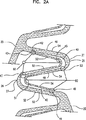
図2Aは、更なる例証のために僅かに拡大させられている点を除き、図2と同一である
。この図2Aにおいて、主要ヒンジ点60は、蛇状帯18においてスリット40に沿って示されている。図示される実施形態において、6個の主要ヒンジ点(PHP)がある。図2Aから分かるように、第1PHP43は、ストラット46のセグメント52の端部において、スリット40の第1端42に配置される。第2PHP45は、ストラット46のセグメント52及びストラット48のセグメント52の間の谷28に配置される。第3PHP47は、頂26に隣接するストラット48のセグメント52の端部において、ストラット48のセグメント52とストラット50のセグメント52の間に配置される。PHP47は、ストラット48のセグメント52の側において、頂26の頂点27からオフセットされている。第4PHP49は、ストラット50のセグメント54の端部において、スリット40の第2端44に配置される。第5PHP51は、ストラット48のセグメント54及びストラット50のセグメント54の間の谷28に配置される。また第6PHP53は、ストラット48のセグメント54及びストラット46のセグメント54の間において、頂26に隣接するストラット48のセグメント54の端部に配置される。PHP53は、ストラット48のセグメント54の側において、谷26の頂点27からオフセットされている。ステント10の拡張に際して、スリット40/ICC36と関連付けられたストラット(46,48,50)のセグメント(52,54)は、主要ヒンジ点60の周りを回転する。
FIG. 2A is identical to FIG. 2 except that it is slightly enlarged for further illustration. In this FIG. 2A, the
PHPは細くされた個所であり、そこでは、拡張の際に、塑性変形が生じる。ヒンジ点の位置及びデザインはまた、PHPを規定するために容易に目立たない応力集中部を引き起こすべく、有限要素解析法を使用して構想されてよい。ヒンジ点は、多角形ICC構造体の頂点に、又はその付近に配置される。ICC構造体が拡大させられた時に、ICC構造体の頂点はヒンジ式に動くと共に、多角形形状を拡大させるように変形する。 PHP is a thinned portion where plastic deformation occurs during expansion. The location and design of the hinge point may also be envisioned using finite element analysis methods to cause stress concentrations that are not easily noticeable to define the PHP. The hinge point is located at or near the vertex of the polygonal ICC structure. When the ICC structure is enlarged, the vertex of the ICC structure moves in a hinged manner and deforms to enlarge the polygonal shape.
図3に示されるように、ステント10の半径方向への拡張に際して、ICC36は、スリット40から最大限ICC36まで、面積が増加する。図3の矢印は、ICC36を画定するストラット46,48,50のセグメント52,54の移動方向を示す。蛇状帯18の円周方向への伸長は、ストラット46,48,50のセグメント52,54を主要ヒンジ点60の周りで回転させる。
As shown in FIG. 3, the
拡張に際して、結果的に生じるICC36の形状は多角形である。特定の内角寸法及び配置は、展開に際して変化する。ICC36は、最終的に展開させられる直径に従って、必要に応じて開く。5ミリメートルに展開させられたステントは、4ミリメートルに展開させられた同じステントよりも大きい角度を有し得る。
Upon expansion, the resulting
幾つかの実施形態において、多角形ICC36は6個の側面を有すると共に、2個の内優角72、2個の内鋭角70、及び鋭角、鈍角、又は直角であり得る2個の内角71を有する。内角71は約90度(プラスマイナス15度)であり得る。ICC多角形の内側「角部」の幾つかは、頂26及び/又は谷28の内側部分と同じように丸くされているが、多角形の内側角部であると考えられる。
In some embodiments, the
図3に示されるように、ステント10の拡張に際して、ストラット46,48,50のセグメント52,54は、図2のように、ステント10が非拡張状態にある時には、蛇状帯18の位置に関して、蛇状帯18との整列方向80に移動する。図3に示すように、ステントが拡張させられると共に、ICC36が拡張させられた時には、ストラット46の第1セグメント52及びストラット50の第2セグメント54は、蛇状帯18と大きく整列させられる。これに関して、これらのセグメントは、蛇状帯の軸80に対して45度未満の角度81にあることが意味される。また、ICC36が完全に拡張させられた時に、ストラット46のセグメント52及びストラット48のセグメント52の交点83、並びにストラット48のセグメント54及びストラット50のセグメント54の交点85は、
蛇状帯18の軸80とほぼ整列させられる。
As shown in FIG. 3, upon expansion of the
It is substantially aligned with the
また、図3に示されるように、ストラット46のセグメント52は、ストラット50のセグメント54とほぼ平行であると共に、(ステントの長さに関して)遠位にある。ストラット46のセグメント54はストラット50のセグメント52とほぼ平行であり、またストラット48のセグメント52及び54は、互いにほぼ平行である。幾つかの実施形態において、これらの相対位置は、図2に示すICC36の非拡張状態から、図3に示すそれらの拡張状態へ、ほぼ維持される。
Also, as shown in FIG. 3, the
図面に示される実施形態において、セグメントの直線部に関して、ストラット46のセグメント52及びストラット50のセグメント54は、ほぼ同じ長さであると共に、両方とも、ストラット46,48,50の残りのセグメントよりも短い。ストラット48のセグメント52及び54は、ほぼ同じ長さであってよく、またストラット46のセグメント54及びストラット50のセグメント52は、ほぼ同じ長さであってよい。
In the embodiment shown in the drawings, with respect to the straight portion of the segment, the
本発明のステントの幾つかの実施形態において、図3に示すように、ストラット46のセグメント52及びストラット50のセグメント54は、対応して対をなすセグメントよりも小さい幅を有する。ストラット46及び50の両方のセグメント52及び54の幅は、その直線部に沿ってほぼ一定であってもよい。ストラット48のセグメント52及び54の幅は、それらの直線部長さに沿って、逆に変化する幅を有してよい。ストラット48のセグメント52は、ストラット46のセグメント52との連結部から、ストラット50のセグメント52との連結部まで幅が増加し、またセグメント54は、ストラット46のセグメント54との連結部から、ストラット50のセグメント54との連結部まで、反対に幅が減少する。本発明はまた、顕著にヒンジ60を細くすることなく、これらの様々な厚さデザインも企図する。パラメータは、ICC構造体の開放特性を最適化するように、また特定のステントデザイン及びステントに組み入れられるICC構造体の特性に応じて、構想されてよい。
In some embodiments of the stent of the present invention, as shown in FIG. 3, the
幾つかの実施形態において、図6に示すように、スリット40の第1端42が第1ストラット46に配置される代わりに、その第1端42は相互連結ストラット20に配置される。相互連結ストラット20は、相互連結ストラット20が第1ストラット46及び第2ストラット48から形成される頂26の頂点227に連結される隣接帯18の頂26の頂点127から測定される。相互連結ストラット20の長さは、頂点127及び頂点227の間の距離によって画定される。幾つかの実施形態において、第1端42は、頂点127から始まる相互連結ストラット20の最初の半分に配置される。幾つかの実施形態において、第1端42は、頂点127から始まる相互連結ストラット20の最初の三分の一に配置される。スリット40の終点44の位置決めについては、図4を参照して、上記に説明されている。
In some embodiments, instead of the
幾つかの実施形態において、図7に示すように、図4において図示及び測定されるスリット40は、相互連結ストラット20の第3端142まで延出する。この特定の実施形態において、相互連結ストラット20はストラットを相互に連結する谷即ちくぼみ128の頂226であるが、頂ストラットの頂であってもよい。スリット40は、図4に示すように、第3ストラット50で終端44をなしてよいが、幾つかの実施形態において、図7に示すように、スリット40は第4ストラット75まで延出してよい。この場合には、第2端44の位置は、図4に関して上述したように、第4ストラット75の第3ストラット50にあるのと同じ場所に位置決めされる。
In some embodiments, as shown in FIG. 7, the
図7に示す実施形態において、相互連結ストラット20は、相互連結ストラット20が第2ストラット48及び第3ストラット50から形成される頂26の実質上の頂点327
に連結される隣接帯118の谷128から測定される。当然のことながら、幾つかの実施形態において、相互連結ストラット20は第1ストラット46及び第2ストラット48から形成される頂26から延出し、また幾つかの実施形態において、相互連結ストラット20は、第3ストラット50及び第4ストラット75から形成される頂26から延出してよい。相互連結ストラット20の長さは、隣接する帯118の谷128から実質上の頂点327までの間の距離によって画定される。幾つかの実施形態において、第3端142は、谷128で始まる相互連結ストラット20の最初の半分に配置される。幾つかの実施形態において、第3端142は、谷128で始まる相互連結ストラット20の最初の三分の一に配置される。
In the embodiment shown in FIG. 7, the interconnecting
Measured from valleys 128 of
本発明はまた、本明細書に説明されるスリット40のデザインのいずれか、幾つか、又は全てを有するステントを企図する。
上述した実施形態において、本発明のステントは、ほぼ一定の直径を有する。直径が一定ではないステントを準備するために、上述したステントのパターンを変更することも、本発明の範囲内にある。例えば、拡張状態において先細になるステントは、ステントの一端から他端まで、或いはステントの所望部分に沿ってのみ、蛇状帯の幅を減少させることにより、作られてもよい。細長くされた部分は、ステントに沿ったいずれかに設けられてよい。例えば、ステントの一端から始まるステントの半分に、テーパが設けられてよい。細長く拡張させられるステントを得るための別の方法としては、蛇状帯及び/又は連結部の剛性が、ステントの全長に沿って変化するように、蛇状帯及び/又は連結部の剛性を変化させることである。蛇状帯及び/又は連結部の剛性は、長さ、幅、又は厚みを変えることにより、付加的な補強材料を加えることにより、ステント材料の物理的特性を変化させるために化学的又は機械的手段を使用することにより、或いは1個又は一連の弾性要素をステントの周りに適用することにより変更され得る。
The present invention also contemplates stents having any, some, or all of the
In the embodiments described above, the stent of the present invention has a substantially constant diameter. It is also within the scope of the present invention to modify the stent pattern described above to prepare a stent with a non-constant diameter. For example, a stent that tapers in the expanded state may be made by reducing the width of the serpentine band from one end of the stent to the other, or only along the desired portion of the stent. The elongated portion may be provided anywhere along the stent. For example, the half of the stent starting from one end of the stent may be tapered. Another way to obtain an elongate stent is to change the stiffness of the serpentine band and / or joint so that the stiffness of the serpentine band and / or joint varies along the entire length of the stent. It is to let you. The stiffness of the serpentine band and / or the joint can be changed chemically or mechanically to alter the physical properties of the stent material by changing the length, width, or thickness, or by adding additional reinforcing materials. It can be altered by using means or by applying one or a series of elastic elements around the stent.
本明細書に開示される本発明のステントパターンはまた、特性が全長又は一部に亘り変化するステントを提供するために、他の周知のステントデザインと合わせて使用されてもよい。本発明のスリットパターンはまた、螺旋状デザイン、トリボナーテデザイン等、蛇状でないステントデザインに使用されてもよい。 The inventive stent pattern disclosed herein may also be used in conjunction with other well-known stent designs to provide a stent whose properties change over its entire length or in part. The slit pattern of the present invention may also be used in non-snake shaped stent designs, such as spiral designs, tribonate designs, and the like.
本発明は更に、本明細書に開示されるデザインに係るステントの製造方法に向けられる。本発明は更に、本明細書に説明されるステントの送出及び拡張方法に向けられる。
本発明のステントは、1個又は複数の高分子、1個又は複数の金属、又は(複数の)高分子及び(複数の)金属の組み合わせを含む適当な生体適合材料から作られてよい。適当な材料の例には、生体適合性をも有する生分解性材料を含む。生分解性とすることにより、材料が、通常の生物学的方法の一部として、無害の複合物に破壊又は分解されることが意味される。適当な生分解性材料には、ポリ乳酸、ポリグリコール酸(PGA)、コラーゲン、又は他の結合たんぱく質又は天然材料、ポリカプロラクトン、玻尿酸、接着性たんぱく質、これらの材料の共重合体、並びにこれらの複合物及び化合物、及び他の生分解性高分子の組み合わせを含む。使用され得る他の高分子には、ポリエステル及びポリカーボネート共重合体を含む。適当な金属の例には、ステンレス鋼、チタン、タンタル、プラチナ、タングステン、金、上記金属のいずれかの合金を含むが、これらに限定されない。適当な合金の例には、プラチナイリジウム合金、エルジロイ及びフィノックスを含むコバルト‐クロム合金、MP35N合金、及びニッケル‐チタン合金、例えばニチノールを含む。
The present invention is further directed to a method of manufacturing a stent according to the design disclosed herein. The present invention is further directed to the stent delivery and expansion methods described herein.
The stent of the present invention may be made from a suitable biocompatible material comprising one or more polymers, one or more metals, or a combination of polymer (s) and metal (s). Examples of suitable materials include biodegradable materials that are also biocompatible. By being biodegradable, it is meant that the material is destroyed or degraded into harmless composites as part of normal biological methods. Suitable biodegradable materials include polylactic acid, polyglycolic acid (PGA), collagen, or other binding or natural materials, polycaprolactone, uric acid, adhesive proteins, copolymers of these materials, as well as these Includes combinations of composites and compounds, and other biodegradable polymers. Other polymers that can be used include polyester and polycarbonate copolymers. Examples of suitable metals include, but are not limited to, stainless steel, titanium, tantalum, platinum, tungsten, gold, and alloys of any of the above metals. Examples of suitable alloys include platinum iridium alloys, cobalt-chromium alloys including Elgiloy and Finox, MP35N alloys, and nickel-titanium alloys such as nitinol.
本発明のステントは、超弾性ニチノール又はばね鋼等の形状記憶材料から作られてよく、或いは弾性変形可能な材料から作られてよい。形状記憶材料の場合には、ステントには記憶された形状が備えられ、次に直径が小さくされた形状に変形させられ得る。ステントは、転移温度に加熱されると共に、抑制力がそこから取り除かれた際に、その記憶された
形状に復帰し得る。
The stent of the present invention may be made from a shape memory material such as superelastic nitinol or spring steel, or may be made from an elastically deformable material. In the case of a shape memory material, the stent can be provided with a memorized shape and then deformed into a reduced diameter shape. The stent can be heated to the transition temperature and return to its memorized shape when the restraining force is removed therefrom.
本発明は、一般的にオーバーザワイヤ(OTW)カテーテル及び迅速交換(RX)カテーテルと呼ばれ、ガイドワイヤと組み合わせて使用される2種類のカテーテルの両方に組み入れられ得る。オーバーザワイヤカテーテル及び迅速交換カテーテルの両方の構成及び使用法については、当該技術分野において周知である。 The present invention, commonly referred to as over-the-wire (OTW) catheters and rapid exchange (RX) catheters, can be incorporated into both types of catheters used in combination with guidewires. The construction and use of both over-the-wire catheters and rapid exchange catheters are well known in the art.
幾つかの実施形態において、ステント、送出システム、又はアセンブリの他の部分は、X線、MRI、超音波等の画像診断法によって検知可能な1個又は複数の領域、帯域、被膜、部材等を含んでよい。幾つかの実施形態において、ステント及び/又は隣接するアセンブリの少なくとも一部は、少なくとも部分的に放射線不透過性を有する。 In some embodiments, the stent, delivery system, or other part of the assembly includes one or more regions, bands, coatings, members, etc. that can be detected by diagnostic imaging methods such as X-ray, MRI, ultrasound, etc. May include. In some embodiments, at least a portion of the stent and / or adjacent assembly is at least partially radiopaque.
幾つかの実施形態において、ステントの少なくとも一部は、1個又は複数の治療薬送出機構を含むように構成される。しばしば治療薬は、ステントの表面領域に載置される材料コーティング又は他の(複数の)材料層の形態をなし得、ステントの埋設部位又はそれに隣接する領域で解放されるように適合させられる。 In some embodiments, at least a portion of the stent is configured to include one or more therapeutic agent delivery mechanisms. Often the therapeutic agent can be in the form of a material coating or other material layer (s) placed on the surface area of the stent and is adapted to be released at or near the site of implantation of the stent.
治療薬は、非遺伝子剤、遺伝子剤、細胞物質等の医薬品又は他の薬製品であってよい。適当な非遺伝子治療薬の幾つかの例には:ヘパリン、ヘパリン誘導体、血管細胞成長促進物、成長因子阻害薬、パクリタキセル等の非血栓形成薬を含むが、これらに限定されない。薬が遺伝子治療薬を含む場合には、このような遺伝子剤は、:DNA、RNA、及びこれら夫々の誘導体、及び/又は成分、ヘッジホッグたんぱく質等を含み得るが、これらに限定されない。治療薬が細胞物質を含む場合には、細胞物質は:ヒト起源及び/又は非ヒト起源の細胞、並びにそれら夫々の成分及び/又はその誘導体を含み得るが、これらに限定されない。治療薬が高分子剤を含む場合には、高分子剤はポリスチレン‐ポリイソブチレン‐ポリスチレントリブロック共重合体(SIBS)、ポリ酸化エチレン、シリコンゴム、及び/又は他の適当な基質であり得る。 The therapeutic agent may be a non-genetic agent, a genetic agent, a pharmaceutical agent such as cellular material, or other pharmaceutical product. Some examples of suitable non-gene therapeutic agents include, but are not limited to: non-thrombogenic agents such as: heparin, heparin derivatives, vascular cell growth promoters, growth factor inhibitors, paclitaxel and the like. Where the drug includes a gene therapy drug, such gene agents may include, but are not limited to: DNA, RNA, and their respective derivatives and / or components, hedgehog proteins, and the like. Where the therapeutic agent includes cellular material, the cellular material can include, but is not limited to: cells of human and / or non-human origin, and their respective components and / or derivatives thereof. Where the therapeutic agent includes a polymeric agent, the polymeric agent can be a polystyrene-polyisobutylene-polystyrene triblock copolymer (SIBS), a polyethylene oxide, silicone rubber, and / or other suitable substrate.
本発明のステントは更に、治療用コーティングに加えて、或いはそれに代えて、高分子コーティングを含み得る。適当な高分子コーティング材料は、ポリカルボン酸、酢酸セルローセ及びセルロースニトレートを含むセルロース系高分子、ゼラチン、ポリビニルピロリドン、架橋性ポリビニルピロリドン、無水マレイン酸高分子を含むポリアンヒドリド、ポリアミド、ポリビニルアルコール、EVA等のビニル単量体の共重合体、ポリビニルエーテル、ポリビニル芳香族、酸化ポリエチレン、グリコサミノグリカン、多糖類、ポリエチレンテレフタレートを含むポリエステル、ポリアクリルアミド、ポリエーテル、ポリエーテルサルホン、ポリカーボネート、ポリプロピレンを含むポリアルキレン、ポリエチレン、及び高分子量ポリエチレン、ポリテトラフルオロエチレンを含むハロゲン化ポリアルキレン、ポリウレタン、ポリオルトエステル、たんぱく質、ポリペプチド、シリコン、シロキサン重合体、ポリ乳酸、ポリグリコール酸、ポリカプロラクトン、ポリヒドロキシブチレート、及びそれらの配合物並びに共重合体、ポリウレタンディスパージョン等の高分子ディスパージョンからのコーティング、例えばBAYHDROL.RTM、フィブリン、コラーゲン、及びその誘導体、セルロース等の多糖類、澱粉、デキストラン、アルギン酸及び誘導体、ヒアルロン酸、スクワランエマルジョンを含む。ポリアクリル酸が特に好ましく、ポリアクリル酸は、HYDROPLUS.RTM(マサチューセッツ州ナティック(Natick)にあるボストンサイエンティフィックコーポレーション(Boston Scientific Corporation))として市販されており、また米国特許第5,091,205号に記載されており、その開示はこの結果、参照することにより、本明細書に組み入れられる。本発明の特に好ましい実施形態において、高分子は、ポリ乳酸及びポリカプロラクトンの共重合体である。 The stent of the present invention may further comprise a polymeric coating in addition to or instead of the therapeutic coating. Suitable polymeric coating materials include cellulosic polymers including polycarboxylic acids, cellulose acetate and cellulose nitrate, gelatin, polyvinyl pyrrolidone, crosslinkable polyvinyl pyrrolidone, polyanhydrides including maleic anhydride polymers, polyamides, polyvinyl alcohol, Copolymer of vinyl monomers such as EVA, polyvinyl ether, polyvinyl aromatic, polyethylene oxide, glycosaminoglycan, polysaccharides, polyester including polyethylene terephthalate, polyacrylamide, polyether, polyethersulfone, polycarbonate, polypropylene Including polyalkylenes, polyethylene, and high molecular weight polyethylene, halogenated polyalkylenes including polytetrafluoroethylene, polyurethanes, polyorthoesters, proteins Coatings from polymeric dispersions such as polypeptides, silicones, siloxane polymers, polylactic acid, polyglycolic acid, polycaprolactone, polyhydroxybutyrate, and their blends and copolymers, polyurethane dispersions, eg BAYHDROL . RTM, fibrin, collagen, and derivatives thereof, polysaccharides such as cellulose, starch, dextran, alginic acid and derivatives, hyaluronic acid, squalane emulsion. Polyacrylic acid is particularly preferred, and polyacrylic acid is HYDROPLUS. RTM (Boston Scientific Corporation, Natick, Massachusetts) is commercially available and is described in US Pat. No. 5,091,205, the disclosure of which is hereby incorporated by reference Is incorporated herein by reference. In a particularly preferred embodiment of the present invention, the polymer is a copolymer of polylactic acid and polycaprolactone.
使用に際して、本明細書に開示されるステントは一般的に、カテーテルを介して、所望の生体位置へ送出される。カテーテルの選択は、使用されるステントの種類、及びステントが送出される位置に左右される。 In use, the stents disclosed herein are generally delivered via a catheter to the desired living location. The choice of catheter depends on the type of stent used and the location where the stent is delivered.
本発明のステントを製造するために、適当な方法が使用されてよい。例えば、上記に記載される方法に加えて、本発明のステントは、ステントの個々の部分を準備すると共に、それらを溶接、接着剤の使用、又は他の適当な接合技術によって互いに連結させることにより製造されてもよい。この製造技術の一覧は、網羅的であることを意味するものではない。本発明のステントを製造するために、他の製造技術が用いられてもよい。 Any suitable method may be used to manufacture the stent of the present invention. For example, in addition to the methods described above, the stents of the present invention can be prepared by preparing individual portions of the stent and joining them together by welding, the use of adhesives, or other suitable joining techniques. May be manufactured. This list of manufacturing techniques is not meant to be exhaustive. Other manufacturing techniques may be used to manufacture the stent of the present invention.
上記の開示は、例証的なものであって、網羅的なものではない。本説明は、当該技術分野に属する通常の知識を有する者に対して、多くの変形物及び代替物を示唆する。これらの代替物及び変形物全ては、「を含む」という用語が「を含むが限定されない」を意味する場合に、請求項の範囲内に含まれると意図される。当該技術分野を熟知する者であれば、本明細書に説明される特定の実施形態の他の同等物を認識し得、このような同等物はまた、請求項によって含まれると意図される。 The above disclosure is illustrative and not exhaustive. This description suggests many variations and alternatives to those of ordinary skill in the art. All these alternatives and variations are intended to be included within the scope of the claims where the term "including" means "including but not limited to". Those skilled in the art may recognize other equivalents to the specific embodiments described herein, and such equivalents are also intended to be encompassed by the claims.
従属請求項に表される特定の特徴は、本発明が、従属請求項の特徴の他の可能な組み合わせを有する他の実施形態にも特に向けられると認識されるように、本発明の範囲内にある他の方法で、互いに組み合わされ得る。例えば、請求項の公表のために、後続の従属請求項は、全ての先の請求項からの複数従属形式で代替的に記載されると見なされてよく、先の請求項は、この複数従属形式が法域内で受け入れられる形式であるならば、このような従属請求項において言及される全ての先行物を有する(例えば、請求項1に直接従属する各請求項は、全ての先の請求項に従属すると代替的に見なされる)。複数従属請求項形式が制限される法域では、後続の従属請求項は各々、以下の従属請求項に記載される特定の請求項以外の前の先行物保有請求項への従属性をもたらす単独従属請求項形式で代替的に記載されると見なされる(例えば、請求項4は、請求項2又は請求項3に代替的に従属すると考慮され;請求項5は請求項1〜請求項3のいずれかに代替的に従属すると考慮される)。
The particular features expressed in the dependent claims are within the scope of the invention, as it will be appreciated that the invention is particularly directed to other embodiments having other possible combinations of the features of the dependent claims. Can be combined with each other in other ways. For example, for the purpose of publishing a claim, subsequent dependent claims may be considered to be alternatively described in a multiple dependent form from all previous claims, and the previous claim If the form is one that is acceptable within the jurisdiction, it has all the predecessors mentioned in such dependent claims (for example, each claim directly dependent on claim 1 shall claim all previous claims) Subordinate to). In jurisdictions where multiple dependent claim forms are restricted, each subsequent dependent claim is a single dependent that results in a dependency on the preceding predecessor claim other than the specific claim listed in the following dependent claim It is considered to be described alternatively in claim form (for example, claim 4 is considered to be subordinate to claim 2 or claim 3;
これで、本発明の好適且つ代替の実施形態の説明を終える。当該技術分野に属する者であれば、本明細書に記載される特定の実施形態の他の同等物を認識し得、この同等物は、本明細書に添付される請求項によって包括されると意図される。 This completes the description of the preferred and alternative embodiments of the invention. Those skilled in the art will recognize other equivalents to the specific embodiments described herein, which equivalents are encompassed by the claims appended hereto. Intended.
Claims (29)
軸方向に間隔があけられた複数の蛇状帯と、各蛇状帯は複数のストラットを含み、隣接するストラットは互いに連結されて、複数の頂及び谷を形成するものであり、
前記蛇状帯を軸方向に連結する複数の相互連結ストラットと、
軸方向に隣接する蛇状帯及び円周方向に隣接する相互連結ストラットによって画定される複数のセルとを含み、
前記ステントが前記非拡張状態にある時には、各帯は複数のスリットを含み、各スリットは、非直線状であると共に第1端から第2端まで連続しており、また3個の連続連結されたストラット各々の少なくとも一部に形成され、
前記3個の連続連結ストラットは、第1ストラットと、第2ストラットと、第3ストラットとを含み、該第1、第2、及び第3ストラット各々は、第1端及び第2端を有し、該第1ストラットの第2端は該第2ストラットの第1端と連結されると共に、該第2ストラットの第2端は該第3ストラットの第1端と連結されており、前記スリットの第1端は該第1ストラットに位置決めされると共に、前記スリットの第2端は該第3ストラットに位置決めされ、
前記ステントの拡張状態への拡張に際して、該スリット各々は、コラム内セル、即ちICCを形成するように、寸法が拡張する
ことを特徴とするステント。A stent having a distal end, a distal end, and a longitudinal axis extending from the distal end to the distal end, the stent having an unexpanded state and an expanded state, the stent further comprising:
A plurality of serpentine bands spaced in the axial direction, each serpentine band including a plurality of struts, adjacent struts are connected together to form a plurality of peaks and valleys,
A plurality of interconnecting struts connecting the serpentine bands in the axial direction;
A plurality of cells defined by axially adjacent serpentine bands and circumferentially adjacent interconnecting struts;
When the stent is in the unexpanded state, each band includes a plurality of slits, each slit being non-linear and continuous from the first end to the second end, and three consecutively connected. Formed on at least a portion of each strut,
The three consecutively connected struts include a first strut, a second strut, and a third strut, each of the first, second, and third struts having a first end and a second end. The second end of the first strut is connected to the first end of the second strut, and the second end of the second strut is connected to the first end of the third strut, A first end is positioned on the first strut, and a second end of the slit is positioned on the third strut;
Upon expansion of the stent to an expanded state, each of the slits expands in size so as to form an in-column cell, or ICC.
軸方向に間隔があけられた複数の帯と、各帯は複数のストラットを含み、隣接するストラットは互いに連結されて、複数の頂及び谷を形成し、
前記帯を軸方向に連結する複数の相互連結ストラットと、
軸方向に隣接する帯及び円周方向に隣接する相互連結ストラットによって画定される複数のセルとを含み、
前記ステントが前記非拡張状態にある時に、各帯は複数のスリットを含み、各スリットは非直線状であると共に、第1端から第2端まで連続しており、該第1端は前記相互連結ストラットの1個内に配置され、また各スリットは、各帯の2個の連続連結ストラット各々の少なくとも一部に形成され、
前記軸方向に間隔があけられた複数の帯は蛇状帯であり、また前記ステントの拡張状態への拡張に際して、前記スリット各々は、コラム内セル、即ちICCを形成するように、寸法が拡張することを特徴とするステント。A stent having a distal end, a distal end, and a longitudinal axis extending from the distal end to the distal end, wherein the stent has an unexpanded state and an expanded state;
A plurality of axially spaced bands, each band including a plurality of struts, adjacent struts connected together to form a plurality of peaks and valleys;
A plurality of interconnecting struts connecting the strips in the axial direction;
A plurality of cells defined by axially adjacent bands and circumferentially adjacent interconnect struts;
When the stent is in the non-expanded state, each band includes a plurality of slits, each slit is non-linear and is continuous from a first end to a second end, the first ends being the mutual ends. Located in one of the connecting struts, and each slit is formed in at least a portion of each of the two consecutive connecting struts of each band ;
The plurality of axially spaced bands are serpentine bands, and each of the slits expands in size to form an in-column cell, or ICC, when the stent is expanded to an expanded state. A stent characterized by that.
軸方向に間隔があけられた複数の帯と、各帯は複数のストラットを含み、隣接するストラットは、互いに連結されて、複数の頂及び谷を形成し、
前記帯を軸方向に連結する複数の相互連結ストラットと、
軸方向に隣接する帯及び円周方向に隣接する相互連結ストラットによって画定される複数のセルとを含み、
前記ステントが前記非拡張状態にある時に、各帯は複数のスリットを含み、各スリットは非直線状であると共に、第1端から第2端へ連続しており、且つ3個の連続して連結されたストラット各々の少なくとも一部に形成され、また各スリットは、隣接する相互連結ストラットまで延出し、
前記軸方向に間隔があけられた複数の帯は蛇状帯であり、また前記ステントの前記拡張状態への拡張に際して、前記スリット各々は、コラム内セル、即ちICCを形成するように、寸法が拡張することを特徴とするステント。A stent having a distal end, a distal end, and a longitudinal axis extending from the distal end to the distal end, wherein the stent has an unexpanded state and an expanded state;
A plurality of axially spaced bands, each band including a plurality of struts, adjacent struts connected together to form a plurality of peaks and valleys;
A plurality of interconnecting struts connecting the strips in the axial direction;
A plurality of cells defined by axially adjacent bands and circumferentially adjacent interconnect struts;
When the stent is in the non-expanded state, each band includes a plurality of slits, each slit is non-linear and is continuous from the first end to the second end, and three consecutive formed on at least a portion of the connecting struts each, and each slit, and extends to interconnecting struts adjacent,
The plurality of axially spaced bands are serpentine bands, and when the stent is expanded to the expanded state, each of the slits is dimensioned to form an in-column cell, or ICC. A stent characterized by expansion .
Applications Claiming Priority (5)
| Application Number | Priority Date | Filing Date | Title |
|---|---|---|---|
| US84387306P | 2006-09-12 | 2006-09-12 | |
| US60/843,873 | 2006-09-12 | ||
| US11/844,583 | 2007-08-24 | ||
| US11/844,583 US20080065196A1 (en) | 2006-09-12 | 2007-08-24 | Intra-Columnar Cell Features to Improve Drug Distribution and Scaffolding of a Stent |
| PCT/US2007/019363 WO2008033245A1 (en) | 2006-09-12 | 2007-09-05 | Intra-columnar cell features to improve drug distribution and scaffolding of a stent |
Publications (3)
| Publication Number | Publication Date |
|---|---|
| JP2010503427A JP2010503427A (en) | 2010-02-04 |
| JP2010503427A5 JP2010503427A5 (en) | 2011-05-19 |
| JP5185273B2 true JP5185273B2 (en) | 2013-04-17 |
Family
ID=38920707
Family Applications (1)
| Application Number | Title | Priority Date | Filing Date |
|---|---|---|---|
| JP2009527393A Expired - Fee Related JP5185273B2 (en) | 2006-09-12 | 2007-09-05 | In-column cell featuring improved drug distribution and stent support |
Country Status (5)
| Country | Link |
|---|---|
| US (1) | US20080065196A1 (en) |
| EP (1) | EP2068762B1 (en) |
| JP (1) | JP5185273B2 (en) |
| CA (1) | CA2661341A1 (en) |
| WO (1) | WO2008033245A1 (en) |
Families Citing this family (11)
| Publication number | Priority date | Publication date | Assignee | Title |
|---|---|---|---|---|
| US20090240318A1 (en) * | 2008-03-19 | 2009-09-24 | Boston Scientific Scimed, Inc. | Stent expansion column, strut and connector slit design |
| US20100049307A1 (en) * | 2008-08-25 | 2010-02-25 | Aga Medical Corporation | Stent graft having extended landing area and method for using the same |
| US20100082096A1 (en) * | 2008-09-30 | 2010-04-01 | Boston Scientific Scimed, Inc. | Tailored Luminal & Abluminal Drug Elution |
| DE102009010825B4 (en) * | 2009-02-26 | 2011-03-31 | Acandis Gmbh & Co. Kg | Medical implant with a lattice structure, method for its production and method for introducing the medical implant into a delivery system |
| US20100292777A1 (en) * | 2009-05-13 | 2010-11-18 | Boston Scientific Scimed, Inc. | Stent |
| US20110137407A1 (en) * | 2009-07-09 | 2011-06-09 | Thai Minh Nguyen | Bare metal stent with drug eluting reservoirs |
| US8114149B2 (en) * | 2009-10-20 | 2012-02-14 | Svelte Medical Systems, Inc. | Hybrid stent with helical connectors |
| CN102525701B (en) * | 2010-12-21 | 2015-06-17 | 先健科技(深圳)有限公司 | Absorbable blood vessel stent |
| US9381103B2 (en) * | 2014-10-06 | 2016-07-05 | Abbott Cardiovascular Systems Inc. | Stent with elongating struts |
| JP2018502687A (en) | 2015-03-12 | 2018-02-01 | ユタ−イナ ディーディーエス アンド アドバンスト セラピューティクス リサーチ センター | Stent with functional material coated in cell space |
| DE102016117398B4 (en) | 2016-09-15 | 2023-07-13 | Universität Rostock | Expandable structure |
Family Cites Families (13)
| Publication number | Priority date | Publication date | Assignee | Title |
|---|---|---|---|---|
| US3120336A (en) * | 1960-03-09 | 1964-02-04 | Du Pont | Pouch |
| US5091205A (en) | 1989-01-17 | 1992-02-25 | Union Carbide Chemicals & Plastics Technology Corporation | Hydrophilic lubricious coatings |
| US5843120A (en) * | 1994-03-17 | 1998-12-01 | Medinol Ltd. | Flexible-expandable stent |
| ATE395014T1 (en) | 1995-03-01 | 2008-05-15 | Boston Scient Scimed Inc | LONGITUDONLY FLEXIBLE AND EXPANDABLE STENT |
| DE19614160A1 (en) * | 1996-04-10 | 1997-10-16 | Variomed Ag | Stent for transluminal implantation in hollow organs |
| DE19717475C1 (en) * | 1997-04-25 | 1998-09-03 | Heraeus Gmbh W C | Radially expandable support structure or stent for tubular vessel in body |
| US6132461A (en) * | 1998-03-27 | 2000-10-17 | Intratherapeutics, Inc. | Stent with dual support structure |
| AU1084101A (en) * | 1999-10-14 | 2001-04-23 | United Stenting, Inc. | Stents with multilayered struts |
| US6440162B1 (en) * | 2000-07-26 | 2002-08-27 | Advanced Cardiovascular Systems, Inc. | Stent having increased scaffolding expandable bar arms |
| DE60124285T3 (en) * | 2000-09-29 | 2011-03-17 | Cordis Corp., Miami Lakes | COATED MEDICAL EQUIPMENT |
| US7014654B2 (en) * | 2001-11-30 | 2006-03-21 | Scimed Life Systems, Inc. | Stent designed for the delivery of therapeutic substance or other agents |
| US7090694B1 (en) * | 2003-11-19 | 2006-08-15 | Advanced Cardiovascular Systems, Inc. | Portal design for stent for treating bifurcated vessels |
| JP4797473B2 (en) * | 2005-07-11 | 2011-10-19 | ニプロ株式会社 | Flexible stent with excellent expandability |
-
2007
- 2007-08-24 US US11/844,583 patent/US20080065196A1/en not_active Abandoned
- 2007-09-05 EP EP07837742A patent/EP2068762B1/en not_active Not-in-force
- 2007-09-05 CA CA002661341A patent/CA2661341A1/en not_active Abandoned
- 2007-09-05 WO PCT/US2007/019363 patent/WO2008033245A1/en active Application Filing
- 2007-09-05 JP JP2009527393A patent/JP5185273B2/en not_active Expired - Fee Related
Also Published As
| Publication number | Publication date |
|---|---|
| US20080065196A1 (en) | 2008-03-13 |
| WO2008033245A1 (en) | 2008-03-20 |
| CA2661341A1 (en) | 2008-03-20 |
| EP2068762A1 (en) | 2009-06-17 |
| JP2010503427A (en) | 2010-02-04 |
| EP2068762B1 (en) | 2012-06-27 |
Similar Documents
| Publication | Publication Date | Title |
|---|---|---|
| JP5185273B2 (en) | In-column cell featuring improved drug distribution and stent support | |
| JP7102308B2 (en) | Stent | |
| EP2059199B1 (en) | Longitudinally flexible expandable stent | |
| US7540881B2 (en) | Bifurcation stent pattern | |
| US8512392B2 (en) | Stent design with struts of various angles and stiffness | |
| US7988720B2 (en) | Longitudinally flexible expandable stent | |
| JP2009513300A (en) | Stent configuration | |
| US20070225798A1 (en) | Side branch stent | |
| JP2008541841A (en) | Initiation geometry of stent side branch | |
| JP2014508559A (en) | Multi-stage open stent design | |
| JP2009528886A (en) | Bifurcated stent with uniform side branch protrusion | |
| EP1993488A1 (en) | Bifurcated stent with surface area gradient | |
| US20100010618A1 (en) | Overlapping Stent |
Legal Events
| Date | Code | Title | Description |
|---|---|---|---|
| A521 | Written amendment |
Free format text: JAPANESE INTERMEDIATE CODE: A523 Effective date: 20091127 |
|
| A621 | Written request for application examination |
Free format text: JAPANESE INTERMEDIATE CODE: A621 Effective date: 20100903 |
|
| A521 | Written amendment |
Free format text: JAPANESE INTERMEDIATE CODE: A523 Effective date: 20110330 |
|
| A977 | Report on retrieval |
Free format text: JAPANESE INTERMEDIATE CODE: A971007 Effective date: 20120216 |
|
| A131 | Notification of reasons for refusal |
Free format text: JAPANESE INTERMEDIATE CODE: A131 Effective date: 20120221 |
|
| RD04 | Notification of resignation of power of attorney |
Free format text: JAPANESE INTERMEDIATE CODE: A7424 Effective date: 20120301 |
|
| A521 | Written amendment |
Free format text: JAPANESE INTERMEDIATE CODE: A523 Effective date: 20120517 |
|
| TRDD | Decision of grant or rejection written | ||
| A01 | Written decision to grant a patent or to grant a registration (utility model) |
Free format text: JAPANESE INTERMEDIATE CODE: A01 Effective date: 20121225 |
|
| A61 | First payment of annual fees (during grant procedure) |
Free format text: JAPANESE INTERMEDIATE CODE: A61 Effective date: 20130117 |
|
| R150 | Certificate of patent or registration of utility model |
Free format text: JAPANESE INTERMEDIATE CODE: R150 |
|
| FPAY | Renewal fee payment (event date is renewal date of database) |
Free format text: PAYMENT UNTIL: 20160125 Year of fee payment: 3 |
|
| LAPS | Cancellation because of no payment of annual fees |