EP2068762B1 - Intra-columnar cell features to improve drug distribution and scaffolding of a stent - Google Patents
Intra-columnar cell features to improve drug distribution and scaffolding of a stent Download PDFInfo
- Publication number
- EP2068762B1 EP2068762B1 EP07837742A EP07837742A EP2068762B1 EP 2068762 B1 EP2068762 B1 EP 2068762B1 EP 07837742 A EP07837742 A EP 07837742A EP 07837742 A EP07837742 A EP 07837742A EP 2068762 B1 EP2068762 B1 EP 2068762B1
- Authority
- EP
- European Patent Office
- Prior art keywords
- strut
- stent
- segment
- struts
- serpentine
- Prior art date
- Legal status (The legal status is an assumption and is not a legal conclusion. Google has not performed a legal analysis and makes no representation as to the accuracy of the status listed.)
- Not-in-force
Links
Images


Classifications
-
- A—HUMAN NECESSITIES
- A61—MEDICAL OR VETERINARY SCIENCE; HYGIENE
- A61F—FILTERS IMPLANTABLE INTO BLOOD VESSELS; PROSTHESES; DEVICES PROVIDING PATENCY TO, OR PREVENTING COLLAPSING OF, TUBULAR STRUCTURES OF THE BODY, e.g. STENTS; ORTHOPAEDIC, NURSING OR CONTRACEPTIVE DEVICES; FOMENTATION; TREATMENT OR PROTECTION OF EYES OR EARS; BANDAGES, DRESSINGS OR ABSORBENT PADS; FIRST-AID KITS
- A61F2/00—Filters implantable into blood vessels; Prostheses, i.e. artificial substitutes or replacements for parts of the body; Appliances for connecting them with the body; Devices providing patency to, or preventing collapsing of, tubular structures of the body, e.g. stents
- A61F2/82—Devices providing patency to, or preventing collapsing of, tubular structures of the body, e.g. stents
- A61F2/86—Stents in a form characterised by the wire-like elements; Stents in the form characterised by a net-like or mesh-like structure
- A61F2/90—Stents in a form characterised by the wire-like elements; Stents in the form characterised by a net-like or mesh-like structure characterised by a net-like or mesh-like structure
- A61F2/91—Stents in a form characterised by the wire-like elements; Stents in the form characterised by a net-like or mesh-like structure characterised by a net-like or mesh-like structure made from perforated sheet material or tubes, e.g. perforated by laser cuts or etched holes
- A61F2/915—Stents in a form characterised by the wire-like elements; Stents in the form characterised by a net-like or mesh-like structure characterised by a net-like or mesh-like structure made from perforated sheet material or tubes, e.g. perforated by laser cuts or etched holes with bands having a meander structure, adjacent bands being connected to each other
- A61F2002/9155—Adjacent bands being connected to each other
- A61F2002/91558—Adjacent bands being connected to each other connected peak to peak
-
- A—HUMAN NECESSITIES
- A61—MEDICAL OR VETERINARY SCIENCE; HYGIENE
- A61F—FILTERS IMPLANTABLE INTO BLOOD VESSELS; PROSTHESES; DEVICES PROVIDING PATENCY TO, OR PREVENTING COLLAPSING OF, TUBULAR STRUCTURES OF THE BODY, e.g. STENTS; ORTHOPAEDIC, NURSING OR CONTRACEPTIVE DEVICES; FOMENTATION; TREATMENT OR PROTECTION OF EYES OR EARS; BANDAGES, DRESSINGS OR ABSORBENT PADS; FIRST-AID KITS
- A61F2/00—Filters implantable into blood vessels; Prostheses, i.e. artificial substitutes or replacements for parts of the body; Appliances for connecting them with the body; Devices providing patency to, or preventing collapsing of, tubular structures of the body, e.g. stents
- A61F2/82—Devices providing patency to, or preventing collapsing of, tubular structures of the body, e.g. stents
- A61F2/86—Stents in a form characterised by the wire-like elements; Stents in the form characterised by a net-like or mesh-like structure
- A61F2/90—Stents in a form characterised by the wire-like elements; Stents in the form characterised by a net-like or mesh-like structure characterised by a net-like or mesh-like structure
- A61F2/91—Stents in a form characterised by the wire-like elements; Stents in the form characterised by a net-like or mesh-like structure characterised by a net-like or mesh-like structure made from perforated sheet material or tubes, e.g. perforated by laser cuts or etched holes
- A61F2/915—Stents in a form characterised by the wire-like elements; Stents in the form characterised by a net-like or mesh-like structure characterised by a net-like or mesh-like structure made from perforated sheet material or tubes, e.g. perforated by laser cuts or etched holes with bands having a meander structure, adjacent bands being connected to each other
- A61F2002/9155—Adjacent bands being connected to each other
- A61F2002/91575—Adjacent bands being connected to each other connected peak to trough
-
- A—HUMAN NECESSITIES
- A61—MEDICAL OR VETERINARY SCIENCE; HYGIENE
- A61F—FILTERS IMPLANTABLE INTO BLOOD VESSELS; PROSTHESES; DEVICES PROVIDING PATENCY TO, OR PREVENTING COLLAPSING OF, TUBULAR STRUCTURES OF THE BODY, e.g. STENTS; ORTHOPAEDIC, NURSING OR CONTRACEPTIVE DEVICES; FOMENTATION; TREATMENT OR PROTECTION OF EYES OR EARS; BANDAGES, DRESSINGS OR ABSORBENT PADS; FIRST-AID KITS
- A61F2220/00—Fixations or connections for prostheses classified in groups A61F2/00 - A61F2/26 or A61F2/82 or A61F9/00 or A61F11/00 or subgroups thereof
- A61F2220/0025—Connections or couplings between prosthetic parts, e.g. between modular parts; Connecting elements
- A61F2220/005—Connections or couplings between prosthetic parts, e.g. between modular parts; Connecting elements using adhesives
-
- A—HUMAN NECESSITIES
- A61—MEDICAL OR VETERINARY SCIENCE; HYGIENE
- A61F—FILTERS IMPLANTABLE INTO BLOOD VESSELS; PROSTHESES; DEVICES PROVIDING PATENCY TO, OR PREVENTING COLLAPSING OF, TUBULAR STRUCTURES OF THE BODY, e.g. STENTS; ORTHOPAEDIC, NURSING OR CONTRACEPTIVE DEVICES; FOMENTATION; TREATMENT OR PROTECTION OF EYES OR EARS; BANDAGES, DRESSINGS OR ABSORBENT PADS; FIRST-AID KITS
- A61F2220/00—Fixations or connections for prostheses classified in groups A61F2/00 - A61F2/26 or A61F2/82 or A61F9/00 or A61F11/00 or subgroups thereof
- A61F2220/0025—Connections or couplings between prosthetic parts, e.g. between modular parts; Connecting elements
- A61F2220/0058—Connections or couplings between prosthetic parts, e.g. between modular parts; Connecting elements soldered or brazed or welded
-
- A—HUMAN NECESSITIES
- A61—MEDICAL OR VETERINARY SCIENCE; HYGIENE
- A61F—FILTERS IMPLANTABLE INTO BLOOD VESSELS; PROSTHESES; DEVICES PROVIDING PATENCY TO, OR PREVENTING COLLAPSING OF, TUBULAR STRUCTURES OF THE BODY, e.g. STENTS; ORTHOPAEDIC, NURSING OR CONTRACEPTIVE DEVICES; FOMENTATION; TREATMENT OR PROTECTION OF EYES OR EARS; BANDAGES, DRESSINGS OR ABSORBENT PADS; FIRST-AID KITS
- A61F2230/00—Geometry of prostheses classified in groups A61F2/00 - A61F2/26 or A61F2/82 or A61F9/00 or A61F11/00 or subgroups thereof
- A61F2230/0002—Two-dimensional shapes, e.g. cross-sections
- A61F2230/0028—Shapes in the form of latin or greek characters
- A61F2230/0054—V-shaped
-
- A—HUMAN NECESSITIES
- A61—MEDICAL OR VETERINARY SCIENCE; HYGIENE
- A61F—FILTERS IMPLANTABLE INTO BLOOD VESSELS; PROSTHESES; DEVICES PROVIDING PATENCY TO, OR PREVENTING COLLAPSING OF, TUBULAR STRUCTURES OF THE BODY, e.g. STENTS; ORTHOPAEDIC, NURSING OR CONTRACEPTIVE DEVICES; FOMENTATION; TREATMENT OR PROTECTION OF EYES OR EARS; BANDAGES, DRESSINGS OR ABSORBENT PADS; FIRST-AID KITS
- A61F2250/00—Special features of prostheses classified in groups A61F2/00 - A61F2/26 or A61F2/82 or A61F9/00 or A61F11/00 or subgroups thereof
- A61F2250/0058—Additional features; Implant or prostheses properties not otherwise provided for
- A61F2250/0067—Means for introducing or releasing pharmaceutical products into the body
- A61F2250/0068—Means for introducing or releasing pharmaceutical products into the body the pharmaceutical product being in a reservoir
Landscapes
- Health & Medical Sciences (AREA)
- Engineering & Computer Science (AREA)
- Biomedical Technology (AREA)
- Heart & Thoracic Surgery (AREA)
- Life Sciences & Earth Sciences (AREA)
- Cardiology (AREA)
- Oral & Maxillofacial Surgery (AREA)
- Transplantation (AREA)
- Physics & Mathematics (AREA)
- Vascular Medicine (AREA)
- Optics & Photonics (AREA)
- Animal Behavior & Ethology (AREA)
- General Health & Medical Sciences (AREA)
- Public Health (AREA)
- Veterinary Medicine (AREA)
- Media Introduction/Drainage Providing Device (AREA)
- Prostheses (AREA)
Abstract
Description
- A stent is a medical device introduced to a body lumen and is well known in the art Typically, a stent is implanted in a blood vessel at the site of a stenosis or aneurysm endoluminally, i.e. by so-called "minimally invasive techniques" in which the stent in a radially reduced configuration, optionally restrained in a radially compressed configuration by a sheath and/or catheter, is delivered by a stent delivery system or "introducer" to the site where it is required. The introducer may enter me body from an access location outside the body, such as through the patient's skin, or by a "cut down" technique in which the entry blood vessel is exposed by minor surgical means.
- Stents, grafts, stent-grafts, vena cava filters, expandable frameworks, and similar implantable medical devices, collectively referred to hereinafter as stents, are radially expandable endoprostheses which are typically intravascular implants capable of being implanted transluminal and enlarged radially after being introduced percutaneously. Stents may be implanted in a variety of body lumens or vessels such as within the vascular system, urinary tracts, bile ducts, fallopian tubes, coronary vessels, secondary vessels, etc. They may be self-expanding, expanded by an internal radial force, such as when mounted on a balloon, or a combination of self-expanding and balloon expandable (hybrid expandable). An example of a balloon expandable stent is shown in
U.S. Pat No. 5843120 . An example of a self-expanding stent is described inWO 96/26689 - Stents may be created by methods including cutting or etching a design from a tubular stock, from a flat sheet which is cut or etched and which is subsequently rolled or from one or more interwoven wires or braids.
-
US 2003/0120336 A1 discloses a stent with a dual support structure. The known stent comprises beams having an undulating pattern to define a plurality of peaks and valleys forming cells. Slots are formed through the complete thickness of each of the beams. The slots extend between first and second ends, wherein first ends are adjacent to the longitudinal connection between two adjacent beams. The slots comprise a width which remains constant throughout its length. Upon expansion of the stent the cells assume a diamond-like shape while the width of the stent remains constant. -
US 7,090,694 B1 discloses a portal design for stent for treating bifurcated vessels. The bifurcating has an improved portal region between a proximal section and a distal section with the stent. The bifurcated stent can be expanded to a greater diameter than the remaining stent. In one example of the known bifurcated stent theportal region 28 is formed of nested peaks nested within adjacent peaks to form the portal region (cp.column 10, lines 10 - 19). -
US 6,440,162 B1 discloses an expandable stent with arms having expandable slits in the substantially straight arms.The problem of the invention is to provide stent patterns that provide proper scaffolding support and drug delivery in the expanded state, while also allowing for crimpability and for flexibility and deliverability in the unexpanded state. - The problem is solved by a stent according to
claim 1. - Without limiting the scope of the invention a brief summary of some of the claimed embodiments of the invention is set forth below. Additional details of the summarized embodiments of the invention and/or additional embodiments of the invention may be found in the Detailed Description of the Invention below.
- The present invention is directed toward a stent as disclosed in the appended claims having a plurality of axially spaced serpentine bands, each serpentine band having an axis circumferentially oriented around the longitudinal axis of the stent. The serpentine bands have a plurality of struts spaced along the axis of the serpentine band forming alternating peaks and troughs. The serpentine bands are interconnected via a plurality of interconnecting struts to form a plurality of cells defined by axially adjacent serpentine bands and circumferentially adjacent interconnecting struts. When the stent is in its unexpanded state, each serpentine band comprises a plurality of slits within the serpentine band, each slit being non-linear and continuous from a first end to a second end. Upon expansion of the stent to its expanded state, each of the slits expands in size to form an intra-columnar cell (ICC).
- According to the invention, each slit, from its first end to its second end, is formed in at least a portion of each of three consecutively connected struts.
- The slits are formed in three consecutively connected struts in a serpentine band. The three connected struts include a first strut, a second strut and third strut The first, second and third struts each have a first end and a second end. The second end of the first strut is connected to the first end of the second strut and the second end of the second strut is connected to the first end of the third strut. The first end of the slit is positioned in the first strut and the second end of the slit is positioned in the third strut.
- In some embodiments, the slit in the three consecutive struts crosses the axis of the serpentine band at least two times. In some embodiments, the slit crosses the axis of the serpentine band three times.
- In some embodiments, the slits are formed in three consecutively connected struts in a serpentine band. The three connected struts include a first strut, a second strut and third strut Each of the first, second and third struts have a first segment and a second segment, wherein the slit separates the first segment and second segment of the each of the first, second and third struts.
- In some embodiments, the first segment of the first strut is connected to the first segment of the second strut forming a trough, the first segment of the second strut is connected to the first segment of the third strut forming a peak, the second segment of the first strut is connected to the second segment of the second strut forming a peak and the second segment of the second strut is connected to the second segment of the third strut forming a trough.
- Upon expansion of the stent to its expanded state, each of the slits expands in size to form an intra-columnar cell (ICC). The ICC is substantially a polygon and has at least two inner reflex angles. In some embodiments, the ICC has at least two inner acute angles. In some embodiments, the ICC has at least four inner angles less than 180°.
- In some embodiments, the first and second segments of the first, second and third struts define the ICC and the first segment of the first strut is substantially parallel with the second segment of the third, strut. In some embodiments, the second segment of the first strut is substantially parallel with the first segment of the third strut. In some embodiments, the first segment of the second strut is substantially parallel with the second segment of the second strut.
- In some embodiments, the second segment of the first strut and the first segment of the third strut have greater widths than the first segment of the first strut and the second segment of the third strut. In some embodiments, the first segment and second segment of the second strut may vary in their width along their lengths.
- The serpentine bands may also comprise a plurality of primary hinge points, wherein, upon expansion of the stent and the forming of the ICC, the first and second segments of the first, second and third struts rotate around the primary hinge points, increasing the size of the slit to form the ICC. In some examples, a first primary hinge point is located in an end of the first segment of the second strut, wherein the first segment of the second strut and the first segment of the third strut pivot around the first primary hinge point A second primary hinge point may be located in an end of the second segment of the second strut, wherein the second segment of the second strut and the second segment of the first strut pivot around the second primary hinge point There also may be six primary hinge points.
- In some embodiments, the at least a portion of the stent is configured to include one or more mechanisms for the delivery of a therapeutic agent. Often the agent will be in the form of a coating or other layer (or layers) of material placed on a surface region of the stent and is adapted to be released at the site of the stent's implantation or areas adjacent thereto. The therapeutic and/or polymeric coatings may comprise one or more non-genetic therapeutic agents, genetic materials and cells and combinations thereof.
- In an example of the inventive stent is mounted on a stent delivery catheter. The present invention provides examples of methods of delivering the disclosed inventive stents to a target site in a bodily vessel.
- These and other embodiments that characterize the invention are pointed out with particularity in the claims annexed hereto. However, for further understanding of the invention, its advantages and objectives obtained by its use, reference should be made to the drawings and the accompanying descriptive matter, in which there is illustrated and described an embodiments of the invention.
- A detailed description of the invention is hereafter described with specific reference being made to the drawings.
-
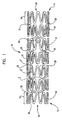
FIG. 1 is a perspective view of an embodiment of the invention. -
FIG. 2 is an expanded view of a portion 2 of the embodiment ofFIG. 1 . -
FIG. 2A is an expanded view of a portion 2 of the embodiment ofFIG. 1 . -
FIG. 3 is an expanded view of a portion 2 of the embodiment ofFIG. 1 in its expanded state. -
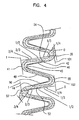
FIG. 4 is an expanded view of a portion of the embodiment ofFIG. 1 . -
FIG. 5 is a partial view illustrating an embodiment of the invention. -
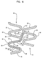
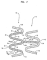
FIG. 6 is a partial view illustrating an example which does not form a part of the invention as claimed. -
FIG. 7 is a partial view illustrating an example which does not form a part of the invention as claimed. - While this invention may be embodied in many different forms, there are described in detail herein specific embodiments of the invention. This description is an exemplification of the principles of the invention and is not intended to limit the invention to the particular embodiments illustrated.
- For the purposes of this disclosure, like reference numerals in the figures shall refer to like features unless otherwise indicated.
- Depicted in the figures are various aspects of the invention. Elements depicted in one figure may be combined with, or substituted for, elements depicted in another figure as desired.
- In one embodiment, as shown in
FIG. 1 , the invention is directed to a stent, shown generally at 10, having aproximal end 12 and a distal end 14, and comprising a plurality of axially spacedserpentine bands 18. Eachserpentine band 18 is shaped in a tubular form forming a plurality ofexpansion columns 19. Eachserpentine band 18, and therefore eachexpansion column 19, is connected to a longitudinally adjacentserpentine band 18 via a plurality of interconnecting struts 20. The interconnecting struts shown are of substantially the same length and arranged in a uniform patter. However, it should be understood that the interconnecting struts 20 may vary in design, number, length and pattern. - A plurality of cells 31 are defined by longitudinally adjacent
serpentine bands 18 and circumferentially adjacent interconnecting struts 20. It should be understood that the shape of the cells vary and the cell pattern may be uniform or irregular. - The
serpentine bands 18 comprise struts 22 circumferentially arranged around thelongitudinal axis 24 of thestent 10.Adjacent struts 22 are connected to one another forming alternatingpeaks 26 andtroughs 28. Since thejunctures 30 betweenadjacent struts 22 could be considered to form apeak 26 and atrough 28 from a top view, the alternatingpeaks 26 andtroughs 28 characteristic should be considered from a proximal end to a distal end or a distal end to a proximal end perspective. It should be understood that the present invention contemplates other generally serpentine configurations and not just the exact configuration shown. - The
stent 10 has a contracted condition, as shown infigure 1 , and an expanded condition. When thestent 10 is expanded, the diameters of theexpansion columns 19 increase, the distance between circumferentiallyadjacent peaks 26 increases and the troughs become more obtuse. -
Figure 2 is an expanded view of a portion 2 of the stent offigure 1 . As can be seen from this illustration of a portion of a non-expandedserpentine band 18, theserpentine bands 18 further include intra-columnar cells (ICC) 36. The ICC's 36 are intra-columnar in that they are within theserpentine band 18 as opposed to between thebands 18, as with cells 31. The ICC's 36 are visible infigure 2 , however it should be understood that, when thestent 10 is in its unexpanded state, as shown infigure 2 , the framework that defines andICC 36 is contracted to such an extent that the ICC's 36 constituteslits 40 comprising very little or no open space. Theseslits 40 are long narrow non-linear cuts or openings fully through theserpentine bands 18 separatingadjacent segments 52/54 of astrut 22. As mentioned above, theslits 40 may comprise a visual opening, but may be closed down to such an extent that thesegments 52/54 of aparticular strut 22 that partially define aslit 40 touch one another. They may be formed by cutting, for example laser cutting, or by any other suitable manner. - As shown in
figure 2 , when thestent 10 is in its contracted state, the ICC's 36 areslits 40. Theslits 40 have afirst end 42 continuously extending to asecond end 44. In the embodiment shown infigure 2 , within a singleserpentine band 18, thefirst end 42 of theslit 40 starts in afirst strut 46, continues in an adjacentsecond strut 48 and terminates at thesecond end 44 in a consecutivethird strut 50. Theslits 40 take on a backward or forward "S" shape as viewed when thestent 10 is horizontal, as shown infigure 1 . In some embodiments, the pattern along the serpentine band is an alternating pattern of backward and forward "S" shapes. -
Figure 4 shows a portion of aserpentine band 18 withfirst strut 46,second strut 48 andthird strut 50. Theslit 40 shown infigure 4 is a forward "S" shape as opposed to the backward "S" shape shown infigure 2-3 . The description is the same, differing only in that it is a mirror image. Theslit 40 extends from itsfirst end 42 instrut 46 to itssecond end 44 instrut 50. Aruler 101 is shown extending from afirst end 39 ofstrut 46 to asecond end 41. Theruler 101 is position parallel withsegment 54 of thestrut 46. Aruler 103 is also shown extending from afirst end 55 ofstrut 50 to asecond end 57. Theruler 103 is position parallel withsegment 52 of thestrut 50. - Both
rulers ends rulers - In the embodiment shown, using the
rulers slit 40 starts 42 in the first 1/3 ofstrut 46 and ends 44 in the last 1/3 ofstrut 50. Specifically, thestart 42 point is between about % and about 1/3 ofstrut 46 and theend 44 is between about 2/3 and about ¾ ofstrut 50. In some embodiments, theslit 40 may start 42 in the first 1/4 (between and including 0 and 1/4) ofstrut 46 and may end 44 in the last 1/4 (between and including 3/4 and 1) ofstrut 50. In some embodiments, theslit 40 may start 42 in the first 1/3 (between and including 0 and 1/3) ofstrut 46 and may end 44 in the last 1/3 (between and including 2/3 and 1) ofstrut 50. In some embodiments, theslit 40 may start 42 in the first ½ (between and including 0 and ½) ofstrut 46 and may end 44 in the last ½ (between and including ½ and 1) ofstrut 50. In some embodiments, theslit 40 may start 42 in the first 2/3 (between and including 0 and 2/3) ofstrut 46 and may end 44 in the last 2/3 (between and including 1/3 and 1) ofstrut 50. In some embodiments, theslit 40 may start 42 between the first ¼ and final ¼ (between and including ¼ and 3/4) ofstrut 46 and may end 44 between the first ¼ and final 1/4 (between and including 1/4 and 3/4) ofstrut 50. - The present invention also contemplates different combinations of the starting 42 and ending 44 points mentioned above. For example, in some embodiments, the
slit 40 may start in the first 1/3 (between and including 0 and 1/3) ofstrut 46 and may end 44 in the last ½ (between and including ½ and 1) ofstrut 50, etc. The invention also contemplates startingpoints 42 and endingpoints 44 between and including the specific individual hash marks shown on therulers ICC 36 can be controlled by adjusting the locations of thestarting point 42 and endingpoint 44 of theslit 40. - The
slit 40, shown infigure 2 , splits the first 46, second 48 and third 50 struts into respective first 52 and second 54 segments. When thestent 10 is in its non-expanded form, as shown infigure 2 , eachfirst segment 52 is immediately adjacent to its correspondingsecond segment 54. Eachserpentine band 18 may contain a plurality ofslits 40. In some embodiments, theslits 40 may be uniformly arranged and, in some embodiments, theslits 40 may be arranged in a non-uniform manner. A non-limiting example of a pattern ofslits 40 of an embodiment of the invention is shown infigure 5 . It should be understood that the pattern may vary. -
Figure 2A is identical tofigure 2 except that it is slightly enlarged for further illustration. In thisfigure 2A , primary hinge points 60 are shown in theserpentine band 18 along theslit 40. In the embodiment shown, there are six primary hinge points (PHP). As can be seen infigure 2A , afirst PHP 43 is located at the end ofsegment 52 ofstrut 46 at thefirst end 42 of theslit 40. Asecond PHP 45 is located in thetrough 28 betweensegment 52 ofstrut 46 andsegment 52 ofstrut 48. Athird PHP 47 is located in the end ofsegment 52 ofstrut 48 adjacent to the peak 26 betweensegment 52 ofstrut 48 andsegment 52 ofstrut 50.PHP 47 is offset from the apex 27 of the peak 26 on the side ofsegment 52 ofstrut 48. Afourth PHP 49 is located at the end ofsegment 54 ofstrut 50 at thesecond end 44 of theslit 40. Afifth PHP 51 is located in thetrough 28 betweensegment 54 ofstrut 48 andsegment 54 ofstrut 50. And asixth PHP 53 is located in the end ofsegment 54 ofstrut 48 adjacent to the peak 26 betweensegment 54 ofstrut 48 andsegment 54 ofstrut 46.PHP 53 is offset from the apex 27 of the peak 26 on the side ofsegment 54 ofstrut 48. Upon expansion of thestent 10, the segments (52, 54) of the struts (46, 48, 50) associated with theslit 40/ICC 36, rotate around the primary hinge points 60. - The PHP may be thinned spots where plastic deformation may occur upon expansion. Positioning and design of the hinge points may also be designed using Finite Element Analysis to create stress risers that are not readily noticeable to dictate the PHP. The hinge points are located at or near the vertices of the polygon ICC structure. As the ICC structure is enlarged, the vertices of the ICC structure hinge and deform to allow the polygon shape to enlarge.
- Upon radial expansion of the
stent 10, as seen infigure 3 , theICCs 36 increase in area from aslit 40 to afull ICC 36. The arrows infigure 3 show the direction of movement of thesegments struts ICC 36. The lengthening of theserpentine bands 18 in a circumferential direction causes the rotation of thesegments struts - Upon expansion, the resulting
ICC 36 shape is polygonal. The specific inner angle sizes and arrangements may vary upon deployment It will open up as needed per the final deployed diameter. A stent deployed to 5 mm may have greater angles than the same stent deployed to 4 mm. - In some embodiments, the
polygonal ICC 36 has six sides and has two inner reflex angles 72, two inneracute angles 70 and twoinner angles 71 that may be acute, obtuse or right.Inner angles 71 may be about 90 degrees (plus or minus 15 degrees). Although some of the inner "corners" of the ICC polygon are rounded, such as with the inner portions of thepeaks 26 and/orvalleys 28, they are to be considered to be inner corners of a polygon. - As can be seen in
figure 3 , upon expansion of thestent 10, thesegments struts serpentine band 18 relative to their positions when thestent 10 is in an unexpanded state, such as infigure 2 . When the stent is expanded and the ICC's 36 are expanded, as shown infigure 3 , thefirst segment 52 ofstrut 46 and thesecond segment 54 ofstrut 50 are largely aligned with theserpentine band 18. In this, it is meant that they are at an angle 81 of less than 45° with theaxis 80 of the serpentine band. Also, when the ICC's 36 are fully expanded, thejuncture 83 betweensegment 52 ofstrut 46 andsegment 52 ofstrut 48 and thejuncture 85 betweensegment 54 ofstrut 48 andsegment 54 ofstrut 50 are substantially aligned with theaxis 80 of theserpentine band 18. - Also, as can be seen in
figure 3 ,segment 52 ofstrut 46 is substantially parallel with and distal to (relative to the length of the stent)segment 54 ofstrut 50.Segment 54 ofstrut 46 is substantially parallel withsegment 52 ofstrut 50 andsegments strut 48 are substantially parallel to one another. In some embodiments, these relative positions are substantially maintained from the ICC's 36 unexpanded state, as shown infigure 2 , to their expanded state, as shown infigure 3 . - In the embodiment shown in the figures, with regard to the linear portions of the segments,
segment 52 ofstrut 46 andsegment 54 ofstrut 50 are substantially the same length and are both shorter than the remaining segments ofstruts Segments strut 48 may be substantially the same length andsegment 54 ofstrut 46 andsegment 52 ofstrut 50 may be substantially the same length. - In some embodiments of the inventive stent, as shown in
figure 3 ,segment 52 ofstrut 46 andsegment 54 ofstrut 50 have widths that are less than that of their corresponding paired segments. The widths of bothsegments struts segments strut 48 may have widths that inversely vary along their linear portion lengths.Segment 52 ofstrut 48 increases in width from its connection withsegment 52 ofstrut 46 to its connection tosegment 52 ofstrut 50 andsegment 54 inversely decreases in width from its connection tosegment 54 ofstrut 46 to its connection tosegment 54 ofstrut 50. The invention also contemplates theses various thickness designs withoutnoticeable hinge 60 thinning. The parameters may be designed to optimize the opening characteristics of the ICC structure and dependant upon the specifics of the particular stent design and ICC structure which is incorporated into the stent. - In an example which does not form a part of the invention as claimed, as shown in
figure 6 , instead of thefirst end 42 of aslit 40 being located in thefirst strut 46, it 42 is located in a interconnectingstrut 20. The interconnectingstrut 20 is measured from the apex 127 of thepeak 26 of theadjacent band 18 to which the interconnectingstrut 20 is connected to the apex 227 of the peak 26 that is formed from thefirst strut 46 and thesecond strut 48. The length of the interconnectingstrut 20 is defined by the distance betweenapex 127 andapex 227. In some embodiments, thefirst end 42 is located in the first half of the interconnectingstrut 20 starting atapex 127. In some examples, thefirst end 42 is located in the first third of the interconnectingstrut 20 starting atapex 127. The ending 44 positioning of theslit 40 may be as described above in reference tofigure 4 . - In an example which does not form a part of the invention as claimed, as shown in
figure 7 , theslit 40, as shown and measured infigure 4 , may extend into an interconnectingstrut 20 to athird end 142. In this particular embodiment, the interconnectingstrut 20 is a peak 226 to trough orvalley 128 interconnecting strut, however it could be a peak to peak strut. Although theslit 40 may terminate 44 in thethird strut 50, as shown infigure 4 , in some examples, as shown infigure 7 , it 40 may extend into afourth strut 75. The location of thesecond end 44 in this case is positioned in thefourth strut 75 at the same place that it would be in thethird strut 50, as described above in reference tofigure 4 . - In the example which does not form a part of the invention shown in
figure 7 , the interconnectingstrut 20 is measured from thevalley 128 of theadjacent band 118 to which the interconnectingstrut 20 is connected to thevirtual apex 327 of the peak 26 that is formed from thesecond strut 48 and thethird strut 50. It should be understood that in some examples that the interconnectingstrut 20 may extend from the peak 26 that is formed from the first 46 and second 48 struts and that in some examples that the interconnectingstrut 20 may extend from the peak 26 that is formed from the third 50 and fourth 75 struts. The length of the interconnectingstrut 20 is defined by the distance between thevalley 128 of theadjacent band 118 to thevirtual apex 327. In some examples, thethird end 142 is located in the first half of the interconnectingstrut 20 starting at thevalley 128. In some examples, thethird end 142 is located in the first third of the interconnectingstrut 20 starting atvalley 128. - The present invention also contemplates stents having any, some or all of the
slit 40 designs within the scope of the appended claims described herein. - In the above discussed embodiments, the inventive stents are of substantially uniform diameter. It is also possible to modify the stent patterns discussed above to prepare stents of non-constant diameter. For example, stent which taper in the expanded state may be made by decreasing the amplitude of the serpentine bands from one end of the stent to the other, or just along a desired portion of the stent. A tapered portion may be provided anywhere along the stent. For example, half of the stent, starting at one end of the stent, may be provided with a taper. Another way to achieve a tapered expanded stent is to change the stiffness of the serpentine bands and/or the connectors such that the stiffness of the serpentine bands and/or connectors varies along the length of the stent. The stiffness of the serpentine bands and/or connectors can be changed by altering length, width or thickness, adding additional stiffening material, using a chemical or mechanical means to alter the physical properties of the stent material, or applying one or a series of elastic elements about the stent
- The inventive stent patterns disclosed herein may also be used in conjunction with other known stent designs to provide stents whose properties vary over the length or portions thereof The inventive slit patterns may also be used in non-serpentine stent designs, such as helix design, tri-bonate design, etc example which does not form a part of the invention.
- The disclosure provides examples of methods of manufacturing a stent according to the designs disclosed herein (not part of the invention as claimed). The disclosure further provides examples of methods of delivering and expanding a stent as described herein (not part of the invention as claimed).
- The inventive stents may be made from any suitable biocompatible materials including one or more polymers, one or more metals or combinations of polymer(s) and metal(s). Examples of suitable materials include biodegradable materials that are also biocompatible. By biodegradable is meant that a material will undergo breakdown or decomposition into harmless compounds as part of a normal biological process. Suitable biodegradable materials include polylactic acid, polyglycolic acid (PGA), collagen or other connective proteins or natural materials, polycaprolactone, hylauric acid, adhesive proteins, co-polymers of these materials as well as composites and combinations thereof and combinations of other biodegradable polymers. Other polymers that may be used include polyester and polycarbonate copolymers. Examples of suitable metals include, but are not limited to, stainless steel, titanium, tantalum, platinum, tungsten, gold and alloys of any of the above-mentioned metals. Examples of suitable alloys include platinum-iridium alloys, cobalt-chromium alloys including Elgiloy and Phynox, MP35N alloy and nickel-titanium alloys, for example, Nitinol.
- The inventive stents may be made of shape memory materials such as superelastic Nitinol or spring steel, or may be made of materials that are plastically deformable. In the case of shape memory materials, the stent may be provided with a memorized shape and then deformed to a reduced diameter shape. The stent may restore itself to its memorized shape upon being heated to a transition temperature and having any restraints removed therefrom.
- The present invention may be incorporated into both of the two basic types of catheters used in combination with a guide wire, commonly referred to as over-the-wire (OTW) catheters and rapid-exchange (RX) catheters. The construction and use of both over-the-wire and rapid-exchange catheters are well known in the art.
- In some examples, the stent, the delivery system or other portion of the assembly may include one or more areas, bands, coatings, members, etc. that is (are) detectable by imaging modalities such as X-Ray, MRI, ultrasound, etc. In some examples at least a portion of the stent and/or adjacent assembly is at least partially radiopaque.
- In some embodiments, at least a portion of the stent is configured to include one or more mechanisms for the delivery of a therapeutic agent Often the agent will be in the form of a coating or other layer (or layers) of material placed on a surface region of the stent, which is adapted to be released at the site of the.stent's implantation or areas adjacent thereto.
- A therapeutic agent may be a drug or other pharmaceutical product such as non-genetic agents, genetic agents, cellular material, etc. Some examples of suitable non-genetic therapeutic agents include but are not limited to: anti-thrombogenic agents such as heparin, heparin derivatives, vascular cell growth promoters, growth factor inhibitors, Paclitaxel, etc. Where an agent includes a genetic therapeutic agent, such a genetic agent may include but is not limited to: DNA, RNA and their respective derivatives and/or components; hedgehog proteins, etc. Where a therapeutic agent includes cellular material, the cellular material may include but is not limited to: cells of human origin and/or non-human origin as well as their respective components and/or derivatives thereof. Where the therapeutic agent includes a polymer agent, the polymer agent may be a polystyrene-polyisobutylene-polystyrene triblock copolymer (SIBS), polyethylene oxide, silicone rubber and/or any other suitable substrate.
- The inventive stents may further comprise a polymer coating in addition to or in place of the therapeutic coating. Suitable polymer coating materials include polycarboxylic acids, cellulosic polymers, including cellulose acetate and cellulose nitrate, gelatin, polyvinylpyrrolidone, cross-linked polyvinylpyrrolidone, polyanhydrides including maleic anhydride polymers, polyamides, polyvinyl alcohols, copolymers of vinyl monomers such as EVA, polyvinyl ethers, polyvinyl aromatics, polyethylene oxides, glycosaminoglycans, polysaccharides, polyesters including polyethylene terephthalate, polyacrylamides, polyethers, polyether sulfone, polycarbonate, polyalkylenes including polypropylene, polyethylene and high molecular weight polyethylene, halogenated polyalkylenes including polytetrafluoroethylene, polyurethanes, polyorthoesters, proteins, polypeptides, silicones, siloxane polymers, polylactic acid, polyglycolic acid, polycaprolactone, polyhydroxybutyrate valerate and blends and copolymers thereof, coatings from polymer dispersions such as polyurethane dispersions, for example, BAYHDROL.RTM., fibrin, collagen and derivatives thereof, polysaccharides such as celluloses, starches, dextrans, alginates and derivatives, hyaluronic acid, squalene emulsions. Polyacrylic acid, available as HYDROPLUS.RTM. (Boston Scientific Corporation, Natick, Mass.), and described in
U.S. Pat No. 5,091,205 is particularly desirable. In a particular desirable example of the invention, the polymer is a copolymer of polylactic acid and polycaprolactone. - In use, the stents disclosed herein are typically delivered via catheter to a desired bodily location. The choice of catheter will depend on the type of stent that is used and on the location to which the stent is delivered.
- Any suitable method may be used to manufacture the inventive stents. For example, in addition to the methods listed above, the inventive stents may also be manufactured by preparing individual portions of the stent and connecting them to one another via welding, the use of adhesives or any other suitable joining technique. This list of manufacturing techniques is not meant to be exhaustive. Other manufacturing techniques may also be used to manufacture the inventive stents.
Claims (10)
- A stent (10) having a proximal end (12), a distal end (14), a longitudinal axis extending through the proximal and distal ends (12, 14) the stent having an unexpanded state and an expanded state, the stent (10) further comprising: a plurality of axially spaced serpentine bands, each serpentine band (18) having an axis circumferentially oriented around the longitudinal axis of the stent (10) and a proximal side and a distal side, each band (18) comprising a plurality of struts, wherein adjacent struts are connected to each other forming a plurality of peaks (26) and troughs (28); a plurality of interconnecting struts (20) axially connecting the serpentine bands (18); and a plurality of cells (31) defined by axially adjacent serpentine bands (18) and circumferentially adjacent interconnecting struts (20), wherein, when the stent (10) is in its unexpanded state, each serpentine band (18) comprises a plurality of slits (40), upon expansion of the stent to its expanded state, each of the slits expands in size to form an intra-columnar cell (ICC), the proximal side and the distal side of the serpentine band (18) being bisected by the axis of the serpentine band, wherein the plurality of struts (22) are spaced along the axis of the serpentine band and wherein the peaks (26) have apex points (27) and the troughs (28) have center points, said peaks and troughs facing distally and proximally in an alternating manner, characterized in that each slit (40) is non-linear and continuous from a first end (42) to a second end (44) and being formed in at least a portion of each of three consecutively connected struts (46, 48, 50), the three consecutively connected struts comprise a first strut (46), a second strut (48) and third strut (50), the first, second and third struts each having a first end and a second end, wherein the second end of the first strut is connected to the first end of the second strut and the second end of the second strut is connected to the first end of the third strut and in that the first end (42) of the slit (40) is positioned in the first strut (46) and the second end of the slit (40) is positioned in the third strut
- The stent of claim 1, wherein the slit (40) crosses the axis of the serpentine band at least three times.
- The stent of claim 1, each of the first, second and third struts having a first segment (52) and a second segment (54), wherein the slit (40) separates the first segment and second segment of the each of the first, second and third struts.
- The stent of claim 3, wherein the first segment (52) of the first strut (46) is connected to the first segment (52) of the second strut (48) forming a trough (28), the first segment of the second strut (48) is connected to the first segment of the third strut (50) forming a peak (26), the second segment of the first strut (46) is connected to the second segment of the second strut (48) forming a peak (26) and the second segment of the second strut (48) is connected to the second segment of the third strut (50) forming a trough (28).
- The stent of claim 1 or 4, wherein the ICC (36) is substantially a polygon and has at least two inner reflex angles.
- The stent of claim 5, wherein the ICC (36) has at least two inner acute angles.
- The stent of claim 5, wherein the second segment of the first strut is substantially parallel with the first segment of the third strut and wherein the first segment of the second strut is substantially parallel with the second segment of the second strut.
- The stent of claim 4, wherein the second segment of the first strut and the first segment of the third strut have greater widths than the first segment of the first strut and the second segment of the third strut.
- The stent of claim 5, the serpentine bands (18) further comprising a plurality of primary hinge points (60), wherein, upon expansion of the stent (10) and the forming of the ICC (36), the first and second segments of the firsts second and third struts (46, 48, 50) rotate around the primary hinge points (60), increasing the size of the slit (40) to form the ICC.
- The stent of claim 1, wherein the stent further comprises a therapeutic agent.
Applications Claiming Priority (3)
| Application Number | Priority Date | Filing Date | Title |
|---|---|---|---|
| US84387306P | 2006-09-12 | 2006-09-12 | |
| US11/844,583 US20080065196A1 (en) | 2006-09-12 | 2007-08-24 | Intra-Columnar Cell Features to Improve Drug Distribution and Scaffolding of a Stent |
| PCT/US2007/019363 WO2008033245A1 (en) | 2006-09-12 | 2007-09-05 | Intra-columnar cell features to improve drug distribution and scaffolding of a stent |
Publications (2)
| Publication Number | Publication Date |
|---|---|
| EP2068762A1 EP2068762A1 (en) | 2009-06-17 |
| EP2068762B1 true EP2068762B1 (en) | 2012-06-27 |
Family
ID=38920707
Family Applications (1)
| Application Number | Title | Priority Date | Filing Date |
|---|---|---|---|
| EP07837742A Not-in-force EP2068762B1 (en) | 2006-09-12 | 2007-09-05 | Intra-columnar cell features to improve drug distribution and scaffolding of a stent |
Country Status (5)
| Country | Link |
|---|---|
| US (1) | US20080065196A1 (en) |
| EP (1) | EP2068762B1 (en) |
| JP (1) | JP5185273B2 (en) |
| CA (1) | CA2661341A1 (en) |
| WO (1) | WO2008033245A1 (en) |
Families Citing this family (11)
| Publication number | Priority date | Publication date | Assignee | Title |
|---|---|---|---|---|
| US20090240318A1 (en) * | 2008-03-19 | 2009-09-24 | Boston Scientific Scimed, Inc. | Stent expansion column, strut and connector slit design |
| US20100049307A1 (en) * | 2008-08-25 | 2010-02-25 | Aga Medical Corporation | Stent graft having extended landing area and method for using the same |
| US20100082096A1 (en) * | 2008-09-30 | 2010-04-01 | Boston Scientific Scimed, Inc. | Tailored Luminal & Abluminal Drug Elution |
| DE102009010825B4 (en) * | 2009-02-26 | 2011-03-31 | Acandis Gmbh & Co. Kg | Medical implant with a lattice structure, method for its production and method for introducing the medical implant into a delivery system |
| US20100292777A1 (en) * | 2009-05-13 | 2010-11-18 | Boston Scientific Scimed, Inc. | Stent |
| US20110137407A1 (en) * | 2009-07-09 | 2011-06-09 | Thai Minh Nguyen | Bare metal stent with drug eluting reservoirs |
| US8114149B2 (en) * | 2009-10-20 | 2012-02-14 | Svelte Medical Systems, Inc. | Hybrid stent with helical connectors |
| CN102525701B (en) * | 2010-12-21 | 2015-06-17 | 先健科技(深圳)有限公司 | Absorbable blood vessel stent |
| US9381103B2 (en) * | 2014-10-06 | 2016-07-05 | Abbott Cardiovascular Systems Inc. | Stent with elongating struts |
| WO2016144096A1 (en) | 2015-03-12 | 2016-09-15 | 재단법인 유타 인하 디디에스 및 신의료기술개발 공동연구소 | Stent having functional material coated on cell space thereof |
| DE102016117398B4 (en) | 2016-09-15 | 2023-07-13 | Universität Rostock | Expandable structure |
Family Cites Families (13)
| Publication number | Priority date | Publication date | Assignee | Title |
|---|---|---|---|---|
| US3120336A (en) * | 1960-03-09 | 1964-02-04 | Du Pont | Pouch |
| US5091205A (en) | 1989-01-17 | 1992-02-25 | Union Carbide Chemicals & Plastics Technology Corporation | Hydrophilic lubricious coatings |
| US5843120A (en) * | 1994-03-17 | 1998-12-01 | Medinol Ltd. | Flexible-expandable stent |
| WO1996026689A1 (en) | 1995-03-01 | 1996-09-06 | Scimed Life Systems, Inc. | Improved longitudinally flexible expandable stent |
| DE19614160A1 (en) * | 1996-04-10 | 1997-10-16 | Variomed Ag | Stent for transluminal implantation in hollow organs |
| DE19717475C1 (en) * | 1997-04-25 | 1998-09-03 | Heraeus Gmbh W C | Radially expandable support structure or stent for tubular vessel in body |
| US6132461A (en) * | 1998-03-27 | 2000-10-17 | Intratherapeutics, Inc. | Stent with dual support structure |
| AU1084101A (en) * | 1999-10-14 | 2001-04-23 | United Stenting, Inc. | Stents with multilayered struts |
| US6440162B1 (en) * | 2000-07-26 | 2002-08-27 | Advanced Cardiovascular Systems, Inc. | Stent having increased scaffolding expandable bar arms |
| DE60124285T3 (en) * | 2000-09-29 | 2011-03-17 | Cordis Corp., Miami Lakes | COATED MEDICAL EQUIPMENT |
| US7014654B2 (en) * | 2001-11-30 | 2006-03-21 | Scimed Life Systems, Inc. | Stent designed for the delivery of therapeutic substance or other agents |
| US7090694B1 (en) * | 2003-11-19 | 2006-08-15 | Advanced Cardiovascular Systems, Inc. | Portal design for stent for treating bifurcated vessels |
| JP4797473B2 (en) * | 2005-07-11 | 2011-10-19 | ニプロ株式会社 | Flexible stent with excellent expandability |
-
2007
- 2007-08-24 US US11/844,583 patent/US20080065196A1/en not_active Abandoned
- 2007-09-05 WO PCT/US2007/019363 patent/WO2008033245A1/en active Application Filing
- 2007-09-05 CA CA002661341A patent/CA2661341A1/en not_active Abandoned
- 2007-09-05 JP JP2009527393A patent/JP5185273B2/en not_active Expired - Fee Related
- 2007-09-05 EP EP07837742A patent/EP2068762B1/en not_active Not-in-force
Also Published As
| Publication number | Publication date |
|---|---|
| CA2661341A1 (en) | 2008-03-20 |
| JP5185273B2 (en) | 2013-04-17 |
| US20080065196A1 (en) | 2008-03-13 |
| JP2010503427A (en) | 2010-02-04 |
| EP2068762A1 (en) | 2009-06-17 |
| WO2008033245A1 (en) | 2008-03-20 |
Similar Documents
| Publication | Publication Date | Title |
|---|---|---|
| EP2068762B1 (en) | Intra-columnar cell features to improve drug distribution and scaffolding of a stent | |
| EP2043567B1 (en) | Stent design with variable expansion columns along circumference | |
| EP2059199B1 (en) | Longitudinally flexible expandable stent | |
| US8016878B2 (en) | Bifurcation stent pattern | |
| US8512392B2 (en) | Stent design with struts of various angles and stiffness | |
| EP1954223B1 (en) | Stent configurations | |
| US8317855B2 (en) | Crimpable and expandable side branch cell | |
| EP2063809B1 (en) | Stent having end section with constant strut lengths, transitional section and middle section with variable strut lengths | |
| US7988720B2 (en) | Longitudinally flexible expandable stent | |
| US7537608B2 (en) | Stent with variable crimping diameter | |
| EP2086475B1 (en) | Bifurcated stent | |
| US20070225798A1 (en) | Side branch stent | |
| JP2008541841A (en) | Initiation geometry of stent side branch | |
| EP1993488A1 (en) | Bifurcated stent with surface area gradient |
Legal Events
| Date | Code | Title | Description |
|---|---|---|---|
| PUAI | Public reference made under article 153(3) epc to a published international application that has entered the european phase |
Free format text: ORIGINAL CODE: 0009012 |
|
| 17P | Request for examination filed |
Effective date: 20090326 |
|
| AK | Designated contracting states |
Kind code of ref document: A1 Designated state(s): AT BE BG CH CY CZ DE DK EE ES FI FR GB GR HU IE IS IT LI LT LU LV MC MT NL PL PT RO SE SI SK TR |
|
| AX | Request for extension of the european patent |
Extension state: AL BA HR MK RS |
|
| 17Q | First examination report despatched |
Effective date: 20101118 |
|
| GRAP | Despatch of communication of intention to grant a patent |
Free format text: ORIGINAL CODE: EPIDOSNIGR1 |
|
| DAX | Request for extension of the european patent (deleted) | ||
| GRAS | Grant fee paid |
Free format text: ORIGINAL CODE: EPIDOSNIGR3 |
|
| GRAA | (expected) grant |
Free format text: ORIGINAL CODE: 0009210 |
|
| AK | Designated contracting states |
Kind code of ref document: B1 Designated state(s): AT BE BG CH CY CZ DE DK EE ES FI FR GB GR HU IE IS IT LI LT LU LV MC MT NL PL PT RO SE SI SK TR |
|
| REG | Reference to a national code |
Ref country code: GB Ref legal event code: FG4D |
|
| REG | Reference to a national code |
Ref country code: CH Ref legal event code: EP |
|
| REG | Reference to a national code |
Ref country code: AT Ref legal event code: REF Ref document number: 563717 Country of ref document: AT Kind code of ref document: T Effective date: 20120715 |
|
| REG | Reference to a national code |
Ref country code: IE Ref legal event code: FG4D |
|
| REG | Reference to a national code |
Ref country code: DE Ref legal event code: R096 Ref document number: 602007023703 Country of ref document: DE Effective date: 20120823 |
|
| PG25 | Lapsed in a contracting state [announced via postgrant information from national office to epo] |
Ref country code: LT Free format text: LAPSE BECAUSE OF FAILURE TO SUBMIT A TRANSLATION OF THE DESCRIPTION OR TO PAY THE FEE WITHIN THE PRESCRIBED TIME-LIMIT Effective date: 20120627 Ref country code: SE Free format text: LAPSE BECAUSE OF FAILURE TO SUBMIT A TRANSLATION OF THE DESCRIPTION OR TO PAY THE FEE WITHIN THE PRESCRIBED TIME-LIMIT Effective date: 20120627 Ref country code: FI Free format text: LAPSE BECAUSE OF FAILURE TO SUBMIT A TRANSLATION OF THE DESCRIPTION OR TO PAY THE FEE WITHIN THE PRESCRIBED TIME-LIMIT Effective date: 20120627 |
|
| REG | Reference to a national code |
Ref country code: NL Ref legal event code: VDEP Effective date: 20120627 |
|
| REG | Reference to a national code |
Ref country code: AT Ref legal event code: MK05 Ref document number: 563717 Country of ref document: AT Kind code of ref document: T Effective date: 20120627 |
|
| REG | Reference to a national code |
Ref country code: LT Ref legal event code: MG4D Effective date: 20120627 |
|
| PG25 | Lapsed in a contracting state [announced via postgrant information from national office to epo] |
Ref country code: SI Free format text: LAPSE BECAUSE OF FAILURE TO SUBMIT A TRANSLATION OF THE DESCRIPTION OR TO PAY THE FEE WITHIN THE PRESCRIBED TIME-LIMIT Effective date: 20120627 Ref country code: LV Free format text: LAPSE BECAUSE OF FAILURE TO SUBMIT A TRANSLATION OF THE DESCRIPTION OR TO PAY THE FEE WITHIN THE PRESCRIBED TIME-LIMIT Effective date: 20120627 Ref country code: GR Free format text: LAPSE BECAUSE OF FAILURE TO SUBMIT A TRANSLATION OF THE DESCRIPTION OR TO PAY THE FEE WITHIN THE PRESCRIBED TIME-LIMIT Effective date: 20120928 |
|
| PG25 | Lapsed in a contracting state [announced via postgrant information from national office to epo] |
Ref country code: AT Free format text: LAPSE BECAUSE OF FAILURE TO SUBMIT A TRANSLATION OF THE DESCRIPTION OR TO PAY THE FEE WITHIN THE PRESCRIBED TIME-LIMIT Effective date: 20120627 Ref country code: IS Free format text: LAPSE BECAUSE OF FAILURE TO SUBMIT A TRANSLATION OF THE DESCRIPTION OR TO PAY THE FEE WITHIN THE PRESCRIBED TIME-LIMIT Effective date: 20121027 Ref country code: BE Free format text: LAPSE BECAUSE OF FAILURE TO SUBMIT A TRANSLATION OF THE DESCRIPTION OR TO PAY THE FEE WITHIN THE PRESCRIBED TIME-LIMIT Effective date: 20120627 Ref country code: SK Free format text: LAPSE BECAUSE OF FAILURE TO SUBMIT A TRANSLATION OF THE DESCRIPTION OR TO PAY THE FEE WITHIN THE PRESCRIBED TIME-LIMIT Effective date: 20120627 Ref country code: RO Free format text: LAPSE BECAUSE OF FAILURE TO SUBMIT A TRANSLATION OF THE DESCRIPTION OR TO PAY THE FEE WITHIN THE PRESCRIBED TIME-LIMIT Effective date: 20120627 Ref country code: EE Free format text: LAPSE BECAUSE OF FAILURE TO SUBMIT A TRANSLATION OF THE DESCRIPTION OR TO PAY THE FEE WITHIN THE PRESCRIBED TIME-LIMIT Effective date: 20120627 Ref country code: CZ Free format text: LAPSE BECAUSE OF FAILURE TO SUBMIT A TRANSLATION OF THE DESCRIPTION OR TO PAY THE FEE WITHIN THE PRESCRIBED TIME-LIMIT Effective date: 20120627 Ref country code: CY Free format text: LAPSE BECAUSE OF FAILURE TO SUBMIT A TRANSLATION OF THE DESCRIPTION OR TO PAY THE FEE WITHIN THE PRESCRIBED TIME-LIMIT Effective date: 20120627 |
|
| PG25 | Lapsed in a contracting state [announced via postgrant information from national office to epo] |
Ref country code: IT Free format text: LAPSE BECAUSE OF FAILURE TO SUBMIT A TRANSLATION OF THE DESCRIPTION OR TO PAY THE FEE WITHIN THE PRESCRIBED TIME-LIMIT Effective date: 20120627 Ref country code: PL Free format text: LAPSE BECAUSE OF FAILURE TO SUBMIT A TRANSLATION OF THE DESCRIPTION OR TO PAY THE FEE WITHIN THE PRESCRIBED TIME-LIMIT Effective date: 20120627 Ref country code: PT Free format text: LAPSE BECAUSE OF FAILURE TO SUBMIT A TRANSLATION OF THE DESCRIPTION OR TO PAY THE FEE WITHIN THE PRESCRIBED TIME-LIMIT Effective date: 20121029 |
|
| PG25 | Lapsed in a contracting state [announced via postgrant information from national office to epo] |
Ref country code: NL Free format text: LAPSE BECAUSE OF FAILURE TO SUBMIT A TRANSLATION OF THE DESCRIPTION OR TO PAY THE FEE WITHIN THE PRESCRIBED TIME-LIMIT Effective date: 20120627 |
|
| PG25 | Lapsed in a contracting state [announced via postgrant information from national office to epo] |
Ref country code: DK Free format text: LAPSE BECAUSE OF FAILURE TO SUBMIT A TRANSLATION OF THE DESCRIPTION OR TO PAY THE FEE WITHIN THE PRESCRIBED TIME-LIMIT Effective date: 20120627 Ref country code: ES Free format text: LAPSE BECAUSE OF FAILURE TO SUBMIT A TRANSLATION OF THE DESCRIPTION OR TO PAY THE FEE WITHIN THE PRESCRIBED TIME-LIMIT Effective date: 20121008 Ref country code: MC Free format text: LAPSE BECAUSE OF NON-PAYMENT OF DUE FEES Effective date: 20120930 |
|
| REG | Reference to a national code |
Ref country code: CH Ref legal event code: PL |
|
| PLBE | No opposition filed within time limit |
Free format text: ORIGINAL CODE: 0009261 |
|
| STAA | Information on the status of an ep patent application or granted ep patent |
Free format text: STATUS: NO OPPOSITION FILED WITHIN TIME LIMIT |
|
| GBPC | Gb: european patent ceased through non-payment of renewal fee |
Effective date: 20120927 |
|
| 26N | No opposition filed |
Effective date: 20130328 |
|
| REG | Reference to a national code |
Ref country code: FR Ref legal event code: ST Effective date: 20130531 |
|
| REG | Reference to a national code |
Ref country code: DE Ref legal event code: R097 Ref document number: 602007023703 Country of ref document: DE Effective date: 20130328 |
|
| PG25 | Lapsed in a contracting state [announced via postgrant information from national office to epo] |
Ref country code: GB Free format text: LAPSE BECAUSE OF NON-PAYMENT OF DUE FEES Effective date: 20120927 Ref country code: BG Free format text: LAPSE BECAUSE OF FAILURE TO SUBMIT A TRANSLATION OF THE DESCRIPTION OR TO PAY THE FEE WITHIN THE PRESCRIBED TIME-LIMIT Effective date: 20120927 Ref country code: CH Free format text: LAPSE BECAUSE OF NON-PAYMENT OF DUE FEES Effective date: 20120930 Ref country code: LI Free format text: LAPSE BECAUSE OF NON-PAYMENT OF DUE FEES Effective date: 20120930 |
|
| PG25 | Lapsed in a contracting state [announced via postgrant information from national office to epo] |
Ref country code: FR Free format text: LAPSE BECAUSE OF NON-PAYMENT OF DUE FEES Effective date: 20121001 |
|
| PGFP | Annual fee paid to national office [announced via postgrant information from national office to epo] |
Ref country code: DE Payment date: 20130829 Year of fee payment: 7 Ref country code: IE Payment date: 20130910 Year of fee payment: 7 |
|
| PG25 | Lapsed in a contracting state [announced via postgrant information from national office to epo] |
Ref country code: MT Free format text: LAPSE BECAUSE OF FAILURE TO SUBMIT A TRANSLATION OF THE DESCRIPTION OR TO PAY THE FEE WITHIN THE PRESCRIBED TIME-LIMIT Effective date: 20120627 |
|
| PG25 | Lapsed in a contracting state [announced via postgrant information from national office to epo] |
Ref country code: TR Free format text: LAPSE BECAUSE OF FAILURE TO SUBMIT A TRANSLATION OF THE DESCRIPTION OR TO PAY THE FEE WITHIN THE PRESCRIBED TIME-LIMIT Effective date: 20120627 |
|
| PG25 | Lapsed in a contracting state [announced via postgrant information from national office to epo] |
Ref country code: LU Free format text: LAPSE BECAUSE OF NON-PAYMENT OF DUE FEES Effective date: 20120905 |
|
| PG25 | Lapsed in a contracting state [announced via postgrant information from national office to epo] |
Ref country code: HU Free format text: LAPSE BECAUSE OF FAILURE TO SUBMIT A TRANSLATION OF THE DESCRIPTION OR TO PAY THE FEE WITHIN THE PRESCRIBED TIME-LIMIT Effective date: 20070905 |
|
| REG | Reference to a national code |
Ref country code: DE Ref legal event code: R082 Ref document number: 602007023703 Country of ref document: DE Representative=s name: KANZLEI PFENNING, MEINIG & PARTNER GBR, DE |
|
| REG | Reference to a national code |
Ref country code: DE Ref legal event code: R082 Ref document number: 602007023703 Country of ref document: DE Representative=s name: KANZLEI PFENNING, MEINIG & PARTNER GBR, DE |
|
| REG | Reference to a national code |
Ref country code: DE Ref legal event code: R081 Ref document number: 602007023703 Country of ref document: DE Owner name: BOSTON SCIENTIFIC LIMITED, BM Free format text: FORMER OWNER: BOSTON SCIENTIFIC LIMITED, CHRIST CHURCH, BB Effective date: 20150202 Ref country code: DE Ref legal event code: R081 Ref document number: 602007023703 Country of ref document: DE Owner name: BOSTON SCIENTIFIC LIMITED, BM Free format text: FORMER OWNER: BOSTON SCIENTIFIC LIMITED, AN IRISH COMPANY, BARBADOS, WEST INDIES, BB Effective date: 20120806 Ref country code: DE Ref legal event code: R082 Ref document number: 602007023703 Country of ref document: DE Representative=s name: KANZLEI PFENNING, MEINIG & PARTNER GBR, DE Effective date: 20140930 Ref country code: DE Ref legal event code: R082 Ref document number: 602007023703 Country of ref document: DE Representative=s name: KANZLEI PFENNING, MEINIG & PARTNER GBR, DE Effective date: 20150202 |
|
| REG | Reference to a national code |
Ref country code: DE Ref legal event code: R119 Ref document number: 602007023703 Country of ref document: DE |
|
| REG | Reference to a national code |
Ref country code: IE Ref legal event code: MM4A |
|
| PG25 | Lapsed in a contracting state [announced via postgrant information from national office to epo] |
Ref country code: DE Free format text: LAPSE BECAUSE OF NON-PAYMENT OF DUE FEES Effective date: 20150401 |
|
| PG25 | Lapsed in a contracting state [announced via postgrant information from national office to epo] |
Ref country code: IE Free format text: LAPSE BECAUSE OF NON-PAYMENT OF DUE FEES Effective date: 20140905 |