JP5184806B2 - Method for producing transparent thermoplastic film and transparent thermoplastic film - Google Patents
Method for producing transparent thermoplastic film and transparent thermoplastic film Download PDFInfo
- Publication number
- JP5184806B2 JP5184806B2 JP2007088851A JP2007088851A JP5184806B2 JP 5184806 B2 JP5184806 B2 JP 5184806B2 JP 2007088851 A JP2007088851 A JP 2007088851A JP 2007088851 A JP2007088851 A JP 2007088851A JP 5184806 B2 JP5184806 B2 JP 5184806B2
- Authority
- JP
- Japan
- Prior art keywords
- group
- film
- stretching
- preferable
- transparent thermoplastic
- Prior art date
- Legal status (The legal status is an assumption and is not a legal conclusion. Google has not performed a legal analysis and makes no representation as to the accuracy of the status listed.)
- Active
Links
Images
Classifications
-
- B—PERFORMING OPERATIONS; TRANSPORTING
- B32—LAYERED PRODUCTS
- B32B—LAYERED PRODUCTS, i.e. PRODUCTS BUILT-UP OF STRATA OF FLAT OR NON-FLAT, e.g. CELLULAR OR HONEYCOMB, FORM
- B32B23/00—Layered products comprising a layer of cellulosic plastic substances, i.e. substances obtained by chemical modification of cellulose, e.g. cellulose ethers, cellulose esters, viscose
-
- C—CHEMISTRY; METALLURGY
- C08—ORGANIC MACROMOLECULAR COMPOUNDS; THEIR PREPARATION OR CHEMICAL WORKING-UP; COMPOSITIONS BASED THEREON
- C08J—WORKING-UP; GENERAL PROCESSES OF COMPOUNDING; AFTER-TREATMENT NOT COVERED BY SUBCLASSES C08B, C08C, C08F, C08G or C08H
- C08J5/00—Manufacture of articles or shaped materials containing macromolecular substances
- C08J5/18—Manufacture of films or sheets
-
- C—CHEMISTRY; METALLURGY
- C08—ORGANIC MACROMOLECULAR COMPOUNDS; THEIR PREPARATION OR CHEMICAL WORKING-UP; COMPOSITIONS BASED THEREON
- C08J—WORKING-UP; GENERAL PROCESSES OF COMPOUNDING; AFTER-TREATMENT NOT COVERED BY SUBCLASSES C08B, C08C, C08F, C08G or C08H
- C08J2301/00—Characterised by the use of cellulose, modified cellulose or cellulose derivatives
- C08J2301/08—Cellulose derivatives
- C08J2301/10—Esters of organic acids
-
- G—PHYSICS
- G02—OPTICS
- G02B—OPTICAL ELEMENTS, SYSTEMS OR APPARATUS
- G02B5/00—Optical elements other than lenses
- G02B5/30—Polarising elements
Landscapes
- Chemical & Material Sciences (AREA)
- Engineering & Computer Science (AREA)
- Manufacturing & Machinery (AREA)
- Materials Engineering (AREA)
- Health & Medical Sciences (AREA)
- Chemical Kinetics & Catalysis (AREA)
- Medicinal Chemistry (AREA)
- Polymers & Plastics (AREA)
- Organic Chemistry (AREA)
- Shaping By String And By Release Of Stress In Plastics And The Like (AREA)
- Polarising Elements (AREA)
- Manufacture Of Macromolecular Shaped Articles (AREA)
Description
本発明は、透明熱可塑性フィルムおよびその製造に関するものである。特に、液晶表示板に組み込み温度変化を与えた時に発現する黒表示時のむらを軽減する透明熱可塑性フィルムおよびその製造方法に関する。 The present invention relates to a transparent thermoplastic film and its production. In particular, the present invention relates to a transparent thermoplastic film that reduces unevenness during black display that occurs when a change in temperature is applied to a liquid crystal display panel, and a method for manufacturing the same.
従来セルロースアシレート等の透明熱可塑性フィルム等の透明熱可塑性樹脂を製膜、延伸して、液晶表示素子の位相差膜として使用し、視野角拡大を図ることが実施されている。特に近年、設備投資を低く抑えることができる溶融製膜法を用い、これを延伸した位相差膜が開発されている。このような位相差膜を達成する方法が下記特許文献1に記載されている。これは特定のレターデーション、ヘイズを有することを特徴とし、大画面の液晶表示装置に組み込み視野角の拡大を達成するものである。しかしこの液晶表示装置は環境の影響を受けやすく、設置環境が高温(例えば30℃)から低温(例えば10℃)に変化すると、画面にむらが発生し改良が望まれていた。このような画像のむらは特に黒表示にした時に顕著に現れた。即ち環境の変化に伴い、液晶表示装置に用いた位相差膜の光学特性が変化し光漏れが発生し、画像むらとなって現れていた。 Conventionally, a transparent thermoplastic resin such as a transparent thermoplastic film such as cellulose acylate is formed and stretched, and used as a retardation film of a liquid crystal display device to increase the viewing angle. In recent years, in particular, a retardation film obtained by using a melt film-forming method capable of keeping the capital investment low has been developed. A method for achieving such a retardation film is described in Patent Document 1 below. This is characterized by having a specific retardation and haze, and is incorporated into a large-screen liquid crystal display device to achieve a wide viewing angle. However, this liquid crystal display device is easily affected by the environment, and when the installation environment changes from a high temperature (for example, 30 ° C.) to a low temperature (for example, 10 ° C.), unevenness occurs on the screen, and improvement has been desired. Such unevenness of the image was particularly noticeable when black display was used. That is, as the environment changes, the optical characteristics of the retardation film used in the liquid crystal display device change and light leakage occurs, resulting in image unevenness.
本発明は、上記課題を解決することを目的としたものであって、液晶表示装置に組み込んだ際、温度変化があっても光学特性が変化しない光学フィルムを提供することを目的とする。 The present invention aims to solve the above-described problems, and an object of the present invention is to provide an optical film whose optical characteristics do not change even when there is a temperature change when incorporated in a liquid crystal display device.
上記課題の下、発明者が鋭意検討を行った結果、以下の方法により達成された。
(1)横延伸ゾーン長(L2)と予熱ゾーン長(L1)の比(L2/L1)が0.5〜30の範囲で、1%〜200%横延伸することを含む、透明熱可塑性フィルムの製造方法。
(2)横延伸ゾーン内の拡幅角を5度〜45度とすることを含む、(1)に記載の透明熱可塑性フィルムの製造方法。
(3)横延伸温度をT1としたとき、横延伸後にT1−50℃〜T1−2℃で熱処理することを含む、(1)または(2)に記載の透明熱可塑性フィルムの製造方法。
(4)横延伸温度をT1としたとき、横延伸前にT1+2℃〜T1+50℃で熱処理することを含む、(1)〜(3)のいずれか1項に記載の透明熱可塑性フィルムの製造方法。
(5)縦/横比(L/W)が0.01を越え0.3未満の範囲、又は2を超え50以下で、1%〜100%に縦延伸することを含む、(1)〜(4)のいずれか1項に記載の透明熱可塑性フィルムの製造方法。
(6)縦延伸後および横延伸後の少なくとも一方において、前記透明熱可塑性フィルムのガラス転移温度をTgとしたとき、Tg−30℃〜Tg+30℃の温度範囲において、縦方向および横方向の緩和量の合計が1%〜20%となるように緩和することを含む、(1)〜(5)のいずれか1項に記載の透明熱可塑性フィルムの製造方法。
(7)タッチロールを用いて溶融製膜することを含む、(1)〜(6)のいずれか1項に記載の透明熱可塑性フィルムの製造方法。
(8)透明熱可塑性フィルムであって、該フィルムの一辺30cmの正方形の内部の熱収縮分布および弾性率分布がいずれも10%以下である透明熱可塑性フィルム。
(9)横延伸ゾーン長(L2)と予熱ゾーン長(L1)の比(L2/L1)が0.5〜30の範囲で、1%〜200%横延伸してなる、(8)に記載の透明可塑性フィルム。
(10)(8)または(9)に記載の透明熱可塑性フィルムであって、該フィルムの幅全域に亘り配向角が0°±5°以内、または90°±5°以内である、透明熱可塑性フィルム。
(11)面内のレターデーション(Re)が20nm〜400nm、厚み方向のレターデーション(Rth)が50nm〜400nmである、(8)〜(10)のいずれか1項に記載の透明熱可塑性フィルム。
(12)下記式を満足するセルロースアシレートを含む、(8)〜(11)のいずれか1項に記載の透明熱可塑性フィルム。
2.0≦A+B<3.0
0.1≦B<3
A:アセテート基の置換度、
B:プロピオネート基、ブチレート基、ペンタノイル基の置換度の総和
(13)下記式(T−1)および(T−2)を満たす組成を有するセルロースアシレートからなることを特徴とする(8)〜(12)のいずれか1項に記載の熱可塑性フィルム。
式(T−1):2.5≦A+C<3.0
式(T−2):0.1≦C<2
(式中、Aは、アセテート基の置換度を示し、Cは置換もしくは無置換の芳香族アシル基を示す。)
(14)飽和ノルボルネン樹脂を含む、(8)〜(13)のいずれか1項に記載の透明熱可塑性フィルム。
(15)残留溶剤が0.01質量%以下である、(8)〜(14)のいずれか1項に記載の透明熱可塑性フィルム。
As a result of intensive studies by the inventor under the above problems, the present invention has been achieved by the following method.
(1) The ratio of the transverse stretching zone length (L 2 ) to the preheating zone length (L 1 ) (L 2 / L 1 ) is in the range of 0.5 to 30, including 1% to 200% transverse stretching. A method for producing a transparent thermoplastic film.
(2) The manufacturing method of the transparent thermoplastic film as described in (1) including making the widening angle in a transverse stretch zone into 5 to 45 degree | times.
(3) Production of a transparent thermoplastic film according to (1) or (2), comprising heat treatment at T 1 −50 ° C. to T 1 −2 ° C. after transverse stretching when the transverse stretching temperature is T 1. Method.
(4) The transparent heat according to any one of (1) to (3), including heat treatment at T 1 + 2 ° C. to T 1 + 50 ° C. before transverse stretching when the transverse stretching temperature is T 1. A method for producing a plastic film.
(5) The longitudinal / lateral ratio (L / W) is in the range of more than 0.01 and less than 0.3, or more than 2 and 50 or less, including longitudinal stretching to 1% to 100%, (1) to (4) The manufacturing method of the transparent thermoplastic film of any one of (4).
(6) After at least one of longitudinal stretching and lateral stretching, when Tg is the glass transition temperature of the transparent thermoplastic film, the amount of relaxation in the longitudinal direction and the transverse direction is within a temperature range of Tg-30 ° C to Tg + 30 ° C. The manufacturing method of the transparent thermoplastic film of any one of (1)-(5) including relaxing so that the sum total may become 1%-20%.
(7) The manufacturing method of the transparent thermoplastic film of any one of (1)-(6) including melt film-forming using a touch roll.
(8) A transparent thermoplastic film having a heat shrinkage distribution and an elastic modulus distribution inside a square of 30 cm on a side of the film, both of which are 10% or less.
(9) in the range ratio (L 2 / L 1) is 0.5 to 30 in the transverse stretching zone length (L 2) and the preheating zone length (L 1), formed by transverse stretching of 1% to 200%, ( The transparent plastic film as described in 8).
(10) The transparent thermoplastic film according to (8) or (9), wherein the orientation angle is within 0 ° ± 5 ° or within 90 ° ± 5 ° over the entire width of the film Plastic film.
(11) The transparent thermoplastic film according to any one of (8) to (10), wherein the in-plane retardation (Re) is 20 nm to 400 nm and the thickness direction retardation (Rth) is 50 nm to 400 nm. .
(12) The transparent thermoplastic film according to any one of (8) to (11), comprising a cellulose acylate satisfying the following formula.
2.0 ≦ A + B <3.0
0.1 ≦ B <3
A: Degree of substitution of acetate group,
B: Total substitution degree of propionate group, butyrate group, pentanoyl group (13) Cellulose acylate having a composition satisfying the following formulas (T-1) and (T-2) (8) to The thermoplastic film according to any one of (12).
Formula (T-1): 2.5 <= A + C <3.0
Formula (T-2): 0.1 ≦ C <2
(In the formula, A represents the degree of substitution of the acetate group, and C represents a substituted or unsubstituted aromatic acyl group.)
(14) The transparent thermoplastic film according to any one of (8) to (13), comprising a saturated norbornene resin.
(15) The transparent thermoplastic film according to any one of (8) to (14), wherein the residual solvent is 0.01% by mass or less.
透明熱可塑性フィルムを延伸した位相差板を液晶表示素子に組み込んだ時、高温、高湿経時後でも色むらの発生しない良好な延伸透明熱可塑性フィルムが得られた。 When a retardation film having a transparent thermoplastic film stretched was incorporated into a liquid crystal display element, a good stretched transparent thermoplastic film having no color unevenness even after high temperature and high humidity was obtained.
以下において、本発明の内容について詳細に説明する。尚、本願明細書において「〜」とはその前後に記載される数値を下限値および上限値として含む意味で使用される。 Hereinafter, the contents of the present invention will be described in detail. In the present specification, “to” is used to mean that the numerical values described before and after it are included as a lower limit value and an upper limit value.
本発明では、液晶表示装置に組み込んだ際に温度変化に伴い発生する画面のむら、即ち液晶表示装置内での位相差膜の光学特性の変化が下記理由により発現することを明らかにした。即ち、位相差膜は偏光子と張り合わせて使用するが、両者の熱膨張係数が異なるため、温度変化に伴い収縮応力が発生し、これにより光学特性(面内のレターデーション(Re)、厚み方向のレターデーション(Rth))が変化する。位相差膜の特性が全面均一であれば液晶表示装置に組み込んだ際にむらとなって認識され難いが、不均一であるとRe,Rthが局所的に変化し、目視でむらとなって認識されやすい。
このようなRe、Rth等の光学特性に影響を与えやすいのが、熱収縮率、弾性率であり、これらはそれぞれ、一辺30cmの正方形内の分布が10%以下であるのが好ましく、5%以下であるのがより好ましく、3%以下であるのがさらに好ましい。特に、熱収縮率および弾性率の両方について、該要件を満たすことが好ましい。
次に影響を与えやすいのがフィルム面内の配向角である。配向角の方向あるいはその直交方向に分子が並んでいるため、配向角に沿って、あるいは直交方向に最大弾性率が発現する。このため配向角が斜めの場合、熱収縮応力が斜めに発生し、これが面内の光学特性の不均一性を発現する。配向角は製膜幅全域に亘り0°±5°以内、または90°±5°以内であることが好ましく、より好ましくは0°±4°以内、または90°±4°以内であり、さらに好ましくは0°±3°以内、または90°±3°以内である。
さらに本発明では、Reが20nm〜400nmであることが好ましく、30nm〜250nmであることがより好ましく、40nm〜150nmであることがさらに好ましい。一方、Rthは、50nm〜400nmであることが好ましく、70nm〜350nmであることがより好ましく、100nm〜300nmであることがさらに好ましい。特に、本発明では、Reが20nm〜400nm、かつ、Rthが50nm〜400nmであることが好ましく、より好ましくはReが30nm〜250nm、かつ、Rthが70nm〜350nmであり、さらに好ましくはReが40nm〜150nm、かつ、Rthが100nm〜300nmである。
In the present invention, it has been clarified that the unevenness of the screen caused by the temperature change when incorporated in the liquid crystal display device, that is, the change in the optical characteristics of the retardation film in the liquid crystal display device appears for the following reason. In other words, the retardation film is used while being bonded to the polarizer, but since the thermal expansion coefficients of the two are different, shrinkage stress is generated along with the temperature change, thereby causing optical characteristics (in-plane retardation (Re), thickness direction). (Retardation (Rth)) changes. If the characteristics of the retardation film are uniform on the entire surface, it will be difficult to recognize when incorporated in a liquid crystal display device, but if it is not uniform, Re and Rth will change locally and will be recognized visually as unevenness. Easy to be.
It is the thermal shrinkage rate and the elastic modulus that easily affect the optical characteristics such as Re and Rth, and each of these preferably has a distribution within a square of 30 cm on a side of 10% or less, and 5% More preferably, it is more preferably 3% or less. In particular, it is preferable to satisfy the requirements for both the heat shrinkage rate and the elastic modulus.
Next, the orientation angle in the film plane is likely to be affected. Since the molecules are aligned in the direction of the orientation angle or in the direction perpendicular thereto, the maximum elastic modulus appears along the orientation angle or in the direction perpendicular thereto. For this reason, when the orientation angle is oblique, heat shrinkage stress is produced obliquely, which expresses in-plane optical property non-uniformity. The orientation angle is preferably within 0 ° ± 5 °, or within 90 ° ± 5 °, more preferably within 0 ° ± 4 °, or within 90 ° ± 4 ° over the entire film forming width. Preferably, it is within 0 ° ± 3 ° or within 90 ° ± 3 °.
Furthermore, in the present invention, Re is preferably 20 nm to 400 nm, more preferably 30 nm to 250 nm, and further preferably 40 nm to 150 nm. On the other hand, Rth is preferably 50 nm to 400 nm, more preferably 70 nm to 350 nm, and even more preferably 100 nm to 300 nm. In particular, in the present invention, Re is preferably 20 nm to 400 nm and Rth is preferably 50 nm to 400 nm, more preferably Re is 30 nm to 250 nm, Rth is 70 nm to 350 nm, and Re is preferably 40 nm. ˜150 nm and Rth is 100 nm to 300 nm.
このような特性を持った透明熱可塑性樹脂からなる位相差膜は以下のような延伸方法により達成される。即ち熱収縮率、弾性率の分布を均一にし、配向角を小さくし、より均一な延伸を行うために下記方法を採用したのが本発明の特徴である。
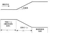
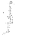
横延伸ゾーン長(L2)と予熱ゾーン長(L1)の比(L2/L1)が0.5〜30であることが好ましく、0.7〜20であることがより好ましく、1〜10であることがさらに好ましい(図1)。通常L2/L1は50以上で使用されることが多いが、本発明ではL2/L1を小さくしていることを特徴としている。即ちL1を長くし予熱時間を十分取ることでフィルム全面の温度むらを無くし均一な延伸を達成したものである。
横延伸ゾーンでの延伸倍率は1%〜200%が好ましく、10%〜150%がより好ましく、40%〜120%がさらに好ましい。
ここで、図1は、横延伸の予熱ゾーン長、延伸ゾーン長、拡幅角を示す図である。 また、拡幅角は図1に示すように拡幅(延伸)が開始する部分の角度を示す。さらに、後述するとおり、横延伸後に横延伸後熱処理ゾーンを設け熱処理することで、ボーイングを抑制することができる。
本発明における延伸倍率は以下式(1)で定義される。
式(1)
延伸倍率(%)=100×(延伸後の長さ−延伸前の長さ)/延伸前の長さ
このような延伸は、透明熱可塑性フィルムのガラス転移温度Tgとすると、Tg−10℃〜Tg+50℃で実施するのが好ましく、より好ましくはTg℃〜Tg+40℃であり、さらに好ましくはTg+5℃〜Tg+30℃である。
A retardation film made of a transparent thermoplastic resin having such characteristics can be achieved by the following stretching method. That is, it is a feature of the present invention that the following method is adopted in order to make the distribution of heat shrinkage rate and elastic modulus uniform, reduce the orientation angle, and perform more uniform stretching.
The ratio (L 2 / L 1 ) between the transverse stretching zone length (L 2 ) and the preheating zone length (L 1 ) is preferably 0.5-30, more preferably 0.7-20, and more preferably 1 Is more preferably 10 to 10 (FIG. 1). Usually, L 2 / L 1 is often used at 50 or more, but the present invention is characterized in that L 2 / L 1 is made small. That is, by extending L 1 and taking a sufficient preheating time, temperature unevenness on the entire surface of the film is eliminated and uniform stretching is achieved.
The stretch ratio in the transverse stretching zone is preferably 1% to 200%, more preferably 10% to 150%, and even more preferably 40% to 120%.
Here, FIG. 1 is a diagram showing a preheating zone length, a stretching zone length, and a widening angle of lateral stretching. Further, the widening angle indicates an angle of a portion where widening (stretching) starts as shown in FIG. Furthermore, as will be described later, bowing can be suppressed by providing a heat treatment zone after lateral stretching after the lateral stretching.
The draw ratio in the present invention is defined by the following formula (1).
Formula (1)
Stretch ratio (%) = 100 × (length after stretching−length before stretching) / length before stretching Such stretching is performed from Tg−10 ° C. to the glass transition temperature Tg of the transparent thermoplastic film. It is preferable to implement at Tg + 50 degreeC, More preferably, it is TgC-Tg + 40 degreeC, More preferably, it is Tg + 5 degreeC-Tg + 30 degreeC.
横延伸ゾーン内の拡幅角は、5度〜45度にすることが好ましく、10度〜40度にすることがより好ましく、15度〜35度にすることがさらに好ましい。延伸ゾーン内の拡幅角とは以下のように定義される。即ち横延伸はテンターレール上に設置したチャックでフィルム両端を把持し、このテンターレールの間隔を次第に拡幅することで行うが、このテンターレールの広がる角度を指す。
通常の延伸では拡幅角は60度以上の急激な角度で延伸するが、本発明では上記のような緩やかな角度で延伸することを特徴としている。これにより延伸むらが発生せず、均一な延伸を達成したことを特徴としている。
The widening angle in the transverse stretching zone is preferably 5 ° to 45 °, more preferably 10 ° to 40 °, and even more preferably 15 ° to 35 °. The widening angle in the stretching zone is defined as follows. That is, the lateral stretching is performed by gripping both ends of the film with a chuck installed on the tenter rail and gradually widening the interval between the tenter rails, and indicates the angle at which the tenter rail spreads.
In normal stretching, the widening angle is stretched at a steep angle of 60 degrees or more, but the present invention is characterized by stretching at a gentle angle as described above. As a result, there is no unevenness of stretching, and uniform stretching is achieved.
横延伸後に、横延伸温度T1−50℃〜T1−2℃で熱処理することが好ましい。ここで、T1は延伸温度である。横延伸後熱処理温度は、より好ましくはT1−40℃〜T1−4℃、さらに好ましくはT1−35℃〜T1−6℃にする。これにより配向角を小さくでき、本発明の範囲とすることができる。即ち配向角の変化は横延伸に伴うネックイン現象に起因し、チャック間中央部がチャック部(端部)より収縮しやすい。これは端部がチャックで固定され変形し難いのに対し中央部は変形し易いためである。この結果中央部の変形量が大きくなり、弓状に配向角が変化し(ボーイング現象)、端部の配向角が変化しやすい。このため、延伸後の配向角の変化を小さくするためには延伸後にネックインしないようにすれば良く、このため本発明のように延伸温度より下げてフィルムの弾性率を上げることで変形し難くしネックインの発生を抑制することが有効である。 After the transverse stretching, it is preferable to perform a heat treatment at a transverse stretching temperature T 1 -50 ° C to T 1 -2 ° C. Here, T 1 is the stretching temperature. The heat treatment temperature after transverse stretching is more preferably T 1 -40 ° C to T 1 -4 ° C, and further preferably T 1 -35 ° C to T 1 -6 ° C. Thereby, an orientation angle can be made small and it can be set as the scope of the present invention. That is, the change in the orientation angle is caused by a neck-in phenomenon accompanying lateral stretching, and the central part between chucks is more likely to contract than the chuck part (end part). This is because the end portion is fixed by a chuck and hardly deformed, whereas the central portion is easily deformed. As a result, the amount of deformation at the center increases, the orientation angle changes like a bow (Boeing phenomenon), and the orientation angle at the end tends to change. For this reason, in order to reduce the change in the orientation angle after stretching, it is only necessary not to neck-in after stretching. For this reason, it is difficult to deform by lowering the stretching temperature and increasing the elastic modulus of the film as in the present invention. It is effective to suppress the occurrence of neck-in.
横延伸前に、T1+2℃〜T1+50℃で熱処理することが好ましく、T1+4℃〜T1+45℃で熱処理することがより好ましく、T1+6℃〜T1+40℃で熱処理することがさらに好ましい。これにより配向角を小さくでき、本発明の範囲とすることができる。このような熱処理は前述の横延伸前の予熱ゾーンで実施することができる。
このように延伸前の温度を高くすることで、フィルムの弾性率を低下させ、延伸前(テンター入口側)に発生するネックインを発生し易くしている。これにより、延伸後にネックインを発生し難くさせる上記横延伸処理後の対策とバランスさせることでより配向角を小さくする効果を出すことができる。
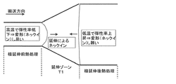
ここで、図2は、横延伸前熱処理、横延伸後熱処理により配向角を低減する機構を示す図である。具体的には、延伸ゾーンでは幅方向に延伸されるため、直交方向(搬送方向)にネックインが起こり細くなろうとする。このため延伸ゾーンの両側に搬送方向に弓状に変形しようとする力が働く。入口側(横延伸前熱処理温度)を高温にし、出口側(横延伸後熱処理)温度を低くすると、出口側より入口側が柔らかくなり変形し易くなる。この結果、入口側のみ弓状に変形し出口側の変形は抑制され、横延伸後の弓状の変形(ボーイング)を小さくでき、端部の配向角の変化の小さな(より均一な)フィルムを得ることができる。
Before transverse stretching, heat treatment is preferably performed at T 1 + 2 ° C. to T 1 + 50 ° C., more preferably heat treatment at T 1 + 4 ° C. to T 1 + 45 ° C., and heat treatment is performed at T 1 + 6 ° C. to T 1 + 40 ° C. More preferably. Thereby, an orientation angle can be made small and it can be set as the scope of the present invention. Such heat treatment can be carried out in the preheating zone before the transverse stretching described above.
By increasing the temperature before stretching in this way, the elastic modulus of the film is reduced, and neck-in that occurs before stretching (on the tenter inlet side) is likely to occur. Thereby, the effect which makes an orientation angle smaller can be taken out by balancing with the countermeasure after the said horizontal extending | stretching process which makes it difficult to generate | occur | produce a neck-in after extending | stretching.
Here, FIG. 2 is a diagram showing a mechanism for reducing the orientation angle by heat treatment before transverse stretching and heat treatment after transverse stretching. Specifically, since stretching is performed in the width direction in the stretching zone, neck-in occurs in the orthogonal direction (conveying direction) and tends to be thin. For this reason, the force which tries to deform | transform into the conveyance direction at both sides of an extending | stretching zone acts. When the inlet side (heat treatment temperature before transverse stretching) is set high and the outlet side (heat treatment after transverse stretching) temperature is lowered, the inlet side becomes softer than the outlet side and easily deforms. As a result, only the inlet side is deformed in an arcuate shape, the deformation on the outlet side is suppressed, the bow-shaped deformation (Boeing) after transverse stretching can be reduced, and a film with a small change in the orientation angle at the end (more uniform) Can be obtained.
縦/横比(L/W)が0.01越え0.3未満の範囲となるように縦延伸することが好ましい。より好ましくは0.05〜0.25であり、さらに好ましくは0.08〜0.2である。本発明の縦延伸は2対の以上にニップロールを用い入口側の周速より出口側の周速より速くすることで達成される。この時、延伸長(ニップロール間でフィルムがニップロールに接触していない部分の長さ)をLとし、延伸前のフィルムの幅をWとし、この比をL/Wとした。本発明ではL/Wを極端に小さくし短スパンで延伸するのが特徴であり(通常の縦延伸ではL/W0.5〜1.5で実施する)、これにより、均質な延伸を達成できる。L/W=0.5〜1.5ではネッキングが発生し易く、幅方向で延伸むらが発生し易くなるためである。これに対し本発明のように短スパンで延伸するとネッキングが発生し難く、幅方向の均一性が向上させることができる。
ここで、短スパン延伸法(斜め延伸法)はニップロール間を斜めにフィルムパスさせることにより、Lを短くでき縦横比の小さい縦延伸を実現し易くできる方法である。さらに縦延伸に引き続き縦緩和を行うことが好ましい。例えば、縦緩和は出口側ニップロールの搬送速度より、ニップロール後の搬送ロールの搬送速度を遅くすることで達成できる。
一方、通常の延伸法では、ニップロール間の隙間以上にLを小さくできないため、縦/横比を小さくし難い。
このような縦延伸の倍率は1%〜100%とすることが好ましく、より好ましくは2%〜50%、さらに好ましくは3%〜30%である。ここで言う延伸倍率は上述の式(1)で定義されるものである。
縦延伸温度はTg−20℃〜Tg+50℃で実施するのが好ましく、より好ましくはTg〜Tg+40℃、さらに好ましくはTg+5℃〜Tg+30℃である。
Longitudinal stretching is preferred so that the aspect ratio (L / W) is in the range of more than 0.01 and less than 0.3. More preferably, it is 0.05-0.25, More preferably, it is 0.08-0.2. The longitudinal stretching of the present invention is achieved by using two or more pairs of nip rolls so that the peripheral speed on the outlet side is higher than the peripheral speed on the outlet side. At this time, the stretching length (the length of the portion where the film is not in contact with the nip roll between the nip rolls) was L, the width of the film before stretching was W, and this ratio was L / W. In the present invention, L / W is extremely small and stretched with a short span (normal longitudinal stretching is performed at L / W of 0.5 to 1.5), and thus uniform stretching can be achieved. . This is because when L / W = 0.5 to 1.5, necking is likely to occur, and stretching unevenness is likely to occur in the width direction. On the other hand, when it is stretched with a short span as in the present invention, necking hardly occurs and the uniformity in the width direction can be improved.
Here, the short span stretching method (oblique stretching method) is a method in which L can be shortened and longitudinal stretching with a small aspect ratio can be easily realized by obliquely passing a film between nip rolls. Further, it is preferable to perform longitudinal relaxation subsequent to longitudinal stretching. For example, longitudinal relaxation can be achieved by making the conveyance speed of the conveyance roll after the nip roll slower than the conveyance speed of the exit side nip roll.
On the other hand, in the normal stretching method, L cannot be reduced more than the gap between the nip rolls, so it is difficult to reduce the aspect ratio.
The ratio of such longitudinal stretching is preferably 1% to 100%, more preferably 2% to 50%, and still more preferably 3% to 30%. The draw ratio here is defined by the above-mentioned formula (1).
The longitudinal stretching temperature is preferably Tg-20 ° C to Tg + 50 ° C, more preferably Tg to Tg + 40 ° C, still more preferably Tg + 5 ° C to Tg + 30 ° C.
ここで、長スパン延伸(通常の縦延伸)および短スパン延伸ついて詳細に説明する。
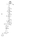
図3は、長スパン延伸を行う場合の、熱可塑性フィルムを溶融製膜で製造する場合のフィルム製造装置10の構成概略図である。
フィルム製造装置10は、液晶表示装置等に使用できる熱可塑性フィルムFを製造する装置である。熱可塑性フィルムFの原材料であるペレット状のセルロースアシレート樹脂またはシクロオレフィン樹脂を乾燥機12に導入して乾燥させた後、このペレットを押出機14によって押し出し、ギアポンプ16によりフィルタ18に供給する。次いで、フィルタ18により異物が濾過され、ダイ20から押し出される。その後、キャストドラム28とタッチロール24で挟まれ、キャストドラム28とロール26の間を通過して固化し、所定の表面粗さの未延伸フィルムFaが形成される。そして、この未延伸フィルムFaが長スパン延伸を行う縦延伸部30に供給される。
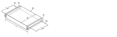
縦延伸部30では、未延伸フィルムFaが入口側ニップロール32及び出口側ニップローラ34間で搬送方向に延伸され、縦延伸フィルムFbとされる。なお、図4は、縦延伸部30の斜視説明図であり、縦延伸の縦/横比(L/W)は、入口側ニップロール32及び出口側ニップローラ34間の距離Lと、入口側ニップロール32及び出口側ニップローラ34の長さ方向の幅Wとによって規定される。次いで、縦延伸フィルムFbは、予熱部36を通過することで所定の予熱温度に調整された後、横延伸部42に供給される。
横延伸部42では、縦延伸フィルムFbが搬送方向と直交する幅方向に延伸され、横延伸フィルムFcとされる。そして、横延伸フィルムFcは、熱固定部44に供給され、巻取部46によって巻き取られることで、配向角、レターデーションが調整された最終製品である熱可塑性フィルムFが製造される。なお、横延伸フィルムFcには熱固定部44を通過した後、さらに熱緩和処理を施してもよい。
Here, the long span stretching (normal longitudinal stretching) and the short span stretching will be described in detail.
FIG. 3 is a schematic configuration diagram of the
The
In the
In the laterally stretched portion 42, the longitudinally stretched film Fb is stretched in the width direction orthogonal to the transport direction to form a laterally stretched film Fc. Then, the laterally stretched film Fc is supplied to the heat fixing unit 44 and wound up by the winding unit 46, whereby the thermoplastic film F which is the final product in which the orientation angle and retardation are adjusted is manufactured. Note that the transversely stretched film Fc may be further subjected to heat relaxation treatment after passing through the heat fixing portion 44.
一方、図5は、図3および図4に示す長スパン延伸を行う縦延伸部30に代えて、短スパン延伸を行う縦延伸部30aとしたフィルム製造装置10aの概略構成図である。
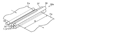
このフィルム製造装置10aでは、未延伸フィルムFaが予熱ロール33、35によって所定の温度まで予熱された後、二組のニップロール37、39間に供給されて縦延伸が行われる。この場合、ニップロール37、39は、未延伸フィルムFaの搬送方向に近接して配置されるとともに、上下方向に所定距離だけ高さが異なるように配置されている。ニップロール37、39をこのように配置することにより、縦延伸部30aにおける未延伸フィルムFaの搬送距離を確保できるとともに、縦延伸部30aの前後に配置される機構間の距離を短縮して、フィルム製造装置10aの小型化を図ることができる。
なお、図6は、縦延伸部30aの斜視説明図であり、縦延伸の縦/横比(L/W)は、ニップロール37、39によってニップされる未延伸フィルムFaの搬送方向の距離Lと、ニップロール37、39の長さ方向の幅Wとによって規定される。
On the other hand, FIG. 5 is a schematic configuration diagram of a
In this
6 is a perspective explanatory view of the longitudinally stretched
また、縦横比は2を超え50以下が好ましく、より好ましくは3〜40であり、さらに好ましくは4〜20であることも好ましい。
延伸に伴いフィルムは伸張されるが、この時フィルムは体積変化を小さくしようと厚み、および幅を減少させる。このときニップロールとフィルム間の摩擦により幅方向の収縮が制限される。このためニップロール間隔を大きくすると幅方向に収縮しやすくなり厚み減少を抑制できる。厚み減少が大きいとフィルムが厚み方向に圧縮されたことと同じ効果があり、フィルム面内に分子配向が進みRthが大きくなり易い。縦横比が大きく厚み減少が少ないと、逆にRthは発現し難く、低いRthを実現できる。
さらに縦横比が長いと幅方向の均一性を向上することができる。これは以下の理由による。
・縦延伸に伴いフィルムは幅方向に収縮しようとする。幅方向中央部では、その両側も幅方向に収縮しようとするため、綱引き状態となり自由に収縮できない。
・フィルム幅方向の端部は片側としか綱引き状態とならず、比較的自由に収縮できる。
・この両端と中央部の延伸に伴う収縮挙動の差が幅方向の延伸ムラとなる。
このような両端と中央部の不均一性により、幅方向のレターデーションむら、軸ズレ(遅相軸の配向角分布)が発生する。これに対し、長スパン延伸は長い2本のニップロール間でゆっくり延伸されるため、延伸中にこれらの不均一性の均一化(分子配向が均一になる)が進行する。これに対し、通常の縦延伸(縦横比=0.7〜2)では、このような均一化は発生しない。
The aspect ratio is preferably more than 2 and 50 or less, more preferably 3 to 40, and even more preferably 4 to 20.
The film is stretched as it is stretched. At this time, the film is reduced in thickness and width in order to reduce the volume change. At this time, shrinkage in the width direction is limited by friction between the nip roll and the film. For this reason, when the nip roll interval is increased, it is easy to contract in the width direction, and thickness reduction can be suppressed. When the thickness reduction is large, the same effect as that in which the film is compressed in the thickness direction is obtained, and molecular orientation advances in the film plane and Rth tends to increase. On the contrary, when the aspect ratio is large and the thickness reduction is small, Rth hardly appears and low Rth can be realized.
Furthermore, if the aspect ratio is long, the uniformity in the width direction can be improved. This is due to the following reason.
• The film tends to shrink in the width direction as it is stretched. At the central portion in the width direction, both sides thereof also try to contract in the width direction, so that it becomes a tug of war and cannot be contracted freely.
-The end in the film width direction is in a tug-of-war state only on one side and can be contracted relatively freely.
-The difference in shrinkage behavior associated with the stretching between both ends and the central portion becomes stretching unevenness in the width direction.
Due to such non-uniformity between both ends and the center, retardation in the width direction and axial deviation (orientation angle distribution of slow axis) occur. On the other hand, since long span stretching is performed slowly between two long nip rolls, the uniformity of these non-uniformities (the molecular orientation becomes uniform) proceeds during stretching. On the other hand, such normalization does not occur in normal longitudinal stretching (aspect ratio = 0.7-2).
延伸温度は、好ましくは(Tg-5℃)〜(Tg+100)℃、より好ましくは(Tg)〜(Tg+50)℃、さらに好ましくは(Tg+5)〜(Tg+30)℃である。延伸倍率は、好ましくは1.05〜3倍であり、より好ましくは1.05〜1.7倍であり、さらに好ましくは1.05〜1.4倍である。このような長スパン延伸は3対以上のニップロールで多段延伸しても良く、多段のうち最も長い縦横比が上記範囲に入っていればよい。
このような縦横比が2を越え50以下の延伸は、所定の距離だけ離れて設けられた2対のニップロールの間でフィルムを加熱して延伸すればよく、加熱方法はヒーター加熱法(赤外線ヒーター、ハロゲンヒーター、パネルヒーター等をフィルム上や下に設置し輻射熱で加熱)でもよく、ゾーン加熱法(熱風等を吹き込み所定の温度に調温したゾーン内で加熱)でもよい。本発明では延伸温度の均一性の観点からゾーン加熱法が好ましい。この時、ニップロールは延伸ゾーン内に設置しても良く、ゾーンの外に出しても良いが、フィルムとニップロールの粘着を防止するためにはゾーンの外に出すのが好ましい。このような延伸の前にフィルムを予熱することも好ましく、予熱温度は(Tg−80)℃〜(Tg+100)℃である。
The stretching temperature is preferably (Tg-5 ° C) to (Tg + 100) ° C, more preferably (Tg) to (Tg + 50) ° C, and still more preferably (Tg + 5) to (Tg + 30) ° C. The draw ratio is preferably 1.05 to 3 times, more preferably 1.05 to 1.7 times, and still more preferably 1.05 to 1.4 times. Such long span stretching may be performed in multiple stages with three or more pairs of nip rolls, and the longest aspect ratio of the multiple stages may be in the above range.
Such stretching with an aspect ratio exceeding 2 and not more than 50 may be performed by heating the film between two pairs of nip rolls provided at a predetermined distance, and the heating method is a heater heating method (infrared heater). In addition, a halogen heater, a panel heater or the like may be installed on or below the film and heated by radiant heat) or a zone heating method (heating in a zone in which hot air or the like is blown and adjusted to a predetermined temperature) may be used. In the present invention, the zone heating method is preferable from the viewpoint of uniformity of the stretching temperature. At this time, the nip roll may be installed in the stretching zone or out of the zone, but it is preferably out of the zone in order to prevent the film and the nip roll from sticking. It is also preferable to preheat the film before such stretching, and the preheating temperature is (Tg-80) ° C to (Tg + 100) ° C.
縦延伸後および横延伸後の少なくとも一方において、好ましくはTg−30℃〜Tg+30℃、より好ましくはTg−20℃〜Tg+20℃、さらに好ましくはTg−15℃〜Tg+15℃において、縦方向および横方向の緩和量の合計が1%〜20%、より好ましくは2%〜15%、さらに好ましくは3%〜12%となるように緩和することが好ましい。これにより、より延伸された部分が緩和されるため均一性をより向上できる。
縦方向の緩和(縦緩和)は、例えば、低張力(好ましくは20Kg/m以下、より好ましくは10kg/m以下)で搬送しながら上記温度で熱処理することで達成させることができる。緩和量は、フィルムの長手方向に一定間隔でつけた印が緩和後にどれだけ縮んだかで計測できる。縦緩和は縦延伸と横延伸の間、縦延伸および横延伸終了後等いずれの段階で実施しても良い。
横方向の緩和(横緩和)は延伸後にテンター幅を1%〜20%、より好ましくは2%〜15%狭めることで達成される。横緩和の温度は上記の範囲が好ましく、このような横緩和は、延伸後熱処理と併せて実施しても良く、延伸後熱処理の前で実施しても良く、延伸後熱処理の後で実施しても良い。
これらの縦方向の緩和(縦緩和)、横方向の緩和(横緩和)はどちらか一方だけでも効果があり、両方実施することも好ましい。
また、本発明で用いる熱可塑性フィルムの数平均重合度は15〜3000であり、より好ましくは30〜600である。熱可塑性樹脂がセルロースアシレート樹脂の場合の数平均重合度は、110〜270がより好ましく、より好ましくは120〜260であり、さらに好ましくは140〜250である。この範囲にすることで、延伸むらを抑制でき、熱収縮分布、弾性率分布を小さくすることができる。
In at least one of the longitudinal direction and the lateral direction, preferably at Tg-30 ° C to Tg + 30 ° C, more preferably at Tg-20 ° C to Tg + 20 ° C, more preferably at Tg-15 ° C to Tg + 15 ° C, in the longitudinal direction and the transverse direction. It is preferable to relax so that the total relaxation amount is 1% to 20%, more preferably 2% to 15%, and even more preferably 3% to 12%. Thereby, since the more extended | stretched part is relieve | moderated, uniformity can be improved more.
Longitudinal relaxation (longitudinal relaxation) can be achieved, for example, by performing heat treatment at the above temperature while transporting at low tension (preferably 20 kg / m or less, more preferably 10 kg / m or less). The amount of relaxation can be measured by how much the marks made at regular intervals in the longitudinal direction of the film shrink after relaxation. The longitudinal relaxation may be carried out at any stage such as between longitudinal stretching and transverse stretching, after completion of longitudinal stretching and transverse stretching.
Lateral relaxation (lateral relaxation) is achieved by narrowing the tenter width by 1% to 20%, more preferably 2% to 15% after stretching. The lateral relaxation temperature is preferably within the above range, and such lateral relaxation may be performed in combination with post-stretch heat treatment, may be performed before post-stretch heat treatment, or may be performed after post-stretch heat treatment. May be.
Any one of these longitudinal relaxations (longitudinal relaxation) and lateral relaxations (lateral relaxation) is effective, and it is also preferable to carry out both.
Moreover, the number average polymerization degree of the thermoplastic film used by this invention is 15-3000, More preferably, it is 30-600. When the thermoplastic resin is a cellulose acylate resin, the number average polymerization degree is more preferably 110 to 270, more preferably 120 to 260, and still more preferably 140 to 250. By setting it within this range, stretching unevenness can be suppressed, and heat shrinkage distribution and elastic modulus distribution can be reduced.
以下に、本発明の実施方法を手順にそって詳細に説明する。
本発明で用いる透明熱可塑性フィルムとしては、セルロースアシレート樹脂、ポリカーボネート樹脂、および、飽和ノルボルネン樹脂のいずれかを含む透明熱可塑性フィルムが好ましい。中でも好ましいのがセルロースアシレート樹脂および飽和ノルボルネン樹脂のいずれかを含む透明熱可塑性フィルムである。
Below, the implementation method of this invention is demonstrated in detail along a procedure.
As the transparent thermoplastic film used in the present invention, a transparent thermoplastic film containing any of a cellulose acylate resin, a polycarbonate resin, and a saturated norbornene resin is preferable. Among these, a transparent thermoplastic film containing any of cellulose acylate resin and saturated norbornene resin is preferable.
(セルロースアシレート樹脂)
本発明で用いるセルロースアシレートは以下の特徴を有するものが好ましい。(Aはアセテート基の置換度、Bはプロピオネート基、ブチレート基、ペンタノイル基の置換度の総和を示す)。
2.0≦A+B<3.0
0.1≦B<3
より好ましくは、Bの1/2以上がプロピオネート基の場合
2.6≦A+B≦2.95
2.0≦B≦2.95
Bの1/2未満がプロピオネート基の場合
2.6≦A+B≦2.95
1.3≦B≦2.5
さらに好ましくは、Bの1/2以上がプロピオネート基の場合
2.7≦A+B≦2.95
2.4≦B≦2.9
Bの1/2未満がプロピオネート基の場合
2.7≦A+B≦2.95
1.3≦B≦2.0
本発明では、アシル基の中に占めるアセテート基の置換度を少なくし、プロピオネート基、ブチレート基、ペンタノイル基の置換度の総和を多くしていることが特徴である。これにより、より延伸しやすくし、延伸に伴う不均一性(むら)をより軽減できる。これはアセテート基より長いこれらの基を多くすることでフィルムの柔軟性を向上させ延伸性を高めることができるためである。しかし、アシル基を上記のものより長くすると、ガラス転移温度や弾性率を低下させすぎる傾向にある。このためアセチル基より大きなプロピオネート基、ブチレート基、ペンタノイル基が好ましく、より好ましくはプロピオネート基、ブチレート基であり、さらに好ましくはプロピオネート基である。
また、本発明で用いるセルロースアシレートのTgとしては、100〜180℃が好ましく、120〜160℃がより好ましい。
(Cellulose acylate resin)
The cellulose acylate used in the present invention preferably has the following characteristics. (A represents the degree of substitution of the acetate group, and B represents the sum of the degree of substitution of the propionate group, butyrate group, and pentanoyl group).
2.0 ≦ A + B <3.0
0.1 ≦ B <3
More preferably, when ½ or more of B is a propionate group, 2.6 ≦ A + B ≦ 2.95
2.0 ≦ B ≦ 2.95
When less than 1/2 of B is a propionate group 2.6 ≦ A + B ≦ 2.95
1.3 ≦ B ≦ 2.5
More preferably, when ½ or more of B is a propionate group, 2.7 ≦ A + B ≦ 2.95
2.4 ≦ B ≦ 2.9
When less than 1/2 of B is a propionate group, 2.7 ≦ A + B ≦ 2.95
1.3 ≦ B ≦ 2.0
The present invention is characterized in that the substitution degree of the acetate group in the acyl group is reduced and the total substitution degree of the propionate group, butyrate group, and pentanoyl group is increased. Thereby, it becomes easier to extend | stretch and the nonuniformity (unevenness) accompanying extending | stretching can be reduced more. This is because increasing the number of these groups longer than the acetate group can improve the flexibility of the film and enhance the stretchability. However, if the acyl group is longer than the above, the glass transition temperature and elastic modulus tend to be lowered too much. For this reason, propionate groups, butyrate groups, and pentanoyl groups larger than acetyl groups are preferred, propionate groups and butyrate groups are more preferred, and propionate groups are more preferred.
Moreover, as Tg of the cellulose acylate used by this invention, 100-180 degreeC is preferable and 120-160 degreeC is more preferable.
本発明で用いることができるセルロースアシレートの製造方法の一例について詳細に説明する。本発明で用いることができるセルロースアシレートの、原料綿や合成方法については、発明協会公開技報(公技番号 2001−1745、2001年3月15日発行、発明協会)の7頁〜12頁にも詳細に記載されている。 An example of a method for producing cellulose acylate that can be used in the present invention will be described in detail. As for the raw material cotton and the synthesis method of cellulose acylate that can be used in the present invention, pages 7 to 12 of JIII Journal of Technical Disclosure (Technical No. 2001-1745, published on March 15, 2001, JIII). Are also described in detail.
(原料および前処理)
セルロース原料としては、広葉樹パルプ、針葉樹パルプ、綿花リンター由来のものが好ましく用いられる。セルロース原料としては、α−セルロース含量が92質量%〜99.9質量%の高純度のものを用いることが好ましい。
セルロース原料がフィルム状や塊状である場合は、あらかじめ解砕しておくことが好ましく、セルロースの形態はフラッフ状になるまで解砕が進行していることが好ましい。
(Raw material and pretreatment)
As the cellulose raw material, those derived from hardwood pulp, softwood pulp and cotton linter are preferably used. As a cellulose raw material, it is preferable to use a high-purity material having an α-cellulose content of 92 mass% to 99.9 mass%.
When the cellulose raw material is in the form of a film or a lump, it is preferable that the cellulose is pulverized in advance, and it is preferable that the pulverization proceeds until the cellulose is in a fluff form.
(活性化)
セルロース原料はアシル化に先立って、活性化剤と接触させる処理(活性化)を行うことが好ましい。活性化剤としては、カルボン酸または水を用いることができるが、水を用いた場合には、活性化の後に酸無水物を過剰に添加して脱水を行ったり、水を置換するためにカルボン酸で洗浄したり、アシル化の条件を調節したりするといった工程を含むことが好ましい。活性化剤はいかなる温度に調節して添加してもよく、添加方法としては噴霧、滴下、浸漬などの方法から選択することができる。
(activation)
Prior to acylation, the cellulose raw material is preferably subjected to a treatment (activation) for contact with an activator. As the activator, carboxylic acid or water can be used. However, when water is used, an excess of acid anhydride is added after activation to perform dehydration or to replace water. It is preferable to include a step of washing with an acid or adjusting acylation conditions. The activator may be added by adjusting to any temperature, and the addition method can be selected from spraying, dropping, dipping and the like.
活性化剤として好ましいカルボン酸は、炭素数2〜7のカルボン酸(例えば、酢酸、プロピオン酸、酪酸、2−メチルプロピオン酸、吉草酸、3−メチル酪酸、2−メチル酪酸、2,2−ジメチルプロピオン酸(ピバル酸)、ヘキサン酸、2−メチル吉草酸、3−メチル吉草酸、4−メチル吉草酸、2,2−ジメチル酪酸、2,3−ジメチル酪酸、3,3−ジメチル酪酸、シクロペンタンカルボン酸、ヘプタン酸、シクロヘキサンカルボン酸、安息香酸など)であり、より好ましくは、酢酸、プロピオン酸、または酪酸であり、特に好ましくは酢酸である。 Preferred carboxylic acids as activators are carboxylic acids having 2 to 7 carbon atoms (for example, acetic acid, propionic acid, butyric acid, 2-methylpropionic acid, valeric acid, 3-methylbutyric acid, 2-methylbutyric acid, 2,2- Dimethylpropionic acid (pivalic acid), hexanoic acid, 2-methylvaleric acid, 3-methylvaleric acid, 4-methylvaleric acid, 2,2-dimethylbutyric acid, 2,3-dimethylbutyric acid, 3,3-dimethylbutyric acid, Cyclopentanecarboxylic acid, heptanoic acid, cyclohexanecarboxylic acid, benzoic acid, etc.), more preferably acetic acid, propionic acid, or butyric acid, and particularly preferably acetic acid.
活性化の際は、必要に応じてさらに硫酸などのアシル化の触媒を加えることもできる。しかし、硫酸のような強酸を添加すると、解重合が促進されることがあるため、その添加量はセルロースに対して0.1質量%〜10質量%程度に留めることが好ましい。また、2種類以上の活性化剤を併用したり、炭素数2〜7のカルボン酸の酸無水物を添加したりしてもよい。 At the time of activation, an acylation catalyst such as sulfuric acid can be further added as necessary. However, when a strong acid such as sulfuric acid is added, depolymerization may be promoted. Therefore, the addition amount is preferably limited to about 0.1% by mass to 10% by mass with respect to cellulose. Two or more kinds of activators may be used in combination, or an acid anhydride of a carboxylic acid having 2 to 7 carbon atoms may be added.
活性化剤の添加量は、セルロースに対して5質量%以上であることが好ましく、10質量%以上であることがより好ましく、30質量%以上であることが特に好ましい。活性化剤の量が該下限値以上であれば、セルロースの活性化の程度が低下するなどの不具合が生じないので好ましい。活性化剤の添加量の上限は生産性を低下させない限りにおいて特に制限はないが、セルロースに対して質量で100倍以下であることが好ましく、20倍以下であることがより好ましく、10倍以下であることがさらに好ましい。活性化剤をセルロースに対して大過剰加えて活性化を行い、その後、ろ過、送風乾燥、加熱乾燥、減圧留去、溶媒置換などの操作を行って活性剤の量を減少させてもよい。 The addition amount of the activator is preferably 5% by mass or more, more preferably 10% by mass or more, and particularly preferably 30% by mass or more based on cellulose. It is preferable that the amount of the activator is equal to or more than the lower limit value because problems such as a decrease in the degree of activation of cellulose do not occur. The upper limit of the addition amount of the activator is not particularly limited as long as productivity is not lowered, but it is preferably 100 times or less, more preferably 20 times or less, and 10 times or less by mass with respect to cellulose. More preferably. Activation may be carried out by adding a large excess of activator to cellulose, and then the amount of the activator may be reduced by performing operations such as filtration, air drying, heat drying, distillation under reduced pressure, and solvent substitution.
活性化の時間は20分以上であることが好ましく、上限については生産性に影響を及ぼさない範囲であれば特に制限はないが、好ましくは72時間以下、さらに好ましくは24時間以下、特に好ましくは12時間以下である。また、活性化の温度は0℃〜90℃が好ましく、15℃〜80℃がさらに好ましく、20℃〜60℃が特に好ましい。セルロースの活性化の工程は加圧または減圧条件下で行うこともできる。また、加熱の手段として、マイクロ波や赤外線などの電磁波を用いてもよい。 The activation time is preferably 20 minutes or more, and the upper limit is not particularly limited as long as it does not affect productivity, but is preferably 72 hours or less, more preferably 24 hours or less, particularly preferably. 12 hours or less. The activation temperature is preferably 0 ° C to 90 ° C, more preferably 15 ° C to 80 ° C, and particularly preferably 20 ° C to 60 ° C. The step of activating cellulose can also be performed under pressure or reduced pressure. Moreover, you may use electromagnetic waves, such as a microwave and infrared rays, as a heating means.
(アシル化)
本発明におけるセルロースアシレートを製造する方法においては、セルロースにカルボン酸の酸無水物を加え、ブレンステッド酸またはルイス酸を触媒として反応させることで、セルロースの水酸基をアシル化することが好ましい。
セルロース混合アシレートを得る方法としては、アシル化剤として2種のカルボン酸無水物を混合または逐次添加により反応させる方法、2種のカルボン酸の混合酸無水物(例えば、酢酸・プロピオン酸混合酸無水物)を用いる方法、カルボン酸と別のカルボン酸の酸無水物(例えば、酢酸・プロピオン酸無水物)を原料として反応系内で混合酸無水物(例えば、酢酸・プロピオン酸混合酸無水物)を合成してセルロースと反応させる方法、置換度が3に満たないセルロースアシレートを一旦合成し、酸無水物や酸ハライドを用いて、残存する水酸基をさらにアシル化する方法などを用いることができる。
(Acylation)
In the method for producing cellulose acylate in the present invention, it is preferable to acylate the hydroxyl group of cellulose by adding an acid anhydride of carboxylic acid to cellulose and reacting with Bronsted acid or Lewis acid as a catalyst.
As a method for obtaining a cellulose mixed acylate, a method of reacting two carboxylic acid anhydrides as an acylating agent by mixing or sequentially adding them, a mixed acid anhydride of two carboxylic acids (for example, acetic acid / propionic acid mixed acid anhydride) A mixed acid anhydride (for example, acetic acid / propionic acid mixed acid anhydride) in a reaction system using a carboxylic acid and another carboxylic acid anhydride (for example, acetic acid / propionic acid anhydride) as a raw material. And a method in which cellulose acylate having a degree of substitution of less than 3 is synthesized once, and a remaining hydroxyl group is further acylated using an acid anhydride or an acid halide. .
(酸無水物)
カルボン酸の酸無水物として、好ましくはカルボン酸としての炭素数が2〜7であり、例えば、無水酢酸、プロピオン酸無水物、酪酸無水物、2−メチルプロピオン酸無水物、吉草酸無水物、3−メチル酪酸無水物、2−メチル酪酸無水物、2,2−ジメチルプロピオン酸無水物(ピバル酸無水物)、ヘキサン酸無水物、2−メチル吉草酸無水物、3−メチル吉草酸無水物、4−メチル吉草酸無水物、2,2−ジメチル酪酸無水物、2,3−ジメチル酪酸無水物、3,3−ジメチル酪酸無水物、シクロペンタンカルボン酸無水物、ヘプタン酸無水物、シクロヘキサンカルボン酸無水物、安息香酸無水物などを挙げることができる。
より好ましくは、無水酢酸、プロピオン酸無水物、酪酸無水物、吉草酸無水物、ヘキサン酸無水物、ヘプタン酸無水物などの無水物であり、より好ましくは、無水酢酸、プロピオン酸無水物、酪酸無水物である。
混合エステルを調製する目的で、これらの酸無水物を併用して使用することが好ましく行われる。その混合比は目的とする混合エステルの置換比に応じて決定することが好ましい。酸無水物は、セルロースに対して、通常は過剰当量添加する。すなわち、セルロースの水酸基に対して1.2〜50当量添加することが好ましく、1.5〜30当量添加することがより好ましく、2〜10当量添加することが特に好ましい。
(Acid anhydride)
The acid anhydride of the carboxylic acid preferably has 2 to 7 carbon atoms as the carboxylic acid. For example, acetic anhydride, propionic anhydride, butyric anhydride, 2-methylpropionic anhydride, valeric anhydride, 3-methylbutyric anhydride, 2-methylbutyric anhydride, 2,2-dimethylpropionic anhydride (pivalic anhydride), hexanoic anhydride, 2-methylvaleric anhydride, 3-methylvaleric anhydride 4-methylvaleric anhydride, 2,2-dimethylbutyric anhydride, 2,3-dimethylbutyric anhydride, 3,3-dimethylbutyric anhydride, cyclopentanecarboxylic anhydride, heptanoic anhydride, cyclohexanecarboxylic acid An acid anhydride, a benzoic acid anhydride, etc. can be mentioned.
More preferred are acetic anhydride, propionic anhydride, butyric anhydride, valeric anhydride, hexanoic anhydride, heptanoic anhydride and the like, and more preferred are acetic anhydride, propionic anhydride, butyric acid. Anhydrous.
For the purpose of preparing a mixed ester, it is preferable to use these acid anhydrides in combination. The mixing ratio is preferably determined according to the substitution ratio of the target mixed ester. The acid anhydride is usually added in excess equivalent to the cellulose. That is, it is preferable to add 1.2-50 equivalent with respect to the hydroxyl group of a cellulose, It is more preferable to add 1.5-30 equivalent, It is especially preferable to add 2-10 equivalent.
(触媒)
本発明におけるセルロースアシレートの製造に用いるアシル化の触媒には、ブレンステッド酸またはルイス酸を使用することが好ましい。ブレンステッド酸およびルイス酸の定義については、例えば、「理化学辞典」第五版(2000年)に記載されている。好ましいブレンステッド酸の例としては、硫酸、過塩素酸、リン酸、メタンスルホン酸、ベンゼンスルホン酸、p−トルエンスルホン酸などを挙げることができる。好ましいルイス酸の例としては、塩化亜鉛、塩化スズ、塩化アンチモン、塩化マグネシウムなどを挙げることができる。
触媒としては、硫酸または過塩素酸がより好ましく、硫酸が特に好ましい。触媒の好ましい添加量は、セルロースに対して0.1〜30質量%であり、より好ましくは1〜15質量%であり、特に好ましくは3〜12質量%である。
(catalyst)
It is preferable to use a Bronsted acid or a Lewis acid as the acylation catalyst used in the production of cellulose acylate in the present invention. The definitions of Bronsted acid and Lewis acid are described in, for example, “Physical and Chemical Dictionary”, 5th edition (2000). Examples of preferable Bronsted acid include sulfuric acid, perchloric acid, phosphoric acid, methanesulfonic acid, benzenesulfonic acid, p-toluenesulfonic acid and the like. Examples of preferred Lewis acids include zinc chloride, tin chloride, antimony chloride, magnesium chloride and the like.
As the catalyst, sulfuric acid or perchloric acid is more preferable, and sulfuric acid is particularly preferable. The preferable addition amount of a catalyst is 0.1-30 mass% with respect to a cellulose, More preferably, it is 1-15 mass%, Most preferably, it is 3-12 mass%.
(溶媒)
アシル化を行う際には、粘度、反応速度、攪拌性、アシル置換比などを調整する目的で、溶媒を添加してもよい。このような溶媒としては、ジクロロメタン、クロロホルム、カルボン酸、アセトン、エチルメチルケトン、トルエン、ジメチルスルホキシド、スルホランなどを用いることもできるが、好ましくはカルボン酸であり、例えば、炭素数2〜7のカルボン酸(例えば、酢酸、プロピオン酸、酪酸、2−メチルプロピオン酸、吉草酸、3−メチル酪酸、2−メチル酪酸、2,2−ジメチルプロピオン酸(ピバル酸)、ヘキサン酸、2−メチル吉草酸、3−メチル吉草酸、4−メチル吉草酸、2,2−ジメチル酪酸、2,3−ジメチル酪酸、3,3−ジメチル酪酸、シクロペンタンカルボン酸)などを挙げることができる。さらに好ましくは、酢酸、プロピオン酸、酪酸などを挙げることができる。これらの溶媒は混合して用いてもよい。
(solvent)
In carrying out acylation, a solvent may be added for the purpose of adjusting viscosity, reaction rate, stirring ability, acyl substitution ratio, and the like. As such a solvent, dichloromethane, chloroform, carboxylic acid, acetone, ethyl methyl ketone, toluene, dimethyl sulfoxide, sulfolane and the like can be used, but carboxylic acid is preferable, for example, a carboxylic acid having 2 to 7 carbon atoms. Acids (eg acetic acid, propionic acid, butyric acid, 2-methylpropionic acid, valeric acid, 3-methylbutyric acid, 2-methylbutyric acid, 2,2-dimethylpropionic acid (pivalic acid), hexanoic acid, 2-methylvaleric acid , 3-methylvaleric acid, 4-methylvaleric acid, 2,2-dimethylbutyric acid, 2,3-dimethylbutyric acid, 3,3-dimethylbutyric acid, cyclopentanecarboxylic acid). More preferably, acetic acid, propionic acid, butyric acid and the like can be mentioned. These solvents may be used as a mixture.
(アシル化の条件)
アシル化を行う際には、酸無水物と触媒、さらに、必要に応じて溶媒を混合してからセルロースと混合してもよく、またこれらを別々に逐次セルロースと混合してもよいが、通常は、酸無水物と触媒との混合物、または、酸無水物と触媒と溶媒との混合物をアシル化剤として調整してからセルロースと反応させることが好ましい。アシル化の際の反応熱による反応容器内の温度上昇を抑制するために、アシル化剤は予め冷却しておくことが好ましい。冷却温度としては、−50℃〜20℃が好ましく、−35℃〜10℃がより好ましく、−25℃〜5℃がさらに好ましい。アシル化剤は液状で添加しても、凍結させて結晶、フレーク、またはブロック状の固体として添加してもよい。
アシル化剤はさらに、セルロースに対して一度に添加しても、分割して添加してもよい。また、アシル化剤に対してセルロースを一度に添加しても、分割して添加してもよい。アシル化剤を分割して添加する場合は、同一組成のアシル化剤を用いても、複数の組成の異なるアシル化剤を用いても良い。好ましい例として、1)酸無水物と溶媒の混合物をまず添加し、次いで、触媒を添加する、2)酸無水物、溶媒と触媒の一部の混合物をまず添加し、次いで、触媒の残りと溶媒の混合物を添加する、3)酸無水物と溶媒の混合物をまず添加し、次いで、触媒と溶媒の混合物を添加する、4)溶媒をまず添加し、酸無水物と触媒との混合物あるいは酸無水物と触媒と溶媒との混合物を添加する、などを挙げることができる。
(Conditions for acylation)
When acylation is performed, an acid anhydride and a catalyst, and further, if necessary, a solvent may be mixed and then mixed with cellulose, or these may be separately mixed with cellulose. It is preferable to prepare a mixture of an acid anhydride and a catalyst or a mixture of an acid anhydride, a catalyst and a solvent as an acylating agent and then react with cellulose. In order to suppress an increase in temperature in the reaction vessel due to reaction heat during acylation, the acylating agent is preferably cooled in advance. The cooling temperature is preferably −50 ° C. to 20 ° C., more preferably −35 ° C. to 10 ° C., and further preferably −25 ° C. to 5 ° C. The acylating agent may be added in a liquid state or may be frozen and added as a crystal, flake or block solid.
Further, the acylating agent may be added to the cellulose at once or dividedly. In addition, cellulose may be added to the acylating agent all at once or in divided portions. When the acylating agent is added in portions, the same acylating agent or a plurality of different acylating agents may be used. As a preferred example, 1) a mixture of acid anhydride and solvent is added first, then the catalyst is added, and 2) a mixture of part of acid anhydride, solvent and catalyst is added first, then the rest of the catalyst and Add solvent mixture 3) Add acid anhydride and solvent mixture first, then add catalyst and solvent mixture 4) Add solvent first, acid anhydride and catalyst mixture or acid For example, a mixture of an anhydride, a catalyst, and a solvent may be added.
セルロースのアシル化は発熱反応であるが、本発明のセルロースアシレートを製造する方法においては、アシル化の際の最高到達温度が50℃以下であることが好ましい。反応温度がこの温度以下であれば、解重合が進行して本発明の用途に適した重合度のセルロースアシレートを得難くなるなどの不都合が生じないため好ましい。アシル化の際の最高到達温度は、好ましくは45℃以下であり、より好ましくは40℃以下であり、特に好ましくは35℃以下である。反応温度は温度調節装置を用いて制御しても、アシル化剤の初期温度で制御してもよい。反応容器を減圧して、反応系中の液体成分の気化熱で反応温度を制御することもできる。アシル化の際の発熱は反応初期が大きいため、反応初期には冷却し、その後は加熱するなどの制御を行うこともできる。アシル化の終点は、光線透過率、溶液粘度、反応系の温度変化、反応物の有機溶媒に対する溶解性、偏光顕微鏡観察などの手段により決定することができる。
反応の最低温度は−50℃以上が好ましく、−30℃以上がより好ましく、−20℃以上がさらに好ましい。好ましいアシル化時間は0.5時間〜24時間であり、1時間〜12時間がより好ましく、1.5時間〜6時間が特に好ましい。0.5時間以下では通常の反応条件では反応が十分に進行せず、24時間を越えると、工業的な製造のために好ましくない。
The acylation of cellulose is an exothermic reaction, but in the method for producing the cellulose acylate of the present invention, it is preferable that the maximum temperature reached during acylation is 50 ° C. or lower. If the reaction temperature is lower than this temperature, depolymerization proceeds and it is preferable because there is no inconvenience such as difficulty in obtaining a cellulose acylate having a polymerization degree suitable for the use of the present invention. The maximum temperature reached during acylation is preferably 45 ° C. or lower, more preferably 40 ° C. or lower, and particularly preferably 35 ° C. or lower. The reaction temperature may be controlled using a temperature control device or may be controlled by the initial temperature of the acylating agent. The reaction temperature can also be controlled by reducing the pressure of the reaction vessel and the heat of vaporization of the liquid component in the reaction system. Since the exotherm during the acylation is large in the initial stage of the reaction, it is possible to control such as cooling in the initial stage of the reaction and heating thereafter. The end point of acylation can be determined by means such as light transmittance, solution viscosity, temperature change of the reaction system, solubility of the reaction product in an organic solvent, and observation with a polarizing microscope.
The minimum temperature of the reaction is preferably −50 ° C. or higher, more preferably −30 ° C. or higher, and further preferably −20 ° C. or higher. A preferable acylation time is 0.5 to 24 hours, more preferably 1 to 12 hours, and particularly preferably 1.5 to 6 hours. If it is 0.5 hours or less, the reaction does not proceed sufficiently under normal reaction conditions, and if it exceeds 24 hours, it is not preferred for industrial production.
(反応停止剤)
本発明に用いられるセルロースアシレートを製造する方法においては、アシル化反応の後に、反応停止剤を加えることが好ましい。
反応停止剤としては、酸無水物を分解するものであればいかなるものでもよく、好ましい例として、水、アルコール(例えば、エタノール、メタノール、プロパノール、イソプロピルアルコールなど)またはこれらを含有する組成物などを挙げることができる。また、反応停止剤には、後述の中和剤を含んでいても良い。反応停止剤の添加に際しては、反応装置の冷却能力を超える大きな発熱が生じて、セルロースアシレートの重合度を低下させる原因となったり、セルロースアシレートが望まない形態で沈殿したりする場合があるなどの不都合を避けるため、水やアルコールを直接添加するよりも、酢酸、プロピオン酸、酪酸等のカルボン酸と水との混合物を添加することが好ましく、カルボン酸としては酢酸が特に好ましい。カルボン酸と水の組成比は任意の割合で用いることができるが、水の含有量が5質量%〜80質量%、さらには10質量%〜60質量%、特には15質量%〜50質量%の範囲であることが好ましい。
反応停止剤は、アシル化の反応容器に添加しても、反応停止剤の容器に反応物を添加してもよい。反応停止剤は3分〜3時間かけて添加することが好ましい。反応停止剤の添加時間が3分以上であれば、発熱が大きくなりすぎて重合度低下の原因となったり、酸無水物の加水分解が不十分になったり、セルロースアシレートの安定性を低下させたりするなどの不都合が生じないので好ましい。また反応停止剤の添加時間が3時間以下であれば、工業的な生産性の低下などの問題も生じないので好ましい。反応停止剤の添加時間として、好ましくは4分〜2時間であり、より好ましくは5分〜1時間であり、特に好ましくは10分〜45分である。反応停止剤を添加する際には反応容器を冷却しても冷却しなくてもよいが、解重合を抑制する目的から、反応容器を冷却して温度上昇を抑制することが好ましい。また、反応停止剤を冷却しておくことも好ましい。
(Reaction terminator)
In the method for producing cellulose acylate used in the present invention, it is preferable to add a reaction terminator after the acylation reaction.
The reaction terminator may be any as long as it decomposes the acid anhydride, and preferable examples include water, alcohol (eg, ethanol, methanol, propanol, isopropyl alcohol, etc.) or a composition containing these. Can be mentioned. Moreover, the reaction terminator may contain a neutralizing agent described later. Upon addition of the reaction terminator, a large exotherm exceeding the cooling capacity of the reaction apparatus may occur, which may cause a decrease in the degree of polymerization of the cellulose acylate or may precipitate the cellulose acylate in an undesired form. In order to avoid such inconveniences, it is preferable to add a mixture of carboxylic acid such as acetic acid, propionic acid, butyric acid and water rather than directly adding water or alcohol, and acetic acid is particularly preferable as the carboxylic acid. The composition ratio of carboxylic acid and water can be used at any ratio, but the water content is 5% by mass to 80% by mass, further 10% by mass to 60% by mass, and particularly 15% by mass to 50% by mass. It is preferable that it is the range of these.
The reaction terminator may be added to the acylation reaction vessel or the reactant may be added to the reaction terminator vessel. The reaction terminator is preferably added over 3 minutes to 3 hours. If the addition time of the reaction terminator is 3 minutes or more, the exotherm becomes too large, causing a decrease in the degree of polymerization, insufficient hydrolysis of the acid anhydride, and reducing the stability of cellulose acylate. This is preferable because there is no inconvenience. Moreover, it is preferable that the addition time of the reaction terminator is 3 hours or less because problems such as industrial productivity decrease do not occur. The addition time of the reaction terminator is preferably 4 minutes to 2 hours, more preferably 5 minutes to 1 hour, and particularly preferably 10 minutes to 45 minutes. When adding the reaction terminator, the reaction vessel may or may not be cooled, but for the purpose of suppressing depolymerization, it is preferable to cool the reaction vessel to suppress the temperature rise. It is also preferable to cool the reaction terminator.
(中和剤)
アシル化の反応停止工程あるいはアシル化の反応停止工程後に、系内に残存している過剰の無水カルボン酸の加水分解、カルボン酸およびエステル化触媒の一部または全部の中和のために、中和剤(例えば、カルシウム、マグネシウム、鉄、アルミニウムまたは亜鉛の炭酸塩、酢酸塩、水酸化物または酸化物)またはその溶液を添加してもよい。中和剤の溶媒としては、水、アルコール(例えば、エタノール、メタノール、プロパノール、イソプロピルアルコールなど)、カルボン酸(例えば、酢酸、プロピオン酸、酪酸など)、ケトン(例えば、アセトン、エチルメチルケトンなど)、ジメチルスルホキシドなどの極性溶媒、およびこれらの混合溶媒を好ましい例として挙げることができる。
(Neutralizer)
In order to hydrolyze excess carboxylic anhydride remaining in the system after the acylation stop step or the acylation stop step, and to neutralize some or all of the carboxylic acid and the esterification catalyst, Additives (eg, calcium, magnesium, iron, aluminum or zinc carbonates, acetates, hydroxides or oxides) or solutions thereof may be added. As a solvent for the neutralizing agent, water, alcohol (eg, ethanol, methanol, propanol, isopropyl alcohol, etc.), carboxylic acid (eg, acetic acid, propionic acid, butyric acid, etc.), ketone (eg, acetone, ethyl methyl ketone, etc.) Preferred examples include polar solvents such as dimethyl sulfoxide, and mixed solvents thereof.
(部分加水分解)
このようにして得られたセルロースアシレートは、全置換度がほぼ3に近いものであるが、所望の置換度のものを得る目的で、少量の触媒(一般には、残存する硫酸などのアシル化触媒)と水との存在下で、20〜90℃に数分〜数日間保つことによりエステル結合を部分的に加水分解し、セルロースアシレートのアシル置換度を所望の程度まで減少させること(いわゆる熟成)が一般的に行われる。部分加水分解の過程でセルロースの硫酸エステルも加水分解されることから、加水分解の条件を調節することにより、セルロースに結合した硫酸エステルの量を削減することができる。
所望のセルロースアシレートが得られた時点で、系内に残存している触媒を、前記のような中和剤またはその溶液を用いて完全に中和し、部分加水分解を停止させることが好ましい。反応溶液に対して溶解性が低い塩を生成する中和剤(例えば、炭酸マグネシウム、酢酸マグネシウムなど)を添加することにより、溶液中あるいはセルロースに結合した触媒(例えば、硫酸エステル)を効果的に除去することも好ましい。
(Partial hydrolysis)
The cellulose acylate thus obtained has a total degree of substitution close to 3. However, for the purpose of obtaining a desired degree of substitution, a small amount of catalyst (generally, acylation of remaining sulfuric acid or the like) is performed. (Catalyst) and water in the presence of 20 to 90 ° C. for several minutes to several days to partially hydrolyze the ester bond and reduce the acyl substitution degree of cellulose acylate to a desired level (so-called Aging) is generally performed. Since the cellulose sulfate ester is also hydrolyzed during the partial hydrolysis, the amount of sulfate ester bound to the cellulose can be reduced by adjusting the hydrolysis conditions.
When the desired cellulose acylate is obtained, it is preferable to completely neutralize the catalyst remaining in the system using the neutralizing agent as described above or a solution thereof to stop partial hydrolysis. . By adding a neutralizing agent (for example, magnesium carbonate, magnesium acetate, etc.) that generates a salt that is poorly soluble in the reaction solution, a catalyst (for example, sulfate ester) bound to the solution or to cellulose is effectively removed. It is also preferable to remove.
(ろ過)
セルロースアシレート中の未反応物、難溶解性塩、その他の異物などを除去または削減する目的として、反応混合物(ドープ)のろ過を行うことが好ましい。ろ過は、アシル化の完了から再沈殿までの間のいかなる工程において行ってもよい。ろ過圧や取り扱い性の制御の目的から、ろ過に先立って適切な溶媒で希釈することも好ましい。
(Filtration)
The reaction mixture (dope) is preferably filtered for the purpose of removing or reducing unreacted substances, hardly soluble salts, and other foreign matters in the cellulose acylate. Filtration may be performed at any step between the completion of acylation and reprecipitation. For the purpose of controlling filtration pressure and handleability, it is also preferable to dilute with an appropriate solvent prior to filtration.
(再沈殿)
このようにして得られたセルロースアシレート溶液を、水もしくはカルボン酸(例えば、酢酸、プロピオン酸など)水溶液のような貧溶媒中に混合するか、セルロースアシレート溶液中に、貧溶媒を混合することにより、セルロースアシレートを再沈殿させ、洗浄および安定化処理により目的のセルロースアシレートを得ることができる。再沈殿は連続的に行っても、一定量ずつバッチ式で行ってもよい。セルロースアシレート溶液の濃度および貧溶媒の組成をセルロースアシレートの置換様式あるいは重合度により調整することで、再沈殿したセルロースアシレートの形態や分子量分布を制御することも好ましい。
(Reprecipitation)
The cellulose acylate solution thus obtained is mixed in a poor solvent such as water or an aqueous solution of carboxylic acid (for example, acetic acid, propionic acid, etc.), or the poor solvent is mixed in the cellulose acylate solution. As a result, the cellulose acylate can be re-precipitated and the desired cellulose acylate can be obtained by washing and stabilizing treatment. Reprecipitation may be carried out continuously or batchwise by a fixed amount. It is also preferable to control the form and molecular weight distribution of the re-precipitated cellulose acylate by adjusting the concentration of the cellulose acylate solution and the composition of the poor solvent according to the substitution mode of the cellulose acylate or the degree of polymerization.
(洗浄)
生成したセルロースアシレートは洗浄処理することが好ましい。洗浄溶媒はセルロースアシレートの溶解性が低く、かつ、不純物を除去することができるものであればいかなるものでも良いが、通常は水または温水が用いられる。洗浄水の温度は、好ましくは25℃〜100℃であり、さらに好ましくは30℃〜90℃であり、特に好ましくは40℃〜80℃である。洗浄処理はろ過と洗浄液の交換を繰り返すいわゆるバッチ式で行っても、連続洗浄装置を用いて行ってもよい。再沈殿および洗浄の工程で発生した廃液を再沈殿工程の貧溶媒として再利用したり、蒸留などの手段によりカルボン酸などの溶媒を回収して再利用することも好ましい。
洗浄の進行はいかなる手段で追跡を行ってよいが、水素イオン濃度、イオンクロマトグラフィー、電気伝導度、ICP、元素分析、原子吸光スペクトルなどの方法を好ましい例として挙げることができる。
このような処理により、セルロースアシレート中の触媒(硫酸、過塩素酸、トリフルオロ酢酸、p−トルエンスルホン酸、メタンスルホン酸、塩化亜鉛など)、中和剤(例えば、カルシウム、マグネシウム、鉄、アルミニウムまたは亜鉛の炭酸塩、酢酸塩、水酸化物または酸化物など)、中和剤と触媒との反応物、カルボン酸(酢酸、プロピオン酸、酪酸など)、中和剤とカルボン酸との反応物などを除去することができ、このことはセルロースアシレートの安定性を高めるために有効である。
(Washing)
The produced cellulose acylate is preferably washed. Any washing solvent may be used as long as it has low solubility of cellulose acylate and can remove impurities, but water or warm water is usually used. The temperature of the washing water is preferably 25 ° C to 100 ° C, more preferably 30 ° C to 90 ° C, and particularly preferably 40 ° C to 80 ° C. The washing treatment may be performed by a so-called batch method in which filtration and replacement of the washing liquid are repeated, or may be carried out using a continuous washing apparatus. It is also preferable to reuse the waste liquid generated in the reprecipitation and washing steps as a poor solvent in the reprecipitation step, or to recover and reuse a solvent such as carboxylic acid by means such as distillation.
The progress of washing may be traced by any means, but preferred examples include methods such as hydrogen ion concentration, ion chromatography, electrical conductivity, ICP, elemental analysis, and atomic absorption spectrum.
By such treatment, the catalyst (sulfuric acid, perchloric acid, trifluoroacetic acid, p-toluenesulfonic acid, methanesulfonic acid, zinc chloride, etc.) in the cellulose acylate, neutralizing agent (for example, calcium, magnesium, iron, Aluminum or zinc carbonates, acetates, hydroxides or oxides), reaction products of neutralizing agents and catalysts, carboxylic acids (eg acetic acid, propionic acid, butyric acid), reactions of neutralizing agents with carboxylic acids Can be removed, which is effective to increase the stability of cellulose acylate.
(安定化)
温水処理による洗浄後のセルロースアシレートは、安定性をさらに向上させたり、カルボン酸臭を低下させるために、弱アルカリ(例えば、ナトリウム、カリウム、カルシウム、マグネシウム、アルミニウムなどの炭酸塩、炭酸水素塩、水酸化物、酸化物など)の水溶液などで処理することも好ましい。
残存不純物の量は、洗浄液の量、洗浄の温度、時間、攪拌方法、洗浄容器の形態、安定化剤の組成や濃度により制御できる。本発明においては、残留硫酸根量(硫黄原子の含有量として)が0〜500ppmになるようにアシル化、部分加水分解および洗浄の条件を設定する。
(Stabilization)
Cellulose acylate after washing with hot water treatment is weakly alkaline (for example, carbonates, bicarbonates such as sodium, potassium, calcium, magnesium, aluminum, etc.) in order to further improve the stability or reduce the carboxylic acid odor. It is also preferable to treat with an aqueous solution of hydroxide, oxide, etc.).
The amount of residual impurities can be controlled by the amount of cleaning liquid, cleaning temperature, time, stirring method, shape of cleaning container, composition and concentration of stabilizer. In the present invention, conditions for acylation, partial hydrolysis and washing are set so that the amount of residual sulfate radical (as the sulfur atom content) is 0 to 500 ppm.
(乾燥)
本発明においてセルロースアシレートの含水率を好ましい量に調整するためには、セルロースアシレートを乾燥することが好ましい。乾燥の方法については、目的とする含水率が得られるのであれば特に限定されないが、加熱、送風、減圧、攪拌などの手段を単独または組み合わせで用いることで効率的に行うことが好ましい。乾燥温度として好ましくは0〜200℃であり、さらに好ましくは40〜180℃であり、特に好ましくは50〜160℃である。本発明のセルロースアシレートは、その含水率が2質量%以下であることが好ましく、1質量%以下であることがさらに好ましく、0.7質量%以下であることが特に好ましい。
(Dry)
In the present invention, in order to adjust the water content of the cellulose acylate to a preferable amount, it is preferable to dry the cellulose acylate. The drying method is not particularly limited as long as the desired moisture content can be obtained. However, it is preferable that the drying method be performed efficiently by using means such as heating, air blowing, decompression, and stirring alone or in combination. The drying temperature is preferably 0 to 200 ° C, more preferably 40 to 180 ° C, and particularly preferably 50 to 160 ° C. The cellulose acylate of the present invention has a water content of preferably 2% by mass or less, more preferably 1% by mass or less, and particularly preferably 0.7% by mass or less.
(形態)
本発明のセルロースアシレートは粒子状、粉末状、繊維状、塊状など種々の形状を取ることができるが、フィルム製造の原料としては粒子状または粉末状であることが好ましいことから、乾燥後のセルロースアシレートは、粒子サイズの均一化や取り扱い性の改善のために、粉砕や篩がけを行っても良い。セルロースアシレートが粒子状であるとき、使用する粒子の90質量%以上は、0.5〜5mmの粒子サイズを有することが好ましい。また、使用する粒子の50質量%以上が1〜4mmの粒子サイズを有することが好ましい。セルロースアシレート粒子は、なるべく球形に近い形状を有することが好ましい。また、本発明のセルロースアシレート粒子は、見かけ密度が好ましくは0.5〜1.3、さらに好ましくは0.7〜1.2、特に好ましくは0.8〜1.15である。見かけ密度の測定法に関しては、JIS K−7365に規定されている。
本発明のセルロースアシレート粒子は安息角が10〜70度であることが好ましく、15〜60度であることがさらに好ましく、20〜50度であることが特に好ましい。
(Form)
The cellulose acylate of the present invention can take various shapes such as particles, powders, fibers and lumps, but it is preferable that the raw materials for film production are particles or powders. Cellulose acylate may be pulverized or sieved to make the particle size uniform and improve handling. When the cellulose acylate is in the form of particles, 90% by mass or more of the particles used preferably have a particle size of 0.5 to 5 mm. Moreover, it is preferable that 50 mass% or more of the particle | grains to be used have a particle size of 1-4 mm. The cellulose acylate particles preferably have a shape as close to a sphere as possible. In addition, the cellulose acylate particles of the present invention preferably have an apparent density of 0.5 to 1.3, more preferably 0.7 to 1.2, and particularly preferably 0.8 to 1.15. The method for measuring the apparent density is defined in JIS K-7365.
The cellulose acylate particles of the present invention preferably have an angle of repose of 10 to 70 degrees, more preferably 15 to 60 degrees, and particularly preferably 20 to 50 degrees.
(重合度)
本発明で好ましく用いられるセルロースアシレートの数平均重合度は110〜270であり、好ましくは120〜260であり、さらに好ましくは140〜250である。数平均重合度は、本発明では後述のゲル浸透クロマトグラフィー (GPC)を用いた方法で測定される。
本発明においては、セルロースアシレートのGPCによる重量平均重合度/数平均重合度が1.6〜3.6であることが好ましく、1.7〜3.3であることがさらに好ましく、1.8〜3.2であることがさらに好ましい。
これらのセルロースアシレートは1種類のみを用いてもよく、2種以上混合しても良い。また、セルロースアシレート以外の高分子成分を適宜混合したものでもよい。混合される高分子成分はセルロースエステルと相溶性に優れるものが好ましく、フィルムにしたときの透過率が80%以上、さらに好ましくは90%以上、さらに好ましくは92%以上である。
(Degree of polymerization)
The number average degree of polymerization of the cellulose acylate preferably used in the present invention is 110 to 270, preferably 120 to 260, and more preferably 140 to 250. In the present invention, the number average degree of polymerization is measured by a method using gel permeation chromatography (GPC) described later.
In the present invention, the weight average degree of polymerization / number average degree of polymerization of cellulose acylate by GPC is preferably 1.6 to 3.6, more preferably 1.7 to 3.3. More preferably, it is 8-3.2.
These cellulose acylates may be used alone or in combination of two or more. Further, a polymer component other than cellulose acylate may be appropriately mixed. The polymer component to be mixed is preferably one having excellent compatibility with the cellulose ester, and the transmittance when formed into a film is 80% or more, more preferably 90% or more, and further preferably 92% or more.
(芳香族アシル化セルロースアシレート)
本発明では、下記式(T−1)および(T−2)を満たす組成を有する芳香族アシル化セルロースアシレートを用いることも好ましい。
式(T−1):2.5≦A+C<3.0
式(T−2):0.1≦C<2
より好ましくは、
式(T−3):2.6≦A+C<2.95
式(T−4):0.1≦C<1.5
さらに好ましくは、
式(T−3):2.7≦A+C<2.95
式(T−4):0.1≦C<1.0
である。
尚、式中Aは、アセチル基の置換度を示し、Cは置換もしくは無置換の芳香族アシル基を示す。 ここで置換もしくは無置換の芳香族アシル基としては下記一般式(I)で表される基があげられる。
(Aromatic acylated cellulose acylate)
In the present invention, it is also preferable to use an aromatic acylated cellulose acylate having a composition satisfying the following formulas (T-1) and (T-2).
Formula (T-1): 2.5 <= A + C <3.0
Formula (T-2): 0.1 ≦ C <2
More preferably,
Formula (T-3): 2.6 <= A + C <2.95
Formula (T-4): 0.1 ≦ C <1.5
More preferably,
Formula (T-3): 2.7 <= A + C <2.95
Formula (T-4): 0.1 ≦ C <1.0
It is.
In the formula, A represents the degree of substitution of the acetyl group, and C represents a substituted or unsubstituted aromatic acyl group. Here, examples of the substituted or unsubstituted aromatic acyl group include groups represented by the following general formula (I).
まず、一般式(I)について説明する。Xは置換基で、置換基の例には、ハロゲン原子、シアノ基、アルキル基、アルコキシ基、アリール基、アリールオキシ基、アシル基、カルボンアミド基、スルホンアミド基、ウレイド基、アラルキル基、ニトロ基、アルコキシカルボニル基、アリールオキシカルボニル基、アラルキルオキシカルボニル基、カルバモイル基、スルファモイル基、アシルオキシ基、アルケニル基、アルキニル基、アルキルスルホニル基、アリールスルホニル基、アルキルオキシスルホニル基、アリールオキシスルホニル基、アルキルスルホニルオキシ基およびアリールオキシスルホニル基、−S−R、−NH−CO−OR、−PH−R、−P(−R)2、−PH−O−R、−P(−R)(−O−R)、−P(−O−R)2、−PH(=O)−R−P(=O)(−R)2、−PH(=O)−O−R、−P(=O)(−R)(−O−R)、−P(=O)(−O−R)2、−O−PH(=O)−R、−O−P(=O)(−R)2−O−PH(=O)−O−R、−O−P(=O)(−R)(−O−R)、−O−P(=O)(−O−R)2、−NH−PH(=O)−R、−NH−P(=O)(−R)(−O−R)、−NH−P(=O)(−O−R)2、−SiH2−R、−SiH(−R)2、−Si(−R)3、−O−SiH2−R、−O−SiH(−R)2および−O−Si(−R)3が含まれる。上記Rは脂肪族基、芳香族基またはヘテロ環基である。置換基の数は、1〜5個であることが好ましく、1〜4個であることがより好ましく、1〜3個であることがさらに好ましく、1または2個であることが最も好ましい。置換基としては、ハロゲン原子、シアノ基、アルキル基、アルコキシ基、アリール基、アリールオキシ基、アシル基、カルボンアミド基、スルホンアミド基およびウレイド基が好ましく、ハロゲン原子、シアノ基、アルキル基、アルコキシ基、アリールオキシ基、アシル基およびカルボンアミド基がより好ましく、ハロゲン原子、シアノ基、アルキル基、アルコキシ基およびアリールオキシ基がさらに好ましく、ハロゲン原子、アルキル基およびアルコキシ基が最も好ましい。 First, general formula (I) will be described. X is a substituent. Examples of the substituent include a halogen atom, a cyano group, an alkyl group, an alkoxy group, an aryl group, an aryloxy group, an acyl group, a carbonamido group, a sulfonamido group, a ureido group, an aralkyl group, and a nitro group. Group, alkoxycarbonyl group, aryloxycarbonyl group, aralkyloxycarbonyl group, carbamoyl group, sulfamoyl group, acyloxy group, alkenyl group, alkynyl group, alkylsulfonyl group, arylsulfonyl group, alkyloxysulfonyl group, aryloxysulfonyl group, alkyl Sulfonyloxy and aryloxysulfonyl groups, —S—R, —NH—CO—OR, —PH—R, —P (—R) 2 , —PH—O—R, —P (—R) (— O -R), -P (-O-R) 2 , -PH (= O) -RP (= O) (-R) 2 , -PH (= O) -O-R, -P (= O) (-R) (-O-R), -P (= O) (-O-R) 2 , -O-PH (= O) -R, -O- P (═O) (— R) 2 —O—PH (═O) —O—R, —O—P (═O) (— R) (— O—R), —O—P (═O) (—O—R) 2 , —NH—PH (═O) —R, —NH—P (═O) (— R) (— O—R), —NH—P (═O) (— O— R) 2, -SiH 2 -R, -SiH (-R) 2, -Si (-R) 3, -O-SiH 2 -R, -O-SiH (-R) 2 and -O-Si (- R) 3 is included. R is an aliphatic group, an aromatic group or a heterocyclic group. The number of substituents is preferably 1 to 5, more preferably 1 to 4, further preferably 1 to 3, and most preferably 1 or 2. As the substituent, a halogen atom, a cyano group, an alkyl group, an alkoxy group, an aryl group, an aryloxy group, an acyl group, a carbonamido group, a sulfonamide group, and a ureido group are preferable, and a halogen atom, a cyano group, an alkyl group, an alkoxy group Group, aryloxy group, acyl group and carbonamido group are more preferred, halogen atom, cyano group, alkyl group, alkoxy group and aryloxy group are more preferred, and halogen atom, alkyl group and alkoxy group are most preferred.
上記ハロゲン原子には、フッ素原子、塩素原子、臭素原子およびヨウ素原子が含まれる。
上記アルキル基は、環状構造または分岐構造を有していてもよい。アルキル基の炭素原子数は、1〜20であることが好ましく、1〜12であることがより好ましく、1〜6であることがさらに好ましく、1〜4であることが最も好ましい。アルキル基が置換基を有する場合は、該置換基の炭素原子数も含めた数が、前記炭素原子数であることが好ましい(以下、他の基についても同じ)。アルキル基の例には、メチル基、エチル基、プロピル基、イソプロピル基、ブチル基、tert−ブチル基、ヘキシル基、シクロヘキシル基、オクチル基および2−エチルヘキシル基が含まれる。
上記アルコキシ基は、環状構造または分岐を有していてもよい。アルコキシ基の炭素原子数は、1〜20であることが好ましく、1〜12であることがより好ましく、1〜6であることがさらに好ましく、1〜4であることが最も好ましい。アルコキシ基は、さらに別のアルコキシ基で置換されていてもよい。アルコキシ基の例には、メトキシ基、エトキシ基、2−メトキシエトキシ基、2−メトキシ−2−エトキシエトキシ基、ブチルオキシ基、ヘキシルオキシ基およびオクチルオキシ基が含まれる。
The halogen atom includes a fluorine atom, a chlorine atom, a bromine atom and an iodine atom.
The alkyl group may have a cyclic structure or a branched structure. The number of carbon atoms in the alkyl group is preferably 1-20, more preferably 1-12, still more preferably 1-6, and most preferably 1-4. When the alkyl group has a substituent, the number including the number of carbon atoms of the substituent is preferably the number of carbon atoms (hereinafter, the same applies to other groups). Examples of the alkyl group include methyl group, ethyl group, propyl group, isopropyl group, butyl group, tert-butyl group, hexyl group, cyclohexyl group, octyl group and 2-ethylhexyl group.
The alkoxy group may have a cyclic structure or a branch. The number of carbon atoms in the alkoxy group is preferably 1-20, more preferably 1-12, still more preferably 1-6, and most preferably 1-4. The alkoxy group may be further substituted with another alkoxy group. Examples of the alkoxy group include methoxy group, ethoxy group, 2-methoxyethoxy group, 2-methoxy-2-ethoxyethoxy group, butyloxy group, hexyloxy group and octyloxy group.
上記アリール基の炭素原子数は、6〜20であることが好ましく、6〜12であることがより好ましい。アリール基の例には、フェニル基およびナフチル基が含まれる。上記アリールオキシ基の炭素原子数は、6〜20であることが好ましく、6〜12であることがさらに好ましい。
上記アリールオキシ基の例には、フェノキシ基およびナフトキシ基が含まれる。上記アシル基の炭素原子数は、1〜20であることが好ましく、1〜12であることがさらに好ましい。
上記アシル基の例には、ホルミル基、アセチル基およびベンゾイル基が含まれる。
上記カルボンアミド基の炭素原子数は、1〜20であることが好ましく、1〜12であることがより好ましい。カルボンアミド基の例には、アセトアミド基およびベンズアミド基が含まれる。上記スルホンアミド基の炭素原子数は、1〜20であることが好ましく、1〜12であることがさらに好ましい。
上記スルホンアミド基の例には、メタンスルホンアミド基、ベンゼンスルホンアミド基およびp−トルエンスルホンアミド基が含まれる。
上記ウレイド基の炭素原子数は、1〜20であることが好ましく、1〜12であることがさらに好ましい。ウレイド基の例には、(無置換)ウレイド基が含まれる。
The number of carbon atoms of the aryl group is preferably 6-20, and more preferably 6-12. Examples of the aryl group include a phenyl group and a naphthyl group. The aryloxy group preferably has 6 to 20 carbon atoms, more preferably 6 to 12 carbon atoms.
Examples of the aryloxy group include a phenoxy group and a naphthoxy group. The number of carbon atoms in the acyl group is preferably 1-20, and more preferably 1-12.
Examples of the acyl group include a formyl group, an acetyl group, and a benzoyl group.
The carbon atom number of the carbonamide group is preferably 1-20, and more preferably 1-12. Examples of the carbonamido group include an acetamide group and a benzamide group. The number of carbon atoms in the sulfonamide group is preferably 1-20, and more preferably 1-12.
Examples of the sulfonamide group include a methanesulfonamide group, a benzenesulfonamide group, and a p-toluenesulfonamide group.
The number of carbon atoms in the ureido group is preferably 1-20, and more preferably 1-12. Examples of ureido groups include (unsubstituted) ureido groups.
上記アラルキル基の炭素原子数は、7〜20であることが好ましく、7〜12であることがさらに好ましい。アラルキル基の例には、ベンジル基、フェネチル基およびナフチルメチル基が含まれる。上記アルコキシカルボニル基の炭素原子数は、1〜20であることが好ましく、2〜12であることがさらに好ましい。
上記アルコキシカルボニル基の例には、メトキシカルボニル基が含まれる。上記アリールオキシカルボニル基の炭素原子数は、7〜20であることが好ましく、7〜12であることがより好ましい。アリールオキシカルボニル基の例には、フェノキシカルボニル基が含まれる。上記アラルキルオキシカルボニル基の炭素原子数は、8〜20であることが好ましく、8〜12であることがより好ましい。アラルキルオキシカルボニル基の例には、ベンジルオキシカルボニル基が含まれる。上記カルバモイル基の炭素原子数は、1〜20であることが好ましく、1〜12であることがより好ましい。カルバモイル基の例には、(無置換)カルバモイル基およびN−メチルカルバモイル基が含まれる。上記スルファモイル基の炭素原子数は、20以下であることが好ましく、12以下であることがより好ましい。スルファモイル基の例には、(無置換)スルファモイル基およびN−メチルスルファモイル基が含まれる。
上記アシルオキシ基の炭素原子数は、1〜20であることが好ましく、2〜12であることがさらに好ましい。アシルオキシ基の例には、アセトキシ基およびベンゾイルオキシ基が含まれる。
The number of carbon atoms in the aralkyl group is preferably 7-20, and more preferably 7-12. Examples of the aralkyl group include a benzyl group, a phenethyl group, and a naphthylmethyl group. The number of carbon atoms in the alkoxycarbonyl group is preferably 1-20, and more preferably 2-12.
Examples of the alkoxycarbonyl group include a methoxycarbonyl group. The number of carbon atoms of the aryloxycarbonyl group is preferably 7-20, and more preferably 7-12. Examples of the aryloxycarbonyl group include a phenoxycarbonyl group. The number of carbon atoms in the aralkyloxycarbonyl group is preferably 8-20, and more preferably 8-12. Examples of the aralkyloxycarbonyl group include a benzyloxycarbonyl group. The number of carbon atoms of the carbamoyl group is preferably 1-20, and more preferably 1-12. Examples of the carbamoyl group include a (unsubstituted) carbamoyl group and an N-methylcarbamoyl group. The number of carbon atoms in the sulfamoyl group is preferably 20 or less, and more preferably 12 or less. Examples of the sulfamoyl group include a (unsubstituted) sulfamoyl group and an N-methylsulfamoyl group.
The number of carbon atoms in the acyloxy group is preferably 1-20, and more preferably 2-12. Examples of the acyloxy group include an acetoxy group and a benzoyloxy group.
上記アルケニル基の炭素原子数は、2〜20であることが好ましく、2〜12であることがさらに好ましい。アルケニル基の例には、ビニル基、アリル基およびイソプロペニル基が含まれる。上記アルキニル基の炭素原子数は、2〜20であることが好ましく、2〜12であることがより好ましい。
上記アルキニル基の例には、チエニル基が含まれる。上記アルキルスルホニル基の炭素原子数は、1〜20であることが好ましく、1〜12であることがさらに好ましい。上記アリールスルホニル基の炭素原子数は、6〜20であることが好ましく、6〜12であることがさらに好ましい。
上記アルキルオキシスルホニル基の炭素原子数は、1〜20であることが好ましく、1〜12であることがより好ましい。
上記アリールオキシスルホニル基の炭素原子数は、6〜20であることが好ましく、6〜12であることがより好ましい。
上記アルキルスルホニルオキシ基の炭素原子数は、1〜20であることが好ましく、1〜12であることがより好ましい。上記アリールオキシスルホニル基の炭素原子数は、6〜20であることが好ましく、6〜12であることがより好ましい。
The alkenyl group has preferably 2 to 20 carbon atoms, and more preferably 2 to 12 carbon atoms. Examples of the alkenyl group include a vinyl group, an allyl group, and an isopropenyl group. The alkynyl group preferably has 2 to 20 carbon atoms, and more preferably 2 to 12 carbon atoms.
Examples of the alkynyl group include a thienyl group. The number of carbon atoms in the alkylsulfonyl group is preferably 1-20, and more preferably 1-12. The number of carbon atoms of the arylsulfonyl group is preferably 6-20, and more preferably 6-12.
The number of carbon atoms in the alkyloxysulfonyl group is preferably 1-20, and more preferably 1-12.
The number of carbon atoms of the aryloxysulfonyl group is preferably 6-20, and more preferably 6-12.
The number of carbon atoms of the alkylsulfonyloxy group is preferably 1-20, and more preferably 1-12. The number of carbon atoms of the aryloxysulfonyl group is preferably 6-20, and more preferably 6-12.
このような化合物は、セルロースの水酸基への芳香族アシル基の置換によって得られ、一般的には芳香族カルボン酸クラロイドあるいは芳香族カルボン酸から誘導される対称酸無水物および混合酸無水物を用いる方法等が挙げられる。特に好ましいのは芳香族カルボン酸から誘導した酸無水物を用いる方法(Journal of AppliedPolymer Science、Vol.29、3981-3990(1984)記載)が挙げられる。上記の方法として本発明のセルロース混合酸エステル化合物の製造方法としては、(1)セルロース脂肪酸モノエステルまたはジエステルを一旦製造したのち、残りの水酸基に前記一般式(I)で表される芳香族アシル基を導入する方法、(2)セルロースに直接に、脂肪族カルボン酸と芳香族カルボン酸の混合酸無水物を反応させる方法などが挙げられる。前記(1)の方法では、セルロース脂肪酸エステルまたはジエステルの製造方法自体は周知の方法を採用でき、これにさらに芳香族アシル基を導入する後段の反応は、該芳香族アシル基の種類によって適宜定めることができるが、反応温度は、好ましくは0〜100℃、より好ましくは20〜50℃で、反応時間は、好ましくは30分以上、より好ましくは30〜300分で行われる。また、前記(2)の混合酸無水物を用いる方法も、反応条件は混合酸無水物の種類によって適宜定めることができるが、反応温度は、好ましくは0〜100℃、より好ましくは20〜50℃、反応時間は、好ましくは30〜300分、より好ましくは60〜200分である。上記のいずれの反応も、反応を無溶媒または溶媒中のいずれで行ってもよいが、好ましくは溶媒を用いて行われる。溶媒としてはジクロロメタン、クロロホルム、ジオキサンなどを用いることができる。 Such compounds are obtained by substituting an aromatic acyl group for the hydroxyl group of cellulose and generally use symmetric acid anhydrides and mixed acid anhydrides derived from aromatic carboxylic acid claloids or aromatic carboxylic acids. Methods and the like. Particularly preferred is a method using an acid anhydride derived from an aromatic carboxylic acid (Journal of Applied Polymer Science, Vol. 29, 3981-3990 (1984)). As a method for producing the cellulose mixed acid ester compound of the present invention as the above method, (1) once the cellulose fatty acid monoester or diester is produced, the remaining hydroxyl group is an aromatic acyl represented by the above general formula (I) And (2) a method of reacting a mixed acid anhydride of an aliphatic carboxylic acid and an aromatic carboxylic acid directly with cellulose. In the method (1), a known method can be adopted as the method for producing cellulose fatty acid ester or diester, and the subsequent reaction for further introducing an aromatic acyl group is appropriately determined depending on the kind of the aromatic acyl group. The reaction temperature is preferably 0 to 100 ° C., more preferably 20 to 50 ° C., and the reaction time is preferably 30 minutes or more, more preferably 30 to 300 minutes. In the method using the mixed acid anhydride (2), the reaction conditions can be appropriately determined depending on the type of the mixed acid anhydride, but the reaction temperature is preferably 0 to 100 ° C., more preferably 20 to 50. C. and the reaction time are preferably 30 to 300 minutes, more preferably 60 to 200 minutes. In any of the above reactions, the reaction may be carried out either without a solvent or in a solvent, but is preferably carried out using a solvent. As the solvent, dichloromethane, chloroform, dioxane and the like can be used.
以下に一般式(I)で表わされる芳香族アシル基の具体例を示すが、本発明はこれに限定されるものではない。
これらの置換基の中でも、1〜9、18〜19、27〜28の置換基が好ましく、より好ましく1〜3の置換基であり、最も好ましいのが1の置換基である。 Among these substituents, the substituents of 1 to 9, 18 to 19, and 27 to 28 are preferable, more preferably 1 to 3 substituents, and most preferably 1 substituent.
《添加剤》
(可塑剤)
さらに本発明ではセルロースアシレートに可塑剤を添加することで、延伸歪を軽減しやすく好ましい。可塑剤としては、例えば、アルキルフタリルアルキルグリコレート類、リン酸エステルやカルボン酸エステル等が挙げられる。
アルキルフタリルアルキルグリコレート類として例えばメチルフタリルメチルグリコレート、エチルフタリルエチルグリコレート、プロピルフタリルプロピルグリコレート、ブチルフタリルブチルグリコレート、オクチルフタリルオクチルグリコレート、メチルフタリルエチルグリコレート、エチルフタリルメチルグリコレート、エチルフタリルプロピルグリコレート、メチルフタリルブチルグリコレート、エチルフタリルブチルグリコレート、ブチルフタリルメチルグリコレート、ブチルフタリルエチルグリコレート、プロピルフタリルブチルグリコレート、ブチルフタリルプロピルグリコレート、メチルフタリルオクチルグリコレート、エチルフタリルオクチルグリコレート、オクチルフタリルメチルグリコレート、オクチルフタリルエチルグリコレート等が挙げられる。
リン酸エステルとしては、例えばトリフェニルホスフェート、トリクレジルホスフェート、フェニルジフェニルホスフェート等を挙げることができる。さらに特表平6−501040号公報の請求項3〜7に記載のリン酸エステル系可塑剤を用いることが好ましい。
カルボン酸エステルとしては、例えばジメチルフタレート、ジエチルフタレート、ジブチルフタレート、ジオクチルフタレートおよびジエチルヘキシルフタレート等のフタル酸エステル類、およびクエン酸アセチルトリメチル、クエン酸アセチルトリエチル、クエン酸アセチルトリブチル等のクエン酸エステル類、ジメチルアジペート、ジブチルアジペート、ジイソブチルアジペート、ビス(2−エチルヘキシル)アジペート、ジイソデシルアジペート、ビス(ブチルジグリコールアジペート)等のアジピン酸エステルを挙げることができる。またその他、オレイン酸ブチル、リシノール酸メチルアセチル、セバシン酸ジブチル、トリアセチン等を単独あるいは併用するのが好ましい。
これらの可塑剤はセルロースアシレートフィルムに対し0質量%〜20質量%が好ましく、より好ましくは1質量%〜20質量%、さらに好ましくは2質量%〜15質量%である。これらの可塑剤は必要に応じて、2種類以上を併用して用いてもよい。
"Additive"
(Plasticizer)
Furthermore, in the present invention, it is preferable to add a plasticizer to the cellulose acylate to easily reduce the stretching strain. Examples of the plasticizer include alkyl phthalyl alkyl glycolates, phosphate esters, carboxylic acid esters, and the like.
Examples of alkyl phthalyl alkyl glycolates include methyl phthalyl methyl glycolate, ethyl phthalyl ethyl glycolate, propyl phthalyl propyl glycolate, butyl phthalyl butyl glycolate, octyl phthalyl octyl glycolate, methyl phthalyl ethyl glycolate Ethyl phthalyl methyl glycolate, ethyl phthalyl propyl glycolate, methyl phthalyl butyl glycolate, ethyl phthalyl butyl glycolate, butyl phthalyl methyl glycolate, butyl phthalyl ethyl glycolate, propyl phthalyl butyl glycolate, Butyl phthalyl propyl glycolate, methyl phthalyl octyl glycolate, ethyl phthalyl octyl glycolate, octyl phthalyl methyl glycolate, octyl phthalyl ester Le glycolate, and the like.
Examples of phosphate esters include triphenyl phosphate, tricresyl phosphate, phenyl diphenyl phosphate, and the like. Furthermore, it is preferable to use the phosphate ester plasticizer described in claims 3 to 7 of JP-T-6-501040.
Examples of carboxylic acid esters include phthalic acid esters such as dimethyl phthalate, diethyl phthalate, dibutyl phthalate, dioctyl phthalate and diethyl hexyl phthalate, and citrate esters such as acetyl trimethyl citrate, acetyl triethyl citrate and acetyl tributyl citrate. And adipic acid esters such as dimethyl adipate, dibutyl adipate, diisobutyl adipate, bis (2-ethylhexyl) adipate, diisodecyl adipate, and bis (butyl diglycol adipate). In addition, butyl oleate, methylacetyl ricinoleate, dibutyl sebacate, triacetin and the like are preferably used alone or in combination.
These plasticizers are preferably 0% by mass to 20% by mass, more preferably 1% by mass to 20% by mass, and still more preferably 2% by mass to 15% by mass with respect to the cellulose acylate film. These plasticizers may be used in combination of two or more if necessary.
これら以外に多価アルコール系可塑剤を添加するのも好ましい。本発明で具体的に用いることができる多価アルコール系可塑剤は、セルロース脂肪酸エステルとの相溶性が良く、また熱可塑化効果が顕著に現れるグリセリンエステル、ジグリセリンエステルなどグリセリン系のエステル化合物やポリエチレングリコールやポリプロピレングリコールなどのポリアルキレングリコール、ポリアルキレングリコールの水酸基にアシル基が結合した化合物などである。
具体的なグリセリンエステルとして、グリセリンジアセテートステアレート、グリセリンジアセテートパルミテート、グリセリンジアセテートミスチレート、グリセリンジアセテートラウレート、グリセリンジアセテートカプレート、グリセリンジアセテートノナネート、グリセリンジアセテートオクタノエート、グリセリンジアセテートヘプタノエート、グリセリンジアセテートヘキサノエート、グリセリンジアセテートペンタノエート、グリセリンジアセテートオレート、グリセリンアセテートジカプレート、グリセリンアセテートジノナネート、グリセリンアセテートジオクタノエート、グリセリンアセテートジヘプタノエート、グリセリンアセテートジカプロエート、グリセリンアセテートジバレレート、グリセリンアセテートジブチレート、グリセリンジプロピオネートカプレート、グリセリンジプロピオネートラウレート、グリセリンジプロピオネートミスチレート、グリセリンジプロピオネートパルミテート、グリセリンジプロピオネートステアレート、グリセリンジプロピオネートオレート、グリセリントリブチレート、グリセリントリペンタノエート、グリセリンモノパルミテート、グリセリンモノステアレート、グリセリンジステアレート、グリセリンプロピオネートラウレート、グリセリンオレートプロピオネートなどが挙げられるがこれに限定されず、これらを単独もしくは併用して使用することができる。
この中でも、グリセリンジアセテートカプリレート、グリセリンジアセテートペラルゴネート、グリセリンジアセテートカプレート、グリセリンジアセテートラウレート、グリセリンジアセテートミリステート、グリセリンジアセテートパルミテート、グリセリンジアセテートステアレート、グリセリンジアセテートオレートが好ましい。
In addition to these, it is also preferable to add a polyhydric alcohol plasticizer. The polyhydric alcohol plasticizer that can be specifically used in the present invention has good compatibility with cellulose fatty acid esters, and glycerin ester compounds such as glycerin esters and diglycerin esters in which the thermoplastic effect is remarkable, Examples thereof include polyalkylene glycols such as polyethylene glycol and polypropylene glycol, and compounds in which an acyl group is bonded to a hydroxyl group of polyalkylene glycol.
Specific glycerin esters include glycerin diacetate stearate, glycerin diacetate palmitate, glycerin diacetate myristate, glycerin diacetate laurate, glycerin diacetate caprate, glycerin diacetate nonanate, glycerin diacetate octanoate, Glycerin diacetate heptanoate, glycerol diacetate hexanoate, glycerol diacetate pentanoate, glycerol diacetate oleate, glycerol acetate dicaprate, glycerol acetate dinonanoate, glycerol acetate dioctanoate, glycerol acetate diheptanoate , Glycerol acetate dicaproate, glycerol acetate divalerate, glycerol acetate dibu Glycerol dipropionate caprate, glycerol dipropionate laurate, glycerol dipropionate myristate, glycerol dipropionate palmitate, glycerol dipropionate stearate, glycerol dipropionate oleate, glycerol tributyrate, glycerol tri Examples include but are not limited to pentanoate, glycerin monopalmitate, glycerin monostearate, glycerin distearate, glycerin propionate laurate, glycerin oleate propionate, and these are used alone or in combination. be able to.
Among these, glycerol diacetate caprylate, glycerol diacetate pelargonate, glycerol diacetate caprate, glycerol diacetate laurate, glycerol diacetate myristate, glycerol diacetate palmitate, glycerol diacetate stearate, glycerol diacetate oleate preferable.
ジグリセリンエステルの具体的な例としては、ジグリセリンテトラアセテート、ジグリセリンテトラプロピオネート、ジグリセリンテトラブチレート、ジグリセリンテトラバレレート、ジグリセリンテトラヘキサノエート、ジグリセリンテトラヘプタノエート、ジグリセリンテトラカプリレート、ジグリセリンテトラペラルゴネート、ジグリセリンテトラカプレート、ジグリセリンテトララウレート、ジグリセリンテトラミスチレート、ジグリセリンテトラパルミテート、ジグリセリントリアセテートプロピオネート、ジグリセリントリアセテートブチレート、ジグリセリントリアセテートバレレート、ジグリセリントリアセテートヘキサノエート、ジグリセリントリアセテートヘプタノエート、ジグリセリントリアセテートカプリレート、ジグリセリントリアセテートペラルゴネート、ジグリセリントリアセテートカプレート、ジグリセリントリアセテートラウレート、ジグリセリントリアセテートミスチレート、ジグリセリントリアセテートパルミテート、ジグリセリントリアセテートステアレート、ジグリセリントリアセテートオレート、ジグリセリンジアセテートジプロピオネート、ジグリセリンジアセテートジブチレート、ジグリセリンジアセテートジバレレート、ジグリセリンジアセテートジヘキサノエート、ジグリセリンジアセテートジヘプタノエート、ジグリセリンジアセテートジカプリレート、ジグリセリンジアセテートジペラルゴネート、ジグリセリンジアセテートジカプレート、ジグリセリンジアセテートジラウレート、ジグリセリンジアセテートジミスチレート、ジグリセリンジアセテートジパルミテート、ジグリセリンジアセテートジステアレート、ジグリセリンジアセテートジオレート、ジグリセリンアセテートトリプロピオネート、ジグリセリンアセテートトリブチレート、ジグリセリンアセテートトリバレレート、ジグリセリンアセテートトリヘキサノエート、ジグリセリンアセテートトリヘプタノエート、ジグリセリンアセテートトリカプリレート、ジグリセリンアセテートトリペラルゴネート、ジグリセリンアセテートトリカプレート、ジグリセリンアセテートトリラウレート、ジグリセリンアセテートトリミスチレート、ジグリセリンアセテートトリパルミテート、ジグリセリンアセテートトリステアレート、ジグリセリンアセテートトリオレート、ジグリセリンラウレート、ジグリセリンステアレート、ジグリセリンカプリレート、ジグリセリンミリステート、ジグリセリンオレートなどのジグリセリンの混酸エステルなどが挙げられるがこれらに限定されず、これらを単独もしくは併用して使用することができる。
この中でも、ジグリセリンテトラアセテート、ジグリセリンテトラプロピオネート、ジグリセリンテトラブチレート、ジグリセリンテトラカプリレート、ジグリセリンテトララウレートが好ましい。
Specific examples of diglycerin esters include diglycerin tetraacetate, diglycerin tetrapropionate, diglycerin tetrabutyrate, diglycerin tetravalerate, diglycerin tetrahexanoate, diglycerin tetraheptanoate, diglyceride. Glycerin tetracaprylate, diglycerol tetrapelargonate, diglycerol tetracaprate, diglycerol tetralaurate, diglycerol tetramyristate, diglycerol tetrapalmitate, diglycerol triacetate propionate, diglycerol triacetate butyrate, diglycerol Triacetate valerate, diglycerin triacetate hexanoate, diglycerin triacetate heptanoate, diglycerin triacetate caprylate, Glycerin triacetate pelargonate, diglycerol triacetate caprate, diglycerol triacetate laurate, diglycerol triacetate myristate, diglycerol triacetate palmitate, diglycerol triacetate stearate, diglycerol triacetate oleate, diglycerol diacetate dipropionate, diglycerol Diacetate dibutyrate, diglycerol diacetate divalerate, diglycerol diacetate dihexanoate, diglycerol diacetate diheptanoate, diglycerol diacetate dicaprylate, diglycerol diacetate dipelargonate, diglycerol di Acetate dicaprate, diglycerin diacetate dilaurate, diglycerin diacetate dimisti Diglycerin diacetate dipalmitate, diglycerin diacetate distearate, diglycerin diacetate dioleate, diglyceryl acetate tripropionate, diglyceryl acetate tributyrate, diglyceryl acetate trivalerate, diglyceryl acetate tri Hexanoate, diglycerol acetate triheptanoate, diglycerol acetate tricaprylate, diglycerol acetate tripelargonate, diglycerol acetate tricaprate, diglycerol acetate trilaurate, diglycerol acetate trimyristate, diglycerol acetate tri Palmitate, Diglycerol acetate tristearate, Diglycerol acetate trioleate, Diglycerol laurate, Jig Examples include, but are not limited to, mixed acid esters of diglycerin such as glycerin stearate, diglycerin caprylate, diglycerin myristate, and diglycerin oleate, and these can be used alone or in combination.
Among these, diglycerin tetraacetate, diglycerin tetrapropionate, diglycerin tetrabutyrate, diglycerin tetracaprylate, and diglycerin tetralaurate are preferable.
ポリアルキレングリコールの具体的な例としては、平均分子量が200〜1000のポリエチレングリコール、ポリプロピレングリコールなどが挙げられるがこれらに限定されず、これらを単独もしくは併用して使用することができる。
ポリアルキレングリコールの水酸基にアシル基が結合した化合物の具体的な例として、ポリオキシエチレンアセテート、ポリオキシエチレンプロピオネート、ポリオキシエチレンブチレート、ポリオキシエチレンバリレート、ポリオキシエチレンカプロエート、ポリオキシエチレンヘプタノエート、ポリオキシエチレンオクタノエート、ポリオキシエチレンノナネート、ポリオキシエチレンカプレート、ポリオキシエチレンラウレート、ポリオキシエチレンミリスチレート、ポリオキシエチレンパルミテート、ポリオキシエチレンステアレート、ポリオキシエチレンオレート、ポリオキシエチレンリノレート、ポリオキシプロピレンアセテート、ポリオキシプロピレンプロピオネート、ポリオキシプロピレンブチレート、ポリオキシプロピレンバリレート、ポリオキシプロピレンカプロエート、ポリオキシプロピレンヘプタノエート、ポリオキシプロピレンオクタノエート、ポリオキシプロピレンノナネート、ポリオキシプロピレンカプレート、ポリオキシプロピレンラウレート、ポリオキシプロピレンミリスチレート、ポリオキシプロピレンパルミテート、ポリオキシプロピレンステアレート、ポリオキシプロピレンオレート、ポリオキシプロピレンリノレートなどが挙げられるがこられに限定されず、これらを単独もしくは併用して使用することができる。
Specific examples of the polyalkylene glycol include polyethylene glycol and polypropylene glycol having an average molecular weight of 200 to 1000, but are not limited thereto, and these can be used alone or in combination.
Specific examples of the compound in which an acyl group is bonded to the hydroxyl group of polyalkylene glycol include polyoxyethylene acetate, polyoxyethylene propionate, polyoxyethylene butyrate, polyoxyethylene valerate, polyoxyethylene caproate, Polyoxyethylene heptanoate, polyoxyethylene octanoate, polyoxyethylene nonanate, polyoxyethylene caprate, polyoxyethylene laurate, polyoxyethylene myristate, polyoxyethylene palmitate, polyoxyethylene stearate , Polyoxyethylene oleate, polyoxyethylene linoleate, polyoxypropylene acetate, polyoxypropylene propionate, polyoxypropylene butyrate, polyoxypropylene Valerate, polyoxypropylene caproate, polyoxypropylene heptanoate, polyoxypropylene octanoate, polyoxypropylene nonanoate, polyoxypropylene caprate, polyoxypropylene laurate, polyoxypropylene myristate, polyoxy Examples thereof include propylene palmitate, polyoxypropylene stearate, polyoxypropylene oleate, and polyoxypropylene linoleate, but are not limited thereto, and these can be used alone or in combination.
(安定剤)
本発明では、安定剤としてホスファイト系化合物、亜リン酸エステル系化合物のいずれか、もしくは両方を用いることが好ましい。これらの安定剤の配合量は、0.005〜0.5重量%であるのが好ましく、より好ましくは0.01〜0.4重量%であり、さらに好ましくは0.02〜0.3重量%である。
(Stabilizer)
In the present invention, it is preferable to use either or both of a phosphite compound and a phosphite compound as a stabilizer. The blending amount of these stabilizers is preferably 0.005 to 0.5% by weight, more preferably 0.01 to 0.4% by weight, still more preferably 0.02 to 0.3% by weight. %.
(1)ホスファイト系安定剤
具体的なホスファイト系安定剤は、特に限定されないが、下記式(2)〜式(4)で示されるホスファイト系安定剤が好ましい。
(1) Phosphite stabilizer Specific phosphite stabilizers are not particularly limited, but phosphite stabilizers represented by the following formulas (2) to (4) are preferable.
(ここで、R1’、R2’、R3’、R4’、R5’、R6’、R1、R2、R3・・・Rp、Rp+1は水素または炭素数4〜23のアルキル基、アリール基、アルコキシアルキル基、アリールオキシアルキル基、アルコキシアリール基、アリールアルキル基、アルキルアリール基、ポリアリールオキシアルキル基、ポリアルコキシアルキル基およびポリアルコキシアリール基から成る群から選択された基を示す。但し、式(2)、式(3)、式(4)の各同一式中で全てが水素になることはない。式(3)中で示されるホスファイト系安定剤中のXは脂肪族鎖、芳香核を側鎖に有する脂肪族鎖、芳香核を鎖中に有する脂肪族鎖および上記鎖中に2個以上連続しない酸素原子を包含する鎖から成る群から選択された基を示す。また、k、qは1以上の整数、pは3以上の整数を示す。 (Where R 1 ′, R 2 ′, R 3 ′, R 4 ′, R 5 ′, R 6 ′, R 1 , R 2 , R 3 ... R p , R p + 1 are hydrogen or carbon A group consisting of an alkyl group, an aryl group, an alkoxyalkyl group, an aryloxyalkyl group, an alkoxyaryl group, an arylalkyl group, an alkylaryl group, a polyaryloxyalkyl group, a polyalkoxyalkyl group, and a polyalkoxyaryl group of formula 4-23 In the same formulas (2), (3), and (4), all of them are not hydrogen, and the phosphite system shown in formula (3) X in the stabilizer is an aliphatic chain, an aliphatic chain having an aromatic nucleus in the side chain, an aliphatic chain having an aromatic nucleus in the chain, and a chain containing two or more non-continuous oxygen atoms in the chain. And k and q are each an integer of 1 or more. , P is represents an integer of 3 or more.
これらのホスファイト系安定剤のk、qの数は好ましくは1〜10である。k、qの数が1以上にすることで加熱時の揮発性が小さくなり、10以下にすることでセルロースアセテートプロピオネートとの相溶性が向上するため好ましい。また、pの値は3〜10が好ましい。3以上のすることで加熱時の揮発性が小さくなり、10以下にすることでセルロースアセテートプロピオネートとの相溶性が向上するため好ましい。 The numbers of k and q in these phosphite stabilizers are preferably 1 to 10. When the number of k and q is 1 or more, volatility during heating is reduced, and when it is 10 or less, compatibility with cellulose acetate propionate is improved, which is preferable. The value of p is preferably 3-10. By making it 3 or more, the volatility at the time of a heating becomes small, and since compatibility with a cellulose acetate propionate improves by making it 10 or less, it is preferable.
下記式(2)で表されるホスファイト系安定剤の具体例としては、下記式(5)〜(8)で表されるものが好ましい。 As specific examples of the phosphite stabilizer represented by the following formula (2), those represented by the following formulas (5) to (8) are preferable.
また、下記式(3)で表されるホスファイト系安定剤の具体例としては、下記式(9)、式(10)、式(11)で表されるものが好ましい。 As specific examples of the phosphite stabilizer represented by the following formula (3), those represented by the following formula (9), formula (10), and formula (11) are preferable.
(2)亜リン酸エステル系安定剤
亜リン酸エステル系安定剤は、例えば、サイクリックネオペンタンテトライルビス(オクタデシル)ホスファイト、サイクリックネオペンタンテトライルビス(2,4−ジ−tert−ブチルフェニル)ホスファイト、サイクリックネオペンタンテトライルビス(2,6−ジ−tert−ブチル−4−メチルフェニル)ホスファイト、2,2−メチレンビス(4,6−ジ−tert−ブチルフェニル)オクチルホスファイト、トリス(2,4−ジ−tert−ブチルフェニル)ホスファイト等が挙げられる。
(2) Phosphite ester stabilizer The phosphite ester stabilizer is, for example, cyclic neopentanetetraylbis (octadecyl) phosphite, cyclic neopentanetetraylbis (2,4-di-tert-). Butylphenyl) phosphite, cyclic neopentanetetraylbis (2,6-di-tert-butyl-4-methylphenyl) phosphite, 2,2-methylenebis (4,6-di-tert-butylphenyl) octyl Examples thereof include phosphite and tris (2,4-di-tert-butylphenyl) phosphite.
(3)その他の安定剤
弱有機酸、チオエーテル系化合物、エポキシ化合物等を安定剤として配合しても良い。
弱有機酸とは、pKaが1以上のものであり、本発明の作用を妨害せず、着色防止性、物性劣化防止性を有するものであれば特に限定されない。例えば、酒石酸、クエン酸、リンゴ酸、フマル酸、シュウ酸、コハク酸、マレイン酸などが挙げられる。これらは単独で用いても良いし、2種以上を併用して用いても良い。
チオエーテル系化合物としては、例えば、ジラウリルチオジプロピオネート、ジトリデシルチオジプロピオネート、ジミリスチルチオジプロピオネート、ジステアリルチオジプロピオネート、パルミチルステアリルチオジプロピオネートが挙げられ、これらは単独で用いても良いし、2種以上を併用して用いても良い。
エポキシ化合物としては、例えばエピクロルヒドリンとビスフェノールAより誘導されるものが挙げられ、エピクロルヒドリンとグリセリンからの誘導体やビニルシクロヘキセンジオキサイドや3,4−エポキシ−6−メチルシクロヘキシルメチル−3,4−エポキシ−6−メチルシクロヘキサンカルボキシレートの如き環状のものも用いることができる。また、エポキシ化大豆油、エポキシ化ヒマシ油や長鎖−α−オレフィンオキサイド類なども用いることができる。これらは単独で用いても良いし、2種以上を併用して用いても良い。
(3) Other stabilizers A weak organic acid, a thioether compound, an epoxy compound, or the like may be blended as a stabilizer.
The weak organic acid is not particularly limited as long as it has a pKa of 1 or more, does not interfere with the action of the present invention, and has coloration prevention properties and physical property deterioration prevention properties. Examples thereof include tartaric acid, citric acid, malic acid, fumaric acid, oxalic acid, succinic acid, maleic acid and the like. These may be used alone or in combination of two or more.
Examples of the thioether compound include dilauryl thiodipropionate, ditridecyl thiodipropionate, dimyristyl thiodipropionate, distearyl thiodipropionate, and palmityl stearyl thiodipropionate. It may be used in combination, or two or more may be used in combination.
Examples of the epoxy compound include those derived from epichlorohydrin and bisphenol A, such as derivatives from epichlorohydrin and glycerin, vinylcyclohexene dioxide, and 3,4-epoxy-6-methylcyclohexylmethyl-3,4-epoxy-6. -Cyclic ones such as methylcyclohexanecarboxylate can also be used. Epoxidized soybean oil, epoxidized castor oil, long chain α-olefin oxides, and the like can also be used. These may be used alone or in combination of two or more.
(マット剤)
マット剤として微粒子を加えることが好ましい。本発明に使用される微粒子としては、二酸化珪素、二酸化チタン、酸化アルミニウム、酸化ジルコニウム、炭酸カルシウム、タルク、クレイ、焼成カオリン、焼成珪酸カルシウム、水和ケイ酸カルシウム、ケイ酸アルミニウム、ケイ酸マグネシウムおよびリン酸カルシウムを挙げることができる。
これらの微粒子は、通常平均粒子サイズが0.1〜3.0μmの2次粒子を形成し、これらの微粒子はフィルム中では、1次粒子の凝集体として存在し、フィルム表面に0.1〜3.0μmの凹凸を形成させる。2次平均粒子サイズは0.2μm〜1.5μmが好ましく、0.4μm〜1.2μmがさらに好ましく、0.6μm〜1.1μmが最も好ましい。1次、2次粒子サイズはフィルム中の粒子を走査型電子顕微鏡で観察し、粒子に外接する円の直径をもって粒子サイズとした。また、場所を変えて粒子200個を観察し、その平均値をもって平均粒子サイズとした。
好ましい微粒子の量はセルロースアシレートに対し重量比で1ppm〜5000ppmが好ましく、より好ましくは5ppm〜1000ppm、さらに好ましくは10ppm〜500ppmである。
微粒子はケイ素を含むものが濁度を低くでき好ましく、特に二酸化珪素が好ましい。二酸化珪素の微粒子は、1次平均粒子サイズが20nm以下であり、かつ見かけ比重が70g/リットル以上であるものが好ましい。1次粒子の平均径が5〜16nmと小さいものがフィルムのヘイズを下げることができより好ましい。見かけ比重は90〜200g/リットル以上が好ましく、100〜200g/リットル以上がさらに好ましい。見かけ比重が大きい程、高濃度の分散液を作ることが可能になり、ヘイズ、凝集物が良化するため好ましい。
二酸化珪素の微粒子は、例えば、アエロジルR972、R972V、R974、R812、200、200V、300、R202、OX50、TT600(以上日本アエロジル(株)製)などの市販品を使用することができる。酸化ジルコニウムの微粒子は、例えば、アエロジルR976およびR811(以上日本アエロジル(株)製)の商品名で市販されており、使用することができる。
これらの中でアエロジル200V、アエロジルR972Vが1次平均粒子サイズが20nm以下であり、かつ見かけ比重が70g/リットル以上である二酸化珪素の微粒子であり、光学フィルムの濁度を低く保ちながら、摩擦係数をさげる効果が大きいため特に好ましい。
(Matting agent)
It is preferable to add fine particles as a matting agent. The fine particles used in the present invention include silicon dioxide, titanium dioxide, aluminum oxide, zirconium oxide, calcium carbonate, talc, clay, calcined kaolin, calcined calcium silicate, hydrated calcium silicate, aluminum silicate, magnesium silicate and Mention may be made of calcium phosphate.
These fine particles usually form secondary particles having an average particle size of 0.1 to 3.0 μm, and these fine particles exist in the film as aggregates of primary particles, and 0.1 to 0.1 μm on the film surface. An unevenness of 3.0 μm is formed. The secondary average particle size is preferably 0.2 μm to 1.5 μm, more preferably 0.4 μm to 1.2 μm, and most preferably 0.6 μm to 1.1 μm. For the primary and secondary particle sizes, the particles in the film were observed with a scanning electron microscope, and the diameter of a circle circumscribing the particles was defined as the particle size. In addition, 200 particles were observed at different locations, and the average value was taken as the average particle size.
The amount of the fine particles is preferably 1 ppm to 5000 ppm, more preferably 5 ppm to 1000 ppm, and still more preferably 10 ppm to 500 ppm by weight ratio with respect to cellulose acylate.
Fine particles containing silicon are preferable because they can reduce turbidity, and silicon dioxide is particularly preferable. The fine particles of silicon dioxide preferably have a primary average particle size of 20 nm or less and an apparent specific gravity of 70 g / liter or more. Those having an average primary particle size as small as 5 to 16 nm are more preferred because they can reduce the haze of the film. The apparent specific gravity is preferably 90 to 200 g / liter or more, and more preferably 100 to 200 g / liter or more. A larger apparent specific gravity is preferable because a high-concentration dispersion can be produced, and haze and aggregates are improved.
As fine particles of silicon dioxide, for example, commercially available products such as Aerosil R972, R972V, R974, R812, 200, 200V, 300, R202, OX50, TT600 (manufactured by Nippon Aerosil Co., Ltd.) can be used. Zirconium oxide fine particles are commercially available, for example, under the trade names Aerosil R976 and R811 (manufactured by Nippon Aerosil Co., Ltd.), and can be used.
Among these, Aerosil 200V and Aerosil R972V are fine particles of silicon dioxide having a primary average particle size of 20 nm or less and an apparent specific gravity of 70 g / liter or more. It is particularly preferable because it has a great effect of reducing the effect.
(その他の添加剤)
光学調整剤、界面活性剤および臭気トラップ剤(アミン等)など)を加えることができる。これらの詳細は、発明協会公開技法公技番号2001−1745号(2001年3月15日発行、発明協会)、p.17〜22に詳細に記載されている素材が好ましく用いられる。
赤外吸収染料としては例えば特開2001−194522号公報のものが使用でき、紫外線吸収剤としては、例えば、特開2001−151901号公報に記載のものが使用でき、それぞれセルロースアシレートに対して0.001〜5質量%含有させることが好ましい。
光学調整剤としてはレターデーション調整剤を挙げることができ、例えば、特開2001−166144号、特開2003−344655号、特開2003−248117号、特開2003−66230号各公報記載のものを使用することができ、これにより面内のレターデーション(Re)、厚み方向のレターデーション(Rth)を制御できる。好ましい添加量は0〜10質量%であり、より好ましくは0〜8質量%、さらに好ましくは0〜6質量%である。
(Other additives)
Optical modifiers, surfactants, and odor trapping agents (such as amines) can be added. Details of these are disclosed in Japanese Society for Invention and Innovation Technique No. 2001-1745 (issued on March 15, 2001, Invention Association), p. The materials described in detail in 17-22 are preferably used.
As the infrared absorbing dye, for example, those disclosed in JP-A No. 2001-194522 can be used, and as the ultraviolet absorber, for example, those described in JP-A No. 2001-151901 can be used. It is preferable to contain 0.001-5 mass%.
Examples of the optical adjusting agent include a retardation adjusting agent, for example, those described in JP-A Nos. 2001-166144, 2003-344655, 2003-248117, and 2003-66230. Accordingly, in-plane retardation (Re) and thickness direction retardation (Rth) can be controlled. A preferable addition amount is 0 to 10% by mass, more preferably 0 to 8% by mass, and further preferably 0 to 6% by mass.
《飽和ノルボルネン樹脂》
本発明は、飽和ノルボルネン樹脂を用いることも好ましい。飽和ノルボルネン樹脂として、下記飽和ノルボルネン樹脂−A、飽和ノルボルネン樹脂−Bいずれも好ましく用いることができる。
《Saturated norbornene resin》
In the present invention, it is also preferable to use a saturated norbornene resin. As the saturated norbornene resin, any of the following saturated norbornene resin-A and saturated norbornene resin-B can be preferably used.
(飽和ノルボルネン樹脂−A)
本発明で使用する飽和ノルボルネン系樹脂としては、例えば、(1)ノルボルネン系モノマーの開環(共)重合体を、必要に応じてマレイン酸付加、シクロペンタジエン付加のごときポリマー変性を行なった後に、水素添加した樹脂、(2)ノルボルネン系モノマーを付加型重合させた樹脂、(3)ノルボルネン系モノマーとエチレンやα−オレフィンなどのオレフィン系モノマーと付加型共重合させた樹脂などが挙げることができる。重合方法および水素添加方法は、常法により行なうことができる。
ノルボルネン系モノマーとしては、例えば、ノルボルネン、およびそのアルキルおよび/またはアルキリデン置換体、例えば、5−メチル−2−ノルボルネン、5−ジメチル−2−ノルボルネン、5−エチル−2−ノルボルネン、5−ブチル−2−ノルボルネン、5−エチリデン−2−ノルボルネン等、これらのハロゲン等の極性基置換体;ジシクロペンタジエン、2,3−ジヒドロジシクロペンタジエン等;ジメタノオクタヒドロナフタレン、そのアルキルおよび/またはアルキリデン置換体、およびハロゲン等の極性基置換体、例えば、6−メチル−1,4:5,8−ジメタノ−1,4,4a,5,6,7,8,8a−オクタヒドロナフタレン、6−エチル−1,4:5,8−ジメタノ−1,4,4a,5,6,7,8,8a−オクタヒドロナフタレン、6−エチリデン−1,4:5,8−ジメタノ−1,4,4a,5,6,7,8,8a−オクタヒドロナフタレン、6−クロロ−1,4:5,8−ジメタノ−1,4,4a,5,6,7,8,8a−オクタヒドロナフタレン、6−シアノ−1,4:5,8−ジメタノ−1,4,4a,5,6,7,8,8a−オクタヒドロナフタレン、6−ピリジル−1,4:5,8−ジメタノ−1,4,4a,5,6,7,8,8a−オクタヒドロナフタレン、6−メトキシカルボニル−1,4:5,8−ジメタノ−1,4,4a,5,6,7,8,8a−オクタヒドロナフタレン等;シクロペンタジエンとテトラヒドロインデン等との付加物;シクロペンタジエンの3〜4量体、例えば、4,9:5,8−ジメタノ−3a,4,4a,5,8,8a,9,9a−オクタヒドロ−1H−ベンゾインデン、4,11:5,10:6,9−トリメタノ−3a,4,4a,5,5a,6,9,9a,10,10a,11,11a−ドデカヒドロ−1H−シクロペンタアントラセン;等が挙げられる。
(Saturated norbornene resin-A)
As the saturated norbornene-based resin used in the present invention, for example, (1) a ring-opening (co) polymer of a norbornene-based monomer is subjected to polymer modification such as maleic acid addition or cyclopentadiene addition, if necessary. Examples include hydrogenated resins, (2) resins obtained by addition polymerization of norbornene monomers, and (3) resins obtained by addition copolymerization with norbornene monomers and olefin monomers such as ethylene and α-olefin. . The polymerization method and the hydrogenation method can be performed by conventional methods.
Examples of the norbornene-based monomer include norbornene and alkyl and / or alkylidene substituted products thereof such as 5-methyl-2-norbornene, 5-dimethyl-2-norbornene, 5-ethyl-2-norbornene, and 5-butyl- 2-Norbornene, 5-ethylidene-2-norbornene, etc. Polar group substitution products such as halogens; dicyclopentadiene, 2,3-dihydrodicyclopentadiene, etc .; dimethanooctahydronaphthalene, alkyl and / or alkylidene substitution thereof And polar group substituents such as halogen, for example, 6-methyl-1,4: 5,8-dimethano-1,4,4a, 5,6,7,8,8a-octahydronaphthalene, 6-ethyl -1,4: 5,8-dimethano-1,4,4a, 5,6,7,8,8a-octahi Lonaphthalene, 6-ethylidene-1,4: 5,8-dimethano-1,4,4a, 5,6,7,8,8a-octahydronaphthalene, 6-chloro-1,4: 5,8-dimethano -1,4,4a, 5,6,7,8,8a-octahydronaphthalene, 6-cyano-1,4: 5,8-dimethano-1,4,4a, 5,6,7,8,8a -Octahydronaphthalene, 6-pyridyl-1,4: 5,8-dimethano-1,4,4a, 5,6,7,8,8a-octahydronaphthalene, 6-methoxycarbonyl-1,4: 5 8-dimethano-1,4,4a, 5,6,7,8,8a-octahydronaphthalene, etc .; adducts of cyclopentadiene and tetrahydroindene, etc .; 3-pentamers of cyclopentadiene, such as 4,9 : 5,8-dimethano-3a, 4,4a, 5 , 8a, 9,9a-octahydro-1H-benzoindene, 4,11: 5,10: 6,9-trimethano-3a, 4,4a, 5,5a, 6,9,9a, 10,10a, 11, 11a-dodecahydro-1H-cyclopentanthracene; and the like.
(飽和ノルボルネン樹脂−B)
また、飽和ノルボルネン樹脂として、下記式(12)〜(15)で表わされるものを挙げることができ、これらのうち、下記式(12)で表されるものが特に好ましい。
(Saturated norbornene resin-B)
Moreover, as a saturated norbornene resin, what is represented by following formula (12)-(15) can be mentioned, Among these, what is represented by following formula (12) is especially preferable.
式(12)〜(15)中、A、B、CおよびDは、それぞれ、水素原子または1価の有機基を示し、これらのうち少なくとも1つは極性基である。
これらの飽和ノルボルネン樹脂の重量平均分子量としては、5,000〜1,000,000が好ましく、より好ましくは8,000〜200,000である。また、数平均分子量としては、2000〜500000が好ましく、より好ましくは4000〜100000である。
本発明の飽和ノルボルネン系樹脂としては、例えば、特開昭60−168708号公報、特開昭62−252406号公報、特開昭62−252407号公報、特開平2−133413号公報、特開昭63−145324号公報、特開昭63−264626号公報、特開平1−240517号公報、特公昭57−8815号公報などに記載されている樹脂などを挙げることができる。
これらの樹脂の中でも、ノルボルネン系モノマーの開環重合体を水素添加して得られる水添重合体が特に好ましい。
これらの飽和ノルボルネン樹脂のガラス転移温度(Tg)は120℃以上であることが好ましく、さらに好ましくは140℃以上である。また飽和ノルボルネン樹脂の飽和吸水率は1重量%以下であることが好ましく、さらに好ましくは0.8重量%以下である。上記式(12)〜(15)で表わされる飽和ノルボルネン樹脂のガラス転移温度(Tg)および飽和吸水率は、置換基A、B、C、Dの種類を選択することにより制御することができる。
In formulas (12) to (15), A, B, C and D each represent a hydrogen atom or a monovalent organic group, and at least one of these is a polar group.
The weight average molecular weight of these saturated norbornene resins is preferably 5,000 to 1,000,000, more preferably 8,000 to 200,000. Moreover, as a number average molecular weight, 2000-500000 are preferable, More preferably, it is 4000-100000.
Examples of the saturated norbornene resin of the present invention include, for example, JP-A-60-168708, JP-A-62-252406, JP-A-62-2252407, JP-A-2-133413, JP-A-2-133413. Examples thereof include resins described in JP-A-63-145324, JP-A-63-264626, JP-A-1-240517, and JP-B-57-8815.
Among these resins, a hydrogenated polymer obtained by hydrogenating a ring-opening polymer of a norbornene monomer is particularly preferable.
The glass transition temperature (Tg) of these saturated norbornene resins is preferably 120 ° C. or higher, more preferably 140 ° C. or higher. The saturated water absorption of the saturated norbornene resin is preferably 1% by weight or less, and more preferably 0.8% by weight or less. The glass transition temperature (Tg) and saturated water absorption of the saturated norbornene resins represented by the above formulas (12) to (15) can be controlled by selecting the types of substituents A, B, C, and D.
本発明で用いることができる飽和ノルボルネン樹脂としては、下記式(16)で表わされる少なくとも1種のテトラシクロドデセン誘導体を単独で、あるいは、当該テトラシクロドデセン誘導体と、これと共重合体可能な不飽和環状化合物とをメタセシス重合して得られる重合体を水素添加して得られる水添重合体を用いても良い。 As the saturated norbornene resin that can be used in the present invention, at least one tetracyclododecene derivative represented by the following formula (16) can be used alone or as a copolymer with the tetracyclododecene derivative. A hydrogenated polymer obtained by hydrogenating a polymer obtained by metathesis polymerization with an unsaturated cyclic compound may be used.
上記式(16)で表わされるテトラシクロドデセン誘導体において、A、B、CおよびDのうち少なくとも1つが極性基であることにより、他の材料との密着性、耐熱性などに優れた偏光フィルムを得ることができる。さらに、この極性基が−(CH2)nCOOR(ここで、Rは炭素数1〜20の炭化水素基、nは0〜10の整数を示す。)で表わされる基であることが、最終的に得られる水添重合体(偏光フィルムの基材)が高いガラス転移温度を有するものとなるので好ましい。特に、この−(CH2)nCOORで表わされる極性置換基は、式(16)のテトラシクロドデセン誘導体の1分子あたりに1個含有されることが吸水率を低下させる点から好ましい。上記極性置換基において、Rで示される炭化水素基の炭素数が多くなるほど得られる水添重合体の吸湿性が小さくなる点では好ましいが、得られる水添重合体のガラス転移温度とのバランスの点から、当該炭化水素基は、炭素数1〜4の鎖状アルキル基または炭素数5以上の(多)環状アルキル基であることが好ましく、特に、メチル基、エチル基、シクロヘキシル基であることが好ましい。 In the tetracyclododecene derivative represented by the above formula (16), when at least one of A, B, C and D is a polar group, the polarizing film is excellent in adhesion to other materials, heat resistance, etc. Can be obtained. Further, the polar group is a group represented by — (CH 2 ) n COOR (where R is a hydrocarbon group having 1 to 20 carbon atoms, and n is an integer of 0 to 10). The resulting hydrogenated polymer (polarizing film substrate) is preferred because it has a high glass transition temperature. In particular, it is preferable that one polar substituent represented by — (CH 2 ) n COOR is contained per molecule of the tetracyclododecene derivative of the formula (16) from the viewpoint of reducing water absorption. In the above polar substituent, it is preferable in that the hygroscopicity of the obtained hydrogenated polymer decreases as the number of carbon atoms of the hydrocarbon group represented by R increases, but the balance with the glass transition temperature of the obtained hydrogenated polymer is good. From this point, the hydrocarbon group is preferably a chain alkyl group having 1 to 4 carbon atoms or a (poly) cyclic alkyl group having 5 or more carbon atoms, and in particular, a methyl group, an ethyl group, or a cyclohexyl group. Is preferred.
さらに、−(CH2)n COORで表わされる基が結合した炭素原子に、炭素数1〜10の炭化水素基が置換基として結合されている式(16)のテトラシクロドデセン誘導体は、得られる水添重合体の吸湿性が低いものとなるので好ましい。特に、この置換基がメチル基またはエチル基である式(16)のテトラシクロドデセン誘導体は、その合成が容易な点で好ましい。具体的には、8−メチル−8−メトキシカルボニルテトラシクロ〔4,4,0,12.5,17.10〕ドデカ−3−エンが好ましい。これらのテトラシクロドデセン誘導体、およびこれと共重合可能な不飽和環状化合物の混合物は、例えば特開平4−77520号公報第4頁右上欄12行〜第6頁右下欄第6行に記載された方法によってメタセシス重合、水素添加することができる。
これらのノルボルネン系樹脂は、クロロホルム中、30℃で測定される固有粘度(ηinh)が、0.1〜1.5dl/gであることが好ましく、さらに好ましくは0.4〜1.2dl/gである。また、水添重合体の水素添加率としては、60MHz、1H−NMRで測定した値が50%以上とされ、好ましくは90%以上、さらに好ましくは98%以上である。水素添加率が高いほど、得られる飽和ノルボルネンフィルムは、熱や光に対する安定性が優れたものとなる。該水添重合体中に含まれるゲル含有量が5重量%以下であることが好ましく、さらに好ましくは1重量%以下である。
Further, a tetracyclododecene derivative of the formula (16) in which a hydrocarbon group having 1 to 10 carbon atoms is bonded as a substituent to a carbon atom to which a group represented by — (CH 2 ) n COOR is bonded is obtained. This is preferable because the hydrogenated polymer obtained has low hygroscopicity. In particular, the tetracyclododecene derivative of the formula (16) in which the substituent is a methyl group or an ethyl group is preferable in terms of easy synthesis. Specifically, 8-methyl-8-methoxycarbonyltetracyclo [4,4,0,12.5,17.10] dodec-3-ene is preferable. These tetracyclododecene derivatives and mixtures of unsaturated cyclic compounds copolymerizable therewith are described, for example, in JP-A-4-77520,
These norbornene resins preferably have an intrinsic viscosity (ηinh) measured at 30 ° C. in chloroform of 0.1 to 1.5 dl / g, more preferably 0.4 to 1.2 dl / g. It is. Moreover, as a hydrogenation rate of a hydrogenated polymer, the value measured by 60 MHz and < 1 > H-NMR shall be 50% or more, Preferably it is 90% or more, More preferably, it is 98% or more. The higher the hydrogenation rate, the more the saturated norbornene film obtained has better stability to heat and light. The gel content contained in the hydrogenated polymer is preferably 5% by weight or less, and more preferably 1% by weight or less.
さらに下記構造の飽和ノルボルネン樹脂を本発明のフィルムに使用することができる。本発明では、飽和ノルボルネン樹脂として、
[A−1]:炭素数が2〜20のα-オレフィンと下記式(II)で表される環状オレフィンとのランダム共重合体の水素添加物、
[A−2]:下記式(II)で表される環状オレフィンの開環重合体または共重合体の水素添加物などを挙げることができる。
Furthermore, a saturated norbornene resin having the following structure can be used for the film of the present invention. In the present invention, as saturated norbornene resin,
[A-1]: Hydrogenated random copolymer of an α-olefin having 2 to 20 carbon atoms and a cyclic olefin represented by the following formula (II),
[A-2]: A ring-opened polymer of a cyclic olefin represented by the following formula (II) or a hydrogenated product of a copolymer.
式(II)
これらの飽和ノルボルネン樹脂は、DSCで測定したガラス転移温度(Tg)が、好ましくは70℃以上であり、より好ましくは70〜250℃であり、さらに好ましくは120〜180℃である。 These saturated norbornene resins have a glass transition temperature (Tg) measured by DSC of preferably 70 ° C. or higher, more preferably 70 to 250 ° C., and further preferably 120 to 180 ° C.
また、これらの飽和ノルボルネン樹脂は、非晶性または低結晶性であり、X線回折法によって測定される結晶化度が、通常20%以下であり、好ましくは10%以下、より好ましくは2%以下である。 Further, these saturated norbornene resins are amorphous or low crystalline, and the crystallinity measured by X-ray diffraction method is usually 20% or less, preferably 10% or less, more preferably 2%. It is as follows.
また、本発明の飽和ノルボルネン樹脂は、135℃のデカリン中で測定される極限粘度[η]が、通常0.01〜20dl/gであり、好ましくは0.03〜10dl/gであり、より好ましくは0.05〜5dl/gであり、ASTM D1238に準じ260℃荷重2.16kgで測定した溶融流れ指数(MFR)は、通常0.1〜200g/10分であり、好ましくは1〜100g/10分、さらに好ましく5〜50g/10分である。 The saturated norbornene resin of the present invention has an intrinsic viscosity [η] measured in decalin at 135 ° C. of usually 0.01 to 20 dl / g, preferably 0.03 to 10 dl / g, and more Preferably it is 0.05-5 dl / g, The melt flow index (MFR) measured by 260 degreeC load 2.16kg according to ASTM D1238 is 0.1-200 g / 10min normally, Preferably it is 1-100 g / 10 minutes, more preferably 5 to 50 g / 10 minutes.
さらに、環状オレフィン系樹脂の軟化点は、サーマルメカニカルアナライザーで測定した軟化点 (TMA)として、通常30℃以上であり、好ましくは70℃以上、より好ましくは80〜260℃である。 Furthermore, the softening point of the cyclic olefin-based resin is usually 30 ° C. or higher, preferably 70 ° C. or higher, more preferably 80 to 260 ° C. as the softening point (TMA) measured with a thermal mechanical analyzer.
上記式(II)で表わされる飽和ノルボルネンの構造の詳細について述べる。
上記式(II)中、nは0または1であり、mは0または1以上の整数であり、qは0または1である。なお、qが1の場合には、R a およびR b は、それぞれ独立に、下記に示す原子または炭化水素基であり、qが0の場合には、それぞれの結合手が結合して5員環を形成する。
Details of the structure of the saturated norbornene represented by the above formula (II) will be described.
In the above formula (II), n is 0 or 1, m is 0 or an integer of 1 or more, and q is 0 or 1. In addition, when q is 1, R a and R b are each independently the following atoms or hydrocarbon groups, and when q is 0, each bond is bonded to form a 5-membered member. Form a ring.
R1 〜R18 ならびにRa およびRb は、それぞれ独立に水素原子、ハロゲン原子または炭化水素基である。ここでハロゲン原子は、フッ素原子、塩素原子、臭素原子またはヨウ素原子である。また、炭化水素基としては、炭素数1〜20のアルキル基、炭素数3〜15のシクロアルキル基、芳香族炭化水素基が挙げられる。より具体的には、アルキル基としてはメチル基、エチル基、プロピル基、イソプロピル基、アミル基、ヘキシル基、オクチル基、デシル基、ドデシル基およびオクタデシル基が挙げられ、シクロアルキル基としては、シクロヘキシル基が挙げられ、芳香族炭化水素基としては、フェニル基、ナフチル基などが挙げられる。これらの炭化水素基は、ハロゲン原子で置換されていてもよい。さらに上記式(II)において、R15 〜R18がそれぞれ結合して(互いに共同して)単環または多環を形成していてもよく、しかも、このようにして形成された単環または多環は二重結合を有していてもよい。 R 1 to R 18 and R a and R b are each independently a hydrogen atom, a halogen atom or a hydrocarbon group. Here, the halogen atom is a fluorine atom, a chlorine atom, a bromine atom or an iodine atom. Moreover, as a hydrocarbon group, a C1-C20 alkyl group, a C3-C15 cycloalkyl group, and an aromatic hydrocarbon group are mentioned. More specifically, examples of the alkyl group include a methyl group, an ethyl group, a propyl group, an isopropyl group, an amyl group, a hexyl group, an octyl group, a decyl group, a dodecyl group, and an octadecyl group, and the cycloalkyl group includes a cyclohexyl group. Group, and examples of the aromatic hydrocarbon group include a phenyl group and a naphthyl group. These hydrocarbon groups may be substituted with a halogen atom. Further, in the above formula (II), R 15 to R 18 may be bonded to each other (in cooperation with each other) to form a monocyclic or polycyclic ring, and the monocyclic or polycyclic ring formed in this way The ring may have a double bond.
上記式(II)で示される環状オレフィンを、より具体的に次に例示する。一例として、
この置換炭化水素基として、5−メチル基、5,6−ジメチル基、1−メチル基、5−エチル基、5−n−ブチル基、5−イソブチル基、7−メチル基、5−フェニル基、5−メチル−5−フェニル基、5−ベンジル基、5−トリル基、5−エチルフェニル基、5−イソプロピルフェニル基、5−ビフェニル基、5−β−ナフチル基、5−α−ナフチル基、5−アントラセニル基、5,6−ジフェニル基などを例示することができる。 As this substituted hydrocarbon group, 5-methyl group, 5,6-dimethyl group, 1-methyl group, 5-ethyl group, 5-n-butyl group, 5-isobutyl group, 7-methyl group, 5-phenyl group , 5-methyl-5-phenyl group, 5-benzyl group, 5-tolyl group, 5-ethylphenyl group, 5-isopropylphenyl group, 5-biphenyl group, 5-β-naphthyl group, 5-α-naphthyl group , 5-anthracenyl group, 5,6-diphenyl group and the like.
さらに他の誘導体として、シクロペンタジエン−アセナフチレン付加物、1,4−メタノ−1,4,4a,9a−テトラヒドロフルオレン、1,4−メタノ−1,4,4a,5,10,10a−ヘキサヒドロアントラセンなどのビシクロ[2.2.1]−2−ヘプテン誘導体を例示することができる。 Still other derivatives include cyclopentadiene-acenaphthylene adduct, 1,4-methano-1,4,4a, 9a-tetrahydrofluorene, 1,4-methano-1,4,4a, 5,10,10a-hexahydro. Bicyclo [2.2.1] -2-heptene derivatives such as anthracene can be exemplified.
この他、トリシクロ[4.3.0.12,5]−3−デセン、2−メチルトリシクロ[4.3.0.12,5]−3−デセン、5−メチルトリシクロ[4.3.0.12,5]−3−デセンなどのトリシクロ[4.3.0.12,5]−3−デセン誘導体、トリシクロ[4.4.0.12,5]−3−ウンデセン、10−メチルトリシクロ[4.4.0.12,5]−3−ウンデセンなどのトリシクロ[4.4.0.12,5]−3−ウンデセン誘導体、
さらには、シクロペンタジエン-アセナフチレン付加物とシクロペンタジエンとの付加物などのテトラシクロ[4.4.0.12,5.17,10]−3−ドデセン誘導体、ペンタシクロ[6.5.1.13,6.02,7.09,13]−4−ペンタデセンおよびその誘導体、ペンタシクロ[7.4.0.12,5.19,12.08,13]−3−ペンタデセンおよびその誘導体、ペンタシクロ[8.4.0.12,5.19,12.08,13]−3−ヘキサデセンおよびその誘導体、ペンタシクロ[6.6.1.13,6.02,7.09,14]−4−ヘキサデセンおよびその誘導体、ヘキサシクロ[6.6.1.13,6.110,13.02,7.09,14]−4−ヘプタデセンおよびその誘導体、ヘプタシクロ[8.7.0.12,9.14,7.111,17.03,8.012,16]−5−エイコセンおよびその誘導体、ヘプタシクロ[8.7.0.13,6.110,17.112,15.02,7.011,16]−4−エイコセンおよびその誘導体、ヘプタシクロ[8.8.0.12,9.14,7.111,18.03,8.012,17]−5−ヘンエイコセンおよびその誘導体、オクタシクロ[8.8.0.12,9.14,7.111,18.113,16.03,8.012,17]−5−ドコセンおよびその誘導体、ノナシクロ[10.9.1.14,7.113,20.115,18.02,10.03,8.012,21.014,19]−5−ペンタコセンおよびその誘導体などが挙げられる。 Furthermore, tetracyclo [4.4.0.1 2,5 . 1 7,10 ] -3-dodecene derivative, pentacyclo [6.5.1.1 3,6 . 0 2,7 . 0 9,13] -4-pentadecene and its derivatives, pentacyclo [7.4.0.1 2,5. 1 9,12 . 0 8,13] -3-pentadecene and its derivatives, pentacyclo [8.4.0.1 2,5. 1 9,12 . 0 8,13] -3-hexadecene and derivatives thereof, pentacyclo [6.6.1.1 3, 6. 0 2,7 . 0 9,14] -4-hexadecene and derivatives thereof, hexacyclo [6.6.1.1 3, 6. 1 10,13 . 0 2,7 . 0 9,14] -4-heptadecene and its derivatives, heptacyclo [8.7.0.1 2,9. 1 4,7 . 1 11,17 . 0 3,8 . 0 12,16 ] -5-eicosene and its derivatives, heptacyclo [8.7.0.1 3,6 . 1 10,17 . 1 12,15 . 0 2,7 . 0 11,16 ] -4-eicosene and its derivatives, heptacyclo [8.8.0.1 2,9 . 1 4,7 . 1 11,18 . 0 3,8 . 0 12,17 ] -5- heneicosene and its derivatives, octacyclo [8.8.0.1 2,9 . 1 4,7 . 1 11,18 . 1 13,16 . 0 3,8 . 0 12,17 ] -5-docosene and derivatives thereof, nonacyclo [10.9.1.1 4,7 . 1 13,20 . 1 15,18 . 0 2,10 . 0 3,8 . 0 12,21 . 0 14,19] -5-pentacosene and derivatives thereof.
これらの飽和ノルボルネン樹脂の具体例は、上記した通りであるが、より具体的なこれらの化合物の構造については、特開平7-145213号公報の段落番号0032〜0054に示されている。
また、これらの飽和ノルボルネン樹脂の合成法については、特開2001−114836号公報の段落番号0039〜0068を参考に実施することができる。
Specific examples of these saturated norbornene resins are as described above, but more specific structures of these compounds are shown in paragraph Nos. 0032 to 0054 of JP-A-7-145213.
Moreover, about the synthesis method of these saturated norbornene resins, it can carry out with reference to paragraph numbers 0039-0068 of Unexamined-Japanese-Patent No. 2001-114836.
また本発明の飽和ノルボルネン樹脂として、下記式(I)〜(VI)で表される化合物の少なくとも1種類由来の重合単位または、これらの少なくとも1種と下記式(VII)で表される化合物由来の重合単位からなるシクロオレフィン(共)重合体が挙げられる。ここで、該シクロオレフィン(共)重合体における、式(VII)で表される化合物由来の重合単位の割合は、0〜99モル%である。
上記式中、R1、R2、R3、R4、R5、R6、R7およびR8は、それぞれ、水素原子、直鎖若しくは分岐の炭素数1〜8のアルキル基、炭素数6〜18のアリール基、炭素数7〜20のアルキレンアリール基、環状であってもよい炭素数2〜20のアルケニル基等の炭素数1〜20の炭化水素基、飽和若しくは不飽和若しくは芳香族の環状基を形成する。nは、0〜5の整数である。
上記シクロオレフィン(共)重合体は、例えば、式(I)〜式(VI)を有するモノマーの少なくとも一種類を開環重合し、次に得られた生成物を水素化することによって得ることができる。 The cycloolefin (co) polymer can be obtained, for example, by ring-opening polymerization of at least one of the monomers having the formulas (I) to (VI) and then hydrogenating the resulting product. it can.
また、上記ポリマーに、下記式(VIII)で表される化合物由来の重合単位を、全体の0〜45モル%含むシクロオレフィン(共)重合体も好ましい。
環式、特に多環式オレフィンから誘導される重合単位の割合は、シクロオレフィン(共)重合体の、好ましくは3〜75モル%である。非環式オレフィンから誘導される重合単位の割合は、シクロオレフィン(共)重合体の、好ましくは5〜80モル%である。 The proportion of polymerized units derived from cyclic, especially polycyclic olefins, is preferably 3 to 75 mol% of the cycloolefin (co) polymer. The proportion of the polymer units derived from the acyclic olefin is preferably 5 to 80 mol% of the cycloolefin (co) polymer.
シクロオレフィン(共)重合体は、好ましくは、一種類以上の多環式オレフィン、特に式(I)または式(III)で表される多環式オレフィンから誘導される重合単位、および、式(VII)で表される一種類以上の非環式オレフィン、特に2〜20個の炭素原子を有するα-オレフィンから誘導される重合単位から成っている。好ましくは、特に、式(I)または式(III)で表される多環式オレフィンから誘導される重合単位、および式(VII)で表される非環式オレフィンから誘導される重合単位から成るシクロオレフィンコポリマーである。好ましくは、更に、式Iまたは式IIIで表される多環式モノオレフィンから誘導される重合単位、式(VII)で表される非環式モノオレフィンから誘導される重合単位、および少なくとも2つの二重結合を含む環式または非環式オレフィン(ポリエン)、例えば、ノルボルナジエンのような特に環式、好ましくは多環式のジエン、特に好ましくは、例えば、炭素数2〜20のアルケニル基を運ぶビニルノルボルネンのような多環式アルケンから誘導される重合単位から成る三次元重合体である。 The cycloolefin (co) polymer is preferably a polymer unit derived from one or more polycyclic olefins, in particular a polycyclic olefin represented by formula (I) or formula (III), and the formula ( VII) consisting of polymerized units derived from one or more acyclic olefins represented by VII), in particular α-olefins having 2 to 20 carbon atoms. Preferably, it consists in particular of polymerized units derived from polycyclic olefins of formula (I) or formula (III) and polymerized units derived from acyclic olefins of formula (VII) It is a cycloolefin copolymer. Preferably, a polymer unit derived from a polycyclic monoolefin represented by formula I or formula III, a polymer unit derived from an acyclic monoolefin represented by formula (VII), and at least two Carrying cyclic or acyclic olefins (polyenes) containing double bonds, for example, especially cyclic, preferably polycyclic dienes such as norbornadiene, particularly preferably, for example, alkenyl groups having 2 to 20 carbon atoms It is a three-dimensional polymer consisting of polymerized units derived from polycyclic alkenes such as vinyl norbornene.
本発明で用いるシクロオレフィン(共)重合体は、好ましくはノルボルネン構造をベースとするオレフィン、特に好ましくはノルボルネン、テトラシクロドデセン、必要に応じて、ビニルノルボルネンまたはノルボルナジエンを含む。また、好ましくは、例えば2〜20個の炭素原子を有するα-オレフィン、特に好ましくはエチレンまたはプロピレンのような末端二重結合を有する非環式オレフィンから誘導される重合単位を含むシクロオレフィン(共)重合体である。特に好ましくは、ノルボルネン・エチレンコポリマーおよびテトラシクロドデセン・エチレンコポリマーである。 The cycloolefin (co) polymer used in the present invention preferably contains an olefin based on a norbornene structure, particularly preferably norbornene, tetracyclododecene, and optionally vinyl norbornene or norbornadiene. Also preferred are cycloolefins (copolymers) comprising polymerized units derived from α-olefins having for example 2 to 20 carbon atoms, particularly preferably acyclic olefins having terminal double bonds such as ethylene or propylene. ) Polymer. Particularly preferred are norbornene / ethylene copolymers and tetracyclododecene / ethylene copolymers.
三次元重合体の中では、特に好ましくは、ノルボルネン・ビニルノルボルネン・エチレン三次元重合体、ノルボルネン・ノルボルナジエン・エチレンターポリマー、テトラシクロドデセン・ビニルノルボルネン・エチレンターポリマー、およびテトラシクロドデセン・ビニルテトラシクロドデセン・エチレン三次元重合体である。ポリエン、好ましくはビニルノルボルネンまたはノルボルナジエンから誘導される重合単位の割合は、シクロオレフィン(共)重合体の全構造を基準として、0.1〜50モル%、特に好ましくは0.1〜20モル%であり、式(VII)で表される非環式モノオレフィンの割合は、通常、0〜99モル%、好ましくは5〜80モル%である。上記三次元重合体では、シクロオレフィン(共)重合体の、好ましくは0.1〜99モル%、より好ましくは3〜75モル%である。 Among the three-dimensional polymers, three-dimensional polymers such as norbornene / vinyl norbornene / ethylene, norbornene / norbornadiene / ethylene terpolymer, tetracyclododecene / vinylnorbornene / ethylene terpolymer, and tetracyclododecene / vinyl are particularly preferable. Tetracyclododecene-ethylene three-dimensional polymer. The proportion of polymerized units derived from polyenes, preferably vinyl norbornene or norbornadiene, is 0.1 to 50 mol%, particularly preferably 0.1 to 20 mol%, based on the total structure of the cycloolefin (co) polymer. The ratio of the acyclic monoolefin represented by the formula (VII) is usually 0 to 99 mol%, preferably 5 to 80 mol%. In the said three-dimensional polymer, Preferably it is 0.1-99 mol% of a cycloolefin (co) polymer, More preferably, it is 3-75 mol%.
本発明で用いるシクロオレフィン(共)重合体は、好ましくは、式(I)で表される多環式オレフィンから誘導することができる重合単位および式(VII)で表される非環式オレフィンから誘導することができる重合単位を含む少なくとも一種類のシクロオレフィン(共)重合体を含む。
このようなシクロオレフィン(共)重合体は、特開平10−168201号公報の段落番号0019〜0020に従い合成することができる。
The cycloolefin (co) polymer used in the present invention is preferably a polymer unit that can be derived from a polycyclic olefin represented by the formula (I) and an acyclic olefin represented by the formula (VII). It contains at least one cycloolefin (co) polymer containing polymerized units that can be derived.
Such cycloolefin (co) polymer can be synthesized according to paragraph numbers 0019 to 0020 of JP-A-10-168201.
本発明の飽和ノルボルネン系樹脂には、公知の酸化防止剤、例えば2,6−ジ−tert−ブチル−4−メチルフェノール、2,2’−ジオキシ−3,3’−ジ−tert−ブチル−5,5’−ジメチルフェニルメタン、テトラキス[メチレン−3−(3,5−ジ−tert−ブチル−4−ヒドロキシフェニル)プロピオネート]メタン、1,1,3−トリス(2−メチル−4−ヒドロキシ−5−tert−ブチルフェニル)ブタン、1,3,5−トリメチル−2,4,6−トリス(3,5−ジ−tert−ブチル−4−ヒドロキシベンジル)ベンゼン、ステアリル−β−(3,5−ジ−tert−ブチル−4−ヒドロキシフェニル)プロピオネート、2,2’−ジオキシ−3,3’−ジ−tert−ブチル−5,5’−ジエチルフェニルメタン、3,9−ビス[1,1−ジメチル−2−〔β−(3−tert−ブチル−4−ヒドロキシ−5−メチルフェニル)プロピオニルオキシ〕エチル]、2,4,8,10−テトラオキスピロ[5,5]ウンデカン、トリス(2,4−ジ−tert−ブチルフェニル)ホスファイト、サイクリックネオペンタンテトライルビス(2,4−ジ−tert−ブチルフェニル)ホスファイト、サイクリックネオペンタンテトライルビス(2,6−ジ−tert−ブチル−4−メチルフェニル)ホスファイト、2,2−メチレンビス(4,6−ジ−tert−ブチルフェニル)オクチルホスファイト;紫外線吸収剤、例えば2,4−ジヒドロキシベンゾフェノン、2−ヒドロキシ−4−メトキシベンゾフェノンなどを添加することによって安定化することができる。また、加工性を向上させる目的で滑剤などの添加剤を添加することもできる。
これらの酸化防止剤の添加量は、飽和ノルボルネン系樹脂100重量部に対して、例えば、0.1〜3重量部であり、好ましくは0.2〜2重量部である。
さらに飽和ノルボルネン系樹脂には、所望により、フェノール系やリン系などの老化防止剤、耐電防止剤、紫外線吸収剤、上述の易滑剤などの各種添加剤を添加してもよい。特に、液晶は、通常、紫外線により劣化するので、ほかに紫外線防護フィルターを積層するなどの防護手段を取らない場合は、紫外線吸収剤を添加することが好ましい。紫外線吸収剤としては、ベンゾフェノン系紫外線吸収剤、ベンゾトリアゾル系紫外線吸収剤、アクリルニトリル系紫外線吸収剤などを用いることができ、それらの中でもベンゾフェノン系紫外線吸収剤が好ましく、添加量は、例えば、10〜100,000ppm、好ましくは100〜10,000ppmである。また、溶液流延法によりシートを作製する場合は、表面粗さを小さくするため、レベリング剤の添加が好ましい。レベリング剤としては、例えば、フッ素系ノニオン界面活性剤、特殊アクリル樹脂系レベリング剤、シリコーン系レベリング剤など塗料用レベリング剤を用いることができ、それらの中でも溶媒との相溶性の良いものが好ましく、添加量は、例えば、5〜50,000ppm、好ましくは10〜20,000ppmである。
The saturated norbornene resin of the present invention includes known antioxidants such as 2,6-di-tert-butyl-4-methylphenol, 2,2′-dioxy-3,3′-di-tert-butyl- 5,5′-dimethylphenylmethane, tetrakis [methylene-3- (3,5-di-tert-butyl-4-hydroxyphenyl) propionate] methane, 1,1,3-tris (2-methyl-4-hydroxy) -5-tert-butylphenyl) butane, 1,3,5-trimethyl-2,4,6-tris (3,5-di-tert-butyl-4-hydroxybenzyl) benzene, stearyl-β- (3 5-di-tert-butyl-4-hydroxyphenyl) propionate, 2,2′-dioxy-3,3′-di-tert-butyl-5,5′-diethylphenylmethane, 3, 9-bis [1,1-dimethyl-2- [β- (3-tert-butyl-4-hydroxy-5-methylphenyl) propionyloxy] ethyl], 2,4,8,10-tetraoxpiro [5 , 5] undecane, tris (2,4-di-tert-butylphenyl) phosphite, cyclic neopentanetetraylbis (2,4-di-tert-butylphenyl) phosphite, cyclic neopentanetetraylbis (2,6-di-tert-butyl-4-methylphenyl) phosphite, 2,2-methylenebis (4,6-di-tert-butylphenyl) octyl phosphite; UV absorbers such as 2,4-dihydroxy Can be stabilized by adding benzophenone, 2-hydroxy-4-methoxybenzophenone, etc. . Further, additives such as a lubricant can be added for the purpose of improving processability.
The addition amount of these antioxidants is 0.1-3 weight part with respect to 100 weight part of saturated norbornene-type resin, Preferably it is 0.2-2 weight part.
Furthermore, you may add various additives, such as anti-aging agents, such as a phenol type and a phosphorus type, an antistatic agent, a ultraviolet absorber, and the above-mentioned easy-to-slip agent, to a saturated norbornene-type resin. In particular, since the liquid crystal is usually deteriorated by ultraviolet rays, it is preferable to add an ultraviolet absorber when other protective measures such as laminating an ultraviolet protective filter are not taken. As the ultraviolet absorber, a benzophenone-based ultraviolet absorber, a benzotriazole-based ultraviolet absorber, an acrylonitrile-based ultraviolet absorber, or the like can be used. Among them, a benzophenone-based ultraviolet absorber is preferable, and the addition amount is, for example, 10 to 100,000 ppm, preferably 100 to 10,000 ppm. Moreover, when producing a sheet | seat by a solution casting method, in order to make surface roughness small, addition of a leveling agent is preferable. As the leveling agent, for example, a coating leveling agent such as a fluorine-based nonionic surfactant, a special acrylic resin leveling agent, or a silicone leveling agent can be used, and among them, those having good compatibility with a solvent are preferable. The addition amount is, for example, 5 to 50,000 ppm, preferably 10 to 20,000 ppm.
《製膜》
本発明の製膜工程において、残留溶剤が好ましくは0.5質量%以下、より好ましくは0.01質量%以下、さらに好ましくは0質量%である。残留溶剤は局所的に残留し易く、フィルム面内の不均一性が発生し易い。このような残留溶剤は溶液製膜で発生し易いため、本発明では溶融製膜のほうが好ましい。
《Filming》
In the film forming step of the present invention, the residual solvent is preferably 0.5% by mass or less, more preferably 0.01% by mass or less, and still more preferably 0% by mass. Residual solvent tends to remain locally, and non-uniformity within the film surface tends to occur. Since such a residual solvent is easily generated by solution casting, melt casting is preferred in the present invention.
(溶融製膜)
(1)ペレット化
上記透明熱可塑性樹脂と添加物は溶融製膜に先立ち混合しペレット化するのが好ましい。
ペレット化を行うにあたり透明熱可塑性樹脂および添加物は事前に乾燥を行うことが好ましいが、ベント式押出機を用いることで、これを代用することもできる。乾燥を行う場合は、乾燥方法として、加熱炉内にて90℃で8時間以上加熱する方法等を用いることができるが、この限りではない。ペレット化は上記透明熱可塑性樹脂と添加物を2軸混練押出機を用い150℃〜250℃で溶融後、ヌードル状に押出したものを水中で固化し裁断することで作製することができる。また、押出機による溶融後水中に口金より直接押出ながらカットする、アンダーウオーターカット法等によりペレット化を行ってもよい。
押出機は十分な、溶融混練が得られる限り、任意の公知の単軸スクリュー押出機、非かみ合い型異方向回転二軸スクリュー押出機、かみ合い型異方向回転二軸スクリュー押出機、かみ合い型同方向回転二軸スクリュー押出機などを用いることができる。
好ましいペレットの大きさは断面積が1mm2〜300mm2、長さが1mm〜30mmがこのましく、より好ましくは断面積が2mm2〜100mm2、長さが1.5mm〜10mmである。
またペレット化を行う時に、上記添加物は押出機の途中にある原料投入口やベント口から投入する異もできる。
押出機の回転数は10rpm〜1000rpmが好ましく、より好ましくは、20rpm〜700rpm、さらにより好ましくは30rpm〜500rpmである。これより、回転速度が遅くなると滞留時間が長くなり、熱劣化により分子量が低下したり、黄色味が悪化しやすくなる為、好ましくない。また回転速度が速すぎると剪断により分子の切断がおきやすくなり、分子量低下を招いたり、架橋ゲルの発生は増加するなどの問題が生じやすくなる。
ペレット化における押出滞留時間は、好ましくは10秒〜30分、より好ましくは15秒〜10分、さらに好ましくは30秒〜3分である。十分に溶融ができれば、滞留時間は短い方が、樹脂劣化、黄色み発生を抑えることができる点で好ましい。
(Melting film formation)
(1) Pelletization The transparent thermoplastic resin and the additive are preferably mixed and pelletized prior to melt film formation.
The transparent thermoplastic resin and additive are preferably dried in advance for pelletization, but this can be substituted by using a vented extruder. In the case of drying, a method of heating at 90 ° C. for 8 hours or more in a heating furnace can be used as a drying method, but this is not restrictive. Pelletization can be made by melting the transparent thermoplastic resin and additives at 150 ° C. to 250 ° C. using a biaxial kneading extruder and then extruding them into noodles and solidifying them in water. Moreover, you may pelletize by the underwater cutting method etc. cut | disconnecting directly from a nozzle | cap | die in water after melting | dissolving by an extruder.
Any known single-screw extruder, non-meshing counter-rotating twin-screw extruder, meshing-type counter-rotating twin-screw extruder, meshing-type co-direction as long as the extruder is sufficiently melt kneaded A rotary twin screw extruder or the like can be used.
The preferred size is the cross-sectional area of 1 mm 2 to 300 mm 2 of the pellets, is 1mm~30mm is Preferably length, more preferably the cross-sectional area of 2 mm 2 100 mm 2, the length is 1.5Mm~10mm.
Moreover, when pelletizing, the said additive can also be different from the raw material input port and vent port in the middle of an extruder.
The number of revolutions of the extruder is preferably 10 rpm to 1000 rpm, more preferably 20 rpm to 700 rpm, and even more preferably 30 rpm to 500 rpm. Accordingly, when the rotational speed is slow, the residence time becomes long, which is not preferable because the molecular weight is lowered due to thermal deterioration or the yellowishness is easily deteriorated. On the other hand, if the rotational speed is too high, molecules are likely to be cut by shearing, which leads to problems such as a decrease in molecular weight and an increase in the generation of cross-linked gel.
The extrusion residence time in pelletization is preferably 10 seconds to 30 minutes, more preferably 15 seconds to 10 minutes, and further preferably 30 seconds to 3 minutes. If sufficient melting is possible, a shorter residence time is preferable in terms of suppressing resin deterioration and yellowing.
(2)乾燥
溶融製膜に先立ちペレット中の水分を減少させることが好ましい。乾燥の方法については、除湿風乾燥機を用いて乾燥する事が多いが、目的とする含水率が得られるのであれば特に限定されない(加熱、送風、減圧、攪拌などの手段を単独または組み合わせて効率的に行うことが好ましい、さらに好ましくは、乾燥ホッパーを断熱構造にすることが好ましい)。乾燥温度として好ましくは0〜200℃であり、さらに好ましくは40〜180℃であり、特に好ましくは60〜150℃である。乾燥温度をこのような範囲にすることにより、含有水分率を好ましい範囲に保ちつつ、樹脂が粘着してブロッキングするのを効果的に抑止でき好ましい。乾燥風量として好ましくは20〜400m3/時間であり、さらに好ましくは50〜300m3/時間であり、特に好ましくは100〜250m3/時間である。乾燥風量を20m3/時間以上とすることにより、乾燥効率がより好ましい傾向にある。一方、風量を400m3/時間以下とすることにより、十分な乾燥効果を保ちつつ、経済的にも好ましくなる。エアーの露点として、好ましくは0〜−60℃であり、さらに好ましくは−10〜−50℃であり、特に好ましくは−20〜−40℃である。乾燥時間は、通常15分以上必要であり、好ましくは1時間以上であり、特に好ましくは2時間以上である。一方、乾燥時間を50時間以下とすることにより、十分な水分率の低減効果が得られつつ、樹脂の熱劣化を抑止することができるため好ましい。本発明の透明熱可塑性樹脂は、その含水率が1.0質量%以下であることが好ましく、0.1質量%以下であることがさらに好ましく、0.01質量%以下であることが特に好ましい。
(2) Drying It is preferable to reduce moisture in the pellets prior to melt film formation. The drying method is often dried using a dehumidifying air dryer, but is not particularly limited as long as the desired moisture content can be obtained (heating, blowing, decompression, stirring, etc. alone or in combination. It is preferable to carry out efficiently, and it is more preferable that the drying hopper has a heat insulating structure). The drying temperature is preferably 0 to 200 ° C, more preferably 40 to 180 ° C, and particularly preferably 60 to 150 ° C. By setting the drying temperature in such a range, it is preferable that the resin can adhere and block effectively while keeping the moisture content in a preferable range. The amount of drying air used is preferably a 20 to 400 m 3 / time, more preferably from 50 to 300 m 3 / hour, and particularly preferably 100 to 250 m 3 / hour. By setting the drying air volume to 20 m 3 / hour or more, the drying efficiency tends to be more preferable. On the other hand, by setting the air volume to 400 m 3 / hour or less, it becomes economically preferable while maintaining a sufficient drying effect. The dew point of air is preferably 0 to -60 ° C, more preferably -10 to -50 ° C, and particularly preferably -20 to -40 ° C. The drying time is usually 15 minutes or longer, preferably 1 hour or longer, particularly preferably 2 hours or longer. On the other hand, it is preferable to set the drying time to 50 hours or less because a sufficient moisture content reduction effect can be obtained and thermal degradation of the resin can be suppressed. The water content of the transparent thermoplastic resin of the present invention is preferably 1.0% by mass or less, more preferably 0.1% by mass or less, and particularly preferably 0.01% by mass or less. .
(3)溶融押出し
上述した透明熱可塑性樹脂は押出機の供給口を介してシリンダー内に供給される。シリンダー内は供給口側から順に、供給口から供給した透明熱可塑性樹脂を定量輸送する供給部(領域A)と透明熱可塑性樹脂を溶融混練・圧縮する圧縮部(領域B)と溶融混練・圧縮された透明熱可塑性樹脂を計量する計量部(領域C)とで構成される。樹脂は上述の方法により水分量を低減させるために、乾燥することが好ましいが、残存する酸素による溶融樹脂の酸化を防止するために、押出機内を不活性(窒素等)気流中、あるいはベント付き押出し機を用い真空排気しながら実施するのがより好ましい。押出機のスクリュー圧縮比は2.5〜4.5に設定され、L/Dは20〜70に設定されている。ここでスクリュー圧縮比とは供給部Aと計量部Cとの容積比、即ち供給部Aの単位長さあたりの容積÷計量部Cの単位長さあたりの容積で表され、供給部Aのスクリュー軸の外径d1、計量部Cのスクリュー軸の外径d2、供給部Aの溝部径a1、および計量部Cの溝部径a2とを使用して算出される。また、L/Dとはシリンダー内径に対するシリンダー長さの比である。また、押出温度は190〜240℃に設定される。押出機内での温度が230℃を超える場合には、押出機とダイとの間に冷却機を設ける様にするとよい。
(3) Melt extrusion The transparent thermoplastic resin mentioned above is supplied in a cylinder via the supply port of an extruder. Inside the cylinder, in order from the supply port side, a supply unit (region A) for quantitatively transporting the transparent thermoplastic resin supplied from the supply port, a compression unit (region B) for melting and kneading and compressing the transparent thermoplastic resin, and melt kneading and compression And a measuring part (area C) for measuring the transparent thermoplastic resin. The resin is preferably dried in order to reduce the water content by the above-mentioned method. However, in order to prevent oxidation of the molten resin by residual oxygen, the inside of the extruder is in an inert (nitrogen or the like) air flow or with a vent. More preferably, it is carried out while evacuating using an extruder. The screw compression ratio of the extruder is set to 2.5 to 4.5, and L / D is set to 20 to 70. Here, the screw compression ratio is represented by the volume ratio between the supply unit A and the metering unit C, that is, the volume per unit length of the supply unit A ÷ the volume per unit length of the metering unit C. It is calculated using the outer diameter d1 of the shaft, the outer diameter d2 of the screw shaft of the measuring part C, the groove part diameter a1 of the supply part A, and the groove part diameter a2 of the measuring part C. L / D is the ratio of the cylinder length to the cylinder inner diameter. Moreover, extrusion temperature is set to 190-240 degreeC. When the temperature in the extruder exceeds 230 ° C., a cooler may be provided between the extruder and the die.
スクリュー圧縮比を2.5を以上とすることにより、十分に溶融混練され、さらに、未溶解部分の発生を抑止し、製造後の透明熱可塑性フィルムに未溶解異物が残存しにくくなり、さらに、気泡が混入しにくくなる。これにより、透明熱可塑性フィルムの強度が低下したり、あるいはフィルムを延伸する場合に破断し易くなり、配向を十分に上げることができなくなる。逆に、スクリュー圧縮比を4.5以下とすることにより、せん断応力のかかり過ぎによる発熱に伴う樹脂の劣化をより抑止でき、製造後の透明熱可塑性フィルムの黄色味が出にくくなるため好ましい。また、せん断応力がかかり過ぎると分子の切断が起こり分子量が低下してフィルムの機械的強度が低下する傾向にある。したがって、製造後の透明熱可塑性フィルムに黄色味が出にくく且つフィルム強度が強くさらに延伸破断しにくくするためには、スクリュー圧縮比は2.5〜4.5の範囲が良く、より好ましくは2.8〜4.2、特に好ましいのは3.0〜4.0の範囲である。 By setting the screw compression ratio to 2.5 or more, it is sufficiently melt-kneaded, and further suppresses the generation of undissolved parts, making it difficult for undissolved foreign matter to remain in the transparent thermoplastic film after production. Air bubbles are difficult to mix. Thereby, the strength of the transparent thermoplastic film is lowered, or when the film is stretched, the film is easily broken, and the orientation cannot be sufficiently increased. On the other hand, it is preferable to set the screw compression ratio to 4.5 or less because the deterioration of the resin due to heat generation due to excessive application of shear stress can be further suppressed, and the yellow color of the transparent thermoplastic film after production becomes difficult to occur. On the other hand, when too much shearing stress is applied, the molecules are cut and the molecular weight is lowered, so that the mechanical strength of the film tends to be lowered. Therefore, the screw compression ratio is preferably in the range of 2.5 to 4.5, more preferably 2 in order to make the transparent thermoplastic film after production difficult to produce a yellowish color and have high film strength and further hardly break the stretch. .8 to 4.2, particularly preferably in the range of 3.0 to 4.0.
また、L/Dを20以上とすることにより、溶融や混練が十分に行われ、製造後の透明熱可塑性フィルムに未溶解異物が発生しにくくなる。逆に、L/Dを70以下とすることにより、押出機内での透明熱可塑性樹脂の滞留時間を短くできる傾向にあり、樹脂の劣化を引き起こしにくくなる。又、滞留時間が長くなると分子の切断が起こったり分子量が低下して透明熱可塑性フィルムの機械的強度が低下する。したがって、製造後の透明熱可塑性フィルムに黄色味が出にくく且つフィルム強度が強くさらに延伸破断しにくくするためには、L/Dは20〜70の範囲が好ましく、より好ましくは22〜65の範囲、特に好ましくは24〜50の範囲である。
また、押出温度は上述の温度範囲にすることが好ましい。このようにして得た透明熱可塑性フィルムは、例えば、ヘイズが2.0%以下、イエローインデックス(YI値)が10以下である特性値を有している。
ここで、ヘイズは押出温度が低過ぎないかの指標、換言すると製造後の透明熱可塑性フィルムに残存する未溶解異物の多少を知る指標になり、ヘイズが2.0%を超えると、製造後の透明熱可塑性フィルムの強度低下と延伸時の破断が発生しやすい傾向にある。また、イエローインデックス(YI値)は押出温度が高過ぎないかを知る指標となり、イエローインデックス(YI値)が10以下であれば、黄色味が殆ど発生しない傾向にある。
Moreover, by setting L / D to 20 or more, melting and kneading are sufficiently performed, and undissolved foreign matter is hardly generated in the transparent thermoplastic film after production. On the other hand, by setting L / D to 70 or less, the residence time of the transparent thermoplastic resin in the extruder tends to be shortened, and the resin is hardly deteriorated. In addition, when the residence time is long, the molecules are cut or the molecular weight is lowered, so that the mechanical strength of the transparent thermoplastic film is lowered. Therefore, L / D is preferably in the range of 20 to 70, and more preferably in the range of 22 to 65 in order to make the transparent thermoplastic film after production hardly yellowish and the film strength is strong and further difficult to stretch and break. Especially preferably, it is the range of 24-50.
The extrusion temperature is preferably in the above temperature range. The transparent thermoplastic film thus obtained has characteristic values such as a haze of 2.0% or less and a yellow index (YI value) of 10 or less.
Here, the haze is an index indicating whether the extrusion temperature is too low, in other words, an index for knowing some of the undissolved foreign matter remaining in the transparent thermoplastic film after manufacture. If the haze exceeds 2.0%, There is a tendency that the strength of the transparent thermoplastic film is lowered and breakage occurs during stretching. Further, the yellow index (YI value) serves as an index for knowing whether the extrusion temperature is too high. If the yellow index (YI value) is 10 or less, yellowness tends to hardly occur.
押し出し機の種類として、一般的には設備コストの比較的安い単軸押し出し機が用いられることが多く、フルフライト、マドック、ダルメージ等のスクリュータイプがあるが、熱安定性の比較的悪いセルロースアシレート樹脂には、フルフライトタイプが好ましい。また、設備コストは効果であるが、スクリューセグメントを変更することにより、途中でベント口を設けて不要な揮発成分を脱揮させながら押出ができる二軸押出機を用いることが可能である、二軸押し出し機には大きく分類して同方向と異方向のタイプがありどちらも用いることが可能であるが、滞留部分が発生し難くセルフクリーニング性能の高い同方向回転のタイプが好ましい。二軸押出機は設備が効果であるが、混練性が高く、樹脂の供給性能が高いため、低温での押出が可能となるため、熱分解し易いセルロースアセテート樹脂の製膜に適している。ベント口を適正に配置することにより、未乾燥状態でのセルロールアシレートペレットやパウダーをそのまま使用することも可能である。又、製膜途中で出たフィルムのミミ等も乾燥させることなしにそのまま再利用することもできる。
なお、好ましいスクリューの直径は目標とする単位時間あたりの押出量によって異なるが、例えば、10mm〜300mm、より好ましくは20mm〜250mm、さらに好ましくは30mm〜150mmである。
In general, single-screw extruders with relatively low equipment costs are often used as the types of extruders, and there are screw types such as full flight, madok, and dalmage, but cellulose acid with relatively poor thermal stability. The rate resin is preferably a full flight type. In addition, although the equipment cost is effective, it is possible to use a twin-screw extruder that can be extruded while volatilizing unnecessary volatile components by providing a vent port in the middle by changing the screw segment. There are two types of shaft extruders, the same direction and the different direction, which can be used. However, the type of the same direction rotation with high self-cleaning performance is preferred because a stagnant portion is hardly generated. Although the twin-screw extruder is effective, the kneadability is high and the resin supply performance is high, so that extrusion at a low temperature is possible. Therefore, the twin-screw extruder is suitable for forming a cellulose acetate resin that is easily thermally decomposed. By appropriately arranging the vent opening, it is possible to use the cellulose acylate pellets and powder in an undried state as they are. Also, film smears produced during film formation can be reused as they are without drying.
In addition, although the diameter of a preferable screw changes with target extrusion amounts per unit time, it is 10 mm-300 mm, More preferably, it is 20 mm-250 mm, More preferably, it is 30 mm-150 mm.
(4)濾過
樹脂中の異物濾過のためや異物によるギアポンプ損傷を避けるため押し出し機出口にフィルター濾材を設けるいわゆるブレーカープレート式の濾過を行うことが好ましい。またさらに精度高く異物濾過をするために、ギアポンプ通過後にいわゆるリーフ型ディスクフィルターを組み込んだ濾過装置を設けることが好ましい。濾過は、濾過部を1カ所設けて行うことができ、また複数カ所設けて行う多段濾過でも良い。フィルター濾材の濾過精度は高い方が好ましいが、濾材の耐圧や濾材の目詰まりによる濾圧上昇から、濾過精度は15μmm〜3μmmが好ましく、10μmm〜3μmmがより好ましい。特に最終的に異物濾過を行うリーフ型ディスクフィルター装置を使用する場合では品質の上で濾過精度の高い濾材を使用することが好ましく、耐圧、フィルターライフの適性を確保するために装填枚数にて調整することが可能である。濾材の種類は、高温高圧下で使用される点から鉄鋼材料を用いることが好ましく、鉄鋼材料の中でも特にステンレス鋼、スチールなどを用いることが好ましく、腐食の点から特にステンレス鋼を用いることが望ましい。濾材の構成としては、線材を編んだものの他に、例えば金属長繊維あるいは金属粉末を焼結し形成する焼結濾材が使用でき、濾過精度、フィルターライフの点から焼結濾材が好ましい。
(4) Filtration It is preferable to perform a so-called breaker plate type filtration in which a filter medium is provided at the exit of the extruder for filtering foreign matter in the resin and avoiding damage to the gear pump due to foreign matter. In order to filter foreign matter with higher accuracy, it is preferable to provide a filtration device incorporating a so-called leaf type disk filter after passing through the gear pump. Filtration can be performed by providing one filtration section, or multistage filtration performed by providing a plurality of places. The filtration accuracy of the filter medium is preferably higher, but the filtration accuracy is preferably 15 μm to 3 μm, and more preferably 10 μm to 3 μm from the viewpoint of the pressure resistance of the filter medium and the increase of the filtration pressure due to clogging of the filter medium. In particular, when using a leaf-type disk filter device that finally filters foreign matter, it is preferable to use a filter medium with high filtration accuracy in terms of quality, and it is adjusted by the number of loaded sheets to ensure the suitability of pressure resistance and filter life. Is possible. The type of filter medium is preferably a steel material because it is used under high temperature and high pressure. Among steel materials, stainless steel, steel, etc. are particularly preferable, and stainless steel is particularly preferable in terms of corrosion. . As a configuration of the filter medium, for example, a sintered filter medium formed by sintering metal long fibers or metal powder can be used in addition to a knitted wire, and a sintered filter medium is preferable from the viewpoint of filtration accuracy and filter life.
(5)ギアポンプ
厚み精度を向上させるためには、吐出量の変動を減少させることが重要であり、押出機出機とダイスの間にギアポンプを設けて、ギアポンプから一定量のセルロースアシレート樹脂を供給することは効果がある。ギアポンプとは、ドライブギアとドリブンギアとからなる一対のギアが互いに噛み合った状態で収容され、ドライブギアを駆動して両ギアを噛み合い回転させることにより、ハウジングに形成された吸引口から溶融状態の樹脂をキャビティ内に吸引し、同じくハウジングに形成された吐出口からその樹脂を一定量吐出するものである。押出機先端部分の樹脂圧力が若干の変動があっても、ギアポンプを用いることにより変動を吸収し、製膜装置下流の樹脂圧力の変動は非常に小さなものとなり、厚み変動が改善される。ギアポンプを用いることにより、ダイ部分の樹脂圧力の変動巾を±1%以内にすることが可能である。
ギアポンプによる定量供給性能を向上させるために、スクリューの回転数を変化させて、ギアポンプ前の圧力を一定に制御する方法も用いることができる。また、ギアポンプのギアの変動を解消した3枚以上のギアを用いた高精度ギアポンプも有効である。
ギアポンプを用いるその他のメリットとしては、スクリュー先端部の圧力を下げて製膜できることから、エネルギー消費の軽減・樹脂温上昇の防止・輸送効率の向上・押出機内での滞留時間の短縮・押出機のL/Dを短縮が期待できる。また、異物除去のために、フィルターを用いる場合には、ギアポンプが無いと、ろ圧の上昇と共に、スクリューから供給される樹脂量が変動したりすることがあるが、ギアポンプを組み合わせて用いることにより解消が可能である。一方、ギアポンプのデメリットとしては、設備の選定方法によっては、設備の長さが長くなり、樹脂の滞留時間が長くなることと、ギアポンプ部のせん断応力によって分子鎖の切断を引き起こすことがあり、注意が必要である。
樹脂が供給口から押出機に入ってからダイスから出るまでの樹脂の好ましい滞留時間は2分〜60分であり、より好ましくは3分〜40分であり、さらに好ましくは4分〜30分である。
ギアポンプの軸受循環用ポリマーの流れが悪くなることにより、駆動部と軸受部におけるポリマーによるシールが悪くなり、計量および送液押し出し圧力の変動が大きくなったりする問題が発生するため、透明熱可塑性樹脂の溶融粘度に合わせたギアポンプの設計(特にクリアランス)が必要である。また、場合によっては、ギアポンプの滞留部分が透明熱可塑性樹脂の劣化の原因となるため、滞留のできるだけ少ない構造が好ましい。押出機とギアポンプあるいはギアポンプとダイ等をつなぐポリマー管やアダプタについても、できるだけ滞留の少ない設計が必要であり、且つ溶融粘度の温度依存性の高い透明熱可塑性樹脂の押出圧力安定化のためには、温度の変動をできるだけ小さくすることが好ましい。一般的には、ポリマー管の加熱には設備コストの安価なバンドヒーターが用いられることが多いが、温度変動のより少ないアルミ鋳込みヒーターを用いることがより好ましい。さらに上述のように押出し機内で、押出し機のバレルを3〜20に分割したヒーターで加熱し溶融することが好ましい。
(5) Gear pump In order to improve the thickness accuracy, it is important to reduce the fluctuation of the discharge amount. A gear pump is provided between the extruder and the die, and a certain amount of cellulose acylate resin is supplied from the gear pump. Supplying is effective. A gear pump is accommodated in a state where a pair of gears consisting of a drive gear and a driven gear are engaged with each other, and the drive gear is driven to engage and rotate the two gears so that a melted state is generated from the suction port formed in the housing. Resin is sucked into the cavity, and a certain amount of the resin is discharged from a discharge port formed in the housing. Even if there is a slight fluctuation in the resin pressure at the front end of the extruder, the fluctuation is absorbed by using a gear pump, the fluctuation in the resin pressure downstream of the film forming apparatus becomes very small, and the thickness fluctuation is improved. By using a gear pump, it is possible to keep the fluctuation range of the resin pressure in the die portion within ± 1%.
In order to improve the quantitative supply performance by the gear pump, a method of controlling the pressure before the gear pump to be constant by changing the number of rotations of the screw can also be used. In addition, a high-precision gear pump using three or more gears that eliminates gear fluctuations of the gear pump is also effective.
Other advantages of using a gear pump are that the pressure at the screw tip can be reduced to form a film, reducing energy consumption, preventing rise in resin temperature, improving transport efficiency, shortening the residence time in the extruder, L / D can be expected to be shortened. In addition, when using a filter to remove foreign matter, if there is no gear pump, the amount of resin supplied from the screw may fluctuate as the filtration pressure increases. It can be resolved. On the other hand, the disadvantages of gear pumps are that the length of the equipment becomes longer depending on the equipment selection method, the residence time of the resin becomes longer, and the shearing stress of the gear pump may cause the molecular chain to be broken. is necessary.
The preferred residence time of the resin from the supply port through the extruder until it exits the die is 2 minutes to 60 minutes, more preferably 3 minutes to 40 minutes, and even more preferably 4 minutes to 30 minutes. is there.
Since the flow of polymer for bearing circulation in the gear pump deteriorates, the polymer seal in the drive part and the bearing part deteriorates, and problems such as fluctuations in metering and liquid feed extrusion pressure occur. It is necessary to design a gear pump (especially clearance) in accordance with the melt viscosity. In some cases, the staying part of the gear pump causes deterioration of the transparent thermoplastic resin, and therefore a structure with as little staying as possible is preferable. The polymer pipes and adapters that connect the extruder and gear pump or gear pump and die also need to be designed with as little stagnation as possible, and to stabilize the extrusion pressure of transparent thermoplastic resins with high temperature dependence of melt viscosity. It is preferable to make the temperature fluctuation as small as possible. Generally, a band heater having a low equipment cost is often used for heating the polymer tube, but it is more preferable to use an aluminum cast heater with less temperature fluctuation. Further, in the extruder as described above, it is preferable that the barrel of the extruder is heated and melted with a heater divided into 3 to 20.
(6)ダイ
上記の如く構成された押出機によって透明熱可塑性樹脂が溶融され、必要に応じ濾過機、ギアポンプを経由して溶融樹脂がダイに連続的に送られる。ダイはダイス内の溶融樹脂の滞留が少ない設計であれば、一般的に用いられるTダイ、フィッシュテールダイ、ハンガーコートダイの何れのタイプでも構わない。また、Tダイの直前に樹脂温度の均一性アップのためのスタティックミキサーを入れることも問題ない。Tダイ出口部分のクリアランスは、通常、フィルム厚みの1.0〜5.0倍が良く、好ましくは1.2〜3倍であり、さらに好ましくは1.3〜2倍である。リップクリアランスを、フィルム厚みの1.0倍以上とすることにより、より面状の良好なシートを得ることができる。また、リップクリアランスを、フィルム厚みの5.0倍以下とすることにより、シートの厚み精度が向上する傾向にあり好ましい。ダイはフィルムの厚み精度を決定する非常に重要な設備であり、厚み調整がシビアにコントロールできるものが好ましい。通常厚み調整は40〜50mm間隔で調整可能であるが、好ましくは35mm間隔以下、さらに好ましくは25mm間隔以下でフィルム厚み調整が可能なタイプが好ましい。また、製膜フィルムの均一性を向上するために、ダイの温度むらや巾方向の流速むらのできるだけ少ない設計が重要である。また、下流のフィルム厚みを計測して、厚み偏差を計算し、その結果をダイの厚み調整にフィードバックさせる自動厚み調整ダイも長期連続生産の厚み変動の低減に有効である。
フィルムの製造は設備コストの安い単層製膜装置が一般的に用いられるが、場合によっては機能層を外層に設けために多層製膜装置を用いて2種以上の構造を有するフィルムの製造も可能である。一般的には機能層を表層に薄く積層することが好ましいが、特に層比を限定するものではない。
(6) Die The transparent thermoplastic resin is melted by the extruder configured as described above, and the molten resin is continuously sent to the die via a filter and a gear pump as necessary. As long as the die is designed so that the molten resin stays in the die, any type of commonly used T die, fishtail die, and hanger coat die may be used. Also, there is no problem in placing a static mixer for improving the uniformity of the resin temperature immediately before the T die. The clearance of the T-die exit portion is usually 1.0 to 5.0 times the film thickness, preferably 1.2 to 3 times, and more preferably 1.3 to 2 times. By setting the lip clearance to 1.0 times or more of the film thickness, a more planar sheet can be obtained. Further, it is preferable that the lip clearance is 5.0 times or less the film thickness because the thickness accuracy of the sheet tends to be improved. The die is a very important facility for determining the thickness accuracy of the film, and a die that can control the thickness adjustment severely is preferable. Normally, the thickness can be adjusted at intervals of 40 to 50 mm, but preferably a type capable of adjusting the film thickness at intervals of 35 mm or less, more preferably at intervals of 25 mm or less. In addition, in order to improve the uniformity of the film-forming film, it is important to design as little as possible of the temperature unevenness of the die and the flow velocity unevenness in the width direction. An automatic thickness adjustment die that measures the downstream film thickness, calculates the thickness deviation, and feeds back the result to the die thickness adjustment is also effective in reducing the thickness fluctuation in long-term continuous production.
For production of a film, a single-layer film forming apparatus with a low equipment cost is generally used. However, in some cases, a film having two or more types of structures can also be manufactured using a multilayer film forming apparatus in order to provide a functional layer on an outer layer. Is possible. In general, the functional layer is preferably thinly laminated on the surface layer, but the layer ratio is not particularly limited.
(7)キャスト
上記方法にて、ダイよりシート上に押し出された溶融樹脂をキャスティングドラム上で冷却固化し、フィルムを得る。この時、静電印加法、エアナイフ法、エアーチャンバー法、バキュームノズル法、タッチロール法等の方法を用い、キャスティングドラムと溶融押出ししたシートの密着を上げることが好ましい。このような密着向上法は、溶融押出しシートの全面に実施してもよく、一部に実施しても良い。
(7) Casting By the above method, the molten resin extruded from the die onto the sheet is cooled and solidified on the casting drum to obtain a film. At this time, it is preferable to use a method such as an electrostatic application method, an air knife method, an air chamber method, a vacuum nozzle method, or a touch roll method to increase the adhesion between the casting drum and the melt-extruded sheet. Such an adhesion improving method may be performed on the entire surface of the melt-extruded sheet or a part thereof.
本発明ではキャスト時にタッチロール法を用いるのが特に好ましい。この方法ではダイから出たメルトをキャスティングドラムとタッチロールで挟み込んで冷却固化するものである。この結果上述のようなダイから押出された際の不均一性を改良することができる。即ちタッチロールは内部に熱媒を通し均一の温度にできるため、これで溶融樹脂を挟みこむことで全幅に亘り均一な温度で樹脂を冷却固化できる。冷却温度にむらがあると冷却固化する時に部分的に歪を発生する。このためタッチロールを用い温度むらを軽減することで面内の不均一性を軽減できる。
タッチロールは通常剛直な素材を用いるが、剛直すぎるとダイから出たメルトをロール間で挟む時に残留歪が発生し易く、一層部分的な歪を助長する。このためタッチロールの材質は、弾性を有するものが好ましい。これにより過剰な面圧はタッチロールが変形することで吸収し歪を抑制する。ロールに弾性を付与するためには、ロールの外筒厚みを通常のロールよりも薄くすることが必要であり、外筒の肉厚Zは、0.05mm〜7.0mmが好ましく、より好ましくは0.2mm〜5.0mmである。さらに好ましくは0.3mm〜3.5mmである。タッチロールは金属シャフトの上に設置し、その間に熱媒(流体)を通しても良く、外筒と金属シャフトの上に間に弾性体層を設け、外筒の間に熱媒(流体)を満たしたものがあげられる。
このようにタッチロールは低弾性であるため、キャスティングロールとに接触させるとその押圧で凹状に弾性変形する。従って、タッチロールとキャスティングロールは冷却ロールと面接触するため押圧が分散され、低い面圧を達成できる。このためこの間に挟まれたフィルムに残留歪を残すことなく、均一な冷却を達成できる。好ましいタッチロールの線圧は、1kg/cm 〜100kg/cm、より好ましくは2kg/cm 〜80kg/cm、さらに好ましくは3kg/cm〜60kg/cmである。ここでいう線圧とはタッチロールに加える力をダイの吐出口の幅で割った値である。線圧は1kg/cm以上とすることにより、タッチロールの押し付けが弱くなって面内が不均一性になるのを効果的に是正でき、一方、100kg/cm以下とすることにより、全幅に亘り均一な線圧を加えることができ、すなわち、ロールがたわみ両端or中央に線圧が集中するのをより効果的に抑止でき、面内が不均一性になるのをより効果的に是正できる。
タッチロールは、好ましくは60℃〜160℃、より好ましくは70℃〜150℃、さらに好ましくは80℃〜140℃に設定するのが好ましい。このような温度制御はこれらのロール内部に温調した液体、気体を通すことで達成できる。
タッチロール、キャスティングロールは、表面が鏡面であることが好ましく、算術平均高さRaが好ましくは100nm以下、より好ましくは50nm以下、さらに好ましくは25nm以下である。具体的には例えば特開平11−314263号、特開2002−36332号、特開平11−235747号、特開2004−216717号、特開2003−145609号各公報、国際公開WO97/28950号パンフレット等に記載のものを利用できる。
In the present invention, it is particularly preferable to use the touch roll method at the time of casting. In this method, the melt discharged from the die is sandwiched between a casting drum and a touch roll and cooled and solidified. As a result, the non-uniformity when extruded from the die as described above can be improved. That is, since the touch roll can be made to have a uniform temperature by passing a heat medium inside, the resin can be cooled and solidified at a uniform temperature over the entire width by sandwiching the molten resin. If the cooling temperature is uneven, distortion occurs partially when solidifying by cooling. For this reason, in-plane non-uniformity can be reduced by reducing temperature unevenness using a touch roll.
The touch roll is usually made of a rigid material, but if it is too rigid, residual strain is likely to occur when the melt from the die is sandwiched between the rolls, further promoting partial strain. For this reason, it is preferable that the material of the touch roll has elasticity. As a result, the excessive surface pressure is absorbed by the deformation of the touch roll and the distortion is suppressed. In order to give elasticity to the roll, it is necessary to make the outer cylinder thickness of the roll thinner than a normal roll, and the outer wall thickness Z is preferably 0.05 mm to 7.0 mm, more preferably 0.2 mm to 5.0 mm. More preferably, it is 0.3 mm-3.5 mm. The touch roll may be installed on a metal shaft and a heat medium (fluid) may be passed between them. An elastic layer is provided between the outer cylinder and the metal shaft, and the heat medium (fluid) is filled between the outer cylinders. Can be raised.
Thus, since the touch roll has low elasticity, when it is brought into contact with the casting roll, it is elastically deformed into a concave shape by the pressing. Therefore, since the touch roll and the casting roll are in surface contact with the cooling roll, the pressure is dispersed and a low surface pressure can be achieved. For this reason, uniform cooling can be achieved without leaving a residual strain in the film sandwiched therebetween. The preferred linear pressure of the touch roll is 1 kg / cm. ~ 100kg / cm, more preferably 2kg / cm -80 kg / cm, more preferably 3 kg / cm to 60 kg / cm. The linear pressure here is a value obtained by dividing the force applied to the touch roll by the width of the discharge port of the die. By setting the linear pressure to 1 kg / cm or more, it is possible to effectively correct non-uniformity in the surface due to weak pressing of the touch roll. On the other hand, by setting the linear pressure to 100 kg / cm or less, the entire width is achieved. Uniform linear pressure can be applied, that is, it is possible to more effectively prevent the roll from bending and to concentrate the linear pressure at both ends or the center, and to more effectively correct in-plane non-uniformity.
The touch roll is preferably set to 60 ° C to 160 ° C, more preferably 70 ° C to 150 ° C, and still more preferably 80 ° C to 140 ° C. Such temperature control can be achieved by passing a temperature-controlled liquid or gas through these rolls.
The touch roll and casting roll preferably have a mirror surface, and the arithmetic average height Ra is preferably 100 nm or less, more preferably 50 nm or less, and even more preferably 25 nm or less. Specifically, for example, JP-A No. 11-314263, JP-A No. 2002-36332, JP-A No. 11-235747, JP-A No. 2004-216717, JP-A No. 2003-145609, International Publication No. WO 97/28950, etc. The one described in can be used.
キャスティングドラム(ロール)は複数本用いて徐冷することがより好ましい(このうち上記タッチロールを用いるのは最上流側(ダイに近い方)の最初のキャスティングロールにタッチさせるように配置する)。一般的には3本の冷却ロールを用いることが比較的よく行われているが、この限りではない。ロールの直径は50mm〜5000mmが好ましく、より好ましくは100mm〜2000mm、さらに好ましくは150mm〜1000mmである。複数本あるロールの間隔は、面間で0.3mm〜300mmが好ましく、より好ましくは、1mm〜100mm、さらに好ましくは3mm〜30mmである。キャスティングドラムは60℃〜160℃が好ましく、より好ましくは70℃〜150℃、さらに好ましくは80℃〜140℃である。
この後、キャスティングドラムから剥ぎ取り、ニップロールを経た後巻き取る。巻き取り速度は10m/分〜100m/分が好ましく、より好ましくは15m/分〜80m/分、さらに好ましくは20m/分〜70m/分である。
製膜幅は、好ましくは0.7m〜5m、より好ましくは1m〜4m、さらに好ましくは1.3m〜3mが好ましい。このようにして得られた未延伸フィルムの厚みは30μm〜400μmが好ましく、より好ましくは40μm〜300μm、さらに好ましくは50μm〜200μmである。
More preferably, a plurality of casting drums (rolls) are used for slow cooling (of which the touch roll is disposed so as to touch the first casting roll on the most upstream side (closer to the die)). In general, it is relatively common to use three cooling rolls, but this is not a limitation. The diameter of the roll is preferably 50 mm to 5000 mm, more preferably 100 mm to 2000 mm, and still more preferably 150 mm to 1000 mm. The interval between the plurality of rolls is preferably 0.3 mm to 300 mm, more preferably 1 mm to 100 mm, and still more preferably 3 mm to 30 mm. The casting drum is preferably 60 ° C to 160 ° C, more preferably 70 ° C to 150 ° C, still more preferably 80 ° C to 140 ° C.
Then, it peels off from a casting drum, winds up after passing through a nip roll. The winding speed is preferably 10 m / min to 100 m / min, more preferably 15 m / min to 80 m / min, still more preferably 20 m / min to 70 m / min.
The film forming width is preferably 0.7 m to 5 m, more preferably 1 m to 4 m, and still more preferably 1.3 m to 3 m. The thickness of the unstretched film thus obtained is preferably 30 μm to 400 μm, more preferably 40 μm to 300 μm, and still more preferably 50 μm to 200 μm.
また巻取り前に両端をトリミングすることも好ましい。トリミングカッターはロータリーカッター、シャー刃、ナイフ等の何れのタイプの物を用いても構わない。材質についても、炭素鋼、ステンレス鋼何れを用いても構わない。一般的には、超硬刃、セラミック刃を用いると刃物の寿命が長く、また切り粉の発生が抑えられて好ましい。トリミングで切り落とした部分は破砕し、再度原料として使用しても良い。
また巻取り前に片端あるいは両端に厚みだし加工(ナーリング処理)を行うことも好ましい。厚みだし加工による凹凸の高さは1μm〜200μmが好ましく、より好ましくは10μm〜150μm、さらに好ましくは20μm〜100μmである。厚みだし加工は両面に凸になるようにしても、片面に凸になるようにしても構わない。厚みだし加工の幅は1mm〜50mmが好ましく、より好ましくは3mm〜30mm、さらに好ましくは5mm〜20mmである。押出し加工は、通常、室温(例えば、18℃)〜300℃で実施できる。
It is also preferable to trim both ends before winding. As the trimming cutter, any type of rotary cutter, shear blade, knife, or the like may be used. As for the material, either carbon steel or stainless steel may be used. In general, it is preferable to use a cemented carbide blade or a ceramic blade because the life of the blade is long and the generation of chips is suppressed. The portion cut off by trimming may be crushed and used again as a raw material.
Further, it is also preferable to perform a thickness increasing process (knurling process) at one or both ends before winding. The height of the unevenness due to the thickness increasing process is preferably 1 μm to 200 μm, more preferably 10 μm to 150 μm, and still more preferably 20 μm to 100 μm. Thickening processing may be convex on both sides or convex on one side. The width of the thickness increasing process is preferably 1 mm to 50 mm, more preferably 3 mm to 30 mm, and still more preferably 5 mm to 20 mm. The extrusion process can usually be performed at room temperature (for example, 18 ° C.) to 300 ° C.
また、巻き取り前に、少なくとも片面にラミフィルムを付けることも、傷防止の観点から好ましい。ラミフィルムの厚みは5μm〜200μmが好ましく、10μm〜150μmがより好ましく、15μm〜100μm以下がさらに好ましい。材質はポリエチレン、ポリエステル、ポリプロピレン等、特に限定されない。
好ましい巻き取り張力は1kg/m幅〜50kg/幅であり、より好ましくは2kg/m幅〜40kg/幅、さらに好ましくは3kg/m幅〜20kg/幅である。巻き取り張力を1kg/m幅以上とすることにより、フィルムを均一に巻き取りやすい傾向にある。逆に、巻き取り張力を50kg/幅以下とすることにより、フィルムが堅巻きになったり、巻き外観が悪化するのを抑止できる傾向にあり、また、フィルムのコブの部分がクリープ現象により延びてフィルムの波うちの原因になったり、フィルムの伸びによる残留複屈折が生じたりするのを抑止できる傾向にある。巻き取り張力は、ラインの途中のテンションコントロールにより検知し、一定の巻き取り張力になるようにコントロールされながら巻き取ることが好ましい。製膜ラインの場所により、フィルム温度に差がある場合には熱膨張により、フィルムの長さが僅かに異なる場合があるため、ニップロール間のドロー比率を調整し、ライン途中でフィルムに規定以上の張力がかからない様にすることが必要である。
巻き取り張力はテンションコントロールの制御により、一定張力で巻き取ることもできるが、巻き取った直径に応じてテーパーをつけ、適正な巻取り張力にすることがより好ましい。一般的には巻き径が大きくなるにつれて張力を少しずつ小さくするが、場合によっては、巻き径が大きくなるにしたがって張力を大きくする方が好ましい場合もある。
Moreover, it is also preferable from a viewpoint of scratch prevention to attach a lami film to at least one surface before winding. The thickness of the laminated film is preferably 5 μm to 200 μm, more preferably 10 μm to 150 μm, and still more preferably 15 μm to 100 μm. The material is not particularly limited, such as polyethylene, polyester, and polypropylene.
A preferable winding tension is 1 kg / m width to 50 kg / width, more preferably 2 kg / m width to 40 kg / width, and further preferably 3 kg / m width to 20 kg / width. By setting the winding tension to 1 kg / m width or more, the film tends to be easily wound up uniformly. Conversely, by setting the take-up tension to 50 kg / width or less, the film tends to be prevented from becoming tightly wound or the appearance of the roll being deteriorated, and the bump portion of the film is extended by the creep phenomenon. There is a tendency that it is possible to suppress the occurrence of a wave of the film and the occurrence of residual birefringence due to the elongation of the film. The winding tension is preferably detected by tension control in the middle of the line and is wound while being controlled to have a constant winding tension. If there is a difference in film temperature depending on the location of the film production line, the length of the film may be slightly different due to thermal expansion. It is necessary to prevent tension.
The winding tension can be wound at a constant tension by controlling the tension control. However, it is more preferable that the winding tension is tapered to an appropriate winding tension according to the wound diameter. Generally, the tension is gradually reduced as the winding diameter increases, but in some cases, it may be preferable to increase the tension as the winding diameter increases.
(溶液製膜)
上記において、溶融製膜の方法を説明したが、本発明においては、セルロースアシレート樹脂やポリカーボネートなどを溶液製膜によって行うこともできる。この場合の溶剤としては、(a)塩素系溶剤および(b)非塩素系溶剤のいずれも用いることができる。
(Solution casting)
In the above, the melt film forming method has been described, but in the present invention, a cellulose acylate resin, polycarbonate, or the like can be formed by solution film forming. As the solvent in this case, any of (a) a chlorinated solvent and (b) a non-chlorinated solvent can be used.
(a)塩素系溶剤
塩素系有機溶媒としては、ジクロロメタンおよびクロロホルムが好ましく、ジクロロメタンがより好ましい。また、塩素系有機溶媒以外の有機溶媒を混合してもよい。この場合は、ジクロロメタンが50質量%以上であることが好ましい。
本発明の併用される非塩素系有機溶媒について以下に記す。すなわち、好ましい非塩素系有機溶媒としては、炭素数が3〜12のエステル、ケトン、エーテルおよびアルコール、炭化水素から選ばれる溶媒が好ましい。エステル、ケトン、エーテルおよびアルコールは、環状構造を有していてもよい。エステル、ケトンおよびエーテルの官能基(すなわち、−O−、−CO−および−COO−)のいずれかを2つ以上有する化合物も溶媒として用いることができ、例えば、アルコール性水酸基のような他の官能基を同時に有していてもよい。2種類以上の官能基を有する溶媒の場合、その炭素数はいずれかの官能基を有する化合物の規定範囲内であればよい。炭素数が3〜12のエステル類の例には、エチルホルメート、プロピルホルメート、ペンチルホルメート、メチルアセテート、エチルアセテートおよびペンチルアセテートが挙げられる。炭素数が3〜12のケトン類の例には、アセトン、メチルエチルケトン、ジエチルケトン、ジイソブチルケトン、シクロペンタノン、シクロヘキサノンおよびメチルシクロヘキサノンが挙げられる。炭素数が3〜12のエーテル類の例には、ジイソプロピルエーテル、ジメトキシメタン、ジメトキシエタン、1,4−ジオキサン、1,3−ジオキソラン、テトラヒドロフラン、アニソールおよびフェネトールが挙げられる。2種類以上の官能基を有する有機溶媒の例には、2−エトキシエチルアセテート、2−メトキシエタノールおよび2−ブトキシエタノールが挙げられる。
(A) Chlorine-based solvent As the chlorine-based organic solvent, dichloromethane and chloroform are preferable, and dichloromethane is more preferable. Moreover, you may mix organic solvents other than a chlorinated organic solvent. In this case, it is preferable that dichloromethane is 50 mass% or more.
The non-chlorine organic solvent used in combination with the present invention is described below. That is, as a preferable non-chlorine organic solvent, a solvent selected from esters, ketones, ethers and alcohols and hydrocarbons having 3 to 12 carbon atoms is preferable. Esters, ketones, ethers and alcohols may have a cyclic structure. A compound having two or more functional groups of esters, ketones and ethers (that is, —O—, —CO— and —COO—) can also be used as a solvent. You may have a functional group simultaneously. In the case of a solvent having two or more types of functional groups, the number of carbons may be within the specified range of the compound having any functional group. Examples of the esters having 3 to 12 carbon atoms include ethyl formate, propyl formate, pentyl formate, methyl acetate, ethyl acetate and pentyl acetate. Examples of ketones having 3 to 12 carbon atoms include acetone, methyl ethyl ketone, diethyl ketone, diisobutyl ketone, cyclopentanone, cyclohexanone, and methylcyclohexanone. Examples of the ether having 3 to 12 carbon atoms include diisopropyl ether, dimethoxymethane, dimethoxyethane, 1,4-dioxane, 1,3-dioxolane, tetrahydrofuran, anisole and phenetole. Examples of the organic solvent having two or more kinds of functional groups include 2-ethoxyethyl acetate, 2-methoxyethanol and 2-butoxyethanol.
また塩素系有機溶媒と併用されるアルコールとしては、好ましくは直鎖、分枝若しくは環状のいずれでもよく、その中でも飽和脂肪族炭化水素であることが好ましい。アルコールの水酸基は、第一級〜第三級のいずれであってもよい。アルコールの例には、メタノール、エタノール、1−プロパノール、2−プロパノール、1−ブタノール、2−ブタノール、tert−ブタノール、1−ペンタノール、2−メチル−2−ブタノールおよびシクロヘキサノールが含まれる。尚、アルコールとしては、フッ素系アルコールも用いられる。例えば、2−フルオロエタノール、2,2,2−トリフルオロエタノール、2,2,3,3−テトラフルオロ−1−プロパノールなども挙げられる。塩素系有機溶媒と併用される炭化水素は、直鎖、分枝若しくは環状のいずれでもよい。芳香族炭化水素と脂肪族炭化水素のいずれも用いることができる。脂肪族炭化水素は、飽和であっても不飽和であってもよい。炭化水素の例には、シクロヘキサン、ヘキサン、ベンゼン、トルエンおよびキシレンが含まれる。
塩素系有機溶媒と併用される非塩素系有機溶媒については、特に限定されないが、酢酸メチル、酢酸エチル、蟻酸メチル、蟻酸エチル、アセトン、ジオキソラン、ジオキサン、炭素数が4〜7のケトン類またはアセト酢酸エステル、炭素数が1〜10のアルコールまたは炭化水素から選ばれる。なお好ましい併用される非塩素系有機溶媒は、酢酸メチル、アセトン、蟻酸メチル、蟻酸エチル、メチルエチルケトン、シクロペンタノン、シクロヘキサノン、アセチル酢酸メチル、メタノール、エタノール、1−プロパノール、2−プロパノール、1−ブタノール、2−ブタノール、およびシクロヘキサノール、シクロヘキサン、ヘキサンを挙げることができる。
The alcohol used in combination with the chlorinated organic solvent may be linear, branched or cyclic, and among them, saturated aliphatic hydrocarbon is preferable. The hydroxyl group of the alcohol may be any of primary to tertiary. Examples of the alcohol include methanol, ethanol, 1-propanol, 2-propanol, 1-butanol, 2-butanol, tert-butanol, 1-pentanol, 2-methyl-2-butanol and cyclohexanol. In addition, as alcohol, a fluorine-type alcohol is also used. Examples thereof include 2-fluoroethanol, 2,2,2-trifluoroethanol, 2,2,3,3-tetrafluoro-1-propanol and the like. The hydrocarbon used in combination with the chlorinated organic solvent may be linear, branched or cyclic. Either aromatic hydrocarbons or aliphatic hydrocarbons can be used. The aliphatic hydrocarbon may be saturated or unsaturated. Examples of hydrocarbons include cyclohexane, hexane, benzene, toluene and xylene.
The non-chlorine organic solvent used in combination with the chlorinated organic solvent is not particularly limited, but methyl acetate, ethyl acetate, methyl formate, ethyl formate, acetone, dioxolane, dioxane, ketones having 4 to 7 carbon atoms or aceto It is selected from acetates, alcohols having 1 to 10 carbon atoms or hydrocarbons. Preferred non-chlorine organic solvents used in combination are methyl acetate, acetone, methyl formate, ethyl formate, methyl ethyl ketone, cyclopentanone, cyclohexanone, methyl acetyl acetate, methanol, ethanol, 1-propanol, 2-propanol, 1-butanol. , 2-butanol, and cyclohexanol, cyclohexane, and hexane.
本発明の好ましい主溶媒である塩素系有機溶媒の組み合わせとしては以下のものを挙げることができるが、これらに限定されるものではない(下記の括弧内の数字は質量部を示す)。
・ジクロロメタン/メタノール/エタノール/ブタノール(80/10/5/5)
・ジクロロメタン/アセトン/メタノール/プロパノール(80/10/5/5)
・ジクロロメタン/メタノール/ブタノール/シクロヘキサン(80/10/5/5)
・ジクロロメタン/メチルエチルケトン/メタノール/ブタノール(80/10/5/5)
・ジクロロメタン/アセトン/メチルエチルケトン/エタノール/イソプロパノール(72/9/9/4/6)
・ジクロロメタン/シクロペンタノン/メタノール/イソプロパノール(80/10/5/5)
・ジクロロメタン/酢酸メチル/ブタノール(80/10/10)
・ジクロロメタン/シクロヘキサノン/メタノール/ヘキサン(70/20/5/5)
・ジクロロメタン/メチルエチルケトン/アセトン/メタノール/エタノール(50/20/20/5/5)
・ジクロロメタン/1,3ジオキソラン/メタノール/エタノール(70/20/5/5)
・ジクロロメタン/ジオキサン/アセトン/メタノール/エタノール (60/20/10/5/5)
・ジクロロメタン/アセトン/シクロペンタノン/エタノール/イソブタノール/シクロヘキサン(65/10/10/5/5/5)
・ジクロロメタン/メチルエチルケトン/アセトン/メタノール/エタノール (70/10/10/5/5)
・ジクロロメタン/アセトン/酢酸エチル/エタノール/ブタノール/ヘキサン (65/10/10/5/5/5)
・ジクロロメタン/アセト酢酸メチル/メタノール/エタノール(65/20/10/5)
・ジクロロメタン/シクロペンタノン/エタノール/ブタノール(65/20/10/5)
Although the following can be mentioned as a combination of the chlorinated organic solvent which is a preferable main solvent of this invention, It is not limited to these (the number in the following parenthesis shows a mass part).
・ Dichloromethane / methanol / ethanol / butanol (80/10/5/5)
・ Dichloromethane / acetone / methanol / propanol (80/10/5/5)
・ Dichloromethane / methanol / butanol / cyclohexane (80/10/5/5)
・ Dichloromethane / methyl ethyl ketone / methanol / butanol (80/10/5/5)
・ Dichloromethane / acetone / methyl ethyl ketone / ethanol / isopropanol (72/9/9/4/6)
・ Dichloromethane / cyclopentanone / methanol / isopropanol (80/10/5/5)
・ Dichloromethane / methyl acetate / butanol (80/10/10)
・ Dichloromethane / cyclohexanone / methanol / hexane (70/20/5/5)
・ Dichloromethane / methyl ethyl ketone / acetone / methanol / ethanol (50/20/20/5/5)
・ Dichloromethane / 1,3 dioxolane / methanol / ethanol (70/20/5/5)
・ Dichloromethane / dioxane / acetone / methanol / ethanol (60/20/10/5/5)
・ Dichloromethane / acetone / cyclopentanone / ethanol / isobutanol / cyclohexane (65/10/10/5/5/5)
・ Dichloromethane / methyl ethyl ketone / acetone / methanol / ethanol (70/10/10/5/5)
・ Dichloromethane / acetone / ethyl acetate / ethanol / butanol / hexane (65/10/10/5/5/5)
・ Dichloromethane / methyl acetoacetate / methanol / ethanol (65/20/10/5)
・ Dichloromethane / cyclopentanone / ethanol / butanol (65/20/10/5)
(b)非塩素系溶剤
好ましい非塩素系有機溶媒は、炭素数が3〜12のエステル、ケトンおよびエーテルから選ばれる溶媒が好ましい。エステル、ケトンおよびエーテルは、環状構造を有していてもよい。エステル、ケトンおよびエーテルの官能基(すなわち、−O−、−CO−および−COO−)のいずれかを2つ以上有する化合物も、主溶媒として用いることができ、例えば、アルコール性水酸基のような他の官能基を有していてもよい。2種類以上の官能基を有する主溶媒の場合、その炭素数はいずれかの官能基を有する化合物の規定範囲内であればよい。炭素数が3〜12のエステル類の例には、エチルホルメート、プロピルホルメート、ペンチルホルメート、メチルアセテート、エチルアセテートおよびペンチルアセテートが挙げられる。炭素数が3〜12のケトン類の例には、アセトン、メチルエチルケトン、ジエチルケトン、ジイソブチルケトン、シクロペンタノン、シクロヘキサノンおよびメチルシクロヘキサノンが挙げられる。炭素数が3〜12のエーテル類の例には、ジイソプロピルエーテル、ジメトキシメタン、ジメトキシエタン、1,4−ジオキサン、1,3−ジオキソラン、テトラヒドロフラン、アニソールおよびフェネトールが挙げられる。2種類以上の官能基を有する有機溶媒の例には、2−エトキシエチルアセテート、2−メトキシエタノールおよび2−ブトキシエタノールが挙げられる。
(B) Non-chlorine solvent The preferred non-chlorine organic solvent is preferably a solvent selected from esters, ketones and ethers having 3 to 12 carbon atoms. Esters, ketones and ethers may have a cyclic structure. A compound having two or more functional groups of esters, ketones and ethers (that is, —O—, —CO— and —COO—) can also be used as a main solvent, such as an alcoholic hydroxyl group. It may have other functional groups. In the case of the main solvent having two or more kinds of functional groups, the carbon number thereof may be within the specified range of the compound having any functional group. Examples of the esters having 3 to 12 carbon atoms include ethyl formate, propyl formate, pentyl formate, methyl acetate, ethyl acetate and pentyl acetate. Examples of ketones having 3 to 12 carbon atoms include acetone, methyl ethyl ketone, diethyl ketone, diisobutyl ketone, cyclopentanone, cyclohexanone, and methylcyclohexanone. Examples of the ether having 3 to 12 carbon atoms include diisopropyl ether, dimethoxymethane, dimethoxyethane, 1,4-dioxane, 1,3-dioxolane, tetrahydrofuran, anisole and phenetole. Examples of the organic solvent having two or more kinds of functional groups include 2-ethoxyethyl acetate, 2-methoxyethanol and 2-butoxyethanol.
さらに、本発明のセルロースアシレートの好ましい溶媒は、異なる3種類以上の混合溶媒であって、第1の溶媒が酢酸メチル、酢酸エチル、蟻酸メチル、蟻酸エチル、アセトン、ジオキソラン、ジオキサンから選ばれる少なくとも1種またはそれらの混合液であり、第2の溶媒が炭素数が4〜7のケトン類またはアセト酢酸エステルから選ばれ、第3の溶媒が炭素数が1〜10のアルコールまたは炭化水素(より好ましくは炭素数1〜8のアルコール)である。なお第1の溶媒が、2種以上の溶媒の混合液である場合は、第2の溶媒がなくてもよい。
第1の溶媒は、さらに好ましくは酢酸メチル、アセトン、蟻酸メチル、蟻酸エチルあるいはこれらの混合物である。第2の溶媒は、メチルエチルケトン、シクロペンタノン、シクロヘキサノン、アセチル酢酸メチルが好ましく、これらの混合液であってもよい。 第3の溶媒であるアルコールは、直鎖、分枝若しくは環状のいずれでもよく、その中でも飽和脂肪族炭化水素であることが好ましい。アルコールの水酸基は、第一級〜第三級のいずれであってもよい。アルコールの例には、メタノール、エタノール、1−プロパノール、2−プロパノール、1−ブタノール、2−ブタノール、tert−ブタノール、1−ペンタノール、2−メチル−2−ブタノールおよびシクロヘキサノールが含まれる。尚、アルコールとしては、フッ素系アルコールも用いられる。例えば、2−フルオロエタノール、2,2,2−トリフルオロエタノール、2,2,3,3−テトラフルオロ−1−プロパノールなども挙げられる。さらに炭化水素は、直鎖、分岐、環状のいずれであってもよい。また、芳香族炭化水素と脂肪族炭化水素のいずれも用いることができる。脂肪族炭化水素は、飽和であっても不飽和であってもよい。炭化水素の例には、シクロヘキサン、ヘキサン、ベンゼン、トルエンおよびキシレンが含まれる。
これら第3の溶媒であるアルコールおよび炭化水素は単独でもよいし2種類以上の混合物でもよく特に限定されない。第3の溶媒としては、好ましい具体的化合物は、アルコールとしてはメタノール、エタノール、1−プロパノール、2−プロパノール、1−ブタノール、2−ブタノール、シクロヘキサノール、シクロヘキサン、ヘキサンを挙げることができ、特にはメタノール、エタノール、1−プロパノール、2−プロパノール、1−ブタノールである。
Furthermore, a preferred solvent for the cellulose acylate of the present invention is a mixed solvent of three or more different types, and the first solvent is at least selected from methyl acetate, ethyl acetate, methyl formate, ethyl formate, acetone, dioxolane, and dioxane. One or a mixture thereof, the second solvent is selected from ketones having 4 to 7 carbon atoms or acetoacetate, and the third solvent is an alcohol or hydrocarbon having 1 to 10 carbon atoms (more Preferably, it is an alcohol having 1 to 8 carbon atoms. Note that when the first solvent is a mixed liquid of two or more kinds of solvents, the second solvent may be omitted.
More preferably, the first solvent is methyl acetate, acetone, methyl formate, ethyl formate, or a mixture thereof. The second solvent is preferably methyl ethyl ketone, cyclopentanone, cyclohexanone, or methyl acetyl acetate, and may be a mixture thereof. The alcohol as the third solvent may be linear, branched or cyclic, and among them, it is preferably a saturated aliphatic hydrocarbon. The hydroxyl group of the alcohol may be any of primary to tertiary. Examples of the alcohol include methanol, ethanol, 1-propanol, 2-propanol, 1-butanol, 2-butanol, tert-butanol, 1-pentanol, 2-methyl-2-butanol and cyclohexanol. In addition, as alcohol, a fluorine-type alcohol is also used. Examples thereof include 2-fluoroethanol, 2,2,2-trifluoroethanol, 2,2,3,3-tetrafluoro-1-propanol and the like. Further, the hydrocarbon may be linear, branched or cyclic. In addition, both aromatic hydrocarbons and aliphatic hydrocarbons can be used. The aliphatic hydrocarbon may be saturated or unsaturated. Examples of hydrocarbons include cyclohexane, hexane, benzene, toluene and xylene.
These third solvents, which are alcohols and hydrocarbons, may be used alone or in combination of two or more, and are not particularly limited. As the third solvent, preferred specific compounds include methanol, ethanol, 1-propanol, 2-propanol, 1-butanol, 2-butanol, cyclohexanol, cyclohexane and hexane as alcohols, Methanol, ethanol, 1-propanol, 2-propanol, and 1-butanol.
以上の3種類の混合溶媒は、第1の溶媒が20〜95質量%、第2の溶媒が2〜60質量%、第3の溶媒が2〜30質量%の比率で含まれることが好ましく、さらに第1の溶媒が30〜90質量%であり、第2の溶媒が3〜50質量%、第3のアルコールが3〜25質量%含まれることが好ましい。特に、第1の溶媒が30〜90質量%であり、第2の溶媒が3〜30質量%であり、第3の溶媒がアルコールであって、3〜15質量%含まれることが好ましい。なお、第1の溶媒が混合液で第2の溶媒を用いない場合は、第1の溶媒が20〜90質量%、第3の溶媒が5〜30質量%の比率で含まれることが好ましく、さらに第1の溶媒が30〜86質量%であり、さらに第3の溶媒が7〜25質量%含まれることが好ましい。以上の本発明で用いられる非塩素系有機溶媒は、さらに詳細には発明協会公開技報(公技番号 2001−1745、2001年3月15日発行、発明協会)にて12頁〜16頁に詳細に記載されている。
The above three kinds of mixed solvents preferably include the first solvent at a ratio of 20 to 95% by mass, the second solvent at 2 to 60% by mass, and the third solvent at a ratio of 2 to 30% by mass, Further, the first solvent is preferably 30 to 90% by mass, the second solvent is preferably 3 to 50% by mass, and the third alcohol is preferably 3 to 25% by mass. In particular, the first solvent is 30 to 90% by mass, the second solvent is 3 to 30% by mass, the third solvent is an alcohol, and preferably 3 to 15% by mass. In addition, when the first solvent is a mixed solution and the second solvent is not used, the first solvent is preferably contained in a ratio of 20 to 90% by mass and the third solvent in a ratio of 5 to 30% by mass, Furthermore, it is preferable that a 1st solvent is 30-86 mass%, and also a 3rd solvent is contained 7-25 mass%. The non-chlorine organic solvent used in the present invention is described in more detail in
本発明の好ましい非塩素系有機溶媒の組み合わせは以下に挙げることができるが、これらに限定されるものではない(括弧内の数字は質量部を示す)。
・酢酸メチル/アセトン/メタノール/エタノール/ブタノール(75/10/5/5/5)
・酢酸メチル/アセトン/メタノール/エタノール/プロパノール(75/10/5/5/5)
・酢酸メチル/アセトン/メタノール/ブタノール/シクロヘキサン(75/10/5/5/5)
・酢酸メチル/アセトン/エタノール/ブタノール(81/8/7/4)
・酢酸メチル/アセトン/エタノール/ブタノール(82/10/4/4)
・酢酸メチル/アセトン/エタノール/ブタノール(80/10/4/6)
・酢酸メチル/メチルエチルケトン/メタノール/ブタノール(80/10/5/5)
・酢酸メチル/アセトン/メチルエチルケトン/エタノール/イソプロパノール(75/8/8/4/5)
・酢酸メチル/シクロペンタノン/メタノール/イソプロパノール(80/10/5/5)
・酢酸メチル/アセトン/ブタノール(85/10/5)
・酢酸メチル/シクロペンタノン/アセトン/メタノール/ブタノール(60/15/15/5/5)
・酢酸メチル/シクロヘキサノン/メタノール/ヘキサン(70/20/5/5)
・酢酸メチル/メチルエチルケトン/アセトン/メタノール/エタノール(50/20/20/5/5)
・酢酸メチル/1、3ジオキソラン/メタノール/エタノール(70/20/5/5)
・酢酸メチル/ジオキサン/アセトン/メタノール/エタノール(60/20/10/5/5)
・酢酸メチル/アセトン/シクロペンタノン/エタノール/イソブタノール/シクロヘキサン(65/10/10/5/5/5)
・ギ酸メチル/メチルエチルケトン/アセトン/メタノール/エタノール(50/20/20/5/5)
・ギ酸メチル/アセトン/酢酸エチル/エタノール/ブタノール/ヘキサン(65/10/10/5/5/5)
・アセトン/アセト酢酸メチル/メタノール/エタノール(65/20/10/5)
・アセトン/シクロペンタノン/エタノール/ブタノール(65/20/10/5)
・アセトン/1,3ジオキソラン/エタノール/ブタノール(65/20/10/5)
・1、3ジオキソラン/シクロヘキサノン/メチルエチルケトン/メタノール/ブタノール(55/20/10/5/5/5)
Preferred combinations of non-chlorine organic solvents of the present invention can be listed below, but are not limited thereto (the numbers in parentheses indicate parts by mass).
・ Methyl acetate / acetone / methanol / ethanol / butanol (75/10/5/5/5)
・ Methyl acetate / acetone / methanol / ethanol / propanol (75/10/5/5/5)
・ Methyl acetate / acetone / methanol / butanol / cyclohexane (75/10/5/5/5)
・ Methyl acetate / acetone / ethanol / butanol (81/8/7/4)
・ Methyl acetate / acetone / ethanol / butanol (82/10/4/4)
・ Methyl acetate / acetone / ethanol / butanol (80/10/4/6)
・ Methyl acetate / methyl ethyl ketone / methanol / butanol (80/10/5/5)
・ Methyl acetate / acetone / methyl ethyl ketone / ethanol / isopropanol (75/8/8/4/5)
・ Methyl acetate / cyclopentanone / methanol / isopropanol (80/10/5/5)
・ Methyl acetate / acetone / butanol (85/10/5)
・ Methyl acetate / cyclopentanone / acetone / methanol / butanol (60/15/15/5/5)
・ Methyl acetate / cyclohexanone / methanol / hexane (70/20/5/5)
・ Methyl acetate / methyl ethyl ketone / acetone / methanol / ethanol (50/20/20/5/5)
・ Methyl acetate / 1, 3 dioxolane / methanol / ethanol (70/20/5/5)
・ Methyl acetate / dioxane / acetone / methanol / ethanol (60/20/10/5/5)
・ Methyl acetate / acetone / cyclopentanone / ethanol / isobutanol / cyclohexane (65/10/10/5/5/5)
・ Methyl formate / methyl ethyl ketone / acetone / methanol / ethanol (50/20/20/5/5)
・ Methyl formate / acetone / ethyl acetate / ethanol / butanol / hexane (65/10/10/5/5/5)
Acetone / methyl acetoacetate / methanol / ethanol (65/20/10/5)
Acetone / cyclopentanone / ethanol / butanol (65/20/10/5)
Acetone / 1,3 dioxolane / ethanol / butanol (65/20/10/5)
1,3 dioxolane / cyclohexanone / methyl ethyl ketone / methanol / butanol (55/20/10/5/5/5)
さらに下記のように、溶解後、一部の溶剤をさらに追加添加し、多段で溶解することも好ましい(括弧内の数字は質量部を示す)。
・酢酸メチル/アセトン/エタノール/ブタノール(81/8/7/4)でセルロースアシレート溶液を作製し、ろ過・濃縮後に2質量部のブタノールを追加添加
・酢酸メチル/アセトン/エタノール/ブタノール(81/10/4/2)でセルロースアシレート溶液を作製し、ろ過・濃縮後に4質量部のブタノールを追加添加
・酢酸メチル/アセトン/エタノール(84/10/6)でセルロースアシレート溶液を作製し、ろ過・濃縮後に5質量部のブタノールを追加添加
本発明では、塩素系、非塩素系溶剤いずれの場合でも、溶媒にセルロースアシレートを10〜40質量%溶解していることが好ましく、より好ましくは13〜35質量%であり、特には15〜30質量%である。溶解に先立ち、0℃〜50℃、0.1時間〜100時間膨潤させることが好ましい。なお、種々の添加剤は膨潤工程の前に添加しても良く、膨潤工程中あるいは後でもよく、さらには、この後冷却溶解中あるいは後でも構わない。
Further, as described below, it is also preferable to add a part of the solvent after dissolution and dissolve in multiple stages (the numbers in parentheses indicate parts by mass).
-Prepare a cellulose acylate solution with methyl acetate / acetone / ethanol / butanol (81/8/7/4), add 2 parts by weight of butanol after filtration and concentration-Methyl acetate / acetone / ethanol / butanol (81 / 10/4/2) to prepare a cellulose acylate solution, and after filtration and concentration, add 4 parts by weight of butanol additionally. Prepare a cellulose acylate solution with methyl acetate / acetone / ethanol (84/10/6). Further, 5 parts by weight of butanol is added after filtration / concentration. In the present invention, it is preferable that cellulose acylate is dissolved in the solvent in an amount of 10 to 40% by mass, more preferably in any case of chlorinated or non-chlorinated solvents. Is 13 to 35% by mass, and particularly 15 to 30% by mass. Prior to dissolution, it is preferable to swell at 0 ° C. to 50 ° C. for 0.1 to 100 hours. Various additives may be added before the swelling step, during or after the swelling step, and further during or after cooling and dissolution.
本発明では、セルロースアシレートを溶解するために、冷却・昇温法を用いてもよい。冷却・昇温法は、特開平11−323017号公報、特開平10−67860号公報、特開平10−95854号公報、特開平10−324774号公報、特開平11−302388号公報に記載の方法等を用いることができる。即ち、溶剤とセルロースアシレートを混合し膨潤させたものを、冷却ジャケットを付与したスクリュウ型混練機を用い溶解する。 In the present invention, a cooling / heating method may be used to dissolve the cellulose acylate. The cooling / heating method is described in JP-A-11-323017, JP-A-10-67860, JP-A-10-95854, JP-A-10-324774, and JP-A-11-302388. Etc. can be used. That is, a solvent and cellulose acylate mixed and swollen are dissolved using a screw-type kneader provided with a cooling jacket.
本発明ではドープ中に可塑剤(0.1〜20質量%)、紫外線吸収剤(0.001〜5質量%)、平均粒子サイズが5〜3000nmである微粒子粉体(0.001〜5質量%)、界面活性剤(0.001〜2質量%)、剥離剤(0.0001〜2質量%)、劣化防止剤(0.0001〜2質量%)、光学異方性コントロール剤(0.1〜15質量%)、赤外吸収剤(0.1〜5質量%)を含有してもよい。これらは特開2005−104148号の段落番号0196〜0516に記載しているものや、発明協会公開技報(公技番号 2001−1745、2001年3月15日発行、発明協会)に記載のものを使用できる。
さらに本発明のドープは、濃縮およびろ過を実施することが好ましく、これらは発明協会公開技報(公技番号 2001−1745、2001年3月15日発行、発明協会)にて25頁に詳細に記載されているものを使用できる。
In the present invention, a plasticizer (0.1 to 20% by mass), an ultraviolet absorber (0.001 to 5% by mass), and a fine particle powder (0.001 to 5% by mass) having an average particle size of 5 to 3000 nm in the dope. %), Surfactant (0.001 to 2% by mass), release agent (0.0001 to 2% by mass), deterioration inhibitor (0.0001 to 2% by mass), optical anisotropy control agent (0. 1 to 15% by mass) and an infrared absorber (0.1 to 5% by mass). These are those described in paragraph numbers 0196 to 0516 of JP-A-2005-104148, and those described in the Japan Society for Invention and Innovation Technical Report (Public Technical Number 2001-1745, issued on March 15, 2001, Invention Association). Can be used.
Furthermore, the dope of the present invention is preferably subjected to concentration and filtration, which are described in detail on page 25 in the Japan Society for Invention and Innovation (Public Technical Number 2001-1745, published on March 15, 2001, Japan Society for Invention). You can use what is described.
次に、具体的な溶液製膜法について述べる。溶解機(釜)から調製されたドープ(セルロースアシレート溶液)を貯蔵釜で一旦貯蔵し、ドープを脱泡して最終調製をする。
ドープを貯蔵釜から、例えば、回転数によって高精度に定量送液できる加圧型定量ギヤポンプを通して加圧型ダイに送り、ドープを加圧型ダイの口金(スリット)からエンドレスに走行している流延部の金属支持体(バンド、ドラム)の上に均一に流延され、金属支持体がほぼ一周した剥離点で、生乾きのドープ膜(ウェブとも呼ぶ)を金属支持体から剥離する。剥離したウェブの両端をクリップで挟み、幅保持しながらテンターで搬送して乾燥し、続いて乾燥装置のロール群で搬送し乾燥した後、トリミングした後ナーリング(型押し)加工を行った後巻き取り機で所定の長さに巻き取る。巻取り長は1000m〜5000mが好ましく、より好ましくは1500m〜4000mである。巻取り幅は0.5m〜4mが好ましく、より好ましくは1m〜3mである。厚みは20μm〜300μmが好ましく、より好ましくは30μm〜200μmである。なお、乾燥温度は100℃〜200℃が好ましく、より好ましくは120℃〜180℃である。好ましい乾燥時間は10分〜200分であり、より好ましく15分〜80分である。
また、流延工程では1種類のセルロースアシレート溶液を単層流延してもよいし、2種類以上のセルロースアシレート溶液を同時およびまたは逐次共流延してもよい。
このような溶液製膜は公開技法(公技番号 2001−1745、2001年3月15日発行、発明協会)に記載の方法も用いることができる。
Next, a specific solution casting method will be described. The dope (cellulose acylate solution) prepared from the dissolving machine (kettle) is temporarily stored in a storage kettle, and the dope is defoamed for final preparation.
The dope is sent from the storage pot to the pressure die through a pressure metering gear pump capable of delivering a constant amount of liquid with high accuracy, for example, by the number of rotations. The dough film (also referred to as web) is peeled off from the metal support at a peeling point which is uniformly cast on the metal support (band, drum) and the metal support is almost completely turned. Clip the both ends of the peeled web with clips, transport it with a tenter while holding the width, dry it, then transport it with a roll group of drying equipment, dry it, trim it, and then knurling (embossing) Wind up to a predetermined length with a take-off machine. The winding length is preferably 1000 m to 5000 m, more preferably 1500 m to 4000 m. The winding width is preferably 0.5 m to 4 m, more preferably 1 m to 3 m. The thickness is preferably 20 μm to 300 μm, more preferably 30 μm to 200 μm. The drying temperature is preferably 100 ° C to 200 ° C, more preferably 120 ° C to 180 ° C. The preferable drying time is 10 minutes to 200 minutes, more preferably 15 minutes to 80 minutes.
In the casting step, one type of cellulose acylate solution may be cast as a single layer, or two or more types of cellulose acylate solutions may be cast simultaneously and / or sequentially.
Such a solution casting can also use the method described in the public technique (public technical number 2001-1745, published on March 15, 2001, Invention Association).
《延伸》
本発明では、上述のように製膜した透明熱可塑性フィルムを、上述の方法で縦延伸/横延伸、緩和することが好ましい。縦延伸、横延伸はいずれか一方でも良く、両方実施しても良い。また縦延伸、横延伸は各々1回で行っても良く、複数回に亘って実施しても良く、同時に縦、横に延伸しても良い。縦延伸、横延伸の順序は特に限定されないが、縦延伸後に横延伸を行うのが好ましい。これらの縦延伸、横延伸は製膜と切り離して実施しても良く(製膜後、一端巻き取ったものを再度送り出して延伸)、連続して行っても良い(製膜後、そのまま連続して延伸する)。
緩和は縦延伸、横延伸の少なくとも一方の後に実施するのが好ましく、より好ましくは(1)縦延伸後に縦緩和を行ない、横延伸後に横緩和を行う、(2)縦延伸/横延伸後に絶て緩和、横緩和を実施する。
(1)縦延伸
上記の条件(縦横比、温度、倍率)で実施することが好ましい。
(2)横延伸
上記の条件(横延伸ゾーン長/予熱ゾーン長、延伸前熱処理温度)で予熱、延伸前熱処理を行うことが好ましい。この後、上記条件(拡幅角、温度、倍率)で横延伸する。この後、上記条件で延伸後熱処理を行う。
(3)緩和
縦延伸、横延伸の一方または両方の後に上述の方法で縦緩和、横緩和を実施することが好ましい。
このようにして得られた延伸フィルムの厚みは30μm〜200μmが好ましく、より好ましくは40μm〜150μm、さらに好ましくは50μm〜120μmである
<Extension>
In the present invention, the transparent thermoplastic film formed as described above is preferably longitudinally / laterally stretched and relaxed by the above-described method. Either longitudinal stretching or lateral stretching may be performed, or both may be performed. Further, the longitudinal stretching and the lateral stretching may each be performed once, or may be carried out a plurality of times, and may be simultaneously stretched longitudinally and laterally. The order of longitudinal stretching and lateral stretching is not particularly limited, but it is preferable to perform lateral stretching after longitudinal stretching. These longitudinal stretching and lateral stretching may be carried out separately from the film formation (after film formation, the one wound up is sent again and stretched), or may be performed continuously (after film formation, it continues as it is. Stretched).
Relaxing is preferably carried out after at least one of longitudinal stretching and transverse stretching, more preferably (1) longitudinal relaxation after longitudinal stretching and transverse relaxation after transverse stretching, (2) complete stretching after longitudinal stretching / lateral stretching. Implement relaxation and lateral relaxation.
(1) Longitudinal stretching It is preferable to carry out under the above conditions (aspect ratio, temperature, magnification).
(2) Transverse stretching It is preferable to perform preheating and pre-stretching heat treatment under the above conditions (lateral stretching zone length / preheating zone length, pre-stretching heat treatment temperature). Thereafter, transverse stretching is performed under the above conditions (widening angle, temperature, magnification). Thereafter, a post-stretching heat treatment is performed under the above conditions.
(3) Relaxation It is preferable to perform longitudinal relaxation and lateral relaxation by the above-described method after one or both of longitudinal stretching and lateral stretching.
The thickness of the stretched film thus obtained is preferably 30 μm to 200 μm, more preferably 40 μm to 150 μm, still more preferably 50 μm to 120 μm.
《透明熱可塑性フィルムの加工》
このようにして得た透明熱可塑性フィルム単独で使用してもよく、これらと偏光板と組み合わせて使用してもよく、これらの上に液晶層や屈折率を制御した層(低反射層)やハードコート層を設けて使用しても良い。これらは以下の工程により達成できる。
1.表面処理
(1)セルロースアシレートフィルム
表面処理を行うことによって、各機能層(例えば、下塗層およびバック層)との接着の向上させることができる。例えばグロー放電処理、紫外線照射処理、コロナ処理、火炎処理、酸またはアルカリ処理を行うことができる。ここでいうグロー放電処理とは、10-3〜20Torrの低圧ガス下でおこる低温プラズマでもよく、さらにまた大気圧下でのプラズマ処理も好ましい。プラズマ励起性気体とは上記のような条件においてプラズマ励起される気体をいい、アルゴン、ヘリウム、ネオン、クリプトン、キセノン、窒素、二酸化炭素、テトラフルオロメタンの様なフロン類およびそれらの混合物などが挙げられる。これらについては、詳細が発明協会公開技報(公技番号 2001−1745、2001年3月15日発行、発明協会)の30頁〜32頁に詳細に記載されている。なお、近年注目されている大気圧でのプラズマ処理は、例えば、10〜1000Kev下で20〜500Kgyの照射エネルギーが用いられ、好ましくは30〜500Kev下で20〜300Kgyの照射エネルギーが用いられる。
これらの中でも特に好ましくは、アルカリ鹸化処理である。
<Processing of transparent thermoplastic film>
The transparent thermoplastic film thus obtained may be used alone, or may be used in combination with a polarizing plate, a liquid crystal layer or a layer with a controlled refractive index (low reflection layer), A hard coat layer may be provided and used. These can be achieved by the following steps.
1. Surface Treatment (1) Cellulose Acylate Film By performing the surface treatment, adhesion with each functional layer (for example, undercoat layer and back layer) can be improved. For example, glow discharge treatment, ultraviolet irradiation treatment, corona treatment, flame treatment, acid or alkali treatment can be performed. The glow discharge treatment here may be low-temperature plasma that occurs in a low-pressure gas of 10 −3 to 20 Torr, and plasma treatment under atmospheric pressure is also preferable. A plasma-excitable gas is a gas that is plasma-excited under the above-mentioned conditions, and examples thereof include chlorofluorocarbons such as argon, helium, neon, krypton, xenon, nitrogen, carbon dioxide, tetrafluoromethane, and mixtures thereof. It is done. Details of these are described in detail on
Of these, alkali saponification is particularly preferable.
アルカリ鹸化処理は、鹸化液に浸漬しても良く(浸漬法)、鹸化液を塗布しても良い(塗布法)。浸漬法の場合は、NaOHやKOH等のpH10〜14の水溶液を20℃〜80℃に加温した槽を0.1分〜10分通過させたあと、中和、水洗、乾燥することで達成できる。
塗布方法の場合、ディップコーティング法、カーテンコーティング法、エクストルージョンコーティング法、バーコーティング法およびE型塗布法を用いることができる。アルカリ鹸化処理塗布液の溶媒は、鹸化液の透明支持体に対して塗布するために濡れ性が良く、また鹸化液溶媒によって透明支持体表面に凹凸を形成させずに、面状を良好なまま保つ溶媒を選択することが好ましい。具体的には、アルコール系溶媒が好ましく、イソプロピルアルコールが特に好ましい。また、界面活性剤の水溶液を溶媒として使用することもできる。アルカリ鹸化塗布液のアルカリは、上記溶媒に溶解するアルカリが好ましく、KOH、NaOHがさらに好ましい。鹸化塗布液のpHは10以上が好ましく、12以上がさらに好ましい。アルカリ鹸化時の反応条件は、室温で1秒〜5分が好ましく、5秒〜5分がさらに好ましく、20秒〜3分が特に好ましい。アルカリ鹸化反応後、鹸化液塗布面を水洗あるいは酸で洗浄したあと水洗することが好ましい。また、塗布式鹸化処理と後述の配向膜解塗設を、連続して行うことができ、工程数を減少できる。これらの鹸化方法は、具体的には、例えば、特開2002−82226号公報、国際公開WO02/46809号パンフレットに内容の記載が挙げられる。
機能層との接着のため下塗り層を設けることも好ましい。この層は上記表面処理をした後、塗設しても良く、表面処理なしで塗設しても良い。下塗層についての詳細は、発明協会公開技報(公技番号 2001−1745、2001年3月15日発行、発明協会)の32頁に記載されている。
これらの表面処理、下塗り工程は、製膜工程の最後に組み込むこともでき、単独で実施することもでき、後述の機能層付与工程の中で実施することもできる。
The alkali saponification treatment may be immersed in a saponification solution (immersion method) or a saponification solution may be applied (application method). In the case of the immersion method, it is achieved by passing an aqueous solution of
In the case of the coating method, a dip coating method, a curtain coating method, an extrusion coating method, a bar coating method, and an E-type coating method can be used. The solvent of the alkali saponification coating solution has good wettability because it is applied to the transparent support of the saponification solution, and the surface state remains good without forming irregularities on the surface of the transparent support by the saponification solution solvent. It is preferred to select a solvent to keep. Specifically, an alcohol solvent is preferable, and isopropyl alcohol is particularly preferable. An aqueous solution of a surfactant can also be used as a solvent. The alkali of the alkali saponification coating solution is preferably an alkali that dissolves in the above solvent, and more preferably KOH or NaOH. The pH of the saponification coating solution is preferably 10 or more, more preferably 12 or more. The reaction conditions at the time of alkali saponification are preferably 1 second to 5 minutes at room temperature, more preferably 5 seconds to 5 minutes, and particularly preferably 20 seconds to 3 minutes. After the alkali saponification reaction, it is preferable to wash the surface on which the saponification solution is applied with water or with an acid and then with water. Further, the coating-type saponification treatment and the alignment film uncoating described later can be performed continuously, and the number of steps can be reduced. Specific examples of these saponification methods are described in JP 2002-82226 A and WO 02/46809 pamphlet.
It is also preferable to provide an undercoat layer for adhesion to the functional layer. This layer may be coated after the above surface treatment or may be coated without the surface treatment. Details of the undercoat layer are described on
These surface treatment and undercoating processes can be incorporated at the end of the film forming process, can be performed alone, or can be performed in the functional layer application process described later.
(2)セルロースアシレート以外の透明熱可塑性フィルム
飽和ノルボルネンフィルム等の透明熱可塑性フィルムは、グロー放電処理、紫外線照射処理、コロナ処理、火炎処理、酸またはアルカリ処理を用いることができる。ここでいうグロー放電処理とは、10-3〜20Torrの低圧ガス下でおこる低温プラズマでもよく、さらにまた大気圧下でのプラズマ処理も好ましい。プラズマ励起性気体とは上記のような条件においてプラズマ励起される気体をいい、アルゴン、ヘリウム、ネオン、クリプトン、キセノン、窒素、二酸化炭素、テトラフルオロメタンの様なフロン類およびそれらの混合物などがあげられる。これらについては、詳細が発明協会公開技報(公技番号 2001−1745、2001年3月15日発行、発明協会)の30頁〜32頁に詳細に記載されている。なお、近年注目されている大気圧でのプラズマ処理は、例えば10〜1000Kev下で20〜500Kgyの照射エネルギーが用いられ、好ましくは30〜500Kev下で20〜300Kgyの照射エネルギーが用いられる。
これらの中でも特に好ましくは、グロー放電処理、コロナ処理、火炎処理である。
機能層との接着のため下塗り層を設けることも好ましい。この層は上記表面処理をした後、塗設しても良く、表面処理なしで塗設しても良い。下塗層についての詳細は、発明協会公開技報(公技番号 2001−1745、2001年3月15日発行、発明協会)の32頁に記載されている。
これらの表面処理、下塗り工程は、製膜工程の最後に組み込むこともでき、単独で実施することもでき、後述の機能層付与工程の中で実施することもできる。
(2) Transparent thermoplastic film other than cellulose acylate A transparent thermoplastic film such as a saturated norbornene film can be subjected to glow discharge treatment, ultraviolet irradiation treatment, corona treatment, flame treatment, acid or alkali treatment. The glow discharge treatment here may be low-temperature plasma that occurs in a low-pressure gas of 10 −3 to 20 Torr, and plasma treatment under atmospheric pressure is also preferable. A plasma-excitable gas is a gas that is plasma-excited under the above conditions, and includes chlorofluorocarbons such as argon, helium, neon, krypton, xenon, nitrogen, carbon dioxide, tetrafluoromethane, and mixtures thereof. It is done. Details of these are described in detail on
Of these, glow discharge treatment, corona treatment, and flame treatment are particularly preferred.
It is also preferable to provide an undercoat layer for adhesion to the functional layer. This layer may be coated after the above surface treatment or may be coated without the surface treatment. Details of the undercoat layer are described on
These surface treatment and undercoating processes can be incorporated at the end of the film forming process, can be performed alone, or can be performed in the functional layer application process described later.
2.機能層の付与
本発明の透明熱可塑性フィルムに、発明協会公開技報(公技番号 2001−1745、2001年3月15日発行、発明協会)の32頁〜45頁に詳細に記載されている機能性層を組み合わせることが好ましい。中でも好ましいのが、偏光層の付与(偏光板)、光学補償層の付与(光学補償シート)、反射防止層の付与(反射防止フィルム)である。
(1)偏光層の付与(偏光板の作製)
(1−1)使用素材
現在、市販の偏光層は、延伸したポリマーを、浴槽中のヨウ素もしくは二色性色素の溶液に浸漬し、バインダー中にヨウ素、もしくは二色性色素を浸透させることで作製されるのが一般的である。偏光子は、Optiva Inc.に代表される塗布型偏光子も利用できる。偏光子におけるヨウ素および二色性色素は、バインダー中で配向することで偏向性能を発現する。二色性色素としては、アゾ系色素、スチルベン系色素、ピラゾロン系色素、トリフェニルメタン系色素、キノリン系色素、オキサジン系色素、チアジン系色素あるいはアントラキノン系色素が用いられる。二色性色素は、水溶性であることが好ましい。二色性色素は、親水性置換基(例えば、スルホ基、アミノ基、ヒドロキシル基)を有することが好ましい。例えば、発明協会公開技法、公技番号2001−1745号、58頁(発行日2001年3月15日)に記載の化合物が挙げられる。
2. Application of Functional Layer The transparent thermoplastic film of the present invention is described in detail on
(1) Application of polarizing layer (preparation of polarizing plate)
(1-1) Material used Currently, a commercially available polarizing layer is obtained by immersing a stretched polymer in a solution of iodine or a dichroic dye in a bath and allowing the iodine or dichroic dye to penetrate into the binder. It is common to make it. As the polarizer, a coating type polarizer represented by Optiva Inc. can also be used. Iodine and dichroic dye in the polarizer exhibit deflection performance by being oriented in the binder. As the dichroic dye, an azo dye, stilbene dye, pyrazolone dye, triphenylmethane dye, quinoline dye, oxazine dye, thiazine dye or anthraquinone dye is used. The dichroic dye is preferably water-soluble. The dichroic dye preferably has a hydrophilic substituent (for example, a sulfo group, an amino group, or a hydroxyl group). For example, the compound as described in Invention Association public technique, public technical number 2001-1745, page 58 (issue date March 15, 2001) can be mentioned.
偏光子のバインダーは、それ自体架橋可能なポリマーあるいは架橋剤により架橋されるポリマーのいずれも使用することができ、これらの組み合わせを複数使用することができる。バインダーには、例えば特開平8−338913号公報の[0022]記載のメタクリレート系共重合体、スチレン系共重合体、ポリオレフィン、ポリビニルアルコールおよび変性ポリビニルアルコール、ポリ(N−メチロールアクリルアミド)、ポリエステル、ポリイミド、酢酸ビニル共重合体、カルボキシメチルセルロース、ポリカーボネート等が含まれる。シランカップリング剤をポリマーとして用いることができる。水溶性ポリマー(例えば、ポリ(N−メチロールアクリルアミド)、カルボキシメチルセルロース、ゼラチン、ポリビニルアルコール、変性ポリビニルアルコール)が好ましく、ゼラチン、ポリビニルアルコールおよび変性ポリビニルアルコールがさらに好ましく、ポリビニルアルコールおよび変性ポリビニルアルコールが最も好ましい。重合度が異なるポリビニルアルコールまたは変性ポリビニルアルコールを2種類併用することが特に好ましい。ポリビニルアルコールの鹸化度は、70〜100%が好ましく、80〜100%がさらに好ましい。ポリビニルアルコールの重合度は、100〜5000であることが好ましい。変性ポリビニルアルコールについては、特開平8−338913号、同9−152509号および同9−316127号の各公報に記載がある。ポリビニルアルコールおよび変性ポリビニルアルコールは、二種以上を併用してもよい。
バインダー厚みの下限は、10μmであることが好ましい。厚みの上限は、液晶表示装置の光漏れの観点からは、薄ければ薄い程よい。現在市販の偏光板(約30μm)以下であることが好ましく、25μm以下が好ましく、20μm以下がさらに好ましい。
偏光子のバインダーは架橋していてもよい。架橋性の官能基を有するポリマー、モノマーをバインダー中に混合しても良く、バインダーポリマー自身に架橋性官能基を付与しても良い。架橋は、光、熱あるいはpH変化により行うことができ、架橋構造をもったバインダーを形成することができる。架橋剤については、米国再発行特許23297号明細書に記載がある。また、ホウ素化合物(例えば、ホウ酸、硼砂)も、架橋剤として用いることができる。バインダーの架橋剤の添加量は、バインダーに対して、0.1〜20質量%が好ましい。偏光素子の配向性、偏光子の耐湿熱性が良好となる。
架橋反応が終了後でも、未反応の架橋剤は1.0質量%以下であることが好ましく、0.5質量%以下であることがさらに好ましい。このようにすることで、耐候性が向上する。
As the binder of the polarizer, either a polymer that can be crosslinked by itself or a polymer that is crosslinked by a crosslinking agent can be used, and a plurality of combinations thereof can be used. Examples of the binder include methacrylate copolymer, styrene copolymer, polyolefin, polyvinyl alcohol and modified polyvinyl alcohol, poly (N-methylolacrylamide), polyester, polyimide described in [0022] of JP-A-8-338913. , Vinyl acetate copolymer, carboxymethyl cellulose, polycarbonate and the like. Silane coupling agents can be used as the polymer. Water-soluble polymers (for example, poly (N-methylolacrylamide), carboxymethylcellulose, gelatin, polyvinyl alcohol, and modified polyvinyl alcohol) are preferable, gelatin, polyvinyl alcohol, and modified polyvinyl alcohol are more preferable, and polyvinyl alcohol and modified polyvinyl alcohol are most preferable. . It is particularly preferable to use two types of polyvinyl alcohol or modified polyvinyl alcohol having different degrees of polymerization. The saponification degree of polyvinyl alcohol is preferably 70 to 100%, more preferably 80 to 100%. It is preferable that the polymerization degree of polyvinyl alcohol is 100-5000. The modified polyvinyl alcohol is described in JP-A-8-338913, JP-A-9-152509 and JP-A-9-316127. Two or more kinds of polyvinyl alcohol and modified polyvinyl alcohol may be used in combination.
The lower limit of the binder thickness is preferably 10 μm. The upper limit of the thickness is preferably as thin as possible from the viewpoint of light leakage of the liquid crystal display device. It is preferably not more than a commercially available polarizing plate (about 30 μm), preferably 25 μm or less, and more preferably 20 μm or less.
The binder of the polarizer may be cross-linked. A polymer or monomer having a crosslinkable functional group may be mixed in the binder, or a crosslinkable functional group may be imparted to the binder polymer itself. Crosslinking can be performed by light, heat, or pH change, and a binder having a crosslinked structure can be formed. The crosslinking agent is described in US Reissue Patent 23297. Boron compounds (for example, boric acid and borax) can also be used as a crosslinking agent. The addition amount of the crosslinking agent in the binder is preferably 0.1 to 20% by mass with respect to the binder. The orientation of the polarizing element and the wet heat resistance of the polarizer are improved.
Even after the crosslinking reaction is completed, the unreacted crosslinking agent is preferably 1.0% by mass or less, and more preferably 0.5% by mass or less. By doing in this way, a weather resistance improves.
(1ー2)偏光層の延伸
偏光子は、偏光子を延伸するか(延伸法)、もしくはラビングした(ラビング法)後に、ヨウ素、二色性染料で染色することが好ましい。
延伸法の場合、延伸倍率は2.5〜30.0倍が好ましく、3.0〜10.0倍がさらに好ましい。延伸は、空気中でのドライ延伸で実施できる。また、水に浸漬した状態でのウェット延伸を実施してもよい。ドライ延伸の延伸倍率は、2.5〜5.0倍が好ましく、ウェット延伸の延伸倍率は、3.0〜10.0倍が好ましい。延伸はMD方向に平行に行っても良く(平行延伸)、斜め方向におこなっても良い(斜め延伸)。これらの延伸は、1回で行っても、数回に分けて行ってもよい。数回に分けることによって、高倍率延伸でもより均一に延伸することができる。
a)平行延伸法
延伸に先立ち、PVAフィルムを膨潤させる。膨潤度は1.2〜2.0倍(膨潤前と膨潤後の重量比)である。この後、ガイドロール等を介して連続搬送しつつ、水系媒体浴内や二色性物質溶解の染色浴内で、15〜50℃、就中17〜40℃の浴温で延伸する。延伸は2対のニップロールで把持し、後段のニップロールの搬送速度を前段のそれより大きくすることで達成できる。延伸倍率は、延伸後/初期状態の長さ比(以下同じ)に基づくが前記作用効果の点より好ましい延伸倍率は1.2〜3.5倍、就中1.5〜3.0倍である。この後、50℃から90℃において乾燥させて偏光子を得る。
(1-2) Stretching of Polarizing Layer The polarizer is preferably dyed with iodine or a dichroic dye after stretching the polarizer (stretching method) or rubbing (rubbing method).
In the stretching method, the stretching ratio is preferably 2.5 to 30.0 times, and more preferably 3.0 to 10.0 times. Stretching can be performed by dry stretching in air. Moreover, you may implement wet extending | stretching in the state immersed in water. The stretch ratio of dry stretching is preferably 2.5 to 5.0 times, and the stretch ratio of wet stretching is preferably 3.0 to 10.0 times. Stretching may be performed in parallel to the MD direction (parallel stretching) or may be performed in an oblique direction (oblique stretching). These stretching operations may be performed once or divided into several times. By dividing into several times, it is possible to stretch more uniformly even at high magnification.
a) Parallel stretch method Prior to stretching, the PVA film is swollen. The degree of swelling is 1.2 to 2.0 times (weight ratio before swelling and after swelling). Thereafter, the film is stretched at a bath temperature of 15 to 50 ° C., particularly 17 to 40 ° C. in an aqueous medium bath or a dye bath for dissolving a dichroic substance while being continuously conveyed through a guide roll or the like. Stretching can be achieved by gripping with two pairs of nip rolls and increasing the conveyance speed of the subsequent nip roll to be higher than that of the previous nip roll. The draw ratio is based on the length ratio after stretching / initial state (hereinafter the same), but the preferred draw ratio is 1.2 to 3.5 times, especially 1.5 to 3.0 times from the viewpoint of the above-mentioned effects. is there. Then, it is dried at 50 ° C. to 90 ° C. to obtain a polarizer.
b)斜め延伸法
これには特開2002−86554号公報に記載の斜め方向に傾斜め方向に張り出したテンターを用い延伸する方法を用いることができる。この延伸は空気中で延伸するため、事前に含水させて延伸しやすくすることが必用である。好ましい含水率は5%〜100%、より好ましくは10%〜100%である。
延伸時の温度は40℃〜90℃が好ましく、より好ましくは50℃〜80℃である。湿度は50%相対湿度(RH)〜100%RH以下が好ましく、より好ましくは70%RH〜100%RH、さらに好ましくは80%RH〜100%RH以下である。長手方向の進行速度は、1m/分以上が好ましく、より好ましくは3m/分以上である。
延伸の終了後、好ましくは50℃〜100℃、より好ましくは60℃〜90℃で、0.5分〜10分乾燥する。より好ましくは1分〜5分である。
このようにして得られた偏光子の吸収軸は10度〜80度が好ましく、より好ましくは30度〜60度であり、さらに好ましくは実質的に45度(例えば、40度〜50度)である。
b) Diagonal Stretching Method For this purpose, a method of stretching using a tenter projecting in an obliquely inclined direction as described in JP-A-2002-86554 can be used. Since this stretching is performed in the air, it is necessary to make it easy to stretch by adding water in advance. The preferred water content is 5% to 100%, more preferably 10% to 100%.
The temperature during stretching is preferably 40 ° C to 90 ° C, more preferably 50 ° C to 80 ° C. The humidity is preferably 50% relative humidity (RH) to 100% RH or less, more preferably 70% RH to 100% RH, and still more preferably 80% RH to 100% RH. The traveling speed in the longitudinal direction is preferably 1 m / min or more, more preferably 3 m / min or more.
After the end of stretching, the film is preferably dried at 50 to 100 ° C., more preferably 60 to 90 ° C., for 0.5 to 10 minutes. More preferably, it is 1 minute to 5 minutes.
The absorption axis of the polarizer thus obtained is preferably 10 to 80 degrees, more preferably 30 to 60 degrees, and still more preferably 45 degrees (for example, 40 to 50 degrees). is there.
(1−3)貼り合せ
上記表面処理後の透明熱可塑性フィルムと、延伸して調製した偏光層を貼り合わせ偏光板を調製する。張り合わせる方向は、透明熱可塑性フィルムの流延軸方向と偏光板の延伸軸方向が45度になるように行うのが好ましい。
貼り合わせの接着剤は特に限定されないが、ポリビニルアルコール(PVA)系樹脂(アセトアセチル基、スルホン酸基、カルボキシル基、オキシアルキレン基等の変性PVAを含む)やホウ素化合物水溶液等が挙げられ、中でもPVA系樹脂が好ましい。接着剤層厚みは乾燥後に0.01〜10μmが好ましく、0.05〜5μmが特に好ましい。
このようにして得た偏光板の光線透過率は高い方が好ましく、偏光度も高い方が好ましい。偏光板の透過率は、波長550nmの光において、30〜50%の範囲にあることが好ましく、35〜50%の範囲にあることがより好ましく、40〜50%の範囲にあることがさらに好ましい。偏光度は、波長550nmの光において、90〜100%の範囲にあることが好ましく、95〜100%の範囲にあることがより好ましく、99〜100%の範囲にあることがさらに好ましい。
さらに、このようにして得た偏光板はλ/4板と積層し、円偏光を作製することができる。この場合λ/4の遅相軸と偏光板の吸収軸を45度になるように積層する。この時、λ/4は特に限定されないが、より好ましくは低波長ほどレターデーションが小さくなるような波長依存性を有するものがより好ましい。さらには長手方向に対し20度〜70度傾いた吸収軸を有する偏光子、および液晶性化合物からなる光学異方性層から成るλ/4板を用いることが好ましい。
(1-3) Bonding The transparent thermoplastic film after the surface treatment and a polarizing layer prepared by stretching are bonded to prepare a polarizing plate. The laminating direction is preferably such that the casting axis direction of the transparent thermoplastic film and the stretching axis direction of the polarizing plate are 45 degrees.
The bonding adhesive is not particularly limited, and examples thereof include polyvinyl alcohol (PVA) -based resins (including modified PVA such as acetoacetyl group, sulfonic acid group, carboxyl group, oxyalkylene group) and boron compound aqueous solution. PVA resin is preferable. The thickness of the adhesive layer is preferably 0.01 to 10 μm after drying, and particularly preferably 0.05 to 5 μm.
The polarizing plate thus obtained preferably has a higher light transmittance, and preferably has a higher degree of polarization. The transmittance of the polarizing plate is preferably in the range of 30 to 50%, more preferably in the range of 35 to 50%, and still more preferably in the range of 40 to 50% in the light with a wavelength of 550 nm. . The degree of polarization is preferably in the range of 90 to 100%, more preferably in the range of 95 to 100%, and still more preferably in the range of 99 to 100% in the light with a wavelength of 550 nm.
Furthermore, the polarizing plate thus obtained can be laminated with a λ / 4 plate to produce circularly polarized light. In this case, lamination is performed so that the slow axis of λ / 4 and the absorption axis of the polarizing plate are 45 degrees. At this time, λ / 4 is not particularly limited, but more preferably has a wavelength dependency such that the lower the wavelength, the smaller the retardation. Furthermore, it is preferable to use a λ / 4 plate made of a polarizer having an absorption axis inclined by 20 to 70 degrees with respect to the longitudinal direction and an optically anisotropic layer made of a liquid crystalline compound.
(2)光学補償層の付与(光学補償シートの作製)
光学異方性層は、液晶表示装置の黒表示における液晶セル中の液晶化合物を補償するためのものであり、透明熱可塑性フィルムの上に配向膜を形成し、さらに光学異方性層を付与することで形成される。
(2−1)配向膜
上記表面処理した透明熱可塑性フィルム上に配向膜を設ける。この膜は、液晶性分子の配向方向を規定する機能を有する。しかし、液晶性化合物を配向後にその配向状態を固定してしまえば、配向膜はその役割を果たしているために、本発明の構成要素としては必ずしも必須のものではない。即ち、配向状態が固定された配向膜上の光学異方性層のみを偏光子上に転写して本発明の偏光板を作製することも可能である。
配向膜は、有機化合物(好ましくはポリマー)のラビング処理、無機化合物の斜方蒸着、マイクログルーブを有する層の形成、あるいはラングミュア・ブロジェット法(LB膜)による有機化合物(例えば、ω−トリコサン酸、ジオクタデシルメチルアンモニウムクロライド、ステアリル酸メチル)の累積のような手段で設けることができる。さらに、電場の付与、磁場の付与あるいは光照射により、配向機能が生じる配向膜も知られている。
配向膜は、ポリマーのラビング処理により形成することが好ましい。配向膜に使用するポリマーは、原則として、液晶性分子を配向させる機能のある分子構造を有する。
本発明では、液晶性分子を配向させる機能に加えて、架橋性官能基(例えば、二重結合)を有する側鎖を主鎖に結合させるか、あるいは、液晶性分子を配向させる機能を有する架橋性官能基を側鎖に導入することが好ましい。
(2) Application of optical compensation layer (production of optical compensation sheet)
The optically anisotropic layer is for compensating the liquid crystal compound in the liquid crystal cell in the black display of the liquid crystal display device, and forms an alignment film on the transparent thermoplastic film, and further provides an optically anisotropic layer. It is formed by doing.
(2-1) Alignment film An alignment film is provided on the surface-treated transparent thermoplastic film. This film has a function of defining the alignment direction of liquid crystalline molecules. However, if the alignment state is fixed after aligning the liquid crystalline compound, the alignment film plays the role, and thus is not necessarily an essential component of the present invention. That is, it is possible to produce the polarizing plate of the present invention by transferring only the optically anisotropic layer on the alignment film in which the alignment state is fixed onto the polarizer.
The alignment film is an organic compound (for example, ω-tricosanoic acid) formed by rubbing treatment of an organic compound (preferably a polymer), oblique deposition of an inorganic compound, formation of a layer having a microgroove, or Langmuir-Blodget method (LB film). , Dioctadecylmethylammonium chloride, methyl stearylate). Furthermore, an alignment film in which an alignment function is generated by application of an electric field, application of a magnetic field, or light irradiation is also known.
The alignment film is preferably formed by polymer rubbing treatment. In principle, the polymer used for the alignment film has a molecular structure having a function of aligning liquid crystal molecules.
In the present invention, in addition to the function of aligning liquid crystalline molecules, a crosslink having a function of aligning a side chain having a crosslinkable functional group (for example, a double bond) to the main chain or aligning liquid crystalline molecules. It is preferable to introduce a functional functional group into the side chain.
配向膜に使用されるポリマーは、それ自体架橋可能なポリマーあるいは架橋剤により架橋されるポリマーのいずれも使用することができし、これらの組み合わせを複数使用することができる。ポリマーの例には、例えば特開平8−338913号公報の[0022]記載のメタクリレート系共重合体、スチレン系共重合体、ポリオレフィン、ポリビニルアルコールおよび変性ポリビニルアルコール、ポリ(N−メチロールアクリルアミド)、ポリエステル、ポリイミド、酢酸ビニル共重合体、カルボキシメチルセルロース、ポリカーボネート等が含まれる。シランカップリング剤をポリマーとして用いることができる。水溶性ポリマー(例えば、ポリ(N−メチロールアクリルアミド)、カルボキシメチルセルロース、ゼラチン、ポリビニルアルコール、変性ポリビニルアルコール)が好ましく、ゼラチン、ポリビニルアルコールおよび変性ポリビニルアルコールがさらに好ましく、ポリビニルアルコールおよび変性ポリビニルアルコールが最も好ましい。重合度が異なるポリビニルアルコールまたは変性ポリビニルアルコールを2種類併用することが特に好ましい。ポリビニルアルコールの鹸化度は、70〜100%が好ましく、80〜100%がさらに好ましい。ポリビニルアルコールの重合度は、100〜5000であることが好ましい。
液晶性分子を配向させる機能を有する側鎖は、一般に疎水性基を官能基として有する。具体的な官能基の種類は、液晶性分子の種類および必要とする配向状態に応じて決定する。例えば、変性ポリビニルアルコールの変性基としては、共重合変性、連鎖移動変性またはブロック重合変性により導入できる。変性基の例には、親水性基(カルボン酸基、スルホン酸基、ホスホン酸基、アミノ基、アンモニウム基、アミド基、チオール基等)、炭素数10〜100個の炭化水素基、フッ素原子置換の炭化水素基、チオエーテル基、重合性基(不飽和重合性基、エポキシ基、アジリニジル基等)、アルコキシシリル基(トリアルコキシ基、ジアルコキシ基、モノアルコキシ基)等が挙げられる。これらの変性ポリビニルアルコール化合物の具体例として、例えば特開2000−155216号公報の[0022]〜[0145]、同2002−62426号公報の[0018]〜[0022]に記載のもの等が挙げられる。
架橋性官能基を有する側鎖を配向膜ポリマーの主鎖に結合させるか、あるいは、液晶性分子を配向させる機能を有する側鎖に架橋性官能基を導入すると、配向膜のポリマーと光学異方性層に含まれる多官能モノマーとを共重合させることができる。その結果、多官能モノマーと多官能モノマーとの間だけではなく、配向膜ポリマーと配向膜ポリマーとの間、そして多官能モノマーと配向膜ポリマーとの間も共有結合で強固に結合される。従って、架橋性官能基を配向膜ポリマーに導入することで、光学補償シートの強度を著しく改善することができる。
As the polymer used in the alignment film, either a polymer that can be crosslinked by itself or a polymer that is crosslinked by a crosslinking agent can be used, and a plurality of combinations thereof can be used. Examples of the polymer include, for example, methacrylate copolymers, styrene copolymers, polyolefins, polyvinyl alcohol and modified polyvinyl alcohol, poly (N-methylolacrylamide), polyesters described in JP-A-8-338913. , Polyimide, vinyl acetate copolymer, carboxymethyl cellulose, polycarbonate and the like. Silane coupling agents can be used as the polymer. Water-soluble polymers (for example, poly (N-methylolacrylamide), carboxymethylcellulose, gelatin, polyvinyl alcohol, and modified polyvinyl alcohol) are preferable, gelatin, polyvinyl alcohol, and modified polyvinyl alcohol are more preferable, and polyvinyl alcohol and modified polyvinyl alcohol are most preferable. . It is particularly preferable to use two types of polyvinyl alcohol or modified polyvinyl alcohol having different degrees of polymerization. The saponification degree of polyvinyl alcohol is preferably 70 to 100%, more preferably 80 to 100%. It is preferable that the polymerization degree of polyvinyl alcohol is 100-5000.
A side chain having a function of aligning liquid crystal molecules generally has a hydrophobic group as a functional group. The specific type of functional group is determined according to the type of liquid crystal molecule and the required alignment state. For example, the modifying group of the modified polyvinyl alcohol can be introduced by copolymerization modification, chain transfer modification or block polymerization modification. Examples of modifying groups include hydrophilic groups (carboxylic acid groups, sulfonic acid groups, phosphonic acid groups, amino groups, ammonium groups, amide groups, thiol groups, etc.), hydrocarbon groups having 10 to 100 carbon atoms, fluorine atoms Examples include substituted hydrocarbon groups, thioether groups, polymerizable groups (unsaturated polymerizable groups, epoxy groups, azirinidyl groups, etc.), alkoxysilyl groups (trialkoxy groups, dialkoxy groups, monoalkoxy groups), and the like. Specific examples of these modified polyvinyl alcohol compounds include, for example, those described in JP-A No. 2000-155216, [0022] to [0145], and JP-A No. 2002-62426, [0018] to [0022]. .
When a side chain having a crosslinkable functional group is bonded to the main chain of the alignment film polymer, or a crosslinkable functional group is introduced into a side chain having a function of aligning liquid crystalline molecules, the alignment film polymer and the optically anisotropic film The polyfunctional monomer contained in the conductive layer can be copolymerized. As a result, not only between the polyfunctional monomer and the polyfunctional monomer, but also between the alignment film polymer and the alignment film polymer and between the polyfunctional monomer and the alignment film polymer is firmly bonded by a covalent bond. Therefore, the strength of the optical compensation sheet can be remarkably improved by introducing the crosslinkable functional group into the alignment film polymer.
配向膜ポリマーの架橋性官能基は、多官能モノマーと同様に、重合性基を含むことが好ましい。具体的には、例えば特開2000−155216号公報の[0080]〜[0100]に記載のもの等が挙げられる。配向膜ポリマーは、上記の架橋性官能基とは別に、架橋剤を用いて架橋させることもできる。
架橋剤としては、アルデヒド、N−メチロール化合物、ジオキサン誘導体、カルボキシル基を活性化することにより作用する化合物、活性ビニル化合物、活性ハロゲン化合物、イソオキサゾールおよびジアルデヒド澱粉が含まれる。二種類以上の架橋剤を併用してもよい。具体的には、例えば特開2002−62426号公報明細書中の段落番号[0023]〜[0024]記載の化合物等が挙げられる。反応活性の高いアルデヒド、特にグルタルアルデヒドが好ましい。
架橋剤の添加量は、ポリマーに対して0.1〜20質量%が好ましく、0.5〜15質量%がさらに好ましい。配向膜に残存する未反応の架橋剤の量は、1.0質量%以下であることが好ましく、0.5質量%以下であることがさらに好ましい。このように調節することで、配向膜を液晶表示装置に長期使用、或は高温高湿の雰囲気下に長期間放置しても、レチキュレーション発生のない充分な耐久性が得られる。
配向膜は、基本的に、配向膜形成材料である上記ポリマー、架橋剤を含む透明支持体上に塗布した後、加熱乾燥(架橋させ)し、ラビング処理することにより形成することができる。架橋反応は、前記のように、透明支持体上に塗布した後、任意の時期に行って良い。ポリビニルアルコールのような水溶性ポリマーを配向膜形成材料として用いる場合には、塗布液は消泡作用のある有機溶媒(例えば、メタノール)と水の混合溶媒とすることが好ましい。その比率は質量比で水:メタノールが0:100〜99:1が好ましく、0:100〜91:9であることがさらに好ましい。これにより、泡の発生が抑えられ、配向膜、さらには光学異方層の層表面の欠陥が著しく減少する。
The crosslinkable functional group of the alignment film polymer preferably contains a polymerizable group in the same manner as the polyfunctional monomer. Specific examples include those described in [0080] to [0100] of JP-A No. 2000-155216. Apart from the crosslinkable functional group, the alignment film polymer can also be crosslinked using a crosslinking agent.
Examples of the crosslinking agent include aldehydes, N-methylol compounds, dioxane derivatives, compounds that act by activating carboxyl groups, active vinyl compounds, active halogen compounds, isoxazole, and dialdehyde starch. Two or more kinds of crosslinking agents may be used in combination. Specific examples include compounds described in paragraphs [0023] to [0024] in JP-A-2002-62426. Aldehydes having high reaction activity, particularly glutaraldehyde are preferred.
0.1-20 mass% is preferable with respect to a polymer, and, as for the addition amount of a crosslinking agent, 0.5-15 mass% is more preferable. The amount of the unreacted crosslinking agent remaining in the alignment film is preferably 1.0% by mass or less, and more preferably 0.5% by mass or less. By adjusting in this way, even if the alignment film is used for a long time in a liquid crystal display device or left in a high temperature and high humidity atmosphere for a long time, sufficient durability without reticulation can be obtained.
The alignment film can be basically formed by applying the polymer on the transparent support containing the alignment film forming material and the crosslinking agent, followed by drying by heating (crosslinking) and rubbing treatment. As described above, the crosslinking reaction may be carried out at any time after coating on the transparent support. When a water-soluble polymer such as polyvinyl alcohol is used as the alignment film forming material, the coating liquid is preferably a mixed solvent of an organic solvent (for example, methanol) having a defoaming action and water. The ratio of water: methanol is preferably 0: 100 to 99: 1, and more preferably 0: 100 to 91: 9. Thereby, generation | occurrence | production of a bubble is suppressed and the defect of the layer surface of an alignment film and also an optically anisotropic layer reduces significantly.
配向膜の塗布方法は、スピンコーティング法、ディップコーティング法、カーテンコーティング法、エクストルージョンコーティング法、ロッドコーティング法またはロールコーティング法が好ましい。特にロッドコーティング法が好ましい。また、乾燥後の膜厚は0.1〜10μmが好ましい。加熱乾燥は、20℃〜110℃で行なうことができる。充分な架橋を形成するためには60℃〜100℃が好ましく、特に80℃〜100℃が好ましい。乾燥時間は1分〜36時間で行なうことができるが、好ましくは1分〜30分である。pHも、使用する架橋剤に最適な値に設定することが好ましく、グルタルアルデヒドを使用した場合は、pH4.5〜5.5で、特に5が好ましい。
配向膜は、透明支持体上または上記下塗層上に設けられる。配向膜は、上記のようにポリマー層を架橋したのち、表面をラビング処理することにより得ることができる。
前記ラビング処理は、LCDの液晶配向処理工程として広く採用されている処理方法を適用することができる。即ち、配向膜の表面を、紙やガーゼ、フェルト、ゴムあるいはナイロン、ポリエステル繊維などを用いて一定方向に擦ることにより、配向を得る方法を用いることができる。一般的には、長さおよび太さが均一な繊維を平均的に植毛した布などを用いて数回程度ラビングを行うことにより実施される。
工業的に実施する場合、搬送している偏光層のついたフィルムに対し、回転するラビングロールを接触させることで達成するが、ラビングロールの真円度、円筒度、振れ(偏芯)はいずれも30μm以下であることが好ましい。ラビングロールへのフィルムのラップ角度は、0.1〜90°が好ましい。ただし、特開平8−160430号公報に記載されているように、360°以上巻き付けることで、安定なラビング処理を得ることもできる。フィルムの搬送速度は1〜100m/minが好ましい。ラビング角は0〜60°の範囲で適切なラビング角度を選択することが好ましい。液晶表示装置に使用する場合は、40〜50°が好ましい。45°が特に好ましい。
このようにして得た配向膜の膜厚は、0.1〜10μmの範囲にあることが好ましい。
The alignment film is preferably applied by spin coating, dip coating, curtain coating, extrusion coating, rod coating, or roll coating. A rod coating method is particularly preferable. The film thickness after drying is preferably 0.1 to 10 μm. Heating and drying can be performed at 20 ° C to 110 ° C. In order to form sufficient cross-linking, 60 ° C to 100 ° C is preferable, and 80 ° C to 100 ° C is particularly preferable. The drying time can be 1 minute to 36 hours, preferably 1 minute to 30 minutes. The pH is preferably set to an optimum value for the crosslinking agent to be used. When glutaraldehyde is used, the pH is 4.5 to 5.5, and 5 is particularly preferable.
The alignment film is provided on the transparent support or the undercoat layer. The alignment film can be obtained by rubbing the surface after crosslinking the polymer layer as described above.
For the rubbing treatment, a treatment method widely adopted as a liquid crystal alignment treatment process of LCD can be applied. That is, a method of obtaining the orientation by rubbing the surface of the orientation film in a certain direction using paper, gauze, felt, rubber, nylon, polyester fiber or the like can be used. Generally, it is carried out by rubbing several times using a cloth or the like in which fibers having a uniform length and thickness are planted on average.
When industrially implemented, this is achieved by bringing a rotating rubbing roll into contact with the film with the polarizing layer being transported. However, the roundness, cylindricity, and deflection (eccentricity) of the rubbing roll can be any. Is preferably 30 μm or less. The film wrap angle on the rubbing roll is preferably 0.1 to 90 °. However, as described in JP-A-8-160430, a stable rubbing treatment can be obtained by winding 360 ° or more. As for the conveyance speed of a film, 1-100 m / min is preferable. It is preferable to select an appropriate rubbing angle in the range of 0 to 60 °. When used for a liquid crystal display device, 40 to 50 ° is preferable. 45 ° is particularly preferred.
The thickness of the alignment film thus obtained is preferably in the range of 0.1 to 10 μm.
次に、配向膜の上に光学異方性層の液晶性分子を配向させる。その後、必要に応じて、配向膜ポリマーと光学異方性層に含まれる多官能モノマーとを反応させるか、あるいは、架橋剤を用いて配向膜ポリマーを架橋させる。
光学異方性層に用いる液晶性分子には、棒状液晶性分子および円盤状液晶性分子が含まれる。棒状液晶性分子および円盤状液晶性分子は、高分子液晶でも低分子液晶でもよく、さらに、低分子液晶が架橋され液晶性を示さなくなったものも含まれる。
Next, the liquid crystalline molecules of the optically anisotropic layer are aligned on the alignment film. Thereafter, as necessary, the alignment film polymer and the polyfunctional monomer contained in the optically anisotropic layer are reacted, or the alignment film polymer is crosslinked using a crosslinking agent.
The liquid crystalline molecules used in the optically anisotropic layer include rod-like liquid crystalline molecules and discotic liquid crystalline molecules. The rod-like liquid crystal molecules and the disk-like liquid crystal molecules may be high-molecular liquid crystals or low-molecular liquid crystals, and further include those in which low-molecular liquid crystals are cross-linked and no longer exhibit liquid crystallinity.
(2−2)棒状液晶性分子
棒状液晶性分子としては、アゾメチン類、アゾキシ類、シアノビフェニル類、シアノフェニルエステル類、安息香酸エステル類、シクロヘキサンカルボン酸フェニルエステル類、シアノフェニルシクロヘキサン類、シアノ置換フェニルピリミジン類、アルコキシ置換フェニルピリミジン類、フェニルジオキサン類、トラン類およびアルケニルシクロヘキシルベンゾニトリル類が好ましく用いられる。
なお、棒状液晶性分子には、金属錯体も含まれる。また、棒状液晶性分子を繰り返し単位中に含む液晶ポリマーも、棒状液晶性分子として用いることができる。言い換えると、棒状液晶性分子は、(液晶)ポリマーと結合していてもよい。
棒状液晶性分子については、季刊化学総説第22巻液晶の化学(1994)日本化学会編の第4章、第7章および第11章、および液晶デバイスハンドブック日本学術振興会第142委員会編の第3章に記載がある。
棒状液晶性分子の複屈折率は、0.001〜0.7の範囲にあることが好ましい。
棒状液晶性分子は、その配向状態を固定するために、重合性基を有することが好ましい。重合性基は、ラジカル重合性不飽基或はカチオン重合性基が好ましく、具体的には、例えば特開2002−62427号公報の[0064]〜[0086]記載の重合性基、重合性液晶化合物が挙げられる。
(2-2) Rod-like liquid crystalline molecules As rod-like liquid crystalline molecules, azomethines, azoxys, cyanobiphenyls, cyanophenyl esters, benzoates, cyclohexanecarboxylic acid phenyl esters, cyanophenylcyclohexanes, cyano substitution Phenylpyrimidines, alkoxy-substituted phenylpyrimidines, phenyldioxanes, tolanes and alkenylcyclohexylbenzonitriles are preferably used.
The rod-like liquid crystalline molecule includes a metal complex. In addition, a liquid crystal polymer containing a rod-like liquid crystalline molecule in a repeating unit can also be used as the rod-like liquid crystalline molecule. In other words, the rod-like liquid crystal molecule may be bonded to a (liquid crystal) polymer.
For rod-like liquid crystalline molecules, see
The birefringence of the rod-like liquid crystal molecule is preferably in the range of 0.001 to 0.7.
The rod-like liquid crystalline molecule preferably has a polymerizable group in order to fix its alignment state. The polymerizable group is preferably a radical polymerizable unsaturated group or a cationic polymerizable group. Specifically, for example, the polymerizable group and the polymerizable liquid crystal described in JP-A-2002-62427, [0064] to [0086]. Compounds.
(2−3)円盤状液晶性分子
円盤状(ディスコティック)液晶性分子には、C.Destradeらの研究報告、Mol.Cryst.71巻、111頁(1981年)に記載されているベンゼン誘導体、C.Destradeらの研究報告、Mol.Cryst.122巻、141頁(1985年)、Physics lett,A,78巻、82頁(1990)に記載されているトルキセン誘導体、B.Kohneらの研究報告、Angew.Chem.96巻、70頁(1984年)に記載されたシクロヘキサン誘導体およびJ.M.Lehnらの研究報告、J.Chem.Commun.,1794頁(1985年)、J.Zhangらの研究報告、J.Am.Chem.Soc.116巻、2655頁(1994年)に記載されているアザクラウン系やフェニルアセチレン系マクロサイクルが含まれる。
円盤状液晶性分子としては、分子中心の母核に対して、直鎖のアルキル基、アルコキシ基、置換ベンゾイルオキシ基が母核の側鎖として放射線状に置換した構造である液晶性を示す化合物も含まれる。分子または分子の集合体が、回転対称性を有し、一定の配向を付与できる化合物であることが好ましい。円盤状液晶性分子から形成する光学異方性層は、最終的に光学異方性層に含まれる化合物が円盤状液晶性分子である必要はなく、例えば、低分子の円盤状液晶性分子が熱や光で反応する基を有しており、結果的に熱、光で反応により重合または架橋し、高分子量化し液晶性を失った化合物も含まれる。円盤状液晶性分子の好ましい例は、特開平8−50206号公報に記載されている。また、円盤状液晶性分子の重合については、特開平8−27284公報に記載がある。
円盤状液晶性分子を重合により固定するためには、円盤状液晶性分子の円盤状コアに、置換基として重合性基を結合させる必要がある。円盤状コアと重合性基は、連結基を介して結合する化合物が好ましく、これにより重合反応においても配向状態を保つことができる。例えば、特開2000−155216号公報の[0151]〜[0168]に記載の化合物等が挙げられる。
(2-3) Discotic liquid crystalline molecules Discotic liquid crystalline molecules include C.I. Destrade et al., Mol. Cryst. 71, 111 (1981), benzene derivatives described in C.I. Destrade et al., Mol. Cryst. 122, 141 (1985), Physics lett, A, 78, 82 (1990); Kohne et al., Angew. Chem. 96, page 70 (1984) and the cyclohexane derivatives described in J. Am. M.M. Lehn et al. Chem. Commun. , 1794 (1985), J. Am. Zhang et al., J. Am. Chem. Soc. 116, 2655 (1994), azacrown type and phenylacetylene type macrocycles are included.
As a discotic liquid crystalline molecule, a compound having liquid crystallinity having a structure in which a linear alkyl group, an alkoxy group, and a substituted benzoyloxy group are radially substituted as a side chain of the mother nucleus with respect to the mother nucleus at the center of the molecule Is also included. The molecule or the assembly of molecules is preferably a compound having rotational symmetry and imparting a certain orientation. In the optically anisotropic layer formed from the discotic liquid crystalline molecules, the compound finally contained in the optically anisotropic layer does not need to be a discotic liquid crystalline molecule. Also included are compounds having a group that reacts with heat or light and, as a result, polymerized or cross-linked by reaction with heat or light, resulting in a high molecular weight and loss of liquid crystallinity. Preferred examples of the discotic liquid crystalline molecules are described in JP-A-8-50206. The polymerization of discotic liquid crystalline molecules is described in JP-A-8-27284.
In order to fix the discotic liquid crystalline molecules by polymerization, it is necessary to bond a polymerizable group as a substituent to the discotic core of the discotic liquid crystalline molecules. A compound in which the discotic core and the polymerizable group are bonded via a linking group is preferable, whereby the orientation state can be maintained even in the polymerization reaction. Examples thereof include compounds described in JP-A 2000-155216, [0151] to [0168].
ハイブリッド配向では、円盤状液晶性分子の長軸(円盤面)と偏光子の面との角度が、光学異方性層の深さ方向でかつ偏光子の面からの距離の増加と共に増加または減少している。角度は、距離の増加と共に減少することが好ましい。さらに、角度の変化としては、連続的増加、連続的減少、間欠的増加、間欠的減少、連続的増加と連続的減少を含む変化、あるいは、増加および減少を含む間欠的変化が可能である。間欠的変化は、厚さ方向の途中で傾斜角が変化しない領域を含んでいる。角度は、角度が変化しない領域を含んでいても、全体として増加または減少していればよい。さらに、角度は連続的に変化することが好ましい。
偏光子側の円盤状液晶性分子の長軸の平均方向は、一般に円盤状液晶性分子あるいは配向膜の材料を選択することにより、またはラビング処理方法の選択することにより、調整することができる。また、表面側(空気側)の円盤状液晶性分子の長軸(円盤面)方向は、一般に円盤状液晶性分子あるいは円盤状液晶性分子と共に使用する添加剤の種類を選択することにより調整することができる。円盤状液晶性分子と共に使用する添加剤の例としては、可塑剤、界面活性剤、重合性モノマーおよびポリマーなどを挙げることができる。長軸の配向方向の変化の程度も、上記と同様に、液晶性分子と添加剤との選択により調整できる。
In the hybrid alignment, the angle between the major axis (disk surface) of the discotic liquid crystalline molecule and the plane of the polarizer increases or decreases in the depth direction of the optically anisotropic layer and with increasing distance from the plane of the polarizer. doing. The angle preferably decreases with increasing distance. Further, the change in angle can be a continuous increase, a continuous decrease, an intermittent increase, an intermittent decrease, a change including a continuous increase and a continuous decrease, or an intermittent change including an increase and a decrease. The intermittent change includes a region where the inclination angle does not change in the middle of the thickness direction. Even if the angle includes a region where the angle does not change, the angle only needs to increase or decrease as a whole. Furthermore, it is preferable that the angle changes continuously.
The average direction of the major axis of the discotic liquid crystalline molecules on the polarizer side can be generally adjusted by selecting the discotic liquid crystalline molecules or the material of the alignment film, or by selecting the rubbing treatment method. In addition, the major axis (disk surface) direction of the surface-side (air-side) discotic liquid crystalline molecules is generally adjusted by selecting the type of additive used together with the discotic liquid crystalline molecules or discotic liquid crystalline molecules. be able to. Examples of the additive used together with the discotic liquid crystalline molecule include a plasticizer, a surfactant, a polymerizable monomer and a polymer. The degree of change in the orientation direction of the long axis can be adjusted by selecting the liquid crystalline molecule and the additive as described above.
(3−4)光学異方性層の他の組成物
上記の液晶性分子と共に、可塑剤、界面活性剤、重合性モノマー等を併用して、塗工膜の均一性、膜の強度、液晶分子の配向性等を向上することができる。液晶性分子と相溶性を有し、液晶性分子の傾斜角の変化を与えられるか、あるいは配向を阻害しないことが好ましい。
重合性モノマーとしては、ラジカル重合性若しくはカチオン重合性の化合物が挙げられる。好ましくは、多官能性ラジカル重合性モノマーであり、上記の重合性基含有の液晶化合物と共重合性のものが好ましい。例えば、特開2002−296423号公報の[0018]〜[0020]に記載のものが挙げられる。上記化合物の添加量は、円盤状液晶性分子に対して一般に1〜50質量%の範囲にあり、5〜30質量%の範囲にあることが好ましい。
界面活性剤としては、従来公知の化合物が挙げられるが、特にフッ素系化合物が好ましい。具体的には、例えば特開2001−330725号公報の[0028]〜[0056]に記載の化合物が挙げられる。
円盤状液晶性分子とともに使用するポリマーは、円盤状液晶性分子に傾斜角の変化を与えられることが好ましい。
ポリマーの例としては、セルロースエステルを挙げることができる。セルロースエステルの好ましい例としては、特開2000−155216号公報の[0178]に記載のものが挙げられる。液晶性分子の配向を阻害しないように、上記ポリマーの添加量は、液晶性分子に対して0.1〜10質量%の範囲にあることが好ましく、0.1〜8質量%の範囲にあることがより好ましい。
円盤状液晶性分子のディスコティックネマティック液晶相−固相転移温度は、70〜300℃が好ましく、70〜170℃がさらに好ましい。
(3-4) Other composition of optically anisotropic layer Along with the above liquid crystalline molecules, a plasticizer, a surfactant, a polymerizable monomer, etc. are used in combination, and the uniformity of the coating film, the strength of the film, and the liquid crystal Molecular orientation and the like can be improved. It is preferable that the compound has compatibility with the liquid crystal molecules and can change the tilt angle of the liquid crystal molecules or does not inhibit the alignment.
Examples of the polymerizable monomer include radically polymerizable or cationically polymerizable compounds. Preferably, it is a polyfunctional radically polymerizable monomer and is preferably copolymerizable with the above-described polymerizable group-containing liquid crystal compound. Examples thereof include those described in [0018] to [0020] of JP-A No. 2002-296423. The amount of the compound added is generally in the range of 1 to 50% by mass and preferably in the range of 5 to 30% by mass with respect to the discotic liquid crystalline molecules.
Examples of the surfactant include conventionally known compounds, and fluorine compounds are particularly preferable. Specific examples include compounds described in JP-A-2001-330725, [0028] to [0056].
The polymer used together with the discotic liquid crystalline molecule is preferably capable of changing the tilt angle of the discotic liquid crystalline molecule.
A cellulose ester can be mentioned as an example of a polymer. Preferable examples of the cellulose ester include those described in [0178] of JP-A No. 2000-155216. The addition amount of the polymer is preferably in the range of 0.1 to 10% by mass, and in the range of 0.1 to 8% by mass with respect to the liquid crystal molecule so as not to inhibit the alignment of the liquid crystal molecules. It is more preferable.
The discotic nematic liquid crystal phase-solid phase transition temperature of the discotic liquid crystalline molecules is preferably 70 to 300 ° C, more preferably 70 to 170 ° C.
(2−5)光学異方性層の形成
光学異方性層は、液晶性分子および必要に応じて後述の重合性開始剤や任意の成分を含む塗布液を、配向膜の上に塗布することで形成できる。
塗布液の調製に使用する溶媒としては、有機溶媒が好ましく用いられる。有機溶媒の例には、アミド(例えば、N,N−ジメチルホルムアミド)、スルホキシド(例えば、ジメチルスルホキシド)、ヘテロ環化合物(例えば、ピリジン)、炭化水素(例えば、ベンゼン、ヘキサン)、アルキルハライド(例えば、クロロホルム、ジクロロメタン、テトラクロロエタン)、エステル(例えば、酢酸メチル、酢酸ブチル)、ケトン(例えば、アセトン、メチルエチルケトン)、エーテル(例えば、テトラヒドロフラン、1,2−ジメトキシエタン)が含まれる。アルキルハライドおよびケトンが好ましい。二種類以上の有機溶媒を併用してもよい。
塗布液の塗布は、公知の方法(例えば、ワイヤーバーコーティング法、押し出しコーティング法、ダイレクトグラビアコーティング法、リバースグラビアコーティング法、ダイコーティング法)により実施できる。
光学異方性層の厚さは、0.1〜20μmであることが好ましく、0.5〜15μmであることがさらに好ましく、1〜10μmであることが最も好ましい。
(2-5) Formation of Optically Anisotropic Layer The optically anisotropic layer is a liquid crystal molecule and, if necessary, a coating liquid containing a polymerization initiator and an optional component described later are applied on the alignment film. Can be formed.
As a solvent used for preparing the coating solution, an organic solvent is preferably used. Examples of organic solvents include amides (eg N, N-dimethylformamide), sulfoxides (eg dimethyl sulfoxide), heterocyclic compounds (eg pyridine), hydrocarbons (eg benzene, hexane), alkyl halides (eg , Chloroform, dichloromethane, tetrachloroethane), esters (eg, methyl acetate, butyl acetate), ketones (eg, acetone, methyl ethyl ketone), ethers (eg, tetrahydrofuran, 1,2-dimethoxyethane). Alkyl halides and ketones are preferred. Two or more organic solvents may be used in combination.
The coating liquid can be applied by a known method (for example, a wire bar coating method, an extrusion coating method, a direct gravure coating method, a reverse gravure coating method, or a die coating method).
The thickness of the optically anisotropic layer is preferably 0.1 to 20 μm, more preferably 0.5 to 15 μm, and most preferably 1 to 10 μm.
(2−6)液晶性分子の配向状態の固定
配向させた液晶性分子を、配向状態を維持して固定することができる。固定化は、重合反応により実施することが好ましい。重合反応には、熱重合開始剤を用いる熱重合反応と光重合開始剤を用いる光重合反応とが含まれる。光重合反応が好ましい。
光重合開始剤の例には、α−カルボニル化合物(米国特許2367661号、同2367670号の各明細書記載)、アシロインエーテル(米国特許2448828号明細書記載)、α−炭化水素置換芳香族アシロイン化合物(米国特許2722512号明細書記載)、多核キノン化合物(米国特許3046127号、同2951758号の各明細書記載)、トリアリールイミダゾールダイマーとp−アミノフェニルケトンとの組み合わせ(米国特許3549367号明細書記載)、アクリジンおよびフェナジン化合物(特開昭60−105667号公報、米国特許4239850号明細書記載)およびオキサジアゾール化合物(米国特許4212970号明細書記載)が含まれる。
光重合開始剤の使用量は、塗布液の固形分の0.01〜20質量%の範囲にあることが好ましく、0.5〜5質量%の範囲にあることがさらに好ましい。
液晶性分子の重合のための光照射は、紫外線を用いることが好ましい。
照射エネルギーは、20mJ/cm2〜50J/cm2 の範囲にあることが好ましく、20〜5000mJ/cm2 の範囲にあることがより好ましく、100〜800mJ/cm2 の範囲にあることがさらに好ましい。また、光重合反応を促進するため、加熱条件下で光照射を実施してもよい。
保護層を、光学異方性層の上に設けてもよい。
(2-6) Fixing of alignment state of liquid crystalline molecules The aligned liquid crystalline molecules can be fixed while maintaining the alignment state. The immobilization is preferably performed by a polymerization reaction. The polymerization reaction includes a thermal polymerization reaction using a thermal polymerization initiator and a photopolymerization reaction using a photopolymerization initiator. A photopolymerization reaction is preferred.
Examples of the photopolymerization initiator include α-carbonyl compounds (described in US Pat. Nos. 2,367,661 and 2,367,670), acyloin ether (described in US Pat. No. 2,448,828), α-hydrocarbon substituted aromatic acyloin. Compound (described in US Pat. No. 2,722,512), polynuclear quinone compound (described in US Pat. Nos. 3,046,127 and 2,951,758), a combination of triarylimidazole dimer and p-aminophenyl ketone (US Pat. No. 3,549,367) Acridine and phenazine compounds (JP-A-60-105667, U.S. Pat. No. 4,239,850) and oxadiazole compounds (U.S. Pat. No. 4,212,970).
The amount of the photopolymerization initiator used is preferably in the range of 0.01 to 20% by mass, more preferably in the range of 0.5 to 5% by mass, based on the solid content of the coating solution.
It is preferable to use ultraviolet rays for light irradiation for polymerization of liquid crystalline molecules.
The irradiation energy is preferably in the range of 20mJ / cm 2 ~50J / cm 2 , more preferably in the range of 20~5000mJ / cm 2, more preferably in the range of 100 to 800 mJ / cm 2 . In order to accelerate the photopolymerization reaction, light irradiation may be performed under heating conditions.
A protective layer may be provided on the optically anisotropic layer.
この光学補償フィルムと偏光層を組み合わせることも好ましい。具体的には、上記のような光学異方性層用塗布液を偏光子の表面に塗布することにより光学異方性層を形成する。その結果、偏光子と光学異方性層との間にポリマーフイルムを使用することなく、偏光子の寸度変化にともなう応力(歪み×断面積×弾性率)が小さい薄い偏光板が作製される。本発明に従う偏光板を大型の液晶表示装置に取り付けると、光漏れなどの問題を生じることなく、表示品位の高い画像を表示することができる。
偏光層と光学補償層の傾斜角度は、LCDを構成する液晶セルの両側に貼り合わされる2枚の偏光板の透過軸と液晶セルの縦または横方向のなす角度にあわせるように延伸することが好ましい。通常の傾斜角度は45°である。しかし、最近は、透過型、反射型および半透過型LCDにおいて必ずしも45°でない装置が開発されており、延伸方向はLCDの設計にあわせて任意に調整できることが好ましい。
It is also preferable to combine this optical compensation film and a polarizing layer. Specifically, the optically anisotropic layer is formed by applying the coating liquid for the optically anisotropic layer as described above to the surface of the polarizer. As a result, without using a polymer film between the polarizer and the optically anisotropic layer, a thin polarizing plate with a small stress (strain × cross-sectional area × elastic modulus) accompanying the change in the size of the polarizer is produced. . When the polarizing plate according to the present invention is attached to a large liquid crystal display device, an image with high display quality can be displayed without causing problems such as light leakage.
The inclination angle of the polarizing layer and the optical compensation layer may be stretched so as to match the angle formed between the transmission axis of the two polarizing plates bonded to both sides of the liquid crystal cell constituting the LCD and the vertical or horizontal direction of the liquid crystal cell. preferable. A normal inclination angle is 45 °. Recently, however, devices that are not necessarily 45 ° have been developed for transmissive, reflective, and transflective LCDs, and it is preferable that the stretching direction can be arbitrarily adjusted in accordance with the design of the LCD.
(2−7)液晶表示装置
このような光学補償フィルムが用いられる各液晶モードについて説明する。
(TNモード液晶表示装置)
カラーTFT液晶表示装置として最も多く利用されており、多数の文献に記載がある。TNモードの黒表示における液晶セル中の配向状態は、セル中央部で棒状液晶性分子が立ち上がり、セルの基板近傍では棒状液晶性分子が寝た配向状態にある。
(OCBモード液晶表示装置)
棒状液晶性分子を液晶セルの上部と下部とで実質的に逆の方向に(対称的に)配向させるベンド配向モードの液晶セルである。ベンド配向モードの液晶セルを用いた液晶表示装置は、米国特許4583825号、同5410422号の各明細書に開示されている。棒状液晶性分子が液晶セルの上部と下部とで対称的に配向しているため、ベンド配向モードの液晶セルは、自己光学補償機能を有する。そのため、この液晶モードは、OCB(Optically Compensatory Bend) 液晶モードとも呼ばれる。
OCBモードの液晶セルもTNモード同様、黒表示においては、液晶セル中の配向状態は、セル中央部で棒状液晶性分子が立ち上がり、セルの基板近傍では棒状液晶性分子が寝た配向状態にある。
(VAモード液晶表示装置)
電圧無印加時に棒状液晶性分子が実質的に垂直に配向しているのが特徴であり、VAモードの液晶セルには、(1)棒状液晶性分子を電圧無印加時に実質的に垂直に配向させ、電圧印加時に実質的に水平に配向させる狭義のVAモードの液晶セル(特開平2−176625号公報記載)に加えて、(2)視野角拡大のため、VAモードをマルチドメイン化した(MVAモードの)液晶セル(SID97、Digest of tech. Papers(予稿集)28(1997)845記載)、(3)棒状液晶性分子を電圧無印加時に実質的に垂直配向させ、電圧印加時にねじれマルチドメイン配向させるモード(n−ASMモード)の液晶セル(日本液晶討論会の予稿集58〜59(1998)記載)および(4)SURVAIVALモードの液晶セル(LCDインターナショナル98で発表)が含まれる。
(IPSモード液晶表示装置)
電圧無印加時に棒状液晶性分子が実質的に面内に水平に配向しているのが特徴であり、これが電圧印加の有無で液晶の配向方向を変えることでスイッチングするのが特徴である。具体的には特開2004−365941号、特開2004−12731号、特開2004−215620号、特開2002−221726号、特開2002−55341号、特開2003−195333号各公報に記載のものなどを使用できる。
(その他液晶表示装置)
ECBモードおよびSTNモードに対しても、上記と同様の考え方で光学的に補償することができる。
(2-7) Liquid Crystal Display Device Each liquid crystal mode in which such an optical compensation film is used will be described.
(TN mode liquid crystal display)
It is most frequently used as a color TFT liquid crystal display device and is described in many documents. The alignment state in the liquid crystal cell in the TN mode black display is an alignment state in which the rod-like liquid crystalline molecules rise at the center of the cell and the rod-like liquid crystalline molecules lie in the vicinity of the cell substrate.
(OCB mode liquid crystal display)
This is a bend alignment mode liquid crystal cell in which rod-like liquid crystal molecules are aligned in a substantially opposite direction (symmetrically) between the upper part and the lower part of the liquid crystal cell. Liquid crystal display devices using a bend alignment mode liquid crystal cell are disclosed in US Pat. Nos. 4,583,825 and 5,410,422. Since the rod-like liquid crystal molecules are symmetrically aligned at the upper and lower portions of the liquid crystal cell, the bend alignment mode liquid crystal cell has a self-optical compensation function. Therefore, this liquid crystal mode is also called an OCB (Optically Compensatory Bend) liquid crystal mode.
Similarly to the TN mode, the liquid crystal cell in the OCB mode is in a black display, and the alignment state in the liquid crystal cell is such that the rod-like liquid crystal molecules rise in the center of the cell and the rod-like liquid crystal molecules lie in the vicinity of the cell substrate. .
(VA mode liquid crystal display device)
The feature is that the rod-like liquid crystalline molecules are oriented substantially vertically when no voltage is applied. In the VA mode liquid crystal cell, (1) the rod-like liquid crystalline molecules are oriented substantially vertically when no voltage is applied. In addition to a narrowly defined VA mode liquid crystal cell (described in JP-A-2-176625) that is aligned substantially horizontally when a voltage is applied, (2) the VA mode is multi-domained to expand the viewing angle ( Liquid crystal cell (in MVA mode) (SID97, Digest of tech. Papers 28 (1997) 845), (3) Rod-like liquid crystal molecules are substantially vertically aligned when no voltage is applied, and twisted A liquid crystal cell in a domain alignment mode (n-ASM mode) (described in the proceedings 58-59 (1998) of the Japanese Liquid Crystal Society) and (4) a SURVAVAL mode liquid crystal cell (LCD interface) Announced at National 98).
(IPS mode liquid crystal display)
The feature is that the rod-like liquid crystalline molecules are aligned substantially horizontally in the plane when no voltage is applied, and this is characterized by switching by changing the orientation direction of the liquid crystal with or without voltage application. Specifically, as described in JP-A No. 2004-365941, JP-A No. 2004-12731, JP-A No. 2004-215620, JP-A No. 2002-221726, JP-A No. 2002-55341, and JP-A No. 2003-195333. Things can be used.
(Other liquid crystal display devices)
The ECB mode and the STN mode can be optically compensated based on the same concept as described above.
反射防止層の付与(反射防止フィルム)
反射防止膜は、一般に、防汚性層でもある低屈折率層、および低屈折率層より高い屈折率を有する少なくとも一層の層(即ち、高屈折率層、中屈折率層)とを透明基体上に設けて成る。
屈折率の異なる無機化合物(金属酸化物等)の透明薄膜を積層させた多層膜として、化学蒸着(CVD)法や物理蒸着(PVD)法、金属アルコキシド等の金属化合物のゾルゲル方法でコロイド状金属酸化物粒子皮膜を形成後に後処理(紫外線照射:特開平9−157855号公報、プラズマ処理:特開2002−327310号公報)して薄膜を形成する方法が挙げられる。
一方、生産性が高い反射防止膜として、無機粒子をマトリックスに分散されてなる薄膜を積層塗布してなる反射防止膜が各種提案されている。
上述したような塗布による反射防止フィルムに最上層表面が微細な凹凸の形状を有する防眩性を付与した反射防止層から成る反射防止フィルムも挙げられる。
本発明の透明熱可塑性フィルムは上記いずれの方式にも適用できるが、特に好ましいのが塗布による方式(塗布型)である。
Application of antireflection layer (antireflection film)
The antireflection film generally includes a low refractive index layer which is also an antifouling layer, and at least one layer having a higher refractive index than that of the low refractive index layer (that is, a high refractive index layer and a medium refractive index layer). It is provided above.
Colloidal metal by multilayer deposition of transparent thin films of inorganic compounds (metal oxides, etc.) with different refractive indexes by chemical vapor deposition (CVD) method, physical vapor deposition (PVD) method, sol-gel method of metal compounds such as metal alkoxides Examples include a method of forming a thin film by post-processing (ultraviolet irradiation: JP-A-9-157855, plasma processing: JP-A-2002-327310) after forming an oxide particle film.
On the other hand, various antireflection films formed by laminating thin films in which inorganic particles are dispersed in a matrix have been proposed as antireflection films with high productivity.
The antireflection film which consists of the antireflection layer which provided the anti-glare property which the antireflection film by application | coating as mentioned above provided the surface of the uppermost layer with the shape of a fine unevenness | corrugation is also mentioned.
The transparent thermoplastic film of the present invention can be applied to any of the above methods, but a coating method (coating type) is particularly preferable.
(3−1)塗布型反射防止フィルムの層構成
基体上に少なくとも中屈折率層、高屈折率層、低屈折率層(最外層)の順序の層構成から成る反射防止膜は、以下の関係を満足する屈折率を有する様に設計される。
高屈折率層の屈折率>中屈折率層の屈折率>透明支持体の屈折率>低屈折率層の屈折率
また、透明支持体と中屈折率層の間に、ハードコート層を設けてもよい。さらには、中屈折率ハードコート層、高屈折率層および低屈折率層からなってもよい。
例えば、特開平8−122504号公報、同8−110401号公報、同10−300902号公報、特開2002−243906号公報、特開2000−111706号公報等が挙げられる。 また、各層に他の機能を付与させてもよく、例えば、防汚性の低屈折率層、帯電防止性の高屈折率層としたもの(例えば、特開平10−206603号公報、特開2002−243906号公報等)等が挙げられる。
反射防止膜のヘイズは、5%以下あることが好ましく、3%以下がさらに好ましい。又膜の強度は、JIS K5400に従う鉛筆硬度試験でH以上であることが好ましく、2H以上であることがさらに好ましく、3H以上であることが最も好ましい。
(3-1) Layer structure of coating type antireflection film An antireflection film having a layer structure in the order of at least a medium refractive index layer, a high refractive index layer, and a low refractive index layer (outermost layer) on the substrate has the following relationship: It is designed to have a refractive index that satisfies
The refractive index of the high refractive index layer> The refractive index of the medium refractive index layer> The refractive index of the transparent support> The refractive index of the low refractive index layer Further, a hard coat layer is provided between the transparent support and the medium refractive index layer. Also good. Furthermore, it may consist of a medium refractive index hard coat layer, a high refractive index layer and a low refractive index layer.
Examples thereof include JP-A-8-122504, JP-A-8-110401, JP-A-10-300902, JP-A-2002-243906, JP-A-2000-11706, and the like. Other functions may be imparted to each layer, for example, an antifouling low refractive index layer or an antistatic high refractive index layer (for example, JP-A-10-206603, JP-A-2002). -243906 publication etc.) etc. are mentioned.
The haze of the antireflection film is preferably 5% or less, more preferably 3% or less. Further, the strength of the film is preferably H or more, more preferably 2H or more, and most preferably 3H or more in a pencil hardness test according to JIS K5400.
(3−2)高屈折率層および中屈折率層
反射防止膜の高い屈折率を有する層は、平均粒子サイズ100nm以下の高屈折率の無機化合物超微粒子およびマトリックスバインダーを少なくとも含有する硬化性膜から成る。
高屈折率の無機化合物微粒子としては、屈折率1.65以上の無機化合物が挙げられ、好ましくは屈折率1.9以上のものが挙げられる。例えば、Ti、Zn、Sb、Sn、Zr、Ce、Ta、La、In等の酸化物、これらの金属原子を含む複合酸化物等が挙げられる。
このような超微粒子とするには、粒子表面が表面処理剤で処理されること(例えば、シランカップリング剤等:特開平11−295503号公報、同11−153703号公報、特開2000−9908、アニオン性化合物或は有機金属カップリング剤:特開2001−310432号公報等)、高屈折率粒子をコアとしたコアシェル構造とすること:特開2001−166104等)、特定の分散剤併用(例えば、特開平11−153703号公報、特許番号US6210858B1、特開2002−2776069号公報等)等が挙げられる。
マトリックスを形成する材料としては、従来公知の熱可塑性樹脂、硬化性樹脂皮膜等が挙げられる。
さらに、ラジカル重合性および/またはカチオン重合性の重合性基を少なくとも2個以上含有の多官能性化合物含有組成物、加水分解性基を含有の有機金属化合物およびその部分縮合体組成物から選ばれる少なくとも1種の組成物が好ましい。例えば、特開2000−47004号公報、同2001−315242号公報、同2001−31871号公報、同2001−296401号公報等に記載の化合物が挙げられる。
また、金属アルコキドの加水分解縮合物から得られるコロイド状金属酸化物と金属アルコキシド組成物から得られる硬化性膜も好ましい。例えば、特開2001−293818号公報等に記載されている。
高屈折率層の屈折率は、−般に1.70〜2.20である。高屈折率層の厚さは、5nm〜10μmであることが好ましく、10nm〜1μmであることがさらに好ましい。
中屈折率層の屈折率は、低屈折率層の屈折率と高屈折率層の屈折率との間の値となるように調整する。中屈折率層の屈折率は、1.50〜1.70であることが好ましい。
(3-2) High Refractive Index Layer and Medium Refractive Index Layer A layer having a high refractive index of the antireflective film is a curable film containing at least inorganic compound ultrafine particles having a high refractive index having an average particle size of 100 nm or less and a matrix binder. Consists of.
Examples of the high refractive index inorganic compound fine particles include inorganic compounds having a refractive index of 1.65 or more, preferably those having a refractive index of 1.9 or more. Examples thereof include oxides such as Ti, Zn, Sb, Sn, Zr, Ce, Ta, La, and In, and composite oxides containing these metal atoms.
In order to obtain such ultrafine particles, the surface of the particles is treated with a surface treatment agent (for example, silane coupling agents, etc .: JP-A-11-295503, JP-A-11-153703, JP-A-2000-9908). An anionic compound or an organometallic coupling agent: JP 2001-310432 A), a core-shell structure having a high refractive index particle as a core: JP 2001-166104 A, etc., and a specific dispersant ( Examples thereof include JP-A No. 11-153703, Patent No. US6110858B1, and JP-A No. 2002-27776069).
Examples of the material forming the matrix include conventionally known thermoplastic resins and curable resin films.
Further, it is selected from a polyfunctional compound-containing composition containing at least two radically polymerizable and / or cationically polymerizable groups, an organometallic compound containing a hydrolyzable group, and a partial condensate composition thereof. At least one composition is preferred. Examples thereof include compounds described in JP-A Nos. 2000-47004, 2001-315242, 2001-31871, and 2001-296401.
A curable film obtained from a colloidal metal oxide obtained from a hydrolyzed condensate of metal alkoxide and a metal alkoxide composition is also preferred. For example, it describes in Unexamined-Japanese-Patent No. 2001-293818.
The refractive index of the high refractive index layer is generally 1.70 to 2.20. The thickness of the high refractive index layer is preferably 5 nm to 10 μm, and more preferably 10 nm to 1 μm.
The refractive index of the middle refractive index layer is adjusted to be a value between the refractive index of the low refractive index layer and the refractive index of the high refractive index layer. The refractive index of the middle refractive index layer is preferably 1.50 to 1.70.
(3−3)低屈折率層
低屈折率層は、高屈折率層の上に順次積層して成る。低屈折率層の屈折率は1.20〜1.55である。好ましくは1.30〜1.50である。
耐擦傷性、防汚性を有する最外層として構築することが好ましい。耐擦傷性を大きく向上させる手段として表面への滑り性付与が有効で、従来公知のシリコーンの導入、フッ素の導入等から成る薄膜層の手段を適用できる。
含フッ素化合物の屈折率は1.35〜1.50であることが好ましい。より好ましくは1.36〜1.47である。また、含フッ素化合物はフッ素原子を35〜80質量%の範囲で含む架橋性若しくは重合性の官能基を含む化合物が好ましい。
例えば、特開平9−222503号公報の[0018]〜[0026]、同11−38202号公報の[0019]〜[0030]、特開2001−40284号公報の[0027]〜[0028]、特開2000−284102号公報等に記載の化合物が挙げられる。
シリコーン化合物としてはポリシロキサン構造を有する化合物であり、高分子鎖中に硬化性官能基あるいは重合性官能基を含有して、膜中で橋かけ構造を有するものが好ましい。例えば、反応性シリコーン(例えば、サイラプレーン(チッソ(株)製等)、両末端にシラノール基含有のポリシロキサン(特開平11−258403号公報等)等が挙げられる。
架橋または重合性基を有する含フッ素および/またはシロキサンのポリマーの架橋または重合反応は、重合開始剤、増感剤等を含有する最外層を形成するための塗布組成物を塗布と同時または塗布後に光照射や加熱することにより実施することが好ましい。
また、シランカップリング剤等の有機金属化合物と特定のフッ素含有炭化水素基含有のシランカップリング剤とを触媒共存下に縮合反応で硬化するゾルゲル硬化膜も好ましい。
例えば、ポリフルオロアルキル基含有シラン化合物またはその部分加水分解縮合物(特開昭58−142958号公報、同58−147483号公報、同58−147484号公報、特開平9−157582号公報、同11−106704号公報記載等記載の化合物)、フッ素含有長鎖基であるポリ「パーフルオロアルキルエーテル」基を含有するシリル化合物(特開2000−117902号公報、同2001−48590号公報、同2002−53804号公報記載の化合物等)等が挙げられる。
低屈折率層は、上記以外の添加剤として充填剤(例えば、二酸化珪素(シリカ)、含フッ素粒子(フッ化マグネシウム、フッ化カルシウム、フッ化バリウム)等の一次粒子平均径が1〜150nmの低屈折率無機化合物、特開平11−3820公報の[0020]〜[0038]に記載の有機微粒子等)、シランカップリング剤、滑り剤、界面活性剤等を含有することができる。
低屈折率層が最外層の下層に位置する場合、低屈折率層は気相法(真空蒸着法、スパッタリング法、イオンプレーティング法、プラズマCVD法等)により形成されても良い。安価に製造できる点で、塗布法が好ましい。
低屈折率層の膜厚は、30〜200nmであることが好ましく、50〜150nmであることがより好ましく、60〜120nmであることがさらに好ましい。
(3-3) Low Refractive Index Layer The low refractive index layer is formed by sequentially laminating on the high refractive index layer. The refractive index of the low refractive index layer is 1.20 to 1.55. Preferably it is 1.30-1.50.
It is preferable to construct as the outermost layer having scratch resistance and antifouling property. As means for greatly improving the scratch resistance, imparting slipperiness to the surface is effective, and conventionally known thin film layer means such as introduction of silicone or introduction of fluorine can be applied.
The refractive index of the fluorine-containing compound is preferably 1.35 to 1.50. More preferably, it is 1.36-1.47. The fluorine-containing compound is preferably a compound containing a crosslinkable or polymerizable functional group containing fluorine atoms in the range of 35 to 80% by mass.
For example, [0018] to [0026] of JP-A-9-222503, [0019] to [0030] of JP-A-11-38202, [0027] to [0028] of JP-A-2001-40284, And compounds described in JP 2000-284102 A.
The silicone compound is a compound having a polysiloxane structure, preferably containing a curable functional group or a polymerizable functional group in the polymer chain and having a crosslinked structure in the film. For example, reactive silicone (for example, Silaplane (manufactured by Chisso Corporation), silanol group-containing polysiloxane (Japanese Patent Laid-Open No. 11-258403, etc.) and the like can be mentioned.
The crosslinking or polymerization reaction of the fluorine-containing and / or siloxane polymer having a crosslinking or polymerizable group is carried out at the same time or after the coating composition for forming the outermost layer containing a polymerization initiator, a sensitizer, etc. It is preferable to carry out by light irradiation or heating.
Also preferred is a sol-gel cured film in which an organometallic compound such as a silane coupling agent and a specific fluorine-containing hydrocarbon group-containing silane coupling agent are cured by a condensation reaction in the presence of a catalyst.
For example, a polyfluoroalkyl group-containing silane compound or a partially hydrolyzed condensate thereof (Japanese Patent Laid-Open Nos. 58-142958, 58-147483, 58-147484, Japanese Patent Laid-Open Nos. 9-157582, 11) -106704), silyl compounds containing a poly "perfluoroalkyl ether" group which is a fluorine-containing long chain group (Japanese Patent Application Laid-Open Nos. 2000-117902, 2001-48590, 2002) 53804), and the like.
The low refractive index layer has an average primary particle diameter of 1 to 150 nm such as fillers (for example, silicon dioxide (silica), fluorine-containing particles (magnesium fluoride, calcium fluoride, barium fluoride)) as additives other than the above. Low refractive index inorganic compounds, organic fine particles described in JP-A-11-3820, [0020] to [0038], etc.), silane coupling agents, slip agents, surfactants, and the like can be contained.
When the low refractive index layer is positioned below the outermost layer, the low refractive index layer may be formed by a vapor phase method (vacuum deposition method, sputtering method, ion plating method, plasma CVD method, etc.). The coating method is preferable because it can be manufactured at a low cost.
The film thickness of the low refractive index layer is preferably 30 to 200 nm, more preferably 50 to 150 nm, and further preferably 60 to 120 nm.
(3−4)ハードコート層
ハードコート層は、反射防止フィルムに物理強度を付与するために、透明支持体の表面に設ける。特に、透明支持体と前記高屈折率層の間に設けることが好ましい。
ハードコート層は、光および/または熱の硬化性化合物の架橋反応、または、重合反応により形成されることが好ましい。 硬化性官能基としては、光重合性官能基が好ましく、又加水分解性官能基含有の有機金属化合物は有機アルコキシシリル化合物が好ましい。
これらの化合物の具体例としては、高屈折率層で例示したと同様のものが挙げられる。
ハードコート層の具体的な構成組成物としては、例えば、特開2002−144913号公報、同2000−9908号公報、国際公開WO0/46617号パンフレット等記載のものが挙げられる。
高屈折率層はハードコート層を兼ねることができる。このような場合、高屈折率層で記載した手法を用いて微粒子を微細に分散してハードコート層に含有させて形成することが好ましい。
ハードコート層は、平均粒子サイズ0.2〜10μmの粒子を含有させて防眩機能(アンチグレア機能)を付与した防眩層(後述)を兼ねることもできる。
ハードコート層の膜厚は用途により適切に設計することができる。ハードコート層の膜厚は、0.2〜10μmであることが好ましく、より好ましくは0.5〜7μmである。
ハードコート層の強度は、JIS K5400に従う鉛筆硬度試験で、H以上であることが好ましく、2H以上であることがより好ましく、3H以上であることがさらに好ましい。また、JIS K5400に従うテーバー試験で、試験前後の試験片の摩耗量が少ないほど好ましい。
(3-4) Hard coat layer The hard coat layer is provided on the surface of the transparent support in order to impart physical strength to the antireflection film. In particular, it is preferably provided between the transparent support and the high refractive index layer.
The hard coat layer is preferably formed by a crosslinking reaction or a polymerization reaction of a light and / or heat curable compound. The curable functional group is preferably a photopolymerizable functional group, and the hydrous functional group-containing organometallic compound is preferably an organic alkoxysilyl compound.
Specific examples of these compounds are the same as those exemplified for the high refractive index layer.
Specific examples of the constituent composition of the hard coat layer include those described in JP-A Nos. 2002-144913, 2000-9908, and International Publication WO0 / 46617.
The high refractive index layer can also serve as a hard coat layer. In such a case, it is preferable to form fine particles dispersed in the hard coat layer using the method described for the high refractive index layer.
The hard coat layer can also serve as an antiglare layer (described later) provided with particles having an average particle size of 0.2 to 10 μm to provide an antiglare function (antiglare function).
The film thickness of the hard coat layer can be appropriately designed depending on the application. The film thickness of the hard coat layer is preferably 0.2 to 10 μm, more preferably 0.5 to 7 μm.
The strength of the hard coat layer is preferably H or higher, more preferably 2H or higher, and even more preferably 3H or higher in a pencil hardness test according to JIS K5400. Further, in the Taber test according to JIS K5400, the smaller the wear amount of the test piece before and after the test, the better.
(3−5)前方散乱層
前方散乱層は、液晶表示装置に適用した場合の、上下左右方向に視角を傾斜させたときの視野角改良効果を付与するために設ける。上記ハードコート層中に屈折率の異なる微粒子を分散することで、ハードコート機能と兼ねることもできる。
例えば、前方散乱係数を特定化した特開11−38208号公報、透明樹脂と微粒子の相対屈折率を特定範囲とした特開2000−199809号公報、ヘイズ値を40%以上と規定した特開2002−107512号公報等が挙げられる。
(3−6)その他の層
上記の層以外に、プライマー層、帯電防止層、下塗り層や保護層等を設けてもよい。
(3−7)塗布方法
反射防止フィルムの各層は、ディップコート法、エアーナイフコート法、カーテンコート法、ローラーコート法、ワイヤーバーコート法、グラビアコート、マイクログラビア法やエクストルージョンコート法(米国特許2681294号明細書)により、塗布により形成することができる。
(3−8)アンチグレア機能
反射防止膜は、外光を散乱させるアンチグレア機能を有していてもよい。アンチグレア機能は、反射防止膜の表面に凹凸を形成することにより得られる。反射防止膜がアンチグレア機能を有する場合、反射防止膜のヘイズは、3〜30%であることが好ましく、5〜20%であることがさらに好ましく、7〜20%であることが最も好ましい。
反射防止膜表面に凹凸を形成する方法は、これらの表面形状を充分に保持できる方法であればいずれの方法でも適用できる。例えば、低屈折率層中に微粒子を使用して膜表面に凹凸を形成する方法(例えば、特開2000−271878号公報等)、低屈折率層の下層(高屈折率層、中屈折率層またはハードコート層)に比較的大きな粒子(例えば、粒子サイズ0.05〜2μm)を少量(例えば、0.1〜50質量%)添加して表面凹凸膜を形成し、その上にこれらの形状を維持して低屈折率層を設ける方法(例えば、特開2000−281410号公報、同2000−95893号公報、同2001−100004号公報、同2001−281407号公報等)、最上層(防汚性層)を、塗設後の表面に物理的に凹凸形状を転写する方法(例えば、エンボス加工方法として、特開昭63−278839号公報、特開平11−183710号公報、特開2000−275401号公報等記載)等が挙げられる。
(3-5) Forward scattering layer The forward scattering layer is provided in order to give a viewing angle improvement effect when the viewing angle is inclined in the vertical and horizontal directions when applied to a liquid crystal display device. By dispersing fine particles having different refractive indexes in the hard coat layer, it can also serve as a hard coat function.
For example, Japanese Patent Application Laid-Open No. 11-38208 specifying a forward scattering coefficient, Japanese Patent Application Laid-Open No. 2000-199809 having a relative refractive index of a transparent resin and fine particles in a specific range, and Japanese Patent Application Laid-Open No. 2002 specifying a haze value of 40% or more. -107512 gazette etc. are mentioned.
(3-6) Other layers In addition to the above layers, a primer layer, an antistatic layer, an undercoat layer, a protective layer, and the like may be provided.
(3-7) Coating method Each layer of the antireflection film is formed by a dip coating method, an air knife coating method, a curtain coating method, a roller coating method, a wire bar coating method, a gravure coating, a micro gravure method or an extrusion coating method (US patent). No. 2,681,294) can be formed by coating.
(3-8) Antiglare Function The antireflection film may have an antiglare function that scatters external light. The antiglare function is obtained by forming irregularities on the surface of the antireflection film. When the antireflection film has an antiglare function, the haze of the antireflection film is preferably 3 to 30%, more preferably 5 to 20%, and most preferably 7 to 20%.
As a method for forming irregularities on the surface of the antireflection film, any method can be applied as long as these surface shapes can be sufficiently maintained. For example, a method of forming irregularities on the film surface using fine particles in the low refractive index layer (for example, JP 2000-271878 A), a lower layer of the low refractive index layer (high refractive index layer, medium refractive index layer) Alternatively, a small amount (for example, 0.1 to 50% by mass) of relatively large particles (for example, particle size 0.05 to 2 μm) is added to the hard coat layer to form a surface uneven film, and these shapes are formed thereon. (For example, JP 2000-281410, 2000-95893, 2001-100004, 2001-281407, etc.), the uppermost layer (antifouling) A method of physically transferring the uneven shape onto the surface after coating (for example, as an embossing method, JP-A-63-278839, JP-A-11-183710, JP-A-2000- 75401 JP etc. described), and the like.
なお、本発明の趣旨を逸脱しない範囲で、本発明と下記特許公報に開示の技術を組合わせて使用することができる。
実開平3−110418号公報、特開平5−119216号公報、特開平5−162261号公報、特開平5−182518号公報、特開平5−19115号公報、特開平5−196819号公報、特開平5−264811号公報、特開平5−281411号公報、特開平5−281417号公報、特開平5−281537号公報、特開平5−288921号公報、特開平5−288923号公報、特開平5−311119号公報、特開平5−339395号公報、特開平5−40204号公報、特開平5−45512号公報、特開平6−109922号公報、特開平6−123805号公報、特開平6−160626号公報、特開平6−214107号公報、特開平6−214108号公報、特開平6−214109号公報、特開平6−222209号公報、特開平6−222353号公報、特開平6−234175号公報、特開平6−235810号公報、特開平6−258520号公報、特開平6−264030号公報、特開平6−305270号公報、特開平6−331826号公報、特開平6−347641号公報、特開平6−75110号公報、特開平6−75111号公報、特開平6−82779号公報、特開平6−93133号公報、特開平7−104126号公報、特開平7−134212号公報、特開平7−181322号公報、特開平7−188383号公報、特開平7−230086号公報、特開平7−290652号公報、特開平7−294903号公報、特開平7−294904号公報、特開平7−294905号公報、特開平7−325219号公報、特開平7−56014号公報、特開平7−56017号公報、特開平7−92321号公報、特開平8−122525号公報、特開平8−146220号公報、特開平8−171016号公報、特開平8−188661号公報、特開平8−21999号公報、特開平8−240712号公報、特開平8−25575号公報、特開平8−286179号公報、特開平8−292322号公報、特開平8−297211号公報、特開平8−304624号公報、特開平8−313881号公報、特開平8−43812号公報、特開平8−62419号公報、特開平8−62422号公報、特開平8−76112号公報、特開平8−94834号公報、特開平9−137143号公報、特開平9−197127号公報、特開平9−251110号公報、特開平9−258023号公報、特開平9−269413号公報、特開平9−269414号公報、特開平9−281483号公報、特開平9−288212号公報、特開平9−288213号公報、特開平9−292525号公報、特開平9−292526号公報、特開平9−294959号公報、特開平9−318817号公報、特開平9−80233号公報、特開平10−10320号公報、特開平10−104428号公報、特開平10−111403号公報、特開平10−111507号公報、特開平10−123302号公報、特開平10−123322号公報、特開平10−123323号公報、特開平10−176118号公報、特開平10−186133号公報、特開平10−264322号公報、特開平10−268133号公報、特開平10−268134号公報、特開平10−319408号公報、特開平10−332933号公報、特開平10−39137号公報、特開平10−39140号公報、特開平10−68821号公報、特開平10−68824号公報、特開平10−90517号公報、特開平11−116903号公報、特開平11−181131号公報、特開平11−211901号公報、特開平11−211914号公報、特開平11−242119号公報、特開平11−246693号公報、特開平11−246694号公報、特開平11−256117号公報、特開平11−258425号公報、特開平11−263861号公報、特開平11−287902号公報、特開平11−295525号公報、特開平11−295527号公報、特開平11−302423号公報、特開平11−309830号公報、特開平11−323552号公報、特開平11−335641号公報、特開平11−344700号公報、特開平11−349947号公報、特開平11−95011号公報、特開平11−95030号公報、特開平11−95208号公報、特開2000−109780号公報、特開2000−110070号公報、特開2000−119657号公報、特開2000−141556号公報、特開2000−147208号公報、特開2000−17099号公報、特開2000−171603号公報、特開2000−171618号公報、特開2000−180615号公報、特開2000−187102号公報、特開2000−187106号公報、特開2000−191819号公報、特開2000−191821号公報、特開2000−193804号公報、特開2000−204189号公報、特開2000−206306号公報、特開2000−214323号公報、特開2000−214329号公報、特開2000−230159号公報、特開2000−235107号公報、特開2000−241626号公報、特開2000−250038号公報、特開2000−267095号公報、特開2000−284122号公報、特開2000−304927号公報、特開2000−304928号公報、特開2000−304929号公報、特開2000−309195号公報、特開2000−309196号公報、特開2000−309198号公報、特開2000−309642号公報、特開2000−310704号公報、特開2000−310708号公報、特開2000−310709号公報、特開2000−310710号公報、特開2000−310711号公報、特開2000−310712号公報、特開2000−310713号公報、特開2000−310714号公報、特開2000−310715号公報、特開2000−310716号公報、特開2000−310717号公報、特開2000−321560号公報、特開2000−321567号公報、特開2000−338309号公報、特開2000−338329号公報、特開2000−344905号公報、特開2000−347016号公報、特開2000−347017号公報、特開2000−347026号公報、特開2000−347027号公報、特開2000−347029号公報、特開2000−347030号公報、特開2000−347031号公報、特開2000−347032号公報、特開2000−347033号公報、特開2000−347034号公報、特開2000−347035号公報、特開2000−347037号公報、特開2000−347038号公報、特開2000−86989号公報、特開2000−98392号公報、特開2001−100012号公報、特開2001−108805号公報、特開2001−108806号公報、特開2001−133627号公報、特開2001−133628号公報、特開2001−142062号公報、特開2001−142072号公報、特開2001−174630号公報、特開2001−174634号公報、特開2001−174637号公報、特開2001−179902号公報、特開2001−183526号公報、特開2001−188103号公報、特開2001−188124号公報、特開2001−188125号公報、特開2001−188225号公報、特開2001−188231号公報、特開2001−194505号公報、特開2001−228311号公報、特開2001−228333号公報、特開2001−242461号公報、特開2001−242546号公報、特開2001−247834号公報、特開2001−26061号公報、特開2001−264517号公報、特開2001−272535号公報、特開2001−278924号公報、特開2001−2797号公報、特開2001−287308号公報、特開2001−305345号公報、特開2001−311827号公報、特開2001−350005号公報、特開2001−356207号公報、特開2001−356213号公報、特開2001−42122号公報、特開2001−42323号公報、特開2001−42325号公報、特開2001−4819号公報、特開2001−4829号公報、特開2001−4830号公報、特開2001−4831号公報、特開2001−4832号公報、特開2001−4834号公報、特開2001−4835号公報、特開2001−4836号公報、特開2001−4838号公報、特開2001−4839号公報、特開2001−51118号公報、特開2001−51119号公報、特開2001−51120号公報、特開2001−51273号公報、特開2001−51274号公報、特開2001−55573号公報、特開2001−66431号公報、特開2001−66597号公報、特開2001−74920号公報、特開2001−81469号公報、特開2001−83329号公報、特開2001−83515号公報、特開2002−162628号公報、特開2002−169024号公報、特開2002−189421号公報、特開2002−201367号公報、特開2002−20410号公報、特開2002−258046号公報、特開2002−275391号公報、特開2002−294174号公報、特開2002−311214号公報、特開2002−311246号公報、特開2002−328233号公報、特開2002−338703号公報、特開2002−363266号公報、特開2002−365164号公報、特開2002−370303号公報、特開2002−40209号公報、特開2002−48917号公報、特開2002−6109号公報、特開2002−71950号公報、特開2003−105540号公報、特開2003−114331号公報、特開2003−131036号公報、特開2003−139952号公報、特開2003−172819号公報、特開2003−35819号公報、特開2003−43252号公報、特開2003−50318号公報、特開2003−96066号公報、特開2006−45501号公報、特開2006−45502号公報、特開2006−45499号公報、特開2006−45500号公報、特開2006−182008号公報、特開2006−241433号公報、特開2006−348123号公報、特開2005−325258、特開2006−2026、特開2006−2025、特開2006−183005号公報、特開2006−183004号公報、特開2006−143873号公報、特開2006−257204号公報、特開2006−205472号公報、特開2006−241428号公報、特開2006−251746号公報、特開2007−1198号公報、特開2007−1238号公報、国際公開WO2005/103122号公報、特開2006−176736号公報、特開2006−243688号公報、特開2006−327105号公報、特開2006−124642号公報、特開2006−205708号公報、特開2006−341443号公報、特開2006−199913号公報、特開2006−335050号公報、特開2007−8154号公報、特開2006−334840号公報、特開2006−341450号公報、特開2006−327162号公報、特開2006−341510号公報、特開2006−327161号公報、特開2006−327107号公報、特開2006−327160号公報、特開2006−328316号公報、特開2006−334839号公報、特開2007−8151号公報、特開2007−1286号公報、特開2006−327106号公報、特開2006−334841号公報、特開2006−334842号公報、特開2005−330411号公報、特開2006−116945号公報、特開2005−301225号公報、特開2007−1287号公報、特開2006−348268号公報、国際公開WO2006/132367号パンフレット、国際公開WO20
06/132367号パンフレット、特開2005−178194号公報、特開2006−336004号公報、特開2006−249418号公報、特開2007−2216号公報、特開2006−28345号公報、特開2006−215535号公報、特開2006−28387号公報、特開2007−2215号公報、特開2006−343479号公報、特開2006−263992号公報、特開2000−352620号公報、特開2005−088578号公報、特開2005−300978号公報、特開2005−342929号公報、特開2006−021459号公報、特開2006−030425号公報、特開2006−036840号公報、特開2006−045306号公報、特開2006−045307号公報、特開2006−058825号公報、特開2006−063169号公報、特開2006−77067号公報、特開2006−77113号公報、特開2006−82261号公報、特開2006−91035号公報、特開2006−91078号公報、特開2006−104374号公報、特開2006−106247号公報、特開2006−111796号公報、特開2006−111797号公報、特開2006−113175号公報、特開2006−113551号公報、特開2006−113567号公報、特開2006−116904号公報、特開2006−117714号公報、特開2006−119182号公報、特開2006−119183号公報、特開2006−123513号公報、特開2006−123177号公報、特開2006−124629号公報、特開2006−137821号公報、特開2006−142800号公報、特開2006−163033号公報、特開2006−163034号公報、特開2006−171404号公報、特開2006−178020号公報、特開2006−182020号公報、特開2006−182865号公報、特開2006−188663号公報、特開2006−195407号公報、特開2006−208934号公報、特開2006−219615号公報、特開2006−220814号公報、特開2006−224589号公報、特開2006−249221号公報、特開2006−256082号公報、特開2006−272616号公報、特開2006−290929号公報、特開2006−293201号公報、特開2006−301500号公報、特開2006−301592号公報。
It should be noted that the present invention and the techniques disclosed in the following patent publications can be used in combination without departing from the spirit of the present invention.
Japanese Utility Model Laid-Open No. 3-110418, Japanese Patent Application Laid-Open No. 5-119216, Japanese Patent Application Laid-Open No. 5-162261, Japanese Patent Application Laid-Open No. 5-182518, Japanese Patent Application Laid-Open No. 5-19115, Japanese Patent Application Laid-Open No. JP-A-5-264811, JP-A-5-281411, JP-A-5-281417, JP-A-5-281537, JP-A-5-288921, JP-A-5-288923, JP-A-5-281923. No. 3111119, JP-A-5-339395, JP-A-5-40204, JP-A-5-45512, JP-A-6-109922, JP-A-6-123805, JP-A-6-160626. JP-A-6-214107, JP-A-6-214108, JP-A-6-214109, JP-A-6-2 No. 2209, JP-A-6-222353, JP-A-6-234175, JP-A-6-235810, JP-A-6-258520, JP-A-6-264030, JP-A-6-305270 JP-A-6-331826, JP-A-6-347641, JP-A-6-75110, JP-A-6-75111, JP-A-6-82279, JP-A-6-93133, JP-A-7-104126, JP-A-7-134212, JP-A-7-181322, JP-A-7-188383, JP-A-7-230086, JP-A-7-290652, JP-A-7-290652. 7-294903, JP-A-7-294904, JP-A-7-294905, JP-A-7-325219 JP-A-7-56014, JP-A-7-56017, JP-A-7-92321, JP-A-8-122525, JP-A-8-146220, JP-A-8-171016, JP-A-8-188661, JP-A-8-21999, JP-A-8-240712, JP-A-8-25575, JP-A-8-286179, JP-A-8-292322, JP-A-8. No. -297211, JP-A-8-304624, JP-A-8-313881, JP-A-8-43812, JP-A-8-62419, JP-A-8-62422, JP-A-8-76112. JP, 8-94834, JP-A-9-137143, JP-A-9-197127, JP-A-9-251110. JP-A-9-258023, JP-A-9-269413, JP-A-9-269414, JP-A-9-281383, JP-A-9-288212, JP-A-9-288213, JP-A-9-292525, JP-A-9-292526, JP-A-9-294959, JP-A-9-318817, JP-A-9-80233, JP-A-10-10320, JP-A-10-32020 10-104428, JP-A-10-111403, JP-A-10-11507, JP-A-10-123302, JP-A-10-123322, JP-A-10-123323, JP-A-10- No. 176118, JP-A-10-186133, JP-A-10-264322, JP-A-10-2 No. 8133, JP-A-10-268134, JP-A-10-319408, JP-A-10-332933, JP-A-10-39137, JP-A-10-39140, JP-A-10-68821 JP-A-10-68824, JP-A-10-90517, JP-A-11-116903, JP-A-11-181131, JP-A-11-211901, JP-A-11-2111914, JP-A-11-242119, JP-A-11-246663, JP-A-11-246694, JP-A-11-256117, JP-A-11-258425, JP-A-11-263861, JP-A-11-26361 11-287902, JP-A-11-295525, JP-A-11-295 No. 27, JP-A-11-302423, JP-A-11-309830, JP-A-11-323552, JP-A-11-335641, JP-A-11-344700, JP-A-11-349947. JP-A-11-95011, JP-A-11-95030, JP-A-11-95208, JP-A-2000-109780, JP-A-2000-11070, JP-A-2000-119657, JP 2000-141556, JP 2000-147208, JP 2000-17099, JP 2000-171603, JP 2000-171618, JP 2000-180615, JP 2000-187102, JP-A 2000-187106, JP 2000-191819, JP 2000-191821, JP 2000-193804, JP 2000-204189, JP 2000-206306, JP 2000-214323, JP 2000-214329, 2000-230159, 2000-235107, 2000-241626, 2000-250038, 2000-267095, 2000- No. 284122, JP-A 2000-304927, JP-A 2000-304929, JP-A 2000-304929, JP-A 2000-309195, JP-A 2000-309196, JP-A 2000-309198 JP, 2000-309, Gazette 42, JP 2000-310704, 2000-310708, 2000-310709, 2000-310710, 2000-310711, 2000-310712 JP, 2000-310713, 2000-310714, 2000-310715, 2000-310716, 2000-310717, 2000-321560, JP 2000-321567, JP 2000-338309, JP 2000-338329, JP 2000-344905, JP 2000-347016, JP 2000-347017, JP JP 2000-347026, JP 2 Nos. 00-347027, 2000-347029, 2000-347030, 2000-347031, 2000-347032, 2000-347033, 2000- JP 347034, JP 2000-347035, JP 2000-347037, JP 2000-347038, JP 2000-86989, JP 2000-98392, JP 2001-100012. Gazette, JP-A-2001-108805, JP-A-2001-108806, JP-A-2001-133627, JP-A-2001-133628, JP-A-2001-142062, JP-A-2001-142072, JP 2001-174630 A JP-A-2001-174634, JP-A-2001-174737, JP-A-2001-179902, JP-A-2001-183526, JP-A-2001-188103, JP-A-2001-188124, JP 2001-188125 A, JP 2001-188225 A, JP 2001-188231 A, JP 2001-194505 A, JP 2001-228511 A, JP 2001-228333 A, JP 2001 A. -242461, JP-A-2001-242546, JP-A-2001-247834, JP-A-2001-26061, JP-A-2001-264517, JP-A-2001-272535, JP-A-2001-278924 Publication, JP 2001-279A JP, JP 2001-287308, JP 2001-305345, JP 2001-311827, JP 2001-350005, JP 2001-356207, JP 2001-356213. JP-A-2001-42122, JP-A-2001-42323, JP-A-2001-42325, JP-A-2001-4819, JP-A-2001-4829, JP-A-2001-4830, JP-A-2001-4831, JP-A-2001-4832, JP-A-2001-4834, JP-A-2001-4835, JP-A-2001-4836, JP-A-2001-4838, JP-A-2001. JP-A-4839, JP-A-2001-51118, JP-A-2001-51119. JP, 2001-51120, JP 2001-51273, JP 2001-51274, JP 2001-55573, JP 2001-66431, JP 2001-66597, JP 2001-74920 A, JP 2001-81469 A, JP 2001-83329 A, JP 2001-83515 A, JP 2002-162628 A, JP 2002-169024 A, JP JP-A 2002-189421, JP-A 2002-2013367, JP-A 2002-20410, JP-A 2002-258046, JP-A 2002-275391, JP-A 2002-294174, JP-A 2002-2002 No. 311214, JP-A No. 2002-311246, JP 2002-328233, JP 2002-338703, JP 2002-363266, JP 2002-365164, JP 2002-370303, JP 2002-40209, JP 2002 -48917, JP 2002-6109, JP 2002-71950, JP 2003-105540, JP 2003-114331, JP 2003-131036, JP 2003-139952. JP, JP 2003-172819, JP 2003-35819, JP 2003-43252, JP 2003-50318, JP 2003-96066, JP 2006-45501. JP, 2006-45502, JP, 200 -45499, JP-A 2006-45500, JP-A 2006-182008, JP-A 2006-241433, JP-A 2006-348123, JP-A 2005-325258, JP-A 2006-2026, JP 2006-2025, JP 2006-183005, JP 2006-183004, JP 2006-143873, JP 2006-257204, JP 2006-205472, JP 2006-241428 JP, JP-A-2006-251746, JP-A-2007-1198, JP-A-2007-1238, International Publication WO2005 / 103122, JP-A-2006-176636, JP-A-2006-243688. , JP 2006-327105 A JP, 2006-124642, JP 2006-205708, JP 2006-341443, JP 2006-199913, JP 2006-335050, JP 2007-8154, JP, 2006-334840, JP, 2006-341450, JP, 2006-327162, JP, 2006-341510, JP, 2006-327161, JP, 2006-327107, JP JP-A 2006-327160, JP-A 2006-328316, JP-A 2006-334839, JP-A 2007-8151, JP-A 2007-1286, JP-A 2006-327106, JP-A 2006-2006. Japanese Patent No. 334841, Japanese Patent Laid-Open No. 2006-334842 Publication, JP 2005-330411 A, JP 2006-116945 A, JP 2005-301225 A, JP 2007-1287 A, JP 2006-348268 A, International Publication WO 2006/132367 Pamphlet. International publication WO20
06/132367 pamphlet, JP 2005-178194 A, JP 2006-336004 A, JP 2006-249418 A, JP 2007-2216 A, JP 2006-28345 A, JP 2006-2006 A. No. 215535, JP-A 2006-28387, JP-A 2007-2215, JP-A 2006-343479, JP-A 2006-263392, JP-A 2000-352620, JP-A 2005-088578. JP, 2005-300978, JP 2005-342929, JP 2006-021459, JP 2006-030425, JP 2006-036840, JP 2006-045306, JP 2006-045307 A JP 2006-058825 A, JP 2006-063169 A, JP 2006-77067 A, JP 2006-77113 A, JP 2006-82261 A, JP 2006-91035 A, JP 2006-91078, JP-A-2006-104374, JP-A-2006-106247, JP-A-2006-111117, JP-A-2006-1111797, JP-A-2006-113175, JP-A-2006- No. 113551, JP-A 2006-113567, JP-A 2006-116904, JP-A 2006-117714, JP-A 2006-119182, JP-A 2006-119183, JP-A 2006-123513. JP, 123123177, A JP, 2006-124629, JP 2006-137721, JP 2006-142800, JP 2006-163033, JP 2006-163034, JP 2006-171404, JP, 2006-178020, JP, 2006-182020, JP, 2006-182865, JP, 2006-188663, JP, 2006-195407, JP, 2006-208934, JP JP 2006-219615 A, JP 2006-220814 A, JP 2006-224589 A, JP 2006-249221 A, JP 2006-256082, JP 2006-272616 A, JP 2006-2006 A. No. 290929, JP 2006-2 No. 93201, Japanese Unexamined Patent Application Publication No. 2006-301500, Japanese Unexamined Patent Application Publication No. 2006-301592.
以下に本発明で使用した測定法について記載する。
一辺30cmの正方形内の熱収縮分布
本発明では、「一辺30cmの正方形内部」として、一辺30cmの正方形の中から5cm×15cmサンプルを、下記のように切り出したものを採用した。
30cmの一辺(A辺)に平行に15cm長をとったサンプルを6枚
A辺と直交するもう一辺(B辺)に平行に15cm長をとったサンプルを6枚
これらのサンプルを25℃60%RHで5時間以上調湿後、10cm基長のピンゲージを用い測長した(L1)。これを80℃の恒温槽にて無張力で500時間放置(サーモ処理)した。恒温槽から取り出した後、25℃60%RHで5時間以上調湿後、10cm基長のピンゲージを用い測長した(L2)。下記式で各サンプルの熱収縮率を測定する。
熱収縮率(%)=100×(L1−L2)/L1
12点に亘って測定した熱収縮率のうち最大値(M)と最小値(S)と12点の平均値(A)から下記式で熱収縮分布を求める。
熱収縮分布(%)=100×(M−S)/A
The measurement method used in the present invention is described below.
Heat Shrinkage Distribution in a 30 cm Side Square In the present invention, a “5 cm × 15 cm sample cut out from a 30 cm side square as follows is adopted as the“ 30 cm side square inside ”.
6 samples with a length of 15 cm parallel to one side (A side) of 30 cm 6 samples with a length of 15 cm parallel to the other side (B side) perpendicular to the A side These samples were 25 ° C 60% After adjusting the humidity with RH for 5 hours or longer, the length was measured using a pin gauge having a base length of 10 cm (L 1 ). This was left to stand for 500 hours in a thermostatic bath at 80 ° C. with no tension (thermo treatment). After taking out from the thermostat, the humidity was adjusted at 25 ° C. and 60% RH for 5 hours or longer, and the length was measured using a 10 cm base length pin gauge (L 2 ). The thermal contraction rate of each sample is measured by the following formula.
Thermal contraction rate (%) = 100 × (L 1 −L 2 ) / L 1
The heat shrinkage distribution is obtained by the following formula from the maximum value (M), the minimum value (S), and the average value (A) of 12 points among the heat shrinkage rates measured over 12 points.
Heat shrinkage distribution (%) = 100 × (MS) / A
(2)一辺30cmの正方形内の弾性率分布
一辺30cmの正方形の中から1cm×15cmサンプルを、下記のように切り出した。
30cmの一辺(A辺)に平行に15cm長をとったサンプルを30枚
A辺と直交するもう一辺(B辺)に平行に15cm長をとったサンプルを30枚
これらを25℃60%RHで5時間以上調湿後、チャック間10cmで10mm/分の引張り速度で引張り試験を行ない弾性率を測定した。
60点に亘って測定した弾性率のうち最大値(M)と最小値(S)と60点の平均値(A)から下記式で熱収縮分布を求める。
弾性率分布(%)=100×(M−S)/A
(2) Elastic modulus distribution in a square with a side of 30 cm A 1 cm × 15 cm sample was cut out from a square with a side of 30 cm as follows.
30 samples with a length of 15 cm parallel to one side (A side) of 30
From the maximum value (M), the minimum value (S), and the average value (A) of 60 points among the elastic moduli measured over 60 points, the heat shrinkage distribution is obtained by the following formula.
Elastic modulus distribution (%) = 100 × (MS) / A
(3)配向角
延伸後の透明熱可塑性フィルムを全幅にわたって等間隔で50点、製膜方向に平行にサンプルを切り出し、製膜方向と直交する辺がサンプルホルダーと平行になるようにセットした。これらのサンプルの自動複屈折計(KOBRA−21ADH、王子計測機器(株))を用い25℃60%RHで遅相軸を測定し、配向角とした。
(4)Re、Rth
サンプルフィルムを25℃60%RHに5時間以上調湿後、自動複屈折計(KOBRA−21ADH:王子計測器(株)製)を用いて、25℃60%RHにおいて、サンプルフィルム表面に対し垂直方向および、フィルム面法線から±40°傾斜させて方向から波長550nmにおけるレターデーション値を測定する。垂直方向から面内のレターデーション(Re)、垂直方向、±40°方向の測定値から厚み方向のレターデーション(Rth)を算出する。これらをRe、Rthとする。
(5)セルロースアシレートの置換度
セルロースアシレートのアシル置換度は、Carbohydr.Res.273(1995)83−91(手塚他)に記載の方法で13C−NMRにより求めた。
(6)残留溶剤
サンプルフィルム300mgを酢酸メチル30mlに溶解したもの(サンプルA)、およびジクロロメタン30mlに溶解したもの(サンプルB)を作製する。
次いで、これらをガスクロマトグラフィー(GC)を用い、下記条件で測定する。
カラム:DB−WAX(0.25mmφ×30m、膜厚0.25μm)
カラム温度:50℃
キャリアーガス:窒素
分析時間:15分間
サンプル注入量:1μml
下記方法で溶剤量を求めることができる。
サンプルAで溶剤(酢酸メチル)以外の各ピークについて検量線を用い含率を求め、その総和をSaとする。サンプルBで、サンプルAにおいて溶剤ピークで隠れていた領域の各ピークについて検量線を用い含率を求め、その総和をSbとし、SaとSbの和を残留溶剤量とする。
(3) Orientation angle A sample was cut out of the stretched transparent thermoplastic film at equal intervals over the entire width at 50 points in parallel to the film forming direction, and set so that the side perpendicular to the film forming direction was parallel to the sample holder. Using the automatic birefringence meter (KOBRA-21ADH, Oji Scientific Instruments) of these samples, the slow axis was measured at 25 ° C. and 60% RH to obtain the orientation angle.
(4) Re, Rth
After conditioning the sample film to 25 ° C. and 60% RH for 5 hours or longer, using an automatic birefringence meter (KOBRA-21ADH: manufactured by Oji Scientific Instruments) at 25 ° C. and 60% RH, perpendicular to the sample film surface The retardation value at a wavelength of 550 nm is measured from the direction by tilting ± 40 ° from the direction and the normal to the film surface. The in-plane retardation (Re) is calculated from the vertical direction, and the thickness direction retardation (Rth) is calculated from the measured values in the vertical direction and ± 40 ° direction. Let these be Re and Rth.
(5) Degree of substitution of cellulose acylate The degree of acyl substitution of cellulose acylate is determined according to Carbohydr. Res. 273 (1995) 83-91 (Tezuka et al.).
(6) Residual solvent A sample film of 300 mg dissolved in 30 ml of methyl acetate (sample A) and a sample film dissolved in 30 ml of dichloromethane (sample B) are prepared.
Subsequently, these are measured on the following conditions using gas chromatography (GC).
Column: DB-WAX (0.25 mmφ × 30 m, film thickness 0.25 μm)
Column temperature: 50 ° C
Carrier gas: Nitrogen Analysis time: 15 minutes Sample injection volume: 1 μml
The amount of solvent can be determined by the following method.
For each peak of sample A other than the solvent (methyl acetate), the content is determined using a calibration curve, and the sum is defined as Sa. In sample B, the content is obtained using a calibration curve for each peak in the region hidden by the solvent peak in sample A, and the sum is taken as Sb, and the sum of Sa and Sb is taken as the residual solvent amount.
以下に本発明のセルロースアシレートフィルムについての具体的な実施態様を記述するが、これらに限定されるものではない。 Although the specific embodiment about the cellulose acylate film of this invention is described below, it is not limited to these.
以下に実施例を挙げて本発明をさらに具体的に説明する。以下の実施例に示す材料、使用量、割合、処理内容、処理手順等は、本発明の趣旨を逸脱しない限り、適宜、変更することができる。従って、本発明の範囲は以下に示す具体例に限定されるものではない。ただし、本発明3〜5、8〜11、24〜26、41〜49、103〜111、124〜126、及び131〜136は、参考例である。 The present invention will be described more specifically with reference to the following examples. The materials, amounts used, ratios, processing details, processing procedures, and the like shown in the following examples can be changed as appropriate without departing from the spirit of the present invention. Therefore, the scope of the present invention is not limited to the specific examples shown below. However, the present inventions 3 to 5, 8 to 11, 24 to 26, 41 to 49, 103 to 111, 124 to 126, and 131 to 136 are reference examples.
実施例A(セルロースアシレート系フィルム)
1.セルロースアシレート樹脂
(1)セルロースアセテートプロピオネート(CAP)の合成
セルロース(広葉樹パルプ)150重量部、酢酸75重量部を、還流装置を付けた反応容器に取り、60℃に加熱しながら2時間激しく攪拌した。このような前処理を行ったセルロースは膨潤、解砕されてフラッフ状を呈した。反応容器を2℃の氷水浴に30分間置き冷却した。
別途、アシル化剤としてプロピオン酸無水物1410重量部、硫酸10.5重量部の混合物を作製し、−30℃に冷却した後に、上記の前処理を行ったセルロースを収容する反応容器に一度に加えた。30分経過後、外設温度を徐々に上昇させ、アシル化剤の添加から2時間経過後に内温が25℃になるように調節した。反応容器を5℃の氷水浴にて冷却し、アシル化剤の添加から0.5時間後に内温が10℃、2時間後に内温が23℃になるように調節し、内温を23℃に保ってさらに3時間攪拌した。反応容器を5℃の氷水浴にて冷却し、5℃に冷却した25質量%含水酢酸120重量部を1時間かけて添加した。内温を40℃に上昇させ、2時間攪拌した(熟成)。次いで反応容器に、50質量%含水酢酸に酢酸マグネシウム4水和物を硫酸の2倍モル溶解した溶液を添加し、30分間攪拌した。25質量%含水酢酸1000重量部、33質量%含水酢酸500重量部、50質量%含水酢酸1000重量部、水1000重量部をこの順に加え、セルロースアセテートプロピオネートを沈殿させた。得られたセルロースアセテートプロピオネートの沈殿は温水にて洗浄を行った。洗浄後、20℃の0.005質量%水酸化カルシウム水溶液中で0.5時間攪拌し、洗浄液のpHが7になるまで、さらに水で洗浄を行った後、70℃で真空乾燥させた。
NMRおよび、GPC測定によれば、得られたセルロースアセテートプロピオネートは、アセチル(Ac)化度0.45、プロピオニル(Pr)化度2.45、重合度160であった。なお組成は上記のNMR法で測定し、重合度はGPCを用いて下記のように測定した。
THFを溶離液として、単分散ポリスチレンを標準分子量として、数平均分子量(Mn)を求める。NMRで求めた組成から1セグメントあたりの分子量を分子量(m)を求める。Mnをmで割り、重合度(数平均重合度:DPn)を求める。
Example A (cellulose acylate film)
1. Cellulose Acylate Resin (1) Synthesis of Cellulose Acetate Propionate (CAP) 150 parts by weight of cellulose (hardwood pulp) and 75 parts by weight of acetic acid are placed in a reaction vessel equipped with a reflux apparatus and heated to 60 ° C. for 2 hours. Stir vigorously. The cellulose subjected to such pretreatment swelled and crushed to form a fluff shape. The reaction vessel was placed in an ice water bath at 2 ° C. for 30 minutes and cooled.
Separately, a mixture of 1410 parts by weight of propionic anhydride and 10.5 parts by weight of sulfuric acid was prepared as an acylating agent, cooled to −30 ° C., and then put into a reaction vessel containing the above-treated cellulose at once. added. After 30 minutes, the external temperature was gradually increased, and the internal temperature was adjusted to 25 ° C. after 2 hours from the addition of the acylating agent. The reaction vessel was cooled in an ice water bath at 5 ° C., the internal temperature was adjusted to 10 ° C. 0.5 hours after addition of the acylating agent, and the internal temperature was 23 ° C. after 2 hours, and the internal temperature was 23 ° C. The mixture was further stirred for 3 hours. The reaction vessel was cooled in an ice water bath at 5 ° C., and 120 parts by weight of 25 mass% hydrous acetic acid cooled to 5 ° C. was added over 1 hour. The internal temperature was raised to 40 ° C. and stirred for 2 hours (aging). Next, a solution obtained by dissolving magnesium acetate tetrahydrate in 2-fold mol of sulfuric acid in 50% by mass aqueous acetic acid was added to the reaction vessel, and the mixture was stirred for 30 minutes. 25 parts by weight of hydrous acetic acid 1000 parts by weight, 33% by weight of hydrous acetic acid 500 parts by weight, 50% by weight of hydrous acetic acid 1000 parts by weight and water 1000 parts by weight were added in this order to precipitate cellulose acetate propionate. The obtained cellulose acetate propionate precipitate was washed with warm water. After washing, the mixture was stirred in a 0.005 mass% calcium hydroxide aqueous solution at 20 ° C. for 0.5 hour, further washed with water until the pH of the washing solution became 7, and then vacuum dried at 70 ° C.
According to NMR and GPC measurements, the obtained cellulose acetate propionate had an acetyl (Ac) degree of 0.45, a propionyl (Pr) degree of 2.45, and a degree of polymerization of 160. The composition was measured by the above NMR method, and the degree of polymerization was measured as follows using GPC.
The number average molecular weight (Mn) is determined using THF as the eluent and monodisperse polystyrene as the standard molecular weight. From the composition determined by NMR, the molecular weight per segment is determined as the molecular weight (m). Divide Mn by m to obtain the degree of polymerization (number average degree of polymerization: DPn).
(2)セルロースアセテートブチレート(CAB)の合成
セルロース(綿花リンター)100重量部、酢酸135重量部を還流装置を付けた反応容器に取り、60℃に加熱しながら、1時間放置した。その後、60℃で加熱しながら1時間激しく攪拌した。このような前処理を行ったセルロースは膨潤、解砕されてフラッフ状を呈した。反応容器を5℃の氷水浴に1時間置き、セルロースを十分に冷却した。
別途、アシル化剤として酪酸無水物1080重量部、硫酸10.0重量部の混合物を作製し、−20℃に冷却した後に、前処理を行ったセルロースを収容する反応容器に一度に加えた。30分経過後、外設温度を20℃まで上昇させ、5時間反応させた。反応容器を5℃の氷水浴にて冷却し、約5℃に冷却した12.5質量%含水酢酸2400重量部を1時間かけて添加した。内温を30℃に上昇させ1.5時間攪拌した(熟成)。次いで反応容器に、酢酸マグネシウム4水和物の50質量%水溶液を100重量部添加し、30分間攪拌した。酢酸1000重量部、50質量%含水酢酸2500重量部を徐々に加え、セルロースアセテートブチレートを沈殿させた。得られたセルロースアセテートブチレートの沈殿は温水にて洗浄を行った。洗浄後、0.005質量%水酸化カルシウム水溶液中で0.5時間攪拌し、さらに、洗浄液のpHが7になるまで水で洗浄を行った後、70℃で乾燥させた。得られたセルロースアセテートブチレートはアセチル(Ac)化度0.84、ブチリル(Bu)化度2.12、重合度180であった。
(2) Synthesis of Cellulose Acetate Butyrate (CAB) 100 parts by weight of cellulose (cotton linter) and 135 parts by weight of acetic acid were placed in a reaction vessel equipped with a reflux apparatus and left for 1 hour while heating to 60 ° C. Thereafter, the mixture was vigorously stirred for 1 hour while being heated at 60 ° C. The cellulose subjected to such pretreatment swelled and crushed to form a fluff shape. The reaction vessel was placed in an ice water bath at 5 ° C. for 1 hour to sufficiently cool the cellulose.
Separately, a mixture of 1080 parts by weight of butyric anhydride and 10.0 parts by weight of sulfuric acid was prepared as an acylating agent, cooled to −20 ° C., and added to a reaction vessel containing pretreated cellulose at once. After 30 minutes, the external temperature was raised to 20 ° C. and reacted for 5 hours. The reaction vessel was cooled in an ice water bath at 5 ° C., and 2400 parts by weight of 12.5 mass% hydrous acetic acid cooled to about 5 ° C. was added over 1 hour. The internal temperature was raised to 30 ° C. and stirred for 1.5 hours (aging). Subsequently, 100 weight part of 50 mass% aqueous solution of magnesium acetate tetrahydrate was added to the reaction container, and it stirred for 30 minutes. 1000 parts by weight of acetic acid and 2500 parts by weight of 50% by mass aqueous acetic acid were gradually added to precipitate cellulose acetate butyrate. The obtained cellulose acetate butyrate precipitate was washed with warm water. After washing, the mixture was stirred in a 0.005 mass% calcium hydroxide aqueous solution for 0.5 hour, further washed with water until the pH of the washing solution became 7, and then dried at 70 ° C. The obtained cellulose acetate butyrate had an acetyl (Ac) degree of 0.84, a butyryl (Bu) degree of 2.12, and a degree of polymerization of 180.
(3)その他のセルロースアシレートの合成
アシル化剤の種類、量を変えることで置換度を変え、熟成時間を変えることで重合度を変え、表1記載のCAP、CAB以外のセルロースアシレートを合成した。
また、置換もしくは無置換の芳香族アシル基を結合したセルロースアシレートとして、特開2002−32201号公報の実施例1に準じて安息香酸と酢酸でエステル化したセルロースアシレートを合成した。但し、原料のセルロースアシレートを2.0置換、2.45置換のセルロースアセテートを用いた。この結果、酢酸置換度が2.0、安息香酸置換度が1.0、および酢酸置換度が2.45、安息香酸置換度が0.55の芳香族アシル基置換セルロースアシレートを得た。
これ以外に特開2002−32201号公報の実施例2〜7に記載の芳香族アシル基を結合したセルロースアシレートを合成、製膜、延伸したが、いずれも上記安息香酸置換したセルロースアシレートと同様に良好な結果を得た。
(3) Synthesis of other cellulose acylates The degree of substitution is changed by changing the type and amount of acylating agent, and the degree of polymerization is changed by changing the aging time, and cellulose acylates other than CAP and CAB listed in Table 1 are used. Synthesized.
In addition, cellulose acylate esterified with benzoic acid and acetic acid was synthesized as cellulose acylate having a substituted or unsubstituted aromatic acyl group bonded thereto in accordance with Example 1 of JP-A No. 2002-3201. However, the cellulose acylate used as a raw material was 2.0-substituted and 2.45-substituted cellulose acetate. As a result, an aromatic acyl group-substituted cellulose acylate having an acetic acid substitution degree of 2.0, a benzoic acid substitution degree of 1.0, an acetic acid substitution degree of 2.45, and a benzoic acid substitution degree of 0.55 was obtained.
In addition to this, cellulose acylate bonded with an aromatic acyl group described in Examples 2 to 7 of JP-A No. 2002-3201 was synthesized, formed into a film, and stretched. Good results were obtained as well.
2.溶融製膜
(1)セルロースアシレートのペレット化
上記セルロースアシレート100重量部、安定剤(住友化学(株)製スミライザーGP)0.3重量部、二酸化珪素部粒子(アエロジルR972V)0.05重量部、紫外線吸収剤(2−(2'−ヒドロキシー3',5−ジ−tert−ブチルフェニル)−ベンゾトリアゾール0.05重量部、2,4−ヒドロキシ−4−メトキシ−ベンゾフェノン0.1重量部)を混合した。
これらを100℃で3時間乾燥し含水率を0.1質量%以下にした後、2軸混練機を用い180℃で溶融した後、60℃の温水中に押し出しストランドとした後裁断し、直径3mm長さ5mmの円柱状のペレットに成形した。
2. Melt film formation (1) Pelletization of cellulose acylate 100 parts by weight of the above cellulose acylate, 0.3 parts by weight of stabilizer (Sumizer GP manufactured by Sumitomo Chemical Co., Ltd.), 0.05 parts by weight of silicon dioxide particles (Aerosil R972V) Parts, UV absorber (2- (2′-hydroxy-3 ′, 5-di-tert-butylphenyl) -benzotriazole 0.05 parts by weight, 2,4-hydroxy-4-methoxy-benzophenone 0.1 parts by weight ) Was mixed.
These were dried at 100 ° C. for 3 hours to reduce the water content to 0.1% by mass or less, melted at 180 ° C. using a twin-screw kneader, then extruded into warm water at 60 ° C., and then cut into diameters. It was molded into a cylindrical pellet 3 mm long and 5 mm long.
(2)溶融製膜
上記方法で調製したセルロースアシレートペレットを、露点温度−40℃の脱湿風を用いて100℃で5時間乾燥し含水率を0.01質量%以下にした。これを80℃のホッパーに投入し、180℃(入口温度)から230℃(出口温度)に調整した溶融押出し機で溶融した。なお、これに用いたスクリューの直径は60mm、L/D=50、圧縮比4であった。溶融押出機から押出された樹脂はギアポンプで一定量計量され送り出されるが、この時ギアポンプ前の樹脂圧力が10MPaの一定圧力で制御できる様に、押出機の回転数を変更させた。ギアポンプから送り出されたメルト樹脂は濾過精度5μmmのリーフディスクフィルターにて濾過し、スタティックミキサーを経由してスリット間隔0.8mm、230℃のハンガーコートダイから、Tg−5℃、Tg℃、Tg−10℃の設定した3連のキャストロール上に押し出し、最上流側のキャストロールに表1記載の条件でタッチロールを接触させ、未延伸フィルムを製膜した。なお、タッチロールは特開平11−235747の実施例1に記載のもの(二重抑えロールと記載のあるもの)を用い、Tg−5℃に調温した(但し薄肉金属外筒厚みは3mmとした)。
固化したメルトをキャスティングドラムから剥ぎ取り、巻き取り直前に両端(全幅の各5%)をトリミングした後、両端に幅10mm、高さ50μmの厚みだし加工(ナーリング)をつけた後、30m/分で幅1.5m、長さ3000mの未延伸フィルムを得た。このTgはDSCを用いて下記方法で測定した。
(Tg測定)DSCの測定パンにサンプルを20mg入れる。これを窒素気流中で、10℃/分で30℃から250℃まで昇温した後(1st−run)、30℃まで−10℃/分で冷却する。この後、再度30℃〜250℃まで昇温する(2nd−run)。2nd−runでベースラインが低温側から偏奇し始める温度をガラス転移温度(Tg)とした。
(2) Melt Film Formation Cellulose acylate pellets prepared by the above method were dried at 100 ° C. for 5 hours using dehumidified air having a dew point temperature of −40 ° C. to a water content of 0.01% by mass or less. This was put into a hopper at 80 ° C. and melted with a melt extruder adjusted from 180 ° C. (inlet temperature) to 230 ° C. (outlet temperature). In addition, the diameter of the screw used for this was 60 mm, L / D = 50, and the compression ratio was 4. The resin extruded from the melt extruder is weighed and sent out by a gear pump. At this time, the number of revolutions of the extruder is changed so that the resin pressure before the gear pump can be controlled at a constant pressure of 10 MPa. The melt resin delivered from the gear pump is filtered through a leaf disk filter having a filtration accuracy of 5 μm, and is passed through a static mixer from a hanger coat die with a slit interval of 0.8 mm and 230 ° C., Tg-5 ° C., Tg ° C., Tg− The film was extruded onto a triple cast roll set at 10 ° C., and the touch roll was brought into contact with the most upstream cast roll under the conditions shown in Table 1 to form an unstretched film. The touch roll was the one described in Example 1 of JP-A-11-235747 (the one described as a double holding roll), and the temperature was adjusted to Tg-5 ° C. (however, the thickness of the thin metal outer cylinder was 3 mm). did).
The solidified melt is peeled off from the casting drum, both ends (5% each of the total width) are trimmed immediately before winding, and then 10 mm wide and 50 μm high thickness processing (knurling) is applied to both ends, and then 30 m / min. Thus, an unstretched film having a width of 1.5 m and a length of 3000 m was obtained. This Tg was measured by the following method using DSC.
(Tg measurement) 20 mg of a sample is put into a DSC measurement pan. This is heated from 30 ° C. to 250 ° C. at 10 ° C./min in a nitrogen stream (1st-run), and then cooled to 30 ° C. at −10 ° C./min. Thereafter, the temperature is raised again to 30 ° C. to 250 ° C. (2nd-run). The glass transition temperature (Tg) was defined as the temperature at which the baseline began to deviate from the low temperature side at 2nd-run.
2−2.溶液製膜
表1記載の全水準のセルロースアシレート樹脂に可塑剤(トリフェニルフォスファイト/ビフェニル・ジフェニル・フォスフェート=重量比3/1)を12質量%(対樹脂)混合したものを、ジクロロメタン90質量%、メタノール5質量%、エタノール5質量%の混合溶剤に溶解し、バンド状に流延、剥ぎ取り後に乾燥を行ない、残留溶剤を0.1〜0.3質量%、厚み80μmおよび40μmのセルロースアシレートフィルムを調製した。これらについても表1記載の溶融製膜フィルムと同じ条件で延伸を行ったところ、本発明を実施したものは同様に良好な結果が得られた。
2-2. Solution film formation A mixture of 12% by mass (vs. resin) of plasticizer (triphenyl phosphite / biphenyl diphenyl phosphate = weight ratio 3/1) mixed with cellulose acylate resin of all levels shown in Table 1 It is dissolved in a mixed solvent of 90% by mass, 5% by mass of methanol, and 5% by mass of ethanol, cast into a band, dried after stripping, 0.1 to 0.3% by mass of residual solvent, thickness of 80 μm and 40 μm. A cellulose acylate film was prepared. In these cases, stretching was performed under the same conditions as those of the melt film-forming film described in Table 1. As a result, the same results were obtained in the case of carrying out the present invention.
3.延伸
(1)縦(MD)延伸
2対のニップロールを用い、表1に記載の縦/横比(L/W)で、Tg+15℃で表1記載の倍率に縦延伸した。縦延伸後に縦緩和を行った。縦延伸後の縦緩和は、縦延伸のニップロール直後に配置した搬送ロールの速度を遅くすることで実施した。
(2)横(TD)延伸
縦延伸、縦緩和後に予熱ゾーンで横延伸前加熱を表1記載の温度で実施した。この時の予熱ゾーン長(L1)と横延伸ゾーン長(L2)の比(L2/L1)を表1に記載した。
予熱後、テンターを用いてTg+10℃で表1に記載の倍率、拡幅率で横方向に延伸した。この後、横延伸後熱処理を表1記載の温度で実施した。さらに、横延伸後熱処理の後、テンター幅を縮めることで横緩和した。さらにテンターから出た後低張力(3kg/m)で搬送しながら縦緩和を行った。これらの緩和はいずれも表1記載の温度で行ない、緩和率の総和を表1に記載した。
このようにして延伸したものの残留溶剤を上記の方法で測定したが、いずれも0%であった。このようにして得た延伸フィルの、30cmの正方形の熱収縮分布、弾性率分布、配向角、Re、Rth、残留溶剤を上記の方法で測定し、表1に記載した。
3. Stretching (1) Longitudinal (MD) Stretching Using two pairs of nip rolls, a longitudinal / stretching ratio (L / W) described in Table 1 was longitudinally stretched at Tg + 15 ° C. to a magnification described in Table 1. Longitudinal relaxation was performed after longitudinal stretching. The longitudinal relaxation after the longitudinal stretching was performed by slowing the speed of the transport roll arranged immediately after the nip roll of the longitudinal stretching.
(2) Transverse (TD) stretching After longitudinal stretching and longitudinal relaxation, heating before transverse stretching was carried out at the temperature shown in Table 1 in the preheating zone. The ratio (L 2 / L 1 ) between the preheating zone length (L 1 ) and the transverse stretching zone length (L 2 ) at this time is shown in Table 1.
After preheating, the film was stretched in the transverse direction using the tenter at Tg + 10 ° C. with the magnifications and widening ratios shown in Table 1. Thereafter, the heat treatment after transverse stretching was performed at the temperature shown in Table 1. Further, after heat treatment after transverse stretching, transverse relaxation was achieved by reducing the tenter width. Further, after exiting from the tenter, longitudinal relaxation was performed while transporting at a low tension (3 kg / m). All of these relaxations were performed at the temperatures shown in Table 1, and the total relaxation rate is shown in Table 1.
The residual solvent of the stretched film was measured by the above method, and all were 0%. The heat-shrinkage distribution, elastic modulus distribution, orientation angle, Re, Rth, and residual solvent of the 30 cm square of the stretched film thus obtained were measured by the above methods and listed in Table 1.
4.偏光板の作製
表面処理
延伸後のセルロースアシレートフィルムを下記の浸漬法で鹸化を行った。なお下記塗布鹸化も実施したが浸漬鹸化と同様の結果を得た。
(1)浸漬鹸化
NaOHの1.5規定水溶液を鹸化液として用いた。これを60℃に調温し、セルロースアシレートフィルムを2分間浸漬した。この後、0.1Nの硫酸水溶液に30秒浸漬した後、水洗浴を通した。
(2)塗布鹸化
イソプロパノール80重量部に水20重量部を加え、これにKOHを1.5規定となるように溶解し、これを60℃に調温したものを鹸化液として用いた。これを60℃のセルロースアシレートフィルム上に10g/m2塗布し、1分間鹸化した。この後、50℃の温水をスプレーを用い、10l/m2・分で1分間吹きかけ洗浄した。
4). Preparation of polarizing plate surface treatment The stretched cellulose acylate film was saponified by the following dipping method. Although the following coating saponification was also performed, the same results as in the immersion saponification were obtained.
(1) Immersion saponification A 1.5 N aqueous solution of NaOH was used as a saponification solution. The temperature was adjusted to 60 ° C., and the cellulose acylate film was immersed for 2 minutes. Thereafter, it was immersed in a 0.1N aqueous sulfuric acid solution for 30 seconds and then passed through a water-washing bath.
(2)
偏光層の作製
特開2001−141926号公報の実施例1に従い、2対のニップロール間に周速差を与え、長手方向に延伸したで厚み20μmの偏光層を調製した。
Production of Polarizing Layer According to Example 1 of JP-A-2001-141926, a circumferential speed difference was given between two pairs of nip rolls, and a polarizing layer having a thickness of 20 μm was prepared by stretching in the longitudinal direction.
貼り合わせ
このようにして得た偏光層を、上記方法で製膜、延伸、鹸化処理したセルロースアシレートフィルムを用い、下記構成となるようにPVA((株)クラレ製PVA−117H)3%水溶液を接着剤とし貼り合せ偏光板を作製した。なお、下記に記載したフジタック(富士写真フィルム製TD80)も上記の方法で鹸化処理を行った。
偏光板A:延伸セルロースアシレート/偏光層/フジタック
偏光板B:延伸セルロースアシレート/偏光層/未延伸セルロースアシレート
(偏光板Bでは延伸、未延伸セルロースアシレートは同じ種類のセルロースアシレートを用いた)
Bonding The polarizing layer obtained in this way was formed into a film, stretched and saponified by the above-described method, and a 3% aqueous solution of PVA (PVA-117H manufactured by Kuraray Co., Ltd.) was used so as to have the following constitution. A polarizing plate was prepared by laminating with the adhesive. The Fujitac (Fuji Photo Film TD80) described below was also saponified by the above method.
Polarizing plate A: Stretched cellulose acylate / polarizing layer / Fujitack Polarizing plate B: Stretched cellulose acylate / polarizing layer / unstretched cellulose acylate (In polarizing plate B, stretched and unstretched cellulose acylate is the same type of cellulose acylate. Using)
評価
このようにして得た偏光板を、延伸セルロースアシレートを液晶側になるようにして、特開2000−154261号公報の図4〜9に記載の20インチVA型液晶表示装置液晶表示装置に取り付けた。これを全面黒表示とした状態で30℃の環境内に2時間設置した後、瞬時に10℃の環境内に移し3時間放置した後、目視で黒表示中のむら(光漏れ)の領域で計測し、表示部全面積に対する割合を表1に示した。本発明を実施したものは良好な性能が得られた。
一方、本発明の範囲外のものは、光学特性が低下した。特に、特開2005−300978号公報の実施例1に準じたもの(表1の比較例3)に比べ本発明は液晶表示むらが大幅に改善された。一方これに近い条件で本発明を実施したもの(表1の実施例40)は良好な性能を得た。
Evaluation The polarizing plate thus obtained was applied to a 20-inch VA liquid crystal display device described in FIGS. 4 to 9 of JP-A No. 2000-154261 with the stretched cellulose acylate on the liquid crystal side. Attached. After setting this in a black display for 2 hours in an environment of 30 ° C, immediately move it to an environment of 10 ° C and leave it for 3 hours, then visually measure it in the area of unevenness (light leakage) during black display. The ratio to the total area of the display part is shown in Table 1. Good performance was obtained with the present invention.
On the other hand, those outside the scope of the present invention have deteriorated optical characteristics. In particular, the liquid crystal display unevenness of the present invention was greatly improved as compared with that according to Example 1 of JP-A-2005-300978 (Comparative Example 3 in Table 1). On the other hand, what carried out this invention on the conditions close | similar to this (Example 40 of Table 1) acquired the favorable performance.
光学補償フィルムの作製
特開平11−316378号公報の実施例1の液晶層を塗布したセルロースアセテートフィルムの代わりに、本発明の延伸セルロースアシレートフィルムを使用した。これを上記と同様の方法で30℃から10℃に移した時のむら(光漏れ)を計測した(全体に占めるむらの発生領域を%で示した)。本発明を実施したものは良好な性能が得られた。
特開平7−333433号公報の実施例1の液晶層を塗布したセルロースアセテートフィルムに代わって、本発明の延伸セルロースアシレートフィルムに変更し光学補償フィルターフィルムを作製したものでも同様に良好な光学補償フィルムを作製できた。
Preparation of Optical Compensation Film The stretched cellulose acylate film of the present invention was used in place of the cellulose acetate film coated with the liquid crystal layer of Example 1 of JP-A-11-316378. The unevenness (light leakage) when this was moved from 30 ° C. to 10 ° C. in the same manner as described above was measured (the unevenness generation region in the whole was indicated by%). Good performance was obtained with the present invention.
In place of the cellulose acetate film coated with the liquid crystal layer of Example 1 of JP-A-7-333433, the optically compensated filter film produced by changing to the stretched cellulose acylate film of the present invention is similarly good in optical compensation. A film could be produced.
低反射フィルムの作製
本発明の延伸セルロースアシレートフィルムを発明協会公開技報(公技番号2001−1745)の実施例47に従い本発明の延伸セルロースアシレートフィルムを用いて低反射フィルムを作製したところ、良好な光学性能が得られた。
Production of Low Reflective Film When the stretched cellulose acylate film of the present invention was produced using the stretched cellulose acylate film of the present invention in accordance with Example 47 of the Japan Institute of Invention and Technology (Publication No. 2001-1745), Good optical performance was obtained.
液晶表示素子の作製
上記本発明の偏光板を、特開平10−48420号公報の実施例1に記載の液晶表示装置、特開平9−26572号公報の実施例1に記載のディスコティック液晶分子を含む光学的異方性層、ポリビニルアルコールを塗布した配向膜、特開2000−154261号公報の図4〜9に記載の20インチVA型液晶表示装置、特開2000−154261号公報の図30〜15に記載の20インチOCB型液晶表示装置、特開2004−12731号公報の図31に記載のIPS型液晶表示装置に用いた。さらに、本発明の低反射フィルムをこれらの液晶表示装置の最表層に貼り評価を行ったところ、良好な液晶表示素子を得た。
Production of Liquid Crystal Display Element The polarizing plate of the present invention is a liquid crystal display device described in Example 1 of JP-A-10-48420, and a discotic liquid crystal molecule described in Example 1 of JP-A-9-26572. Including an optically anisotropic layer, an alignment film coated with polyvinyl alcohol, a 20-inch VA liquid crystal display device described in FIGS. 4 to 9 of JP-A-2000-154261, and FIGS. 30 to 30 of JP-A-2000-154261. The 20-inch OCB type liquid crystal display device described in No. 15 and the IPS type liquid crystal display device shown in FIG. 31 of JP-A No. 2004-12731 were used. Furthermore, when the low reflection film of this invention was stuck and evaluated on the outermost layer of these liquid crystal display devices, the favorable liquid crystal display element was obtained.
実施例B
1.飽和ノルボルネン樹脂
(1)飽和ノルボルネン樹脂−A
6−メチル−1,4,5,8−ジメタノ−1,4,4a,5,6,7,8,8a−オクタヒドロナフタレンに、重合触媒としてトリエチルアルミニウムの15%シクロヘキサン溶液10部、トリエチルアミン5部、および四塩化チタンの20%シクロヘキサン溶液10部を添加して、シクロヘキサン中で開環重合し、得られた開環重合体をニッケル触媒で水素添加してポリマー溶液を得た。このポリマー溶液をイソプロピルアルコール中で凝固させ、乾燥し、粉末状の樹脂を得た。この樹脂の数平均分子量(Mn)は40,000、重量平均分子量(Mw)は、80000、水素添加率は99.8%以上、Tgは139℃であった。
Example B
1. Saturated norbornene resin (1) Saturated norbornene resin-A
6-methyl-1,4,5,8-dimethano-1,4,4a, 5,6,7,8,8a-octahydronaphthalene, 10 parts of a 15% cyclohexane solution of triethylaluminum as a polymerization catalyst, triethylamine 5 And 10 parts of a 20% cyclohexane solution of titanium tetrachloride were added to perform ring-opening polymerization in cyclohexane, and the resulting ring-opening polymer was hydrogenated with a nickel catalyst to obtain a polymer solution. This polymer solution was coagulated in isopropyl alcohol and dried to obtain a powdery resin. This resin had a number average molecular weight (Mn) of 40,000, a weight average molecular weight (Mw) of 80000, a hydrogenation rate of 99.8% or more, and a Tg of 139 ° C.
(2)飽和ノルボルネン樹脂−B
8−メチル−8−メトキシカルボニルテトラシクロ[4.4.0.12.5,17.10]−3−ドデセン(特定単量体B)100部と、5−(4−ビフェニルカルボニルオキシ)ビシクロ[2.2.1]ヘプト−2−エン(特定単量体A)150部と、1−ヘキセン(分子量調節剤)18部と、トルエン750部とを窒素置換した反応容器に仕込み、この溶液を60℃に加熱した。次いで、反応容器内の溶液に、重合触媒としてトリエチルアルミニウム(1.5モル/l)のトルエン溶液0.62部と、t−ブタノールおよびメタノールで変性した六塩化タングステン(t−ブタノール:メタノール:タングステン=0.35モル:0.3モル:1モル)のトルエン溶液(濃度0.05モル/l)3.7部とを添加し、この系を80℃で3時間加熱攪拌することにより開環重合反応させて開環重合体溶液を得た。この重合反応における重合転化率は97%であり、得られた開環重合体について、30℃のクロロホルム中で測定した固有粘度(ηinh)は0.65dl/gであった。
このようにして得られた開環重合体溶液4,000部をオートクレーブに仕込み、この開環重合体溶液に、RuHCl(CO)[P(C6 H5 )3 ]3 0.48部を添加し、水素ガス圧100kg/cm2、反応温度165℃の条件下で、3時間加熱攪拌して水素添加反応を行った。得られた反応溶液(水素添加重合体溶液)を冷却した後、水素ガスを放圧した。この反応溶液を大量のメタノール中に注いで凝固物を分離回収し、これを乾燥して、水素添加重合体(特定の環状ポリオレフィン系樹脂)を得た。このようにして得られた水素添加重合体について400MHz、1H−NMRを用いてオレフィン性不飽和結合の水素添加率を測定したところ99.9%であった。GPC法(溶媒:テトラヒドロフラン)によりポリスチレン換算の数平均分子量(Mn)および重量平均分子量(Mw)を測定したところ、数平均分子量(Mn)は39,000、重量平均分子量(Mw)は126,000、分子量分布(Mw/Mn)は3.23であった。
(2) Saturated norbornene resin-B
100 parts of 8-methyl-8-methoxycarbonyltetracyclo [4.4.0.12.5, 17.10] -3-dodecene (specific monomer B) and 5- (4-biphenylcarbonyloxy) bicyclo [2.2.1] 150 parts of hept-2-ene (specific monomer A), 18 parts of 1-hexene (molecular weight regulator) and 750 parts of toluene were charged into a nitrogen-substituted reaction vessel, and this solution Was heated to 60 ° C. Next, 0.62 parts of a toluene solution of triethylaluminum (1.5 mol / l) as a polymerization catalyst and tungsten hexachloride modified with t-butanol and methanol (t-butanol: methanol: tungsten) were added to the solution in the reaction vessel. = 0.35 mol: 0.3 mol: 1 mol) of a toluene solution (concentration 0.05 mol / l) 3.7 parts was added, and the system was heated and stirred at 80 ° C. for 3 hours to open the ring. Polymerization reaction was performed to obtain a ring-opening polymer solution. The polymerization conversion rate in this polymerization reaction was 97%, and the intrinsic ring viscosity (ηinh) of the obtained ring-opened polymer measured in chloroform at 30 ° C. was 0.65 dl / g.
The autoclave was charged with 4,000 parts of the ring-opening polymer solution thus obtained, and 0.48 part of RuHCl (CO) [P (C 6 H 5 ) 3 ] 3 was added to the ring-opening polymer solution. Then, the hydrogenation reaction was performed by heating and stirring for 3 hours under the conditions of a hydrogen gas pressure of 100 kg / cm 2 and a reaction temperature of 165 ° C. After cooling the obtained reaction solution (hydrogenated polymer solution), the hydrogen gas was released. This reaction solution was poured into a large amount of methanol to separate and recover a coagulated product, which was dried to obtain a hydrogenated polymer (specific cyclic polyolefin resin). The hydrogenated polymer thus obtained was measured for hydrogenation rate of olefinically unsaturated bonds using 400 MHz, 1 H-NMR, and found to be 99.9%. When the number average molecular weight (Mn) and weight average molecular weight (Mw) in terms of polystyrene were measured by the GPC method (solvent: tetrahydrofuran), the number average molecular weight (Mn) was 39,000, and the weight average molecular weight (Mw) was 126,000. The molecular weight distribution (Mw / Mn) was 3.23.
(3)飽和ノルボルネン樹脂−C
特開2005−330465号公報の実施例2に記載の飽和ノルボルネン化合物(Tg:127℃)を採用した。該樹脂の数平均分子量は23000、重量平均分子量は48000である。
(4)飽和ノルボルネン樹脂−D
特表平8−507800号公報の実施例1に記載の飽和ノルボルネン化合物(Tg:181℃)を採用した。該樹脂の数平均分子量は28000、重量平均分子量は60000である。
(5)飽和ノルボルネン樹脂−E
三井化学(株)製APL6015T(Tg:145℃)を採用した。該樹脂の数平均分子量は25000、重量平均分子量は53000である。
(6)飽和ノルボルネン樹脂−F
ポリプラスチックス(株)製TOPAS6013(Tg:130℃)を採用した。該樹脂の数平均分子量は20000、重量平均分子量は41000である。
(7)飽和ノルボルネン樹脂−G
特許第3693803号公報の実施例1に記載の飽和ノルボルネン化合物(Tg:140℃)を採用した。該樹脂の数平均分子量は21500、重量平均分子量は45000である。
(3) Saturated norbornene resin-C
A saturated norbornene compound (Tg: 127 ° C.) described in Example 2 of JP-A-2005-330465 was employed. The number average molecular weight of the resin is 23,000, and the weight average molecular weight is 48,000.
(4) Saturated norbornene resin-D
A saturated norbornene compound (Tg: 181 ° C.) described in Example 1 of JP-A-8-507800 was employed. The number average molecular weight of the resin is 28000, and the weight average molecular weight is 60000.
(5) Saturated norbornene resin-E
APL6015T (Tg: 145 ° C.) manufactured by Mitsui Chemicals, Inc. was employed. The number average molecular weight of the resin is 25000, and the weight average molecular weight is 53,000.
(6) Saturated norbornene resin-F
TOPAS6013 (Tg: 130 ° C.) manufactured by Polyplastics Co., Ltd. was employed. The number average molecular weight of the resin is 20000, and the weight average molecular weight is 41,000.
(7) Saturated norbornene resin-G
A saturated norbornene compound (Tg: 140 ° C.) described in Example 1 of Japanese Patent No. 3693803 was employed. The resin has a number average molecular weight of 21,500 and a weight average molecular weight of 45,000.
(2)製膜
上記飽和ノルボルネン樹脂−A〜Gを直径3mm長さ5mmの円柱状のペレットに成形した。これを110℃の真空乾燥機で乾燥し、含水率を0.1%以下とした後、Tg−10℃になるように調整したホッパーに投入した。
溶融粘度が1000Pa・sとなるように溶融温度を調整し、この温度で5分間かけて1軸混練機を用い溶融した後、溶融温度より10℃高く設定したT−ダイからTg−5℃に設定したキャスティングドラム上に流延し固化しフィルムとした。この時、表2記載の条件でタッチロール製膜を実施した。固化したメルトを剥ぎ取り、巻き取った。なお、巻き取り直前に両端(全幅の各3%)をトリミングした後、両端に幅10mm、高さ50μmの厚みだし加工(ナーリング)をつけた。各水準とも、幅は1.5mで30m/分で3000m巻き取った。
(2) Film Formation The saturated norbornene resins -A to G were formed into cylindrical pellets having a diameter of 3 mm and a length of 5 mm. This was dried with a vacuum dryer at 110 ° C., the water content was adjusted to 0.1% or less, and charged into a hopper adjusted to Tg−10 ° C.
The melt temperature is adjusted so that the melt viscosity becomes 1000 Pa · s, and after melting at this temperature for 5 minutes using a single-screw kneader, the T-die set to 10 ° C. higher than the melt temperature is changed to Tg-5 ° C. The film was cast and solidified on a set casting drum. At this time, touch roll film formation was performed under the conditions shown in Table 2. The solidified melt was peeled off and wound up. In addition, after trimming both ends (each 3% of the total width) just before winding, the both ends were subjected to thicknessing (knurling) with a width of 10 mm and a height of 50 μm. In each level, the width was 1.5 m, and 3000 m was wound at 30 m / min.
(3)延伸
上記溶融製膜で得た飽和ノルボルネンフィルムを実施例1と同様にして表2に記載の条件で縦延伸、横延伸、緩和処理を行なった。
このようにして製膜、延伸したものの残留溶剤は、いずれも0%であった。さらに上記の方法で熱収縮分布、弾性率分布、Re、Rthを測定し表1に記載した。
(3) Stretching The saturated norbornene film obtained by the above melt film formation was subjected to longitudinal stretching, lateral stretching, and relaxation treatment under the conditions described in Table 2 in the same manner as in Example 1.
In this manner, the residual solvent of the film formed and stretched was 0%. Further, the heat shrinkage distribution, elastic modulus distribution, Re, and Rth were measured by the above methods and listed in Table 1.
(4)偏光板の作製
表面処理
いずれの水準も、表面の水との接触角が60度になるように、フィルム表面にコロナ処理を行った。
(4) Preparation of polarizing plate Surface treatment In any level, the film surface was subjected to corona treatment so that the contact angle with water on the surface was 60 degrees.
偏光層の作製
特開2001−141926号公報の実施例1に従い、2対のニップロール間に周速差を与え、長手方向に延伸したで厚み20μmの偏光層を調製した。
Production of Polarizing Layer According to Example 1 of JP-A-2001-141926, a circumferential speed difference was given between two pairs of nip rolls, and a polarizing layer having a thickness of 20 μm was prepared by stretching in the longitudinal direction.
貼り合わせ
実施例−Aと同様にして下記偏光板を作製した。
偏光板A:延伸飽和ノルボルネン/偏光層/フジタック
Bonding The following polarizing plate was produced in the same manner as in Example-A.
Polarizing plate A: stretched saturated norbornene / polarizing layer / Fujitac
評価
このようにして得た偏光板を、実施例−Aと同様にしてVA型液晶表示装置液晶表示装置に取り付け30℃から10℃の環境内に移した際の黒表示中のむら(光漏れ)を計測し表2に示した。本発明を実施したものは良好な性能が得られた。
Evaluation The polarizing plate thus obtained was mounted on a VA liquid crystal display device in the same manner as in Example-A, and unevenness during black display (light leakage) when transferred to an environment of 30 ° C. to 10 ° C. Are shown in Table 2. Good performance was obtained with the present invention.
(5)光学補償フィルムの作製
実施例−Aと同様にして光学補償フィルムを作製した。本発明を実施したものは良好な性能が得られた。
(5) Production of optical compensation film An optical compensation film was produced in the same manner as in Example-A. Good performance was obtained with the present invention.
(6)低反射フィルムの作製
実施例−Aと同様にして低反射フィルムを作製したところ、本発明を実施したものは良好な光学性能が得られた。
(6) Production of low-reflection film A low-reflection film was produced in the same manner as in Example-A. When the present invention was carried out, good optical performance was obtained.
(7)液晶表示素子の作製
実施例−Aと同様にして液晶表示素子を作製した。本発明を実施したものは、良好な液晶表示素子を得た。
(7) Production of liquid crystal display element A liquid crystal display element was produced in the same manner as in Example-A. What implemented this invention obtained the favorable liquid crystal display element.
Claims (13)
横延伸温度をT1としたとき、前記熱処理は、T1+6℃〜T1+40℃であり、
横延伸ゾーン長(L2)と予熱ゾーン長(L1)の比(L2/L1)が0.5〜30の範囲で、1%〜200%横延伸することを含む、透明熱可塑性フィルムの製造方法。 A preheating zone and a transverse stretching zone are disposed at least in this order, and a heat treatment is performed in the preheating zone, and after the heat treatment, a transverse stretching is performed in the transverse stretching zone.
When the transverse stretching temperature was T 1, the heat treatment is T 1 + 6 ℃ ~T 1 + 4 0 ℃,
Transparent thermoplasticity including transverse stretching of 1% to 200% in the range of the ratio (L 2 / L 1 ) of the transverse stretching zone length (L 2 ) to the preheating zone length (L 1 ) of 0.5 to 30 A method for producing a film.
2.0≦A+B<3.0
0.1≦B<3
A:アセテート基の置換度、
B:プロピオネート基、ブチレート基、ペンタノイル基の置換度の総和 The transparent thermoplastic film of any one of Claims 7-9 containing the cellulose acylate which satisfies the following formula.
2.0 ≦ A + B <3.0
0.1 ≦ B <3
A: Degree of substitution of acetate group,
B: Sum of substitution degree of propionate group, butyrate group, pentanoyl group
式(T−1):2.5≦A+C<3.0
式(T−2):0.1≦C<2
(式中、Aは、アセテート基の置換度を示し、Cは置換もしくは無置換の芳香族アシル基を示す。) It consists of a cellulose acylate which has a composition which satisfy | fills following formula (T-1) and (T-2), The thermoplastic film of any one of Claims 7-10 characterized by the above-mentioned.
Formula (T-1): 2.5 <= A + C <3.0
Formula (T-2): 0.1 ≦ C <2
(In the formula, A represents the degree of substitution of the acetate group, and C represents a substituted or unsubstituted aromatic acyl group.)
Priority Applications (3)
| Application Number | Priority Date | Filing Date | Title |
|---|---|---|---|
| JP2007088851A JP5184806B2 (en) | 2006-04-11 | 2007-03-29 | Method for producing transparent thermoplastic film and transparent thermoplastic film |
| US11/783,501 US20070286998A1 (en) | 2006-04-11 | 2007-04-10 | Method of producing transparent thermoplastic film and transparent thermoplastic film |
| US12/638,548 US20100090364A1 (en) | 2006-04-11 | 2009-12-15 | Method of producing transparent thermoplastic film and transparent thermoplastic film |
Applications Claiming Priority (3)
| Application Number | Priority Date | Filing Date | Title |
|---|---|---|---|
| JP2006108931 | 2006-04-11 | ||
| JP2006108931 | 2006-04-11 | ||
| JP2007088851A JP5184806B2 (en) | 2006-04-11 | 2007-03-29 | Method for producing transparent thermoplastic film and transparent thermoplastic film |
Publications (2)
| Publication Number | Publication Date |
|---|---|
| JP2007301978A JP2007301978A (en) | 2007-11-22 |
| JP5184806B2 true JP5184806B2 (en) | 2013-04-17 |
Family
ID=38822343
Family Applications (1)
| Application Number | Title | Priority Date | Filing Date |
|---|---|---|---|
| JP2007088851A Active JP5184806B2 (en) | 2006-04-11 | 2007-03-29 | Method for producing transparent thermoplastic film and transparent thermoplastic film |
Country Status (2)
| Country | Link |
|---|---|
| US (2) | US20070286998A1 (en) |
| JP (1) | JP5184806B2 (en) |
Families Citing this family (19)
| Publication number | Priority date | Publication date | Assignee | Title |
|---|---|---|---|---|
| PT1793187E (en) * | 2004-09-21 | 2012-03-05 | Joan Vives Iglesias | PROCESS AND MACHINE INTENDED FOR THE SINTERIZATION AND / OR DRYING OF MATERIALS IN POWDER USING AN INFRARED RADIATION |
| JP5015705B2 (en) * | 2007-09-18 | 2012-08-29 | ルネサスエレクトロニクス株式会社 | Interlayer insulating film forming method, interlayer insulating film, semiconductor device, and semiconductor manufacturing apparatus |
| JP4964794B2 (en) * | 2008-01-22 | 2012-07-04 | 富士フイルム株式会社 | Optical film and manufacturing method thereof |
| JPWO2009119328A1 (en) * | 2008-03-27 | 2011-07-21 | コニカミノルタオプト株式会社 | Optical film manufacturing method and optical film |
| JP5366426B2 (en) * | 2008-04-04 | 2013-12-11 | 東芝機械株式会社 | Method for forming porous film and sequential biaxial stretching apparatus for forming porous film |
| JP5906879B2 (en) * | 2012-03-27 | 2016-04-20 | 日本ゼオン株式会社 | Production method of retardation plate |
| KR101555782B1 (en) * | 2013-06-18 | 2015-09-24 | 주식회사 엘지화학 | Thin polarizing plate and method for maunfacturing the same |
| CN104395791B (en) * | 2013-06-18 | 2018-03-13 | Lg化学株式会社 | Thin Polarizer and its manufacture method |
| JP6527505B2 (en) * | 2014-03-31 | 2019-06-05 | 株式会社クラレ | Method of manufacturing biaxially stretched film |
| US10611106B2 (en) * | 2015-02-15 | 2020-04-07 | Roger Wen Yi Hsu | Methods and systems for making an optical functional film |
| US10675598B2 (en) * | 2015-03-24 | 2020-06-09 | South Dakota Board Of Regents | High shear thin film machine for dispersion and simultaneous orientation-distribution of nanoparticles within polymer matrix |
| KR102043492B1 (en) * | 2016-05-02 | 2019-11-11 | 주식회사 엘지화학 | Preparing method for the optical film, optical mamber and optical film by the same method, polarizing plate and liquid crystal display comprising the same |
| CN111670105B (en) * | 2018-02-02 | 2022-06-07 | 三菱化学株式会社 | Material for 3D modeling, filament for 3D modeling, winding body of the filament, and case for 3D printer |
| WO2020105810A1 (en) * | 2018-11-19 | 2020-05-28 | 효성화학 주식회사 | Cellulose ester phase difference film |
| DE102018131830A1 (en) * | 2018-12-11 | 2020-06-18 | Reifenhäuser GmbH & Co. KG Maschinenfabrik | FILM PLANT AND METHOD FOR PRODUCING A FILM COVER AND USE OF A ROLLING DEVICE PROCESSING A FILM MATERIAL MELT |
| CN111605173A (en) * | 2020-04-24 | 2020-09-01 | 张家刘 | High-temperature-resistant plastic bag and preparation method thereof |
| CN114654709B (en) * | 2022-03-23 | 2024-02-06 | 四川绵阳四0四医院 | A thermoplastic film pre-stretching auxiliary device for fixation of head, neck and shoulders for radiotherapy |
| CN114714608B (en) * | 2022-03-23 | 2024-02-09 | 四川绵阳四0四医院 | A automatic preforming device of thermoplastic film for being directed at head radiotherapy |
| CN117021527B (en) * | 2023-07-31 | 2025-10-03 | 四川东方绝缘材料股份有限公司 | A method for preparing a thick biaxially oriented liquid crystal polymer film |
Family Cites Families (26)
| Publication number | Priority date | Publication date | Assignee | Title |
|---|---|---|---|---|
| US3794547A (en) * | 1965-01-28 | 1974-02-26 | Unitika Ltd | Polyamide films |
| GB1572463A (en) * | 1976-04-15 | 1980-07-30 | Agfa Gevaert | Flatness control of thermoplastic film |
| TW384327B (en) * | 1996-08-26 | 2000-03-11 | Nippon Petrochemicals Co Ltd | Web expansion apparatus |
| JPH10249933A (en) * | 1997-03-10 | 1998-09-22 | Fuji Photo Film Co Ltd | Manufacture of laterally oriented thermoplastic polymer film |
| US5885501A (en) * | 1997-06-24 | 1999-03-23 | E. I. Du Pont De Nemours And Company | Process for preparing dimensionally stabilized biaxially stretched thermoplastic film |
| US6045894A (en) * | 1998-01-13 | 2000-04-04 | 3M Innovative Properties Company | Clear to colored security film |
| US6179948B1 (en) * | 1998-01-13 | 2001-01-30 | 3M Innovative Properties Company | Optical film and process for manufacture thereof |
| JP2002036266A (en) * | 2000-07-21 | 2002-02-05 | Konica Corp | Method for manufacturing film, film and film for polarizing sheet |
| TWI243264B (en) * | 2000-12-04 | 2005-11-11 | Fuji Photo Film Co Ltd | Optical compensating sheet and process for producing it, polarizing plate and liquid crystal display device |
| US6657690B2 (en) * | 2000-12-25 | 2003-12-02 | Fuji Photo Film Co., Ltd. | Optical compensatory sheet comprising optically uniaxial or biaxial transparent stretched film |
| JP4818531B2 (en) * | 2001-05-07 | 2011-11-16 | 日東電工株式会社 | Alignment film manufacturing method, polarizing film, polarizing plate, and liquid crystal display device |
| JP4178810B2 (en) * | 2001-12-25 | 2008-11-12 | Jsr株式会社 | Thermoplastic norbornene resin-based optical film |
| JP4218305B2 (en) * | 2002-10-21 | 2009-02-04 | コニカミノルタホールディングス株式会社 | Method for producing polymer film and retardation film |
| US6936209B2 (en) * | 2002-11-27 | 2005-08-30 | 3M Innovative Properties Company | Methods and devices for processing polymer films |
| JP2005004096A (en) * | 2003-06-13 | 2005-01-06 | Sekisui Chem Co Ltd | Retardation compensation film, composite polarizing plate, polarizing plate, liquid crystal display device and method for producing retardation compensation film |
| JP2005254812A (en) * | 2004-02-12 | 2005-09-22 | Nippon Zeon Co Ltd | Method for producing stretched film made of thermoplastic norbornene resin and retardation film |
| US7820301B2 (en) * | 2004-03-19 | 2010-10-26 | Fujifilm Corporation | Cellulose acylate film and method for producing the same |
| JP4577033B2 (en) * | 2004-04-19 | 2010-11-10 | コニカミノルタオプト株式会社 | Method for producing retardation film |
| JP4721655B2 (en) * | 2004-05-21 | 2011-07-13 | 富士フイルム株式会社 | Saturated norbornene film and method for producing the same |
| JP4807939B2 (en) * | 2004-05-21 | 2011-11-02 | 富士フイルム株式会社 | Cellulose acylate film and method for producing the same |
| JP2006027263A (en) * | 2004-06-16 | 2006-02-02 | Fuji Photo Film Co Ltd | Polymer film and solution film forming method |
| JP4626757B2 (en) * | 2004-07-14 | 2011-02-09 | 富士フイルム株式会社 | Thermoplastic film and method for producing the same |
| JP4731143B2 (en) * | 2004-09-17 | 2011-07-20 | 富士フイルム株式会社 | Cellulose acylate film, optical compensation film, polarizing plate and liquid crystal display device |
| KR101260718B1 (en) * | 2005-06-09 | 2013-05-06 | 도레이 카부시키가이샤 | Process for production of biaxially oriented polyester film |
| WO2006132367A1 (en) * | 2005-06-10 | 2006-12-14 | Fujifilm Corporation | Cellulose acylate film, process for producing the same, polarizing plate, retardation film, optical compensating film, antireflection film, and liquid-crystal display |
| JP4779646B2 (en) * | 2005-12-27 | 2011-09-28 | 日本ゼオン株式会社 | Film stretching apparatus and film stretching method |
-
2007
- 2007-03-29 JP JP2007088851A patent/JP5184806B2/en active Active
- 2007-04-10 US US11/783,501 patent/US20070286998A1/en not_active Abandoned
-
2009
- 2009-12-15 US US12/638,548 patent/US20100090364A1/en not_active Abandoned
Also Published As
| Publication number | Publication date |
|---|---|
| JP2007301978A (en) | 2007-11-22 |
| US20100090364A1 (en) | 2010-04-15 |
| US20070286998A1 (en) | 2007-12-13 |
Similar Documents
| Publication | Publication Date | Title |
|---|---|---|
| JP5184806B2 (en) | Method for producing transparent thermoplastic film and transparent thermoplastic film | |
| JP5230221B2 (en) | Thermoplastic film and method for producing the same | |
| JP4975504B2 (en) | Transparent thermoplastic film and method for producing the same | |
| US8043714B2 (en) | Transparent thermoplastic film and a method of producing the same | |
| US8529241B2 (en) | Method for manufacturing thermoplastic resin film, and optical compensation film and polarization plate for liquid crystal display panel | |
| JP5192753B2 (en) | Manufacturing method of thermoplastic resin film, optical compensation film for liquid crystal display plate, and polarizing plate | |
| KR20070116732A (en) | Thermoplastic film, its manufacturing method, polarizing plate, optical compensation film, antireflection film and liquid crystal display device | |
| JP2007062334A (en) | Cellulose acylate resin film and method for producing the same | |
| CN101472725A (en) | Cellulosic resin film and process for producing the same | |
| JP2008055890A (en) | Thermoplastic resin film and method for producing the same, polarizing plate, optical compensation film, antireflection film, and liquid crystal display device | |
| JP5189785B2 (en) | Thermoplastic film and manufacturing method thereof, polarizing plate, optical compensation film, antireflection film, and liquid crystal display device | |
| CN101489758B (en) | Cellulose acylate film, saturated norbornene resin film, and process for producing these | |
| JP2008023986A (en) | Thermoplastic film and method for producing the same, polarizing plate, antireflection film, and liquid crystal display device | |
| JP5483804B2 (en) | Cycloolefin resin film, and polarizing plate, optical compensation film, antireflection film, liquid crystal display device using the same, and method for producing cycloolefin resin film | |
| JP5186122B2 (en) | Method for producing thermoplastic film | |
| JP5184810B2 (en) | Thermoplastic resin composition, thermoplastic resin film and method for producing the same, polarizing plate, optical compensation film, antireflection film, and liquid crystal display device | |
| JP2006327107A (en) | Method for producing thermoplastic film | |
| JP2006327161A (en) | Method for producing thermoplastic film | |
| JP2008265167A (en) | Thermoplastic film and method for producing the same, polarizing plate, optical compensation film for liquid crystal display plate, antireflection film, and liquid crystal display device | |
| JP2010120304A (en) | Norbornene resin film, method of manufacturing norbornene resin film, polarization plate, optical compensation film for liquid crystal display panel, and antireflection film | |
| JP2008273059A (en) | Method for producing cycloolefin resin film, cycloolefin resin film, polarizing plate using the film, optical compensation film, antireflection film, liquid crystal display device | |
| JP2008272983A (en) | Method for producing cycloolefin resin film, cycloolefin resin film, polarizing plate, optical compensation film, antireflection film, and liquid crystal display device | |
| JP2006249418A (en) | Cellulose acylate film, and polarizing plate, retardation film, optical compensation film, antireflection film and image display device using the same | |
| JP2008273057A (en) | Cycloolefin resin film, and polarizing plate, optical compensation film, antireflection film, and liquid crystal display using the same | |
| JP2006327160A (en) | Method for producing thermoplastic film |
Legal Events
| Date | Code | Title | Description |
|---|---|---|---|
| A621 | Written request for application examination |
Free format text: JAPANESE INTERMEDIATE CODE: A621 Effective date: 20090911 |
|
| A977 | Report on retrieval |
Free format text: JAPANESE INTERMEDIATE CODE: A971007 Effective date: 20111012 |
|
| A131 | Notification of reasons for refusal |
Free format text: JAPANESE INTERMEDIATE CODE: A131 Effective date: 20111018 |
|
| A521 | Request for written amendment filed |
Free format text: JAPANESE INTERMEDIATE CODE: A523 Effective date: 20111212 |
|
| A131 | Notification of reasons for refusal |
Free format text: JAPANESE INTERMEDIATE CODE: A131 Effective date: 20120117 |
|
| A521 | Request for written amendment filed |
Free format text: JAPANESE INTERMEDIATE CODE: A523 Effective date: 20120313 |
|
| TRDD | Decision of grant or rejection written | ||
| A01 | Written decision to grant a patent or to grant a registration (utility model) |
Free format text: JAPANESE INTERMEDIATE CODE: A01 Effective date: 20121225 |
|
| A61 | First payment of annual fees (during grant procedure) |
Free format text: JAPANESE INTERMEDIATE CODE: A61 Effective date: 20130117 |
|
| R150 | Certificate of patent or registration of utility model |
Free format text: JAPANESE INTERMEDIATE CODE: R150 Ref document number: 5184806 Country of ref document: JP |
|
| FPAY | Renewal fee payment (event date is renewal date of database) |
Free format text: PAYMENT UNTIL: 20160125 Year of fee payment: 3 |
|
| R250 | Receipt of annual fees |
Free format text: JAPANESE INTERMEDIATE CODE: R250 |
|
| R250 | Receipt of annual fees |
Free format text: JAPANESE INTERMEDIATE CODE: R250 |
|
| R250 | Receipt of annual fees |
Free format text: JAPANESE INTERMEDIATE CODE: R250 |
|
| R250 | Receipt of annual fees |
Free format text: JAPANESE INTERMEDIATE CODE: R250 |
|
| R250 | Receipt of annual fees |
Free format text: JAPANESE INTERMEDIATE CODE: R250 |
|
| R250 | Receipt of annual fees |
Free format text: JAPANESE INTERMEDIATE CODE: R250 |
|
| R250 | Receipt of annual fees |
Free format text: JAPANESE INTERMEDIATE CODE: R250 |
|
| R250 | Receipt of annual fees |
Free format text: JAPANESE INTERMEDIATE CODE: R250 |
|
| R250 | Receipt of annual fees |
Free format text: JAPANESE INTERMEDIATE CODE: R250 |
|
| R250 | Receipt of annual fees |
Free format text: JAPANESE INTERMEDIATE CODE: R250 |
|
| R250 | Receipt of annual fees |
Free format text: JAPANESE INTERMEDIATE CODE: R250 |