JP5177324B2 - VEHICLE CONTROL DEVICE AND VEHICLE CONTROL METHOD - Google Patents
VEHICLE CONTROL DEVICE AND VEHICLE CONTROL METHOD Download PDFInfo
- Publication number
- JP5177324B2 JP5177324B2 JP2012507944A JP2012507944A JP5177324B2 JP 5177324 B2 JP5177324 B2 JP 5177324B2 JP 2012507944 A JP2012507944 A JP 2012507944A JP 2012507944 A JP2012507944 A JP 2012507944A JP 5177324 B2 JP5177324 B2 JP 5177324B2
- Authority
- JP
- Japan
- Prior art keywords
- temperature
- power
- vehicle
- upper limit
- limit value
- Prior art date
- Legal status (The legal status is an assumption and is not a legal conclusion. Google has not performed a legal analysis and makes no representation as to the accuracy of the status listed.)
- Active
Links
Images


Classifications
-
- B—PERFORMING OPERATIONS; TRANSPORTING
- B60—VEHICLES IN GENERAL
- B60K—ARRANGEMENT OR MOUNTING OF PROPULSION UNITS OR OF TRANSMISSIONS IN VEHICLES; ARRANGEMENT OR MOUNTING OF PLURAL DIVERSE PRIME-MOVERS IN VEHICLES; AUXILIARY DRIVES FOR VEHICLES; INSTRUMENTATION OR DASHBOARDS FOR VEHICLES; ARRANGEMENTS IN CONNECTION WITH COOLING, AIR INTAKE, GAS EXHAUST OR FUEL SUPPLY OF PROPULSION UNITS IN VEHICLES
- B60K6/00—Arrangement or mounting of plural diverse prime-movers for mutual or common propulsion, e.g. hybrid propulsion systems comprising electric motors and internal combustion engines ; Control systems therefor, i.e. systems controlling two or more prime movers, or controlling one of these prime movers and any of the transmission, drive or drive units Informative references: mechanical gearings with secondary electric drive F16H3/72; arrangements for handling mechanical energy structurally associated with the dynamo-electric machine H02K7/00; machines comprising structurally interrelated motor and generator parts H02K51/00; dynamo-electric machines not otherwise provided for in H02K see H02K99/00
- B60K6/20—Arrangement or mounting of plural diverse prime-movers for mutual or common propulsion, e.g. hybrid propulsion systems comprising electric motors and internal combustion engines ; Control systems therefor, i.e. systems controlling two or more prime movers, or controlling one of these prime movers and any of the transmission, drive or drive units Informative references: mechanical gearings with secondary electric drive F16H3/72; arrangements for handling mechanical energy structurally associated with the dynamo-electric machine H02K7/00; machines comprising structurally interrelated motor and generator parts H02K51/00; dynamo-electric machines not otherwise provided for in H02K see H02K99/00 the prime-movers consisting of electric motors and internal combustion engines, e.g. HEVs
- B60K6/42—Arrangement or mounting of plural diverse prime-movers for mutual or common propulsion, e.g. hybrid propulsion systems comprising electric motors and internal combustion engines ; Control systems therefor, i.e. systems controlling two or more prime movers, or controlling one of these prime movers and any of the transmission, drive or drive units Informative references: mechanical gearings with secondary electric drive F16H3/72; arrangements for handling mechanical energy structurally associated with the dynamo-electric machine H02K7/00; machines comprising structurally interrelated motor and generator parts H02K51/00; dynamo-electric machines not otherwise provided for in H02K see H02K99/00 the prime-movers consisting of electric motors and internal combustion engines, e.g. HEVs characterised by the architecture of the hybrid electric vehicle
- B60K6/44—Series-parallel type
- B60K6/445—Differential gearing distribution type
-
- B—PERFORMING OPERATIONS; TRANSPORTING
- B60—VEHICLES IN GENERAL
- B60W—CONJOINT CONTROL OF VEHICLE SUB-UNITS OF DIFFERENT TYPE OR DIFFERENT FUNCTION; CONTROL SYSTEMS SPECIALLY ADAPTED FOR HYBRID VEHICLES; ROAD VEHICLE DRIVE CONTROL SYSTEMS FOR PURPOSES NOT RELATED TO THE CONTROL OF A PARTICULAR SUB-UNIT
- B60W20/00—Control systems specially adapted for hybrid vehicles
- B60W20/50—Control strategies for responding to system failures, e.g. for fault diagnosis, failsafe operation or limp mode
-
- B—PERFORMING OPERATIONS; TRANSPORTING
- B60—VEHICLES IN GENERAL
- B60W—CONJOINT CONTROL OF VEHICLE SUB-UNITS OF DIFFERENT TYPE OR DIFFERENT FUNCTION; CONTROL SYSTEMS SPECIALLY ADAPTED FOR HYBRID VEHICLES; ROAD VEHICLE DRIVE CONTROL SYSTEMS FOR PURPOSES NOT RELATED TO THE CONTROL OF A PARTICULAR SUB-UNIT
- B60W10/00—Conjoint control of vehicle sub-units of different type or different function
- B60W10/04—Conjoint control of vehicle sub-units of different type or different function including control of propulsion units
- B60W10/06—Conjoint control of vehicle sub-units of different type or different function including control of propulsion units including control of combustion engines
-
- B—PERFORMING OPERATIONS; TRANSPORTING
- B60—VEHICLES IN GENERAL
- B60W—CONJOINT CONTROL OF VEHICLE SUB-UNITS OF DIFFERENT TYPE OR DIFFERENT FUNCTION; CONTROL SYSTEMS SPECIALLY ADAPTED FOR HYBRID VEHICLES; ROAD VEHICLE DRIVE CONTROL SYSTEMS FOR PURPOSES NOT RELATED TO THE CONTROL OF A PARTICULAR SUB-UNIT
- B60W10/00—Conjoint control of vehicle sub-units of different type or different function
- B60W10/04—Conjoint control of vehicle sub-units of different type or different function including control of propulsion units
- B60W10/08—Conjoint control of vehicle sub-units of different type or different function including control of propulsion units including control of electric propulsion units, e.g. motors or generators
-
- B—PERFORMING OPERATIONS; TRANSPORTING
- B60—VEHICLES IN GENERAL
- B60W—CONJOINT CONTROL OF VEHICLE SUB-UNITS OF DIFFERENT TYPE OR DIFFERENT FUNCTION; CONTROL SYSTEMS SPECIALLY ADAPTED FOR HYBRID VEHICLES; ROAD VEHICLE DRIVE CONTROL SYSTEMS FOR PURPOSES NOT RELATED TO THE CONTROL OF A PARTICULAR SUB-UNIT
- B60W20/00—Control systems specially adapted for hybrid vehicles
-
- B—PERFORMING OPERATIONS; TRANSPORTING
- B60—VEHICLES IN GENERAL
- B60W—CONJOINT CONTROL OF VEHICLE SUB-UNITS OF DIFFERENT TYPE OR DIFFERENT FUNCTION; CONTROL SYSTEMS SPECIALLY ADAPTED FOR HYBRID VEHICLES; ROAD VEHICLE DRIVE CONTROL SYSTEMS FOR PURPOSES NOT RELATED TO THE CONTROL OF A PARTICULAR SUB-UNIT
- B60W30/00—Purposes of road vehicle drive control systems not related to the control of a particular sub-unit, e.g. of systems using conjoint control of vehicle sub-units, or advanced driver assistance systems for ensuring comfort, stability and safety or drive control systems for propelling or retarding the vehicle
- B60W30/18—Propelling the vehicle
- B60W30/184—Preventing damage resulting from overload or excessive wear of the driveline
-
- B—PERFORMING OPERATIONS; TRANSPORTING
- B60—VEHICLES IN GENERAL
- B60W—CONJOINT CONTROL OF VEHICLE SUB-UNITS OF DIFFERENT TYPE OR DIFFERENT FUNCTION; CONTROL SYSTEMS SPECIALLY ADAPTED FOR HYBRID VEHICLES; ROAD VEHICLE DRIVE CONTROL SYSTEMS FOR PURPOSES NOT RELATED TO THE CONTROL OF A PARTICULAR SUB-UNIT
- B60W2510/00—Input parameters relating to a particular sub-units
- B60W2510/24—Energy storage means
- B60W2510/242—Energy storage means for electrical energy
- B60W2510/246—Temperature
-
- Y—GENERAL TAGGING OF NEW TECHNOLOGICAL DEVELOPMENTS; GENERAL TAGGING OF CROSS-SECTIONAL TECHNOLOGIES SPANNING OVER SEVERAL SECTIONS OF THE IPC; TECHNICAL SUBJECTS COVERED BY FORMER USPC CROSS-REFERENCE ART COLLECTIONS [XRACs] AND DIGESTS
- Y02—TECHNOLOGIES OR APPLICATIONS FOR MITIGATION OR ADAPTATION AGAINST CLIMATE CHANGE
- Y02T—CLIMATE CHANGE MITIGATION TECHNOLOGIES RELATED TO TRANSPORTATION
- Y02T10/00—Road transport of goods or passengers
- Y02T10/60—Other road transportation technologies with climate change mitigation effect
- Y02T10/62—Hybrid vehicles
Abstract
Description
本発明は、内燃機関と電動機とを動力源として搭載した車両の制御に関し、特に、EV走行時に電動機を作動させるための電気機器の冷却水の温度に応じて回転電機に電力を供給する蓄電装置の放電電力を制限する技術に関する。 The present invention relates to control of a vehicle equipped with an internal combustion engine and an electric motor as power sources, and in particular, a power storage device that supplies electric power to a rotating electric machine according to the temperature of cooling water of an electric device for operating the electric motor during EV traveling. The present invention relates to a technique for limiting the discharge power.
環境に配慮した車両としてハイブリッド車両が注目されている。ハイブリッド車両は、従来の内燃機関に加え、蓄電装置と電力変換器(たとえば、インバータ)とによって駆動される電動機とを車両走行用の動力源として搭載する。電力変換器は電動機を作動させる際に発熱するため、電力変換器には冷却装置が設けられる。 Hybrid vehicles are attracting attention as environmentally friendly vehicles. In addition to a conventional internal combustion engine, a hybrid vehicle is equipped with a power storage device and an electric motor driven by a power converter (for example, an inverter) as a power source for traveling the vehicle. Since the power converter generates heat when the electric motor is operated, the power converter is provided with a cooling device.
このような車両として、たとえば、特開2009−254206号公報(特許文献1)は、インバータの冷却システムに異常が生じたときに、電圧変換器の温度上昇を効果的に抑制する電源制御システムを搭載する車両を開示する。この電源制御システムは、リアクトルを含み、低電圧と高電圧との間で昇降圧を行なうことのできる電圧変換器と、高電圧交流電力で作動する負荷と電圧変換器との間に接続されるインバータと、低電圧蓄電装置と電圧変換器との間に並列に接続され低電圧電力で作動する補機について、リアクトルの温度に応じ補機の出力を制限する補機出力制限手段とを備えることを特徴とする。 As such a vehicle, for example, Japanese Patent Laying-Open No. 2009-254206 (Patent Document 1) discloses a power supply control system that effectively suppresses a temperature rise of a voltage converter when an abnormality occurs in an inverter cooling system. A vehicle to be mounted is disclosed. This power supply control system includes a reactor and is connected between a voltage converter capable of performing step-up / step-down between a low voltage and a high voltage, and a load operating with high voltage AC power and the voltage converter. Provided with an inverter and an auxiliary machine output limiting means for limiting the output of the auxiliary machine according to the temperature of the reactor for the auxiliary machine connected in parallel between the low voltage power storage device and the voltage converter and operating with low voltage power It is characterized by.
上述した公報に開示された電源制御システムによると、低電圧蓄電装置の電力の入出力が制限されているときに、電圧変換器が補機への電力供給を行なうことが抑制され、インバータの温度上昇、電圧変換器の温度上昇を抑制できる。 According to the power supply control system disclosed in the above-mentioned publication, when the input / output of power of the low-voltage power storage device is restricted, the voltage converter is prevented from supplying power to the auxiliary machine, and the temperature of the inverter The rise and the temperature rise of the voltage converter can be suppressed.
また、ハイブリッド車両としては、内燃機関を停止させた状態で、電動機の動力を用いた走行(以下、EV走行という)を実施する際にEV走行による走行距離を伸ばすために外部充電が可能な大容量の蓄電装置を搭載する車両が公知である。 In addition, as a hybrid vehicle, external charging is possible in order to extend the travel distance of EV travel when performing travel using the power of the electric motor (hereinafter referred to as EV travel) with the internal combustion engine stopped. A vehicle equipped with a power storage device having a capacity is known.
ところで、EV走行を長時間継続して実施するためには、登坂走行や頻繁な加速等による負荷の増加に対応できる走行パワーが必要となる。しかしながら、必要な走行パワーを得るために、内燃機関と電動機とによる走行時(以下、HV走行時という)よりも蓄電装置の放電電力の上限値Woutを拡大させる場合には、電力変換器等の電動機を作動させるための電気機器の発熱量が増加して電気機器に含まれる半導体素子等の部品の劣化が促進するという問題がある。 By the way, in order to carry out EV traveling continuously for a long time, traveling power that can cope with an increase in load due to climbing traveling or frequent acceleration is required. However, in order to obtain the required travel power, when the upper limit value Wout of the discharge power of the power storage device is increased more than during travel by the internal combustion engine and the electric motor (hereinafter referred to as HV travel), a power converter or the like There is a problem in that the amount of heat generated by the electric device for operating the electric motor increases, and deterioration of components such as semiconductor elements included in the electric device is promoted.
上述した公報に開示された電源制御システムにおいては、このような問題について何ら考慮されていないため解決することはできない。また、上述した公報に開示された電源制御システムのように、インバータの冷却システムに異常が生じたと判定された時点で電力供給を制限する場合には、電力供給の制限が開始された直後から急に、運転者の意図する走行性能を発揮できなくなる可能性がある。 The power supply control system disclosed in the above-mentioned publication cannot be solved because no consideration is given to such a problem. In addition, when the power supply is limited when it is determined that an abnormality has occurred in the inverter cooling system, as in the power supply control system disclosed in the above-mentioned publication, the power supply is suddenly started immediately after the start of the power supply restriction. In addition, the driving performance intended by the driver may not be exhibited.
本発明の目的は、蓄電装置の放電電力の増加に起因した電動機を作動させるための電気機器の熱による影響の発生を抑制する車両用制御装置および車両用制御方法を提供することである。本発明のさらなる目的は、内燃機関を停止させた状態で、回転電機により車両が走行する場合に、電気機器の冷却水の温度に応じた蓄電装置からの電力供給の制限を緩やかにする車両用制御装置および車両用制御方法を提供することである。 An object of the present invention is to provide a control device for a vehicle and a control method for a vehicle that suppress the occurrence of an influence caused by heat of an electric device for operating an electric motor due to an increase in discharge power of a power storage device. A further object of the present invention is for a vehicle that loosens the restriction of power supply from a power storage device according to the temperature of cooling water of an electric device when the vehicle is driven by a rotating electrical machine with the internal combustion engine stopped. A control device and a vehicle control method are provided.
この発明のある局面に係る車両用制御装置は、内燃機関と回転電機とを駆動源とする車両に搭載された車両用制御装置である。車両は、回転電機と、回転電機の駆動に伴って作動する電気機器と、回転電機および電気機器に対して電力を供給し、かつ、外部の電源を用いて充電が可能な蓄電装置と、冷却媒体を用いて電気機器を冷却するための冷却装置とを含む。この車両用制御装置は、冷却媒体の温度を検出するための媒体温度検出部(38)と、冷却媒体の温度に応じて蓄電装置の放電電力の上限値を決定し、決定された上限値を超えないように蓄電装置の放電電力を制御するための制御部とを備える。制御部は、冷却媒体の温度が第1温度から第2温度まで上昇する場合に、内燃機関を停止させた状態で回転電機の動力を用いて走行する第1の走行状態で車両が走行しているときの冷却媒体の温度の上昇に応じた上限値の減少率が、内燃機関の動力と回転電機の動力とをともに用いて走行する第2の走行状態で車両が走行しているときの冷却媒体の温度の上昇に応じた上限値の減少率よりも大きくなるように上限値を決定する。 A vehicle control device according to an aspect of the present invention is a vehicle control device mounted on a vehicle having an internal combustion engine and a rotating electrical machine as drive sources. A vehicle includes a rotating electrical machine, an electrical device that operates in response to the driving of the rotating electrical machine, a power storage device that supplies power to the rotating electrical machine and the electrical device, and that can be charged using an external power source, and cooling And a cooling device for cooling the electrical equipment using the medium. The vehicle control device determines the upper limit value of the discharge power of the power storage device according to the medium temperature detection unit (38) for detecting the temperature of the cooling medium and the temperature of the cooling medium, and determines the determined upper limit value. A control unit for controlling the discharge power of the power storage device so as not to exceed. When the temperature of the cooling medium rises from the first temperature to the second temperature, the control unit causes the vehicle to travel in the first traveling state in which the traveling is performed using the power of the rotating electrical machine with the internal combustion engine stopped. The cooling rate when the vehicle is traveling in the second traveling state in which the reduction rate of the upper limit value according to the rise in the temperature of the cooling medium when traveling is using both the power of the internal combustion engine and the power of the rotating electrical machine. The upper limit value is determined so as to be larger than the decreasing rate of the upper limit value according to the increase in the temperature of the medium.
好ましくは、車両用制御装置は、蓄電装置の温度を検出するための蓄電装置温度検出部をさらに含む。制御部は、蓄電装置の温度が予め定められた温度以上であって、かつ、冷却媒体の温度が第1温度以下である場合に、第1の走行状態で車両が走行しているときは、第2の走行状態で車両が走行しているときよりも、蓄電装置の温度に応じた放電電力の上限値を増加させて蓄電装置の放電電力を制御する。 Preferably, the vehicle control device further includes a power storage device temperature detection unit for detecting the temperature of the power storage device. When the vehicle is traveling in the first traveling state when the temperature of the power storage device is equal to or higher than a predetermined temperature and the temperature of the cooling medium is equal to or lower than the first temperature, The discharge power of the power storage device is controlled by increasing the upper limit value of the discharge power according to the temperature of the power storage device, compared to when the vehicle is traveling in the second travel state.
さらに好ましくは、制御部は、冷却媒体の温度が第2温度よりも大きい場合、第2の走行状態で車両が走行している場合の放電電力の上限値を、第1の走行状態で車両が走行している場合の放電電力の上限値として決定する。 More preferably, when the temperature of the cooling medium is higher than the second temperature, the control unit sets the upper limit value of the discharge power when the vehicle is traveling in the second traveling state, and the vehicle is in the first traveling state. It is determined as the upper limit value of the discharge power when traveling.
さらに好ましくは、制御部は、冷却媒体の温度が第1温度から第2温度に上昇する場合に、冷却媒体の温度上昇に対して線形に上限値が減少するように上限値を決定する。 More preferably, when the temperature of the cooling medium rises from the first temperature to the second temperature, the control unit determines the upper limit value so that the upper limit value decreases linearly with respect to the temperature rise of the cooling medium.
この発明の他の局面に係る車両用制御方法は、内燃機関と回転電機とを駆動源とする車両に搭載された車両用制御方法でる。車両は、回転電機と、回転電機の駆動に伴って作動する電気機器と、回転電機および電気機器に対して電力を供給し、かつ、外部の電源を用いて充電が可能な蓄電装置と、冷却媒体を用いて電気機器を冷却するための冷却装置とを含む。この車両用制御方法は、冷却媒体の温度を検出するステップと、冷却媒体の温度に応じて蓄電装置の放電電力の上限値を決定し、上限値を決定するステップにて決定された上限値を超えないように蓄電装置の放電電力を制御するステップとを備える。制御するステップは、冷却媒体の温度が第1温度から第2温度まで上昇する場合に、内燃機関を停止させた状態で回転電機の動力を用いて走行する第1の走行状態で車両が走行しているときの冷却媒体の温度の上昇に応じた上限値の減少率が、内燃機関の動力と回転電機の動力とをともに用いて走行する第2の走行状態で車両が走行しているときの冷却媒体の温度の上昇に応じた上限値の減少率よりも大きくなるように上限値を決定する。 A vehicle control method according to another aspect of the present invention is a vehicle control method mounted on a vehicle having an internal combustion engine and a rotating electrical machine as drive sources. A vehicle includes a rotating electrical machine, an electrical device that operates in response to the driving of the rotating electrical machine, a power storage device that supplies power to the rotating electrical machine and the electrical device, and that can be charged using an external power source, and cooling And a cooling device for cooling the electrical equipment using the medium. In this vehicle control method, the upper limit value determined in the step of detecting the temperature of the cooling medium, determining the upper limit value of the discharge power of the power storage device according to the temperature of the cooling medium, and determining the upper limit value is determined. Controlling the discharge power of the power storage device so as not to exceed. In the controlling step, when the temperature of the cooling medium rises from the first temperature to the second temperature, the vehicle travels in the first traveling state in which traveling is performed using the power of the rotating electrical machine with the internal combustion engine stopped. When the vehicle is traveling in the second traveling state in which the reduction rate of the upper limit value according to the rise in the temperature of the cooling medium is traveling using both the power of the internal combustion engine and the power of the rotating electrical machine. The upper limit value is determined so as to be larger than the decreasing rate of the upper limit value according to the rise in the temperature of the cooling medium.
本発明によると、EV走行時にHV走行時よりも蓄電装置の放電電力の上限値を拡大させて長時間継続してEV走行する場合に、電気機器に含まれる半導体等の部品の劣化の促進を防止することができる。したがって、蓄電装置の放電電力の増加に起因した電動機を作動させるための電気機器の熱による影響の発生を抑制する車両用制御装置および車両用制御方法を提供することができる。 According to the present invention, when EV travel is continued for a long time by expanding the upper limit value of the discharge power of the power storage device during EV travel, compared to during HV travel, the deterioration of parts such as semiconductors included in the electrical equipment is promoted. Can be prevented. Therefore, it is possible to provide a vehicle control device and a vehicle control method that suppress the occurrence of an influence caused by heat of an electric device for operating an electric motor due to an increase in discharge power of a power storage device.
以下、図面を参照しつつ、本発明の実施例について説明する。以下の説明では、同一の部品には同一の符号を付してある。それらの名称および機能も同じである。したがってそれらについての詳細な説明は繰返さない。 Hereinafter, embodiments of the present invention will be described with reference to the drawings. In the following description, the same parts are denoted by the same reference numerals. Their names and functions are also the same. Therefore, detailed description thereof will not be repeated.
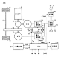
図1に示すように、車両100は、エンジン2と、動力分割機構4と、モータジェネレータ6,10と、伝達ギヤ8と、駆動軸12と、車輪14と、蓄電装置16と、電力変換器18,20と、充電器22と、充電口24と、ECU(Electronic Control Unit)26と、記憶部27と、EV優先スイッチ28と、冷却システム30とを含む。車両100は、エンジン2と、モータジェネレータ10とを駆動源とするハイブリッド車両である。
As shown in FIG. 1, a
動力分割機構4は、エンジン2、モータジェネレータ6および伝達ギヤ8に結合されてこれらの間で動力を分割する。動力分割機構4として、たとえば、サンギヤ、プラネタリキャリヤおよびリングギヤの3つの回転軸を有する遊星歯車機構を用いることができる。この3つの回転軸は、エンジン2、モータジェネレータ6および伝達ギヤ8の回転軸にそれぞれ接続される。また、モータジェネレータ10の回転軸は、伝達ギヤ8の回転軸に連結される。すなわち、モータジェネレータ10と伝達ギヤ8とは、同一の回転軸を有し、その回転軸が動力分割機構4のリングギヤに接続される。
Power split device 4 is coupled to engine 2, motor generator 6, and transmission gear 8 to split power among them. As the power split mechanism 4, for example, a planetary gear mechanism having three rotation shafts of a sun gear, a planetary carrier, and a ring gear can be used. These three rotation shafts are connected to the rotation shafts of engine 2, motor generator 6 and transmission gear 8, respectively. The rotation shaft of
エンジン2が発生する運動エネルギーは、動力分割機構4によってモータジェネレータ6と伝達ギヤ8とに分配される。すなわち、エンジン2は、駆動軸12に動力を伝達する伝達ギヤ8を駆動するとともにモータジェネレータ6を駆動する動力源として車両100に組込まれる。モータジェネレータ6は、エンジン2によって駆動される発電機として動作し、かつ、エンジン2の始動を行ない得る電動機として動作するものとして車両100に組込まれる。また、モータジェネレータ10は、駆動軸12に動力を伝達する伝達ギヤ8を駆動する動力源として車両100に組込まれる。
Kinetic energy generated by the engine 2 is distributed to the motor generator 6 and the transmission gear 8 by the power split mechanism 4. That is, engine 2 is incorporated in
蓄電装置16は、充放電可能な直流電源であり、たとえば、ニッケル水素やリチウムイオン等の二次電池である。蓄電装置16は、電力変換器18,20へ電力を供給する。また、蓄電装置16は、モータジェネレータ6および/または10の発電時、電力変換器18および/または20から電力を受けて充電される。さらに、蓄電装置16は、充電口24に接続される図示されない車両外部の電源(以下「外部電源」とも称する。)からの充電時、充電器22から電力を受けて充電される。なお、蓄電装置16として、大容量のキャパシタも採用可能であり、モータジェネレータ6,10による発電電力や外部電源からの電力を一時的に蓄え、その蓄えた電力をモータジェネレータ6,10へ供給可能な電力バッファであれば如何なるものでもよい。なお、蓄電装置16には、蓄電装置16の温度TBを検出する蓄電装置温度センサ40が設けられる。蓄電装置温度センサ40は、その検出値をECU26に出力する。また、蓄電装置16の電圧VBおよび蓄電装置16に入出力される電流IBが図示されないセンサによって検出され、その検出値がECU26へ出力される。
The
電力変換器18は、ECU26からの信号PWM1に基づいて、モータジェネレータ6により発電された電力を直流電力に変換して蓄電装置16へ出力する。電力変換器20は、ECU26からの信号PWM2に基づいて、蓄電装置16から供給される直流電力を交流電力に変換してモータジェネレータ10へ出力する。なお、電力変換器18は、エンジン2の始動時、信号PWM1に基づいて、蓄電装置16から供給される直流電力を交流電力に変換してモータジェネレータ6へ出力する。また、電力変換器20は、車両の制動時や下り斜面での加速度低減時等の回生制動時に、信号PWM2に基づいて、モータジェネレータ10により発電された電力を直流電力に変換して蓄電装置16へ出力する。
Based on
モータジェネレータ6,10は、交流電動機であり、たとえばロータに永久磁石が埋設された三相交流同期電動機である。モータジェネレータ6は、エンジン2により生成された運動エネルギーを電気エネルギーに変換して電力変換器18へ出力する。また、モータジェネレータ6は、電力変換器18から受ける三相交流電力によって駆動力を発生し、エンジン2の始動を行なう。
モータジェネレータ10は、電力変換器20から受ける三相交流電力によって車両の駆動トルクを発生する。また、モータジェネレータ10は、車両の制動時や下り斜面での加速度低減時等の回生制動時に、運動エネルギーや位置エネルギーとして車両に蓄えられた力学的エネルギーを電気エネルギーに変換して電力変換器20へ出力する。
エンジン2は、燃料の燃焼による熱エネルギーをピストンやロータなどの運動子の運動エネルギーに変換し、その変換された運動エネルギーを動力分割機構4へ出力する。たとえば、運動子がピストンであり、その運動が往復運動であれば、いわゆるクランク機構を介して往復運動が回転運動に変換され、ピストンの運動エネルギーが動力分割機構4に伝達される。 The engine 2 converts thermal energy generated by fuel combustion into kinetic energy of a moving element such as a piston or a rotor, and outputs the converted kinetic energy to the power split mechanism 4. For example, if the motion element is a piston and the motion is a reciprocating motion, the reciprocating motion is converted into a rotational motion via a so-called crank mechanism, and the kinetic energy of the piston is transmitted to the power split mechanism 4.
充電器22は、ECU26からの信号PWM3に基づいて、充電口24に与えられる外部電源からの電力を蓄電装置16の電圧レベルに変換して蓄電装置16へ出力する。充電口24は、外部電源から蓄電装置16へ電力を供給するための外部充電インターフェースである。
Based on signal PWM <b> 3 from
ECU26は、電力変換器18,20をそれぞれ駆動するための信号PWM1,PWM2を生成し、その生成した信号PWM1,PWM2をそれぞれ電力変換器18,20へ出力する。また、ECU26は、充電器22による蓄電装置16の充電を要求する信号CHRGを受けると、充電器22を駆動するための信号PWM3を生成し、その生成した信号PWM3を充電器22へ出力する。
さらに、ECU26は、この車両100の走行モードの切替を制御する。すなわち、ECU26は、エンジン2を停止した状態でモータジェネレータ10のみを用いての走行を優先させる電動機走行優先モード(以下「EV(Electric Vehicle)優先モード」とも称する。)とするか、それともエンジン2を動作させて蓄電装置16の充電状態(以下「SOC(State of Charge)」とも称する。)を所定の目標に維持するハイブリッド走行モード(以下「HV(Hybrid Vehicle)モード」とも称する。)とするかの切替を制御する。なお、SOCは、蓄電装置16の満充電状態に対する蓄電量を0〜100%で表わしたものであり、蓄電装置16の蓄電残量を示す。
Further, the
なお、EV優先モードにおける「優先」とは、蓄電装置16のSOCを所定の目標に維持することなく、原則として、エンジン2を停止した状態でモータジェネレータ10のみを用いて走行することを意味する。すなわち、運転者によりアクセルペダルが大きく踏込まれるとき、エンジン駆動タイプのエアコン動作時やエンジン暖機時などは、例外的にエンジン2の動作が許容される。
Note that “priority” in the EV priority mode means that, in principle, the vehicle 2 travels using only the
蓄電装置16のSOCを目標値に維持しないで走行するEV優先モードとは、駆動力的に必要がない限りはエンジン2を始動させず、基本的に蓄電装置16の充電電力をモータジェネレータ10で消費して車両を走行させるモードのことである。このEV優先モードの間は、結果的に充電よりも放電の割合の方が相対的に大きくなることが多い。
In the EV priority mode in which the vehicle travels without maintaining the SOC of the
また、HVモードは、蓄電装置16のSOCを所定の目標値に維持するために、エンジン2を動作させてモータジェネレータ6により発電を行なう走行状態を意味し、エンジン2を常時動作させての走行に限定されるものではない。
The HV mode means a running state in which the engine 2 is operated and the motor generator 6 generates power to maintain the SOC of the
また、以下の説明においては、エンジン2を停止した状態でモータジェネレータ10のみを用いて車両100が走行することを「EV走行」といい、エンジン2およびモータジェネレータ10を用いて車両100が走行することを「HV走行」という。したがって、EV優先モードにおいてもHVモードにおいても車両100の状態に応じてEV走行およびHV走行のうちのいずれか一方が選択されることとなる。
In the following description, the
ECU26は、さらに、EV優先スイッチ28から信号FLGを受ける。この信号FLGは、利用者によりEV優先スイッチ28に入力される走行モードの切替要求に応じて変化する。ECU26は、信号FLGに基づいて利用者によりEV優先モードからHVモードへの切替が要求されたと判断した場合、そのときの蓄電装置16のSOCを記憶部27へ出力する。ECU26は、信号FLG、蓄電装置16のSOCおよび記憶部27に記憶されたモード切替要求時のSOCに基づいて走行モードの切替を制御する。
また、EV優先スイッチ28には、走行モードに応じて点灯/消灯が切替わる表示部が設けられている。ECU26は、EV優先スイッチ28からの信号FLGに基づいて、EV優先スイッチ28に設けられた表示部の点灯状態を制御するための信号DISPを生成し、その生成した信号DISPをEV優先スイッチ28へ出力する。また、SOCのレベルによっては、EV優先スイッチ28からの操作入力に応じて直ちに走行モードが切替わらない場合もあるが、このときECU26は、実際の走行モードに応じてではなく、利用者のモード切替要求を示す信号FLGに応じてEV優先スイッチ28の表示部の点灯状態を制御する。
Further, the
記憶部27は、EV優先モードからHVモードへの切替が要求されたとECU26により判断されたとき、ECU26から出力されるそのときの蓄電装置16のSOCを記憶保持する。
When the
EV優先スイッチ28は、走行モードの切替を利用者が要求し、かつ、その要求がシステム側に認知されていることを利用者に報知するためのインターフェース装置である。EV優先スイッチ28は、利用者にオン操作されると、ECU26へ出力される信号FLGを活性化し、利用者にオフ操作されると、信号FLGを非活性化する。なお、充電器22による蓄電装置16の充電終了後は、走行モードがEV優先モードにデフォルト設定され、EV優先スイッチ28もオン状態にデフォルト設定される(すなわち、信号FLGは活性化される。)。
The
さらに、EV優先スイッチ28は、点灯/消灯を切替可能な表示部を有しており、ECU26からの信号DISPに応じて表示部の表示状態を切替える。具体的には、EV優先スイッチ28は、利用者によってオン操作されると(すなわちEV優先モードへの切替要求時)、信号DISPに基づいてランプを点灯し、利用者によってオフ操作されると(すなわちHVモードへの切替要求時)、信号DISPに基づいてランプを消灯する。
Furthermore, the
冷却システム30は、電力変換器18,20を冷却する。冷却システム30は、冷却水通路32と、ウォーターポンプ34と、ラジエータ36と、冷却水温度センサ38とを含む。なお、冷却システム30は、電力変換器18,20に加えて、モータジェネレータ6,10、エンジン2のうちの少なくともいずれか一つを冷却するようにしてもよい。
The
冷却水通路32の内部には、冷却水等の冷却媒体が流通する。冷却水通路32は、電力変換器18,20に隣接しており、冷却水通路32の内部を流通する冷却水には、電力変換器18,20において生じた熱が伝達される。冷却水通路32は、ウォーターポンプ34およびラジエータ36を経由する循環通路である。ウォーターポンプ34は、冷却水通路32の内部の冷却水を冷却水通路32の経路に沿って循環させる。ラジエータ36は、外気との熱交換によって、電力変換器18,20から伝達した熱によって温度が上昇した冷却水を放熱するための熱交換器である。
A cooling medium such as cooling water flows through the cooling
冷却水温度センサ38は、冷却水通路32内の冷却水の温度Twを検出し、検出した冷却水の温度Twを示す信号をECU26に送信する。なお、ウォーターポンプ34は、車両100のシステムが起動するとともに作動してもよいし、電力変換器18,20の起動とともに作動するようにしてもよい。
The cooling
以上のような構成を有する車両100において、エンジン2を停止させ、モータジェネレータ10によるEV走行を長時間継続して実施するためには、大容量の蓄電装置を搭載することに加えて、登坂走行や頻繁な加速等による負荷の増加に対応できる走行パワーを発生させることが必要となる。
In the
そのため、ECU26は、図2に示すように、たとえば、蓄電装置16の温度が予め定められた温度TB(0)以上であって、かつ、冷却水の温度Twが後述する第1温度Tw(0)よりも小さいT1である場合に、EV走行しているときは、HV走行しているときよりも蓄電装置16の温度TBに応じた放電電力の上限値を増加させて蓄電装置16の放電電力を制御する。
Therefore, as shown in FIG. 2, for example,
すなわち、蓄電装置16の温度TBが予め定められた値TB(0)以上となる温度TB(1)である場合において、温度TB(1)に応じたEV走行時の蓄電装置16の放電電力の上限値Wev(=W(0))を、温度TB(1)に応じたHV走行時の蓄電装置16の放電電力の上限値Whv(=W(1))よりも増加させる。これによって、長時間継続してEV走行を実施するために必要な走行パワーを確保することができる。
That is, when temperature TB of
なお、図2は、蓄電装置の温度TBとEV走行時の放電電力の上限値WevおよびHV走行時の放電電力の上限値Whvの各々との関係を示す図である。図2の縦軸は、放電電力の上限値Woutを示し、図2の横軸は、蓄電装置16の温度TBを示す。また、第1温度Tw(0)は、冷却水の温度Twに応じた蓄電装置16の放電電力の上限値Woutの制限のしきい値となる冷却水の温度Twを示す。
FIG. 2 is a diagram showing the relationship between the temperature TB of the power storage device and each of the upper limit value Wev of discharge power during EV traveling and the upper limit value Whv of discharge power during HV traveling. The vertical axis in FIG. 2 indicates the upper limit value Wout of the discharge power, and the horizontal axis in FIG. 2 indicates the temperature TB of the
しかしながら、EV走行時に必要な走行パワーを得るために、上述のようにEV走行時にHV走行時よりも蓄電装置16の放電電力の上限値Woutを拡大させる場合には、EV走行時の電力変換器20の発熱量がHV走行時の発熱量よりも増加するため、電力変換器20に含まれる半導体素子等の部品の劣化が促進する可能性がある。
However, in order to obtain traveling power required during EV traveling, as described above, when the upper limit value Wout of the discharge power of
また、冷却水の温度Twに基づいて冷却システム30が異常であると判定された時点で電力供給の上限値を急激に低下させて制限をする場合には、電力供給の制限が開始された直後から急に、運転者の意図する走行性能を発揮できなくなる場合がある。
Further, when the
そこで、本実施例においては、ECU26が、冷却水の温度Twに応じて蓄電装置16の放電電力の上限値を決定する点に特徴を有する。特に、ECU26は、冷却水の温度Twが第1温度Tw(0)から第2温度Tw(1)まで上昇する場合に、EV走行しているときの冷却水の温度Twの上昇に応じた上限値Wevの減少率が、HV走行しているときの冷却水の温度Twの上昇に応じた上限値Whvの減少率よりも大きくなるように蓄電装置16の放電電力の上限値Wevを決定する。
Therefore, the present embodiment is characterized in that the
図3に、本実施例に係る車両用制御装置であるECU26の機能ブロック図を示す。図3に示すように、ECU26は、温度判定部102と、第1制限制御部104と、第2制限制御部106と、通常制御部108とを含む。
FIG. 3 is a functional block diagram of the
温度判定部102は、冷却水の温度Twが第1温度Tw(0)以上であるか否かを判定する。さらに、温度判定部102は、冷却水の温度Twが第2温度Tw(1)よりも小さいか否かを判定する。
The
第1温度Tw(0)は、後述する第2温度Tw(1)よりも小さい温度である。第2温度Tw(1)は、HV走行時の上限値WhvをEV走行時の上限値Wevとして決定する温度である。第2温度Tw(1)は、たとえば、冷却装置30が異常状態であると判定するためのしきい値と同一の温度であってもよいし、あるいは、冷却装置30が異常状態であると判定するためのしきい値よりも低い温度であってもよい。第1温度Tw(0)および第2温度Tw(1)は、たとえば、実験等によって適合すればよい。
The first temperature Tw (0) is a temperature lower than a second temperature Tw (1) described later. The second temperature Tw (1) is a temperature that determines the upper limit value Whv during HV traveling as the upper limit value Wev during EV traveling. The second temperature Tw (1) may be, for example, the same temperature as the threshold for determining that the
冷却装置30の異常状態は、たとえば、冷却装置30の構成部品の故障等によって所定の冷却性能が発揮できない状態や電力変換器の温度上昇によって冷却水の温度Twが高温となる状態を含む。
The abnormal state of the
なお、温度判定部102は、たとえば、冷却水の温度Twが第1温度Tw(0)以上であると判定された場合に、第1温度判定フラグをオンするようにしてもよい。また、温度判定部102は、たとえば、冷却水の温度Twが第2温度Tw(1)よりも小さい場合に、第2温度判定フラグをオンするようにしてもよい。
Note that the
第1制限制御部104は、車両100のEV走行時において、冷却水の温度Twが第1温度Tw(0)以上であると判定された場合であって、かつ、第2温度Tw(1)よりも小さい場合に、蓄電装置16の放電電力を制限する第1制限制御を実行する。
The first
第1制限制御部104は、車両100のEV走行時に、冷却水の温度Twが第1温度Tw(0)から第2温度Tw(1)まで上昇する場合に、EV走行しているときの冷却水の温度Twの上昇に応じた蓄電装置16の放電電力の上限値Wevの減少率が、HV走行しているときの冷却水の温度Twの上昇に応じた蓄電装置16の放電電力の上限値Whvの減少率よりも大きくなるように放電電力の上限値Wevを決定して、決定された上限値Wevを超えないように蓄電装置16の放電電力を制御する。
The first
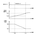
具体的には、EV走行時においては、図4に示すように、第1制限制御部104は、冷却水の温度Twが第1温度Tw(0)から第2温度Tw(1)まで上昇する場合に、冷却水の温度Twの上昇に対して線形に放電電力の上限値をW(0)からW(1)まで減少させるようにして上限値Wevを決定する。
Specifically, during EV travel, as shown in FIG. 4, the first
図4は、蓄電装置16の温度TBがTB(1)である場合の、冷却水の温度TwとEV走行時の放電電力の上限値WevおよびHV走行時の放電電力の上限値Whvの各々との関係を示す図である。図4の縦軸は、蓄電装置16の放電電力の上限値Woutを示し、図4の横軸は、冷却水の温度Twを示す。
FIG. 4 shows the cooling water temperature Tw, the upper limit value Wev of the discharge power during EV travel, and the upper limit value Whv of the discharge power during HV travel when the temperature TB of the
冷却水の温度Twが第1温度Tw(0)から第2温度Tw(1)まで上昇する場合の冷却水の温度Twの上昇に対する上限値Wevの変化量ΔWは、たとえば、ΔW=(W(1)−W(0))/(Tw(1)−Tw(0))の式より算出してもよいし、予め定められた値であってもよい。なお、上限値Wevの決定に際しては、図4に示す関係に基づいて作成されたマップ、数式あるいは表等を用いればよい。 The amount of change ΔW of the upper limit value Wev with respect to the increase in the temperature Tw of the cooling water when the temperature Tw of the cooling water rises from the first temperature Tw (0) to the second temperature Tw (1) is, for example, ΔW = (W ( 1) It may be calculated from the equation -W (0)) / (Tw (1) -Tw (0)) or may be a predetermined value. In determining the upper limit value Wev, a map, a mathematical expression, a table, or the like created based on the relationship shown in FIG. 4 may be used.
第1制限制御部104は、たとえば、蓄電装置16の温度TBと図2に示した温度TBと上限値Wevとの関係とに基づいて上限値を暫定的に決定し、冷却水の温度Twの実測値と第1温度Tw(0)との差分にΔWを乗算した値を加算して最終的な上限値Wevを決定するようにしてもよい。
For example, first
一方、HV走行時においては、図4に示すように、蓄電装置16の温度TBが変化しない限り、冷却水の温度Twの変化に関わらず、上限値W(0)が放電電力の上限値Whvとして決定される。なお、HV走行時であっても冷却水の温度Twの変化に応じて上限値Whvを変えても良い。この場合は、上限値Wevの減少率>上限値Whvの減少率となるように制御が行なわれる。
On the other hand, during HV traveling, as shown in FIG. 4, unless temperature TB of
なお、本実施例においては、第1制限制御部104は、冷却水の温度Twが第1温度Tw(0)から第2温度Tw(1)まで上昇する場合に制御を実行するが、第1制限制御部104は、たとえば、第1温度判定フラグおよび第2判定フラグのいずれもがオンされた場合に、第1制限制御を実行するようにすればよい。
In the present embodiment, the first
本実施例においては、第1制限制御部104は、冷却水の温度Twが第1温度Tw(0)から第2温度Tw(1)まで上昇する場合に、冷却水の温度Twの上昇に対して放電電力の上限値を単調減少させることができればよく、特に、W(0)からW(1)まで線形に減少させることに限定されるものではない。たとえば、第1制限制御部104は、W(0)よりも小さく、かつ、W(1)よりも大きいW(2)から、W(1)と異なり、かつ、W(2)よりも小さいW(3)まで冷却水の温度Twの上昇に対して放電電力の上限値を線形に減少または単調減少させるようにして上限値Wevを決定するようにしてもよい。
In the present embodiment, the first
さらに、冷却水の温度Twが第1温度Tw(0)から第2温度Tw(1)まで上昇する場合に、冷却水の温度Twの上昇に対して上限値Wevを線形に減少させることに限定されるものではなく、たとえば、階段状に減少させてもよいし、非線形に減少させてもよい。 Furthermore, when the temperature Tw of the cooling water rises from the first temperature Tw (0) to the second temperature Tw (1), it is limited to linearly decreasing the upper limit value Wev with respect to the increase in the temperature Tw of the cooling water. For example, it may be reduced stepwise or non-linearly.
第2制限制御部106は、車両100のEV走行時において、冷却水の温度Twが第2温度Tw(1)以上である場合に、蓄電装置16の放電電力を制限する第2制限制御を実行する。第2制限制御部106は、たとえば、第1温度判定フラグがオンであって、かつ、第2温度判定フラグがオフである場合に、第2制限制御を実行するようにすればよい。
Second
第2制限制御部106は、車両100のEV走行時において、冷却水の温度Twが第2温度Tw(1)以上である場合に、HV走行時の放電電力の上限値WhvをEV走行時の放電電力の上限値Wevとして決定して、決定された上限値Wevを超えないように蓄電装置16の放電電力を制御する。
When the coolant temperature Tw is equal to or higher than the second temperature Tw (1) during EV travel of the
なお、本実施例においては、第2制限制御部106は、冷却水の温度Twが第2温度Tw(1)以上である場合、蓄電装置16の温度TBに応じて変化する上限値Whvと同一の値であるとして説明するが、蓄電装置16の温度TBに関わらず、一定の上限値を上限値Wevとして決定するようにしてもよい。
In the present embodiment, the second
通常制御部108は、車両100のEV走行時において、冷却水の温度Twが第1温度Tw(0)よりも小さいと判定された場合に、蓄電装置16の放電電力について通常制御を実行する。通常制御部108は、たとえば、第1温度判定フラグおよび第2温度判定フラグのいずれもがオフである場合に、蓄電装置16の放電電力について通常制御を行なうようにすればよい。
The
すなわち、通常制御部108は、冷却水の温度Twが第1温度Tw(0)よりも小さいと判定された場合に、図2に示した蓄電装置16の温度TBと放電電力の上限値Wevとの関係に基づいて上限値Wevを決定して、決定された上限値Wevを超えないように蓄電装置16の放電電力を制御する。
That is, when it is determined that the temperature Tw of the cooling water is lower than the first temperature Tw (0), the
本実施例において、温度判定部102と、第1制限制御部104と、第2制限制御部106と、通常制御部108とは、いずれもECU26のCPUがメモリに記憶されたプログラムを実行することにより実現される、ソフトウェアとして機能するものとして説明するが、ハードウェアにより実現されるようにしてもよい。なお、このようなプログラムは記憶媒体に記録されて車両100に搭載される。
In the present embodiment, the
図5を参照して、本実施例に係る車両用制御装置であるECU26で実行されるプログラムの制御構造について説明する。なお、このプログラムは、EV走行時にECU26によって実行される。ECU26は、車両100の状態(たとえば、車速、エンジン回転数等)に基づいてEV走行時であるか否かを判定すればよい。
With reference to FIG. 5, a control structure of a program executed by the
ステップ(以下、ステップをSと記載する)100にて、ECU26は、冷却システム30の冷却水の温度Twが第1温度Tw(0)以上であるか否かを判定する。冷却システム30の冷却水の温度Twが第1温度Tw(0)以上であると判定された場合(S100にてYES)、処理はS102に移される。もしそうでない場合(S100にてNO)、処理はS108に移される。
In step (hereinafter, step is referred to as S) 100,
S102にて、ECU26は、冷却水の温度Twが第2温度Tw(1)よりも小さいか否かを判定する。冷却水の温度Twが第2温度Tw(1)よりも小さい場合(S102にてYES)、処理はS104に移される。もしそうでない場合(S102にてNO)、処理はS106に移される。
In S102, the
S104にて、ECU26は、第1制限制御を実行する。S106にて、ECU256は、第2制限制御を実行する。S108にて、ECU26は、通常制御を実行する。なお、第1制限制御、第2制限制御および通常制御については、上述した通りであるため、その詳細な説明は繰返さない。
In S104, the
以上のような構造およびフローチャートに基づく本実施例に係る車両用制御装置であるECU26の動作について図6を用いて説明する。なお、説明の便宜上、蓄電装置16の温度TBは、TB(1)であるとする。
The operation of the
たとえば、EV走行モードが選択された状態で車両100が走行している場合を想定する。SOCがEV走行が可能なしきい値以上であることによって、車両100がEV走行の継続が可能であるとECU26において判定された場合、ECU26は、エンジン2を停止させた状態で、モータジェネレータ10を用いて車両100をEV走行させる。
For example, it is assumed that
時間T(0)になるまでは、冷却水の温度Twが第1温度Tw(0)よりも小さいため(S100にてNO)、ECU26は、通常制御を実行する(S108)。
Until the time T (0), since the temperature Tw of the cooling water is lower than the first temperature Tw (0) (NO in S100), the
すなわち、ECU26は、図2に示した蓄電装置16の温度TBと上限値Wevとの関係に基づいて蓄電装置16の放電電力の上限値W(0)を決定する。そのため、ECU26は、上限値W(0)を超えないように蓄電装置16の放電電力を制御する。
That is,
一方、車両100が登坂走行を継続したり、あるいは、加速を頻繁に繰返したりするなどして電力変換器20に流れる電流量が増加した場合に、電力変換器20の発熱量は増加する。電力変換器20の発熱量の増加とともに、電力変換器20の温度が上昇するため、冷却水の温度Twも上昇していく。
On the other hand, when the amount of current flowing through the
時間T(0)にて、冷却水の温度Twが第1温度Tw(0)以上となった場合であって(S100にてYES)、かつ、第2温度Tw(1)よりも小さい場合(S102にてYES)、ECU26は、第1制限制御を実行する(S104)。
When the temperature Tw of the cooling water becomes equal to or higher than the first temperature Tw (0) at time T (0) (YES in S100) and is lower than the second temperature Tw (1) ( In S102, the
すなわち、ECU26は、時間T(0)から時間T(1)までの間、冷却水の温度Twが第1温度Tw(0)から第2温度Tw(1)まで上昇する場合に、冷却水の温度Twの上昇に比例して上限値が減少するように上限値Wevを決定する。ECU26は、決定された上限値Wevを超えないように蓄電装置16の放電電力を制御する。
That is, when the temperature Tw of the cooling water rises from the first temperature Tw (0) to the second temperature Tw (1) from the time T (0) to the time T (1), the
時間T(1)にて、冷却水の温度Twが第2温度Tw(1)以上となる場合(S102にてNO)には、ECU26は、第2制限制御を実行する(S106)。
When the temperature Tw of the cooling water becomes equal to or higher than the second temperature Tw (1) at time T (1) (NO in S102), the
すなわち、ECU26は、図3に示す蓄電装置16の温度TBと上限値Whvとの関係に基づいて蓄電装置16の放電電力の上限値WhvであるW(1)を上限値Wevとして決定する。ECU26は、上限値W(1)を超えないように蓄電装置16の放電電力を制御する。
That is,
本実施例において、冷却水の温度Twが第1温度Tw(0)から第2温度Tw(1)まで上昇する場合には、冷却水の温度Twの上昇に対して上限値Wevは線形で減少する。そのため、冷却水の温度Twがたとえば、第2温度Tw(1)以上になった直後に蓄電装置16の放電電力の上限値W(0)をW(1)までステップ的に低下させた場合に比べて、蓄電装置16の放電電力は緩やかに制限されることとなる。
In this embodiment, when the temperature Tw of the cooling water rises from the first temperature Tw (0) to the second temperature Tw (1), the upper limit value Wev decreases linearly with respect to the increase in the temperature Tw of the cooling water. To do. Therefore, for example, when upper limit value W (0) of the discharge power of
さらに、本実施例においては、EV走行時に冷却水の温度Twが冷却装置30が異常状態であることを示す第2温度Tw(1)以上となる場合には、EV走行時の上限値WevをHV走行時の上限値Whvとすることによって、EV走行を長時間継続して実施することに起因した電力変換器20に含まれる部品に対して熱による影響の発生が回避される。
Furthermore, in this embodiment, when the temperature Tw of the cooling water during EV traveling is equal to or higher than the second temperature Tw (1) indicating that the
以上のようにして、本実施例に係る車両用制御装置によると、冷却水の温度Twが第1温度Tw(0)から第2温度Tw(1)まで上昇した場合に、EV走行しているときの冷却水の温度Twの上昇に応じた放電電力の上限値Wevの減少率が、HV走行しているときの冷却水の温度Twの上昇に応じた放電電力の上限値Whvの減少率よりも大きくなるように上限値Wevが決定される。これにより、EV走行時にHV走行時よりも蓄電装置の放電電力の上限値Woutを拡大させて長時間継続してEV走行をする場合に、電力変換器に含まれる半導体等の部品の劣化の促進を防止することができる。したがって、蓄電装置の放電電力の増加に起因した電動機を作動させるための電気機器の熱による影響の発生を抑制する車両用制御装置および車両用制御方法を提供することができる。 As described above, according to the vehicle control apparatus of the present embodiment, EV traveling is performed when the temperature Tw of the cooling water rises from the first temperature Tw (0) to the second temperature Tw (1). The decrease rate of the upper limit value Wev of the discharge power according to the rise in the temperature Tw of the cooling water at the time is smaller than the decrease rate of the upper limit value Whv of the discharge power according to the increase in the temperature Tw of the coolant when traveling in HV The upper limit value Wev is determined so as to be larger. As a result, when EV travel is continued for a long time by increasing the upper limit value Wout of the discharge power of the power storage device during EV travel, compared with during HV travel, the deterioration of components such as semiconductors included in the power converter is promoted. Can be prevented. Therefore, it is possible to provide a vehicle control device and a vehicle control method that suppress the occurrence of an influence caused by heat of an electric device for operating an electric motor due to an increase in discharge power of a power storage device.
さらに、冷却水の温度Twが第1温度Tw(0)から第2温度Tw(1)に上昇する場合に、冷却水の温度Twの上昇に対して線形に上限値Wevが減少するように上限値を決定することによって、冷却水の温度Twに応じた蓄電装置の放電電力の上限値Wevの減少の程度を緩やかにすることができる。したがって、内燃機関を停止させた状態で、回転電機により車両が走行する場合に、電気機器の冷却水の温度に応じた電力供給の制限を緩やかにする車両用制御装置および車両用制御方法を提供することができる。 Furthermore, when the temperature Tw of the cooling water rises from the first temperature Tw (0) to the second temperature Tw (1), the upper limit is set so that the upper limit value Wev decreases linearly with respect to the increase in the temperature Tw of the cooling water. By determining the value, the degree of decrease in the upper limit value Wev of the discharge power of the power storage device according to the temperature Tw of the cooling water can be moderated. Accordingly, there is provided a vehicle control device and a vehicle control method that loosely restricts the supply of electric power according to the temperature of cooling water in an electric device when the vehicle is driven by a rotating electrical machine with the internal combustion engine stopped. can do.
今回開示された実施例はすべての点で例示であって制限的なものではないと考えられるべきである。本発明の範囲は上記した説明ではなくて請求の範囲によって示され、請求の範囲と均等の意味および範囲内でのすべての変更が含まれることが意図される。 It should be understood that the embodiments disclosed herein are illustrative and non-restrictive in every respect. The scope of the present invention is defined by the terms of the claims, rather than the description above, and is intended to include any modifications within the scope and meaning equivalent to the terms of the claims.
2 エンジン、4 動力分割機構、6,10 モータジェネレータ、8 伝達ギヤ、10 モータジェネレータ、12 駆動軸、14 車輪、16 蓄電装置、18,20 電力変換器、22 充電器、24 充電口、27 記憶部、28 EV優先スイッチ、30 冷却システム、32 冷却水通路、34 ウォーターポンプ、36 ラジエータ、38 冷却水温度センサ、40 蓄電装置温度センサ、100 車両、102 温度判定部、104 第1制限制御部、106 第2制限制御部、108 通常制御部。 2 engine, 4 power split mechanism, 6, 10 motor generator, 8 transmission gear, 10 motor generator, 12 drive shaft, 14 wheels, 16 power storage device, 18, 20 power converter, 22 charger, 24 charging port, 27 memory , 28 EV priority switch, 30 cooling system, 32 cooling water passage, 34 water pump, 36 radiator, 38 cooling water temperature sensor, 40 power storage device temperature sensor, 100 vehicle, 102 temperature determination unit, 104 first restriction control unit, 106 Second limit control unit, 108 Normal control unit.
Claims (5)
前記車両用制御装置は、
前記冷却媒体の温度を検出するための媒体温度検出部(38)と、
前記冷却媒体の温度に応じて前記蓄電装置(16)の放電電力の上限値を決定し、決定された前記上限値を超えないように前記蓄電装置(16)の放電電力を制御するための制御部(26)とを備え、
前記制御部(26)は、前記冷却媒体の温度が第1温度から第2温度まで上昇する場合に、前記内燃機関(2)を停止させた状態で前記回転電機(10)の動力を用いて走行する第1の走行状態で前記車両(100)が走行しているときの前記冷却媒体の温度の上昇に応じた前記上限値の減少率が、前記内燃機関(2)の動力と前記回転電機(10)の動力とをともに用いて走行する第2の走行状態で前記車両(100)が走行しているときの前記冷却媒体の温度の上昇に応じた前記上限値の減少率よりも大きくなるように前記上限値を決定する、車両用制御装置。A vehicle control device mounted on a vehicle (100) having an internal combustion engine (2) and a rotating electrical machine (10) as drive sources, the vehicle (100) including the rotating electrical machine (10) and the rotating Electric device (20) that operates as the electric machine (10) is driven, power is supplied to the rotating electric machine (10) and the electric device (20), and charging is possible using an external power source. A power storage device (16), and a cooling device (30) for cooling the electric device (20) using a cooling medium,
The vehicle control device includes:
A medium temperature detector (38) for detecting the temperature of the cooling medium;
Control for determining an upper limit value of the discharge power of the power storage device (16) according to the temperature of the cooling medium and controlling the discharge power of the power storage device (16) so as not to exceed the determined upper limit value Part (26),
The controller (26) uses the power of the rotating electrical machine (10) with the internal combustion engine (2) stopped when the temperature of the cooling medium rises from the first temperature to the second temperature. When the vehicle (100) is traveling in the first traveling state in which the vehicle travels, the reduction rate of the upper limit value according to the rise in the temperature of the cooling medium is determined by the power of the internal combustion engine (2) and the rotating electrical machine. When the vehicle (100) is traveling in the second traveling state that travels together with the power of (10), the rate of increase is greater than the decrease rate of the upper limit value according to the temperature increase of the cooling medium. The vehicle control device determines the upper limit value as described above.
前記制御部(26)は、前記蓄電装置(16)の温度が予め定められた温度以上であって、かつ、前記冷却媒体の温度が前記第1温度以下である場合に、前記第1の走行状態で前記車両(100)が走行しているときは、前記第2の走行状態で前記車両(100)が走行しているときよりも、前記蓄電装置の温度に応じた前記放電電力の上限値を増加させて前記蓄電装置(16)の放電電力を制御する、請求の範囲第1項に記載の車両用制御装置。The vehicle control device further includes a power storage device temperature detection unit (40) for detecting the temperature of the power storage device (16),
The control unit (26) performs the first traveling when the temperature of the power storage device (16) is equal to or higher than a predetermined temperature and the temperature of the cooling medium is equal to or lower than the first temperature. When the vehicle (100) is traveling in the state, the upper limit value of the discharge power according to the temperature of the power storage device is greater than when the vehicle (100) is traveling in the second traveling state. The vehicle control device according to claim 1, wherein discharge power of the power storage device (16) is controlled by increasing the power.
前記車両用制御方法は、
前記冷却媒体の温度を検出するステップと、
前記冷却媒体の温度に応じて前記蓄電装置(16)の放電電力の上限値を決定し、前記上限値を決定するステップにて決定された前記上限値を超えないように前記蓄電装置(16)の放電電力を制御するステップとを備える、
前記制御するステップは、前記冷却媒体の温度が第1温度から第2温度まで上昇する場合に、前記内燃機関(2)を停止させた状態で前記回転電機(10)の動力を用いて走行する第1の走行状態で前記車両(100)が走行しているときの前記冷却媒体の温度の上昇に応じた前記上限値の減少率が、前記内燃機関(2)の動力と前記回転電機(10)の動力とをともに用いて走行する第2の走行状態で前記車両(100)が走行しているときの前記冷却媒体の温度の上昇に応じた前記上限値の減少率よりも大きくなるように前記上限値を決定する、車両用制御方法。A control method for a vehicle mounted on a vehicle (100) using an internal combustion engine (2) and a rotating electrical machine (10) as driving sources, the vehicle (100) including the rotating electrical machine (10) and the rotation Electric device (20) that operates as the electric machine (10) is driven, power is supplied to the rotating electric machine (10) and the electric device (20), and charging is possible using an external power source. A power storage device (16), and a cooling device (30) for cooling the electric device (20) using a cooling medium,
The vehicle control method includes:
Detecting the temperature of the cooling medium;
The upper limit value of the discharge power of the power storage device (16) is determined according to the temperature of the cooling medium, and the power storage device (16) is not exceeded so as not to exceed the upper limit value determined in the step of determining the upper limit value. Controlling the discharge power of
In the controlling step, when the temperature of the cooling medium rises from the first temperature to the second temperature, the internal combustion engine (2) is stopped and travels using the power of the rotating electrical machine (10). When the vehicle (100) is traveling in the first traveling state, the reduction rate of the upper limit value according to the increase in the temperature of the cooling medium is the power of the internal combustion engine (2) and the rotating electrical machine (10). ) In the second traveling state in which the vehicle (100) is traveling together, the lowering rate of the upper limit value is increased in response to an increase in the temperature of the cooling medium when the vehicle (100) is traveling. A vehicle control method for determining the upper limit value.
Applications Claiming Priority (1)
| Application Number | Priority Date | Filing Date | Title |
|---|---|---|---|
| PCT/JP2010/055646 WO2011121717A1 (en) | 2010-03-30 | 2010-03-30 | Vehicle control unit and vehicle control method |
Publications (2)
| Publication Number | Publication Date |
|---|---|
| JP5177324B2 true JP5177324B2 (en) | 2013-04-03 |
| JPWO2011121717A1 JPWO2011121717A1 (en) | 2013-07-04 |
Family
ID=44711511
Family Applications (1)
| Application Number | Title | Priority Date | Filing Date |
|---|---|---|---|
| JP2012507944A Active JP5177324B2 (en) | 2010-03-30 | 2010-03-30 | VEHICLE CONTROL DEVICE AND VEHICLE CONTROL METHOD |
Country Status (5)
| Country | Link |
|---|---|
| US (1) | US20120323427A1 (en) |
| EP (1) | EP2423064A4 (en) |
| JP (1) | JP5177324B2 (en) |
| CN (1) | CN102470856B (en) |
| WO (1) | WO2011121717A1 (en) |
Families Citing this family (14)
| Publication number | Priority date | Publication date | Assignee | Title |
|---|---|---|---|---|
| US9290101B2 (en) * | 2010-11-22 | 2016-03-22 | Honda Motor Co., Ltd. | Power control unit for electric vehicle with converters cooled by surfaces of a cooling unit |
| DE102012009736A1 (en) * | 2012-05-16 | 2013-11-21 | Audi Ag | Device for displaying information in a hybrid vehicle |
| US9168844B2 (en) | 2012-07-30 | 2015-10-27 | GM Global Technology Operations LLC | Methods and systems for diagnosing performance of active cooling system in an electric vehicle |
| DE102012217711A1 (en) * | 2012-09-28 | 2014-04-03 | Magna Powertrain Ag & Co. Kg | Electric machine with cooling |
| JP6081130B2 (en) * | 2012-10-12 | 2017-02-15 | 日野自動車株式会社 | On-vehicle power control device cooling system and abnormality diagnosis method |
| JP6075018B2 (en) * | 2012-11-09 | 2017-02-08 | トヨタ自動車株式会社 | Electric vehicle control device, electric vehicle including the same, and electric vehicle control method |
| JP2014118079A (en) * | 2012-12-18 | 2014-06-30 | Mitsubishi Motors Corp | Charge control unit for hybrid vehicle |
| EP3109119B1 (en) * | 2015-06-23 | 2022-08-10 | Volvo Car Corporation | Method and arrangement for allowing secondary tasks during semi-automated driving |
| CN105207569B (en) * | 2015-10-26 | 2018-01-30 | 重庆长安汽车股份有限公司 | Motor excess temperature protection method, device and the electric car of a kind of electric car |
| KR101798516B1 (en) * | 2015-11-17 | 2017-11-16 | 현대자동차주식회사 | Motor system control method and apparatus for hybrid vehicle |
| US10381886B2 (en) * | 2016-08-01 | 2019-08-13 | Hamilton Sundstrand Corporation | Motor-generator with radial-flux double-sided stator |
| JP7227553B2 (en) * | 2018-08-27 | 2023-02-22 | 三菱自動車工業株式会社 | Battery cooling controller |
| CN109823188A (en) * | 2019-01-10 | 2019-05-31 | 乾碳国际公司 | The mixed gentle speed system of dynamic commercial vehicle regenerative braking |
| US11320844B2 (en) * | 2019-06-14 | 2022-05-03 | Ford Global Technologies, Llc | Methods and system for operating an electric power delivery device of a vehicle |
Citations (3)
| Publication number | Priority date | Publication date | Assignee | Title |
|---|---|---|---|---|
| JP2003274509A (en) * | 2002-03-15 | 2003-09-26 | Nissan Motor Co Ltd | Power converter |
| JP2005224042A (en) * | 2004-02-06 | 2005-08-18 | Toyota Motor Corp | Temperature regulating device |
| JP2010068641A (en) * | 2008-09-11 | 2010-03-25 | Toyota Motor Corp | Drive unit, method of controlling the same, and vehicle |
Family Cites Families (31)
| Publication number | Priority date | Publication date | Assignee | Title |
|---|---|---|---|---|
| US4313080A (en) * | 1978-05-22 | 1982-01-26 | Battery Development Corporation | Method of charge control for vehicle hybrid drive batteries |
| US5341077A (en) * | 1993-02-03 | 1994-08-23 | Industrial Technology Research Institute | Method and device for limiting electrical current supplied to the motor of an electric vehicle |
| JP3449226B2 (en) * | 1998-07-03 | 2003-09-22 | 日産自動車株式会社 | Battery control device for hybrid vehicle |
| US6209672B1 (en) * | 1998-09-14 | 2001-04-03 | Paice Corporation | Hybrid vehicle |
| US6464026B1 (en) * | 1998-10-09 | 2002-10-15 | John Horsley | Control system for parallel hybrid vehicle |
| US6492056B1 (en) * | 2000-03-13 | 2002-12-10 | Energy Conversion Devices, Inc. | Catalytic hydrogen storage composite material and fuel cell employing same |
| JP2002199588A (en) * | 2000-12-27 | 2002-07-12 | Hitachi Ltd | Power supply system |
| JP2003199207A (en) * | 2001-12-26 | 2003-07-11 | Aisin Aw Co Ltd | Electric vehicle drive control device, electric vehicle drive control method and program therefor |
| US6664751B1 (en) * | 2002-06-17 | 2003-12-16 | Ford Motor Company | Method and arrangement for a controlling strategy for electronic components in a hybrid electric vehicle |
| US20040069546A1 (en) * | 2002-10-15 | 2004-04-15 | Zheng Lou | Hybrid electrical vehicle powertrain thermal control |
| US6936995B2 (en) * | 2003-02-25 | 2005-08-30 | General Motors Corporation | Battery voltage reduction |
| US6809501B2 (en) * | 2003-03-11 | 2004-10-26 | General Motors Corporation | Method of improving fuel economy |
| JP4290461B2 (en) * | 2003-04-03 | 2009-07-08 | 株式会社日立製作所 | Cooling system and cooling control method for electric device |
| JP4742486B2 (en) * | 2003-04-10 | 2011-08-10 | 日産自動車株式会社 | Fuel cell power generation control device |
| US20060001399A1 (en) * | 2004-07-02 | 2006-01-05 | Lembit Salasoo | High temperature battery system for hybrid locomotive and offhighway vehicles |
| JP2006144641A (en) * | 2004-11-18 | 2006-06-08 | Toyota Motor Corp | Power output device and automobile equipped therewith, and control method for the power output device |
| JP2006271136A (en) * | 2005-03-24 | 2006-10-05 | Denso Corp | Dc-dc converter device |
| JP4577274B2 (en) * | 2006-06-06 | 2010-11-10 | 株式会社デンソー | Vehicle power supply system |
| JP2008072818A (en) * | 2006-09-13 | 2008-03-27 | Toyota Motor Corp | Cooling system and vehicle equipped with same |
| JP4862621B2 (en) * | 2006-11-15 | 2012-01-25 | トヨタ自動車株式会社 | Hybrid vehicle and control method thereof |
| JP4678374B2 (en) * | 2007-01-04 | 2011-04-27 | トヨタ自動車株式会社 | LOAD DEVICE CONTROL DEVICE AND VEHICLE |
| US8049460B2 (en) * | 2007-07-18 | 2011-11-01 | Tesla Motors, Inc. | Voltage dividing vehicle heater system and method |
| US7789794B2 (en) * | 2007-10-23 | 2010-09-07 | Ford Global Technologies, Llc | Method and system for controlling a propulsion system of an alternatively powered vehicle |
| US8140204B2 (en) * | 2007-12-10 | 2012-03-20 | Ford Global Technologies, Llc | Charge depleting energy management strategy for plug-in hybrid electric vehicles |
| US8202411B2 (en) * | 2008-03-19 | 2012-06-19 | Eltron Research & Development, Inc. | Electrowinning apparatus and process |
| JP2009254206A (en) | 2008-04-10 | 2009-10-29 | Toyota Motor Corp | Power source control system |
| JP2010241170A (en) * | 2009-04-01 | 2010-10-28 | Toyota Motor Corp | Power output apparatus, hybrid vehicle provided with the same, and method of controlling power output apparatus |
| KR101039678B1 (en) * | 2009-11-17 | 2011-06-09 | 현대자동차주식회사 | Cooling control method for invertor and ldc of hev |
| US8652676B2 (en) * | 2010-02-17 | 2014-02-18 | Hitachi, Ltd. | Assembled battery system with cooling member between adjacent cells |
| CN103402809B (en) * | 2011-01-13 | 2016-11-09 | 卡明斯公司 | For controlling system, the method and apparatus of the power output distribution in hybrid powertrain |
| JP2012248339A (en) * | 2011-05-25 | 2012-12-13 | Sanyo Electric Co Ltd | Power unit for electric power and vehicle with power unit |
-
2010
- 2010-03-30 WO PCT/JP2010/055646 patent/WO2011121717A1/en active Application Filing
- 2010-03-30 CN CN201080032521.5A patent/CN102470856B/en not_active Expired - Fee Related
- 2010-03-30 JP JP2012507944A patent/JP5177324B2/en active Active
- 2010-03-30 US US13/581,422 patent/US20120323427A1/en not_active Abandoned
- 2010-03-30 EP EP10848897.4A patent/EP2423064A4/en not_active Withdrawn
Patent Citations (3)
| Publication number | Priority date | Publication date | Assignee | Title |
|---|---|---|---|---|
| JP2003274509A (en) * | 2002-03-15 | 2003-09-26 | Nissan Motor Co Ltd | Power converter |
| JP2005224042A (en) * | 2004-02-06 | 2005-08-18 | Toyota Motor Corp | Temperature regulating device |
| JP2010068641A (en) * | 2008-09-11 | 2010-03-25 | Toyota Motor Corp | Drive unit, method of controlling the same, and vehicle |
Also Published As
| Publication number | Publication date |
|---|---|
| WO2011121717A1 (en) | 2011-10-06 |
| CN102470856A (en) | 2012-05-23 |
| US20120323427A1 (en) | 2012-12-20 |
| CN102470856B (en) | 2014-03-12 |
| EP2423064A1 (en) | 2012-02-29 |
| EP2423064A4 (en) | 2018-04-11 |
| JPWO2011121717A1 (en) | 2013-07-04 |
Similar Documents
| Publication | Publication Date | Title |
|---|---|---|
| JP5177324B2 (en) | VEHICLE CONTROL DEVICE AND VEHICLE CONTROL METHOD | |
| US8098050B2 (en) | Charge/discharge control device for secondary battery and vehicle equipped with the same | |
| JP5370584B2 (en) | Hybrid vehicle | |
| JP5692405B2 (en) | Vehicle and vehicle control method | |
| JP6363493B2 (en) | Hybrid vehicle | |
| JP5981439B2 (en) | Control device for hybrid vehicle | |
| JP4595829B2 (en) | Secondary battery control device and control method | |
| JP6024584B2 (en) | Hybrid vehicle | |
| JP5747724B2 (en) | Vehicle and vehicle control method | |
| JP6213497B2 (en) | Hybrid vehicle | |
| JP4321641B2 (en) | Hybrid vehicle, control method of hybrid vehicle, and computer-readable recording program for causing computer to execute the control method | |
| JP5104708B2 (en) | Control device and control method for hybrid vehicle | |
| JP2011086628A (en) | Electric storage unit cooling device | |
| JP2015098209A (en) | Hybrid vehicle | |
| JP5382232B2 (en) | Engine control apparatus and control method | |
| JP6075018B2 (en) | Electric vehicle control device, electric vehicle including the same, and electric vehicle control method | |
| JP2012019587A (en) | Electric motor vehicle | |
| JP2014007905A (en) | Controller for motor drive system | |
| JP2009040322A (en) | Control device of hybrid vehicle | |
| JP2014184799A (en) | Travel control device for electric vehicle | |
| JP5880818B2 (en) | Hybrid vehicle and control method thereof | |
| JP2015217828A (en) | Hybrid electric vehicle control unit | |
| JP2013001372A (en) | Control device of hybrid vehicle, hybrid vehicle having the same, and control method of hybrid vehicle | |
| JP2012207709A (en) | Vehicle and vehicle control method | |
| JP2012158310A (en) | Vehicle |
Legal Events
| Date | Code | Title | Description |
|---|---|---|---|
| TRDD | Decision of grant or rejection written | ||
| A01 | Written decision to grant a patent or to grant a registration (utility model) |
Free format text: JAPANESE INTERMEDIATE CODE: A01 Effective date: 20121211 |
|
| A61 | First payment of annual fees (during grant procedure) |
Free format text: JAPANESE INTERMEDIATE CODE: A61 Effective date: 20121224 |
|
| R151 | Written notification of patent or utility model registration |
Ref document number: 5177324 Country of ref document: JP Free format text: JAPANESE INTERMEDIATE CODE: R151 |
|
| FPAY | Renewal fee payment (event date is renewal date of database) |
Free format text: PAYMENT UNTIL: 20160118 Year of fee payment: 3 |