JP5177076B2 - Vehicle driving support device and vehicle driving support method - Google Patents
Vehicle driving support device and vehicle driving support method Download PDFInfo
- Publication number
- JP5177076B2 JP5177076B2 JP2009122834A JP2009122834A JP5177076B2 JP 5177076 B2 JP5177076 B2 JP 5177076B2 JP 2009122834 A JP2009122834 A JP 2009122834A JP 2009122834 A JP2009122834 A JP 2009122834A JP 5177076 B2 JP5177076 B2 JP 5177076B2
- Authority
- JP
- Japan
- Prior art keywords
- obstacle
- lane
- control
- vehicle
- driver
- Prior art date
- Legal status (The legal status is an assumption and is not a legal conclusion. Google has not performed a legal analysis and makes no representation as to the accuracy of the status listed.)
- Active
Links
Images


Classifications
-
- B—PERFORMING OPERATIONS; TRANSPORTING
- B60—VEHICLES IN GENERAL
- B60W—CONJOINT CONTROL OF VEHICLE SUB-UNITS OF DIFFERENT TYPE OR DIFFERENT FUNCTION; CONTROL SYSTEMS SPECIALLY ADAPTED FOR HYBRID VEHICLES; ROAD VEHICLE DRIVE CONTROL SYSTEMS FOR PURPOSES NOT RELATED TO THE CONTROL OF A PARTICULAR SUB-UNIT
- B60W10/00—Conjoint control of vehicle sub-units of different type or different function
- B60W10/04—Conjoint control of vehicle sub-units of different type or different function including control of propulsion units
- B60W10/06—Conjoint control of vehicle sub-units of different type or different function including control of propulsion units including control of combustion engines
-
- B—PERFORMING OPERATIONS; TRANSPORTING
- B60—VEHICLES IN GENERAL
- B60W—CONJOINT CONTROL OF VEHICLE SUB-UNITS OF DIFFERENT TYPE OR DIFFERENT FUNCTION; CONTROL SYSTEMS SPECIALLY ADAPTED FOR HYBRID VEHICLES; ROAD VEHICLE DRIVE CONTROL SYSTEMS FOR PURPOSES NOT RELATED TO THE CONTROL OF A PARTICULAR SUB-UNIT
- B60W10/00—Conjoint control of vehicle sub-units of different type or different function
- B60W10/10—Conjoint control of vehicle sub-units of different type or different function including control of change-speed gearings
- B60W10/11—Stepped gearings
-
- B—PERFORMING OPERATIONS; TRANSPORTING
- B60—VEHICLES IN GENERAL
- B60W—CONJOINT CONTROL OF VEHICLE SUB-UNITS OF DIFFERENT TYPE OR DIFFERENT FUNCTION; CONTROL SYSTEMS SPECIALLY ADAPTED FOR HYBRID VEHICLES; ROAD VEHICLE DRIVE CONTROL SYSTEMS FOR PURPOSES NOT RELATED TO THE CONTROL OF A PARTICULAR SUB-UNIT
- B60W10/00—Conjoint control of vehicle sub-units of different type or different function
- B60W10/18—Conjoint control of vehicle sub-units of different type or different function including control of braking systems
- B60W10/184—Conjoint control of vehicle sub-units of different type or different function including control of braking systems with wheel brakes
-
- B—PERFORMING OPERATIONS; TRANSPORTING
- B60—VEHICLES IN GENERAL
- B60W—CONJOINT CONTROL OF VEHICLE SUB-UNITS OF DIFFERENT TYPE OR DIFFERENT FUNCTION; CONTROL SYSTEMS SPECIALLY ADAPTED FOR HYBRID VEHICLES; ROAD VEHICLE DRIVE CONTROL SYSTEMS FOR PURPOSES NOT RELATED TO THE CONTROL OF A PARTICULAR SUB-UNIT
- B60W10/00—Conjoint control of vehicle sub-units of different type or different function
- B60W10/20—Conjoint control of vehicle sub-units of different type or different function including control of steering systems
-
- B—PERFORMING OPERATIONS; TRANSPORTING
- B60—VEHICLES IN GENERAL
- B60W—CONJOINT CONTROL OF VEHICLE SUB-UNITS OF DIFFERENT TYPE OR DIFFERENT FUNCTION; CONTROL SYSTEMS SPECIALLY ADAPTED FOR HYBRID VEHICLES; ROAD VEHICLE DRIVE CONTROL SYSTEMS FOR PURPOSES NOT RELATED TO THE CONTROL OF A PARTICULAR SUB-UNIT
- B60W50/00—Details of control systems for road vehicle drive control not related to the control of a particular sub-unit, e.g. process diagnostic or vehicle driver interfaces
- B60W50/0097—Predicting future conditions
-
- B—PERFORMING OPERATIONS; TRANSPORTING
- B60—VEHICLES IN GENERAL
- B60W—CONJOINT CONTROL OF VEHICLE SUB-UNITS OF DIFFERENT TYPE OR DIFFERENT FUNCTION; CONTROL SYSTEMS SPECIALLY ADAPTED FOR HYBRID VEHICLES; ROAD VEHICLE DRIVE CONTROL SYSTEMS FOR PURPOSES NOT RELATED TO THE CONTROL OF A PARTICULAR SUB-UNIT
- B60W2520/00—Input parameters relating to overall vehicle dynamics
- B60W2520/14—Yaw
-
- B—PERFORMING OPERATIONS; TRANSPORTING
- B60—VEHICLES IN GENERAL
- B60W—CONJOINT CONTROL OF VEHICLE SUB-UNITS OF DIFFERENT TYPE OR DIFFERENT FUNCTION; CONTROL SYSTEMS SPECIALLY ADAPTED FOR HYBRID VEHICLES; ROAD VEHICLE DRIVE CONTROL SYSTEMS FOR PURPOSES NOT RELATED TO THE CONTROL OF A PARTICULAR SUB-UNIT
- B60W2540/00—Input parameters relating to occupants
- B60W2540/18—Steering angle
-
- B—PERFORMING OPERATIONS; TRANSPORTING
- B60—VEHICLES IN GENERAL
- B60W—CONJOINT CONTROL OF VEHICLE SUB-UNITS OF DIFFERENT TYPE OR DIFFERENT FUNCTION; CONTROL SYSTEMS SPECIALLY ADAPTED FOR HYBRID VEHICLES; ROAD VEHICLE DRIVE CONTROL SYSTEMS FOR PURPOSES NOT RELATED TO THE CONTROL OF A PARTICULAR SUB-UNIT
- B60W2556/00—Input parameters relating to data
- B60W2556/45—External transmission of data to or from the vehicle
- B60W2556/50—External transmission of data to or from the vehicle for navigation systems
Landscapes
- Engineering & Computer Science (AREA)
- Chemical & Material Sciences (AREA)
- Combustion & Propulsion (AREA)
- Transportation (AREA)
- Mechanical Engineering (AREA)
- Automation & Control Theory (AREA)
- Human Computer Interaction (AREA)
- Control Of Driving Devices And Active Controlling Of Vehicle (AREA)
- Regulating Braking Force (AREA)
- Traffic Control Systems (AREA)
- Fittings On The Vehicle Exterior For Carrying Loads, And Devices For Holding Or Mounting Articles (AREA)
- Control Of Vehicle Engines Or Engines For Specific Uses (AREA)
Description
本発明は、自車両側方の障害物を検出すると、当該障害物への接近を防止するように運転者の運転を支援する車両運転支援装置及び車両運転支援方法に関する。 The present invention relates to a vehicle driving support device and a vehicle driving support method for supporting driving of a driver so as to prevent an approach to the obstacle when an obstacle on the side of the host vehicle is detected.
従来の運転者の運転を支援する装置としては、例えば特許文献1に記載の技術がある。この技術では、車速が設定車速を越えている場合に、操舵の有無を判定する。そして、操舵方向の自車両側方に存在する障害物までの距離を検出する。その障害物までの距離が設定距離内の場合には障害物側への操舵を抑制制御する。これによって、障害物への接近を運転者に報知することが可能となる。 As a conventional device for supporting driving by a driver, for example, there is a technique described in Patent Document 1. In this technique, the presence or absence of steering is determined when the vehicle speed exceeds the set vehicle speed. And the distance to the obstacle which exists in the steering direction side of the own vehicle is detected. When the distance to the obstacle is within the set distance, the steering to the obstacle side is suppressed and controlled. This makes it possible to notify the driver of the approach to the obstacle.
上記従来技術では、運転状況によっては、運転者の意図する操舵操作の内容と、車両制御装置が誘導する内容とが合致しない場合がある。例えば、運転者は、車線変更を行う際に、車線変更を行う方向に操舵を行う前に、車線変更を行う方向とは逆の方向に操舵を行う予備動作を行う場合がある。しかしながら、上記従来技術では、この予備動作を行った際にも操舵の抑制制御を行うため、運転者に違和感を与える。
本発明は、上記のような点に着目してなされたもので、運転者に違和感を与える制御を低減しつつ、側方障害物に対する支援制御を適切に行うことが可能な車両運転支援を提供することを課題とする。
In the above prior art, depending on the driving situation, the content of the steering operation intended by the driver may not match the content guided by the vehicle control device. For example, when changing the lane, the driver may perform a preliminary operation of steering in the direction opposite to the direction of changing the lane before steering in the direction of changing the lane. However, in the above-described prior art, since the steering suppression control is performed even when this preliminary operation is performed, the driver feels uncomfortable.
The present invention has been made paying attention to the above points, and provides vehicle driving support capable of appropriately performing support control for side obstacles while reducing control that gives the driver a sense of incongruity. The task is to do.
上記課題を解決するために、本発明は、自車両の側方に存在する側方障害物を検出すると、所定時間後の自車両の将来位置を予測する。また、その予測した自車両の将来位置に基づき側方障害物に対するリスク度合いを算出する。そして、その算出した側方障害物に対するリスク度合いに応じて、側方障害物への接近を防止するように自車両を制御する。ただし、運転者の側方障害物と反対側の隣接車線への車線変更の意思を検出した場合には、側方障害物への接近を防止する制御を抑制する。 In order to solve the above problems, the present invention predicts the future position of the host vehicle after a predetermined time when a side obstacle present on the side of the host vehicle is detected. Moreover, the risk degree with respect to a side obstacle is calculated based on the predicted future position of the host vehicle. Then, depending on the degree of risk with respect to the calculated side obstacle, it controls the vehicle so as to prevent access to side obstacle. However, when detecting the intention of lane change to the opposite side of the adjacent lane and side obstacle of the driver inhibit control to prevent access to side obstacle.
本発明によれば、障害物を検出した際に、運転者の障害物の反対側の隣接車線への車線変更の意思を検出した場合には、側方障害物への接近を防止する制御を抑制する。この結果、必要以上に制御が行われることを防止すると共に、必要な側方障害物に対する支援制御を行う。
以上によって、運転者に違和感を与える制御を低減しつつ、側方障害物に対する支援制御を適切に行うことが可能となる。
According to the present invention, when an obstacle is detected, if the driver's intention to change the lane to the adjacent lane on the opposite side of the obstacle is detected, the control for preventing access to the side obstacle is performed. Suppress. As a result, it is possible to prevent the control from being performed more than necessary and to perform support control for the necessary side obstacle.
As described above, it is possible to appropriately perform the support control for the side obstacle while reducing the control that gives the driver a sense of incongruity.
次に、本発明の実施形態について図面を参照しつつ説明する。
本実施形態では、後輪駆動車両に対し、側方障害物支援制御装置を搭載する場合で例示する。対象とする車両は、前輪駆動であっても四輪駆動であってもよい。
図1は、本実施形態に係る装置の概要構成図である。
(構成)
この車両は、自動変速機とディファレンシャルギヤとを搭載する。そして、前後輪ともに、左右輪の制動力を独立制御可能な制動装置を搭載している。
Next, embodiments of the present invention will be described with reference to the drawings.
In the present embodiment, a case where a side obstacle support control device is mounted on a rear wheel drive vehicle will be exemplified. The target vehicle may be front-wheel drive or four-wheel drive.
FIG. 1 is a schematic configuration diagram of an apparatus according to the present embodiment.
(Constitution)
This vehicle is equipped with an automatic transmission and a differential gear. Both the front and rear wheels are equipped with a braking device that can independently control the braking force of the left and right wheels.
符号1はブレーキペダルである。ブレーキペダル1は、ブースタ2を介してマスタシリンダ3に連結する。なお、符号4はリザーバを示す。マスタシリンダ3は、流体圧回路30を介して各輪の各ホイールシリンダ6FL〜6RRに連結する。これによって、制動制御が作動しない状態では、運転者によるブレーキペダル1の踏込み量に応じて、マスタシリンダ3で制動流体圧を昇圧する。その昇圧した制動流体圧を、流体圧回路30を通じて、各車輪5FL〜5RRの各ホイールシリンダ6FL〜6RRに供給する。
制動流体圧制御部7は、流体圧回路30中のアクチュエータを制御して、各輪への制動流体圧を個別に制御する。そして、各輪への制動流体圧を、制駆動力コントロールユニット8からの指令値に応じた値に制御する。アクチュエータとしては、各ホイールシリンダ液圧を任意の制動液圧に制御可能な比例ソレノイド弁が例示できる。
Reference numeral 1 denotes a brake pedal. The brake pedal 1 is connected to the
The braking fluid pressure control unit 7 controls the actuator in the
ここで、制動流体圧制御部7及び流体圧回路30は、例えばアンチスキッド制御(ABS)、トラクション制御(TCS)又はビークルダイナミックスコントロール装置(VDC)で使用する制動流体圧制御部を利用すればよい。制動流体圧制御部7は、単独で各ホイールシリンダ6FL〜6RRの制動流体圧を制御する構成とすることも可能である。そして、後述する制駆動力コントロールユニット8から制動流体圧指令値を入力した場合には、その制動流体圧指令値に応じて各制動流体圧を制御する。
Here, the brake fluid pressure control unit 7 and the
また、この車両に駆動トルクコントロールユニット12を設ける。
駆動トルクコントロールユニット12は、駆動輪である後輪5RL、5RRへの駆動トルクを制御する。この制御は、エンジン9の運転状態、自動変速機10の選択変速比及びスロットルバルブ11のスロットル開度を制御することで実現する。すなわち、駆動トルクコントロールユニット12は、燃料噴射量や点火時期を制御する。また同時に、スロットル開度を制御する。これによって、エンジン9の運転状態を制御する。
The vehicle is provided with a drive
The drive
また、駆動トルクコントロールユニット12は、制御の際の情報である駆動トルクTwの値を、制駆動力コントロールユニット8に出力する。
なお、この駆動トルクコントロールユニット12は、単独で後輪5RL、5RRの駆動トルクを制御することも可能である。ただし、制駆動力コントロールユニット8から駆動トルク指令値を入力したときには、その駆動トルク指令値に応じて駆動輪トルクを制御する。
Further, the drive
The drive
またこの車両前部に、画像処理機能付きの撮像部13を備える。撮像部13は、走行車線内の自車両の位置を検出するために使用する。この撮像部13は、例えばCCD(Charge Coupled Device)カメラからなる単眼カメラで構成する。
そして、撮像部13は、自車両前方を撮像する。そして、撮像部13は、撮像した自車両前方の撮像画像について画像処理を行い、白線(レーンマーカ)等の車線区分線を検出し、その検出した車線区分線に基づいて、走行車線を検出する。
Moreover, the
And the
さらに、撮像部13は、その検出した走行車線に基づいて、自車両の走行車線と自車両の前後方向軸とのなす角(ヨー角)φfront、走行車線に対する横変位Xfront、走行車線曲率β、及び走行車線の幅等を算出する。撮像部13は、算出したヨー角φfront、横変位Xfront、走行車線曲率β及び走行車線の幅等を、制駆動力コントロールユニット8に出力する。なお、ここで、本明細書中においては、車線延在方向を縦方向、車線幅方向を横方向と称する。
Further, the
ここで、撮像部13は、走行車線をなす車線区分線を検出して、その検出した車線区分線に基づいて、ヨー角φfrontを算出している。このため、ヨー角φfrontは、撮像部13の車線区分線の検出精度に大きく影響する。
また、走行車線曲率βを、後述のステアリングホイール21の操舵角δに基づいて算出してもよい。
Here, the
Further, the traveling lane curvature β may be calculated based on a steering angle δ of the
また、車両に、レーダー装置24L/Rを備える。レーダー装置24L/Rは、それぞれ左右の側面方向を走行する障害物を検出するためのセンサである。このレーダー装置24L/Rは、少なくとも側面の所定の死角エリアに存在する障害物の存在の可否を検出できるように設定してある。望ましくは、障害物との相対横位置POSXobst、相対縦位置DISTobst、相対縦速度dDISTobstの検出を左右それぞれ検出できるものとする。
Further, the vehicle is provided with a
また、マスタシリンダ圧センサ17、アクセル開度センサ18、操舵角センサ19、方向指示スイッチ20、車輪速度センサ22FL〜22RRを備える。
マスタシリンダ圧センサ17は、マスタシリンダ3の出力圧、すなわちマスタシリンダ液圧Pmを検出する。アクセル開度センサ18は、アクセルペダルの踏込み量、すなわちアクセル開度θtを検出する。操舵角センサ19は、ステアリングホイール21の操舵角(ステアリング舵角)δを検出する。方向指示スイッチ20は、方向指示器による方向指示操作を検出する。車輪速度センサ22FL〜22RRは、各車輪5FL〜5RRの回転速度、所謂車輪速度Vwi(i=fl、fr、rl、rr)を検出する。そして、これらセンサ等は、検出した検出信号を、制駆動力コントロールユニット8に出力する。
In addition, a master
The master
また、車両に、ナビゲーションシステム40を搭載する。ナビゲーションシステム40は、道路情報とともに、運転者の目的地の入力に基づいて設定した経路情報を、制駆動力コントロールユニット8に出力する。
また、車両に、画像処理機能付きの撮像装置50を備える。撮像装置50は、運転者の視線方向を検出するために使用する。この撮像部50は、例えばCCD(Charge Coupled Device)カメラからなる単眼カメラで構成する。
The
Moreover, the
そして、撮像装置50は、運転者の顔面部を撮像する。そして、撮像装置50は、撮像した運転者の顔面部の撮像画像について画像処理を行い、運転者の視線方向を検出する。運転者の顔の向きを、運転者の視線方向として検出してもよい。撮像装置50は、検出した運転者の視線方向を示す情報を、制駆動力コントロールユニット8に出力する。
制駆動力コントロールユニット8は、図2に示すように、将来位置予測手段8A、回避制御開始検出手段8B、及び障害物回避制御手段8Cを備える。回避制御開始検出手段8Bは、車線変更意思検出手段8Bb、及び開始タイミング調整手段8Baを備える。
And the
As shown in FIG. 2, the braking / driving
将来位置予測手段8Aは、運転者の操舵入力に基づいて、所定時間である前方注視時間Tt後の自車両MMの将来位置を予測する。ここで、所定時間である前方注視時間Ttは、例えば、実験によって統計的に取得する。
回避制御開始検出手段8Bは、自車両側方の障害物を検出していると判定している場合に、自車両の将来位置(将来の横位置)が、所定の基準位置(所定の横位置)に到達したことで、制御開始を検出する。
障害物回避制御手段8Cは、回避制御開始検出手段8Bが制御開始を検出すると、障害物への接近を防止するように自車両を制御するヨーモーメントMsを算出する。
The future position prediction means 8A predicts the future position of the host vehicle MM after the forward gaze time Tt, which is a predetermined time, based on the driver's steering input. Here, the forward gaze time Tt, which is a predetermined time, is statistically acquired by an experiment, for example.
When the avoidance control start detection means 8B determines that an obstacle on the side of the host vehicle is detected, the future position (future lateral position) of the host vehicle is set to a predetermined reference position (predetermined lateral position). ) To detect the start of control.
When the avoidance control start detection means 8B detects the start of control, the obstacle avoidance control means 8C calculates a yaw moment Ms for controlling the host vehicle so as to prevent the vehicle from approaching the obstacle.
車線変更意思検出手段8Bbは、運転者の車線変更の意思及びその方向を検出する。
開始タイミング調整手段8Baは、車線変更意思検出手段8Bbが運転者の障害物と反対側の隣接車線への車線変更の意思を検出したと判定したときに、運転者の前記障害物と反対側の隣接車線への車線変更の意思を検出していないときと比較して、障害物への接近を防止する制御を抑制する。例えば、開始タイミング調整手段8Baは、前方注視時間Ttを短くすることで、障害物への接近を防止する制御を抑制する。また、開始タイミング調整手段8Baは、目標ヨーモーメントMsを減じることで、障害物への接近を防止する制御を抑制する。
The lane change intention detection means 8Bb detects the driver's intention to change lane and its direction.
The start timing adjustment means 8Ba determines that the lane change intention detection means 8Bb has detected the intention to change the lane to the adjacent lane opposite to the driver's obstacle. Compared to when the intention to change lanes to the adjacent lane is not detected, the control for preventing the approach to the obstacle is suppressed. For example, the start timing adjusting means 8Ba suppresses the control for preventing the approach to the obstacle by shortening the forward gaze time Tt. In addition, the start timing adjustment unit 8Ba suppresses the control for preventing the approach to the obstacle by reducing the target yaw moment Ms.
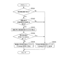
次に、制駆動力コントロールユニット8の処理について、図3を参照して説明する。
制駆動力コントロールユニット8の処理は、例えば10msec毎の所定サンプリング時間ΔT毎にタイマ割込によって実行する。なお、この図3に示す処理内には通信処理を設けていないが、演算処理によって取得した情報は、随時、記憶装置に更新して記憶すると共に、必要な情報を随時、記憶装置から読み出す。
Next, processing of the braking / driving
The processing of the braking / driving
まず、ステップS10において、上記各センサやコントローラ、コントロールユニットから各種データを読み込む。具体的には、各センサが検出した、各車輪速度Vwi、操舵角δ、マスタシリンダ液圧Pm及び方向スイッチ信号を取得する。
次に、ステップS20にて、車速Vを算出する。すなわち、車速Vを、下記(1)式のように車輪速度Vwiに基づいて算出する。
V=(Vwrl+Vwrr)/2 (:前輪駆動の場合)
V=(Vwfl+Vwfr)/2 (:後輪駆動の場合)
・・・(1)
First, in step S10, various data are read from each sensor, controller, or control unit. Specifically, each wheel speed Vwi, steering angle δ, master cylinder hydraulic pressure Pm, and direction switch signal detected by each sensor are acquired.
Next, the vehicle speed V is calculated in step S20. That is, the vehicle speed V is calculated based on the wheel speed Vwi as in the following formula (1).
V = (Vwr1 + Vwrr) / 2 (: front wheel drive)
V = (Vwfl + Vwfr) / 2 (: In the case of rear wheel drive)
... (1)
ここで、Vwfl、Vwfrは左右前輪それぞれの車輪速度である。Vwrl、Vwrrは左右後輪それぞれの車輪速度である。すなわち、上記(1)式では、車速Vを、従動輪の車輪速の平均値として算出している。なお、本実施形態では、後輪駆動の車両であるので、後者の式、すなわち前輪の車輪速度により車速Vを算出する。
また、ABS(Anti−lock Brake System)制御などの別の自動制動制御装置が作動している場合には、その別の制動制御装置で推定している推定車体速度を取得して、上記車速Vとして用いる。
Here, Vwfl and Vwfr are the wheel speeds of the left and right front wheels, respectively. Vwrl and Vwrr are the wheel speeds of the left and right rear wheels, respectively. That is, in the above equation (1), the vehicle speed V is calculated as an average value of the wheel speeds of the driven wheels. In this embodiment, since the vehicle is a rear-wheel drive vehicle, the vehicle speed V is calculated from the latter equation, that is, the wheel speed of the front wheels.
Further, when another automatic braking control device such as ABS (Anti-lock Break System) control is operating, an estimated vehicle speed estimated by the other braking control device is acquired, and the vehicle speed V Used as
次に、ステップS30では、左右の各レーダー装置24L/Rからの信号に基づき、自車両MMの左右側方について、障害物SMの存在Lobst・Robstの有無を取得する。なお、より検出精度の高いセンサを使用する場合には、自車両MMに対する側方障害物SMの相対位置及び相対速度も取得する。ここで、図4に示すように、自車両MM側方とは、自車両MMに対して斜め後方位置も含む。
Next, in step S30, the presence / absence of the presence SMobs / Robsts of the obstacles SM is acquired on the left and right sides of the host vehicle MM based on the signals from the left and
次に、ステップS35で、運転者の障害物SMと反対側の隣接車線への車線変更の意思を検出するための、車線変更意思検出処理を行う。
車線変更意思検出処理が実行されると、図5に示すように、まず、ステップS3501で、障害物SMの存在Lobst・Robstの有無を判定する。そして、障害物が左右共に存在しないと判定した場合には、ステップS3505に移行する。一方、左右の少なくとも一方に障害物SMが存在する場合には、ステップS3502に移行する。
Next, in step S35, lane change intention detection processing is performed to detect the driver's intention to change lanes to the adjacent lane opposite to the obstacle SM.
When the lane change intention detection process is executed, as shown in FIG. 5, first, in step S3501, the presence / absence of the obstruction SM presence Lobst / Robst is determined. If it is determined that there are no obstacles on the left and right, the process proceeds to step S3505. On the other hand, if there is an obstacle SM on at least one of the left and right, the process proceeds to step S3502.
ステップS3502では、運転者の隣接車線への車線変更の意思の検出の有無を判定する。本実施形態では、方向指示スイッチ20からの信号に基づき、運転者の車線変更の意思及びその方向を検出する。そして、方向指示器による方向指示操作がない場合には、運転者の車線変更の意思を検出しないと判定する。そして、運転者の車線変更の意思を検出しないと判定した場合には、ステップS3505に移行する。
一方、方向指示器による方向指示操作がある場合には、運転者の車線変更の意思を検出したと判定する。そして、運転者の車線変更の意思を検出したと判定した場合には、ステップS3503に移行する。
ステップS3503では、方向指示スイッチ20からの信号に基づき、運転者の車線変更の方向を検出して、ステップS3504に移行する。
In step S3502, the presence / absence of detection of the driver's intention to change lanes to the adjacent lane is determined. In the present embodiment, the driver's intention to change the lane and its direction are detected based on the signal from the
On the other hand, when there is a direction instruction operation by the direction indicator, it is determined that the driver's intention to change lanes has been detected. If it is determined that the driver's intention to change lanes has been detected, the process proceeds to step S3503.
In step S3503, the direction of the driver's lane change is detected based on the signal from the
ステップS3504では、ステップS3503で検出した運転者の車線変更の方向が障害物SMが存在する方向と同一であるか否かを判定する。そして、運転者の車線変更の方向が障害物SMが存在する方向と同一である場合には、ステップS3505に移行する。一方、運転者の車線変更の方向が障害物SMが存在する方向と反対側である場合には、運転者の障害物SMと反対側の隣接車線への車線変更の意思を検出したと判定して、ステップS3506に移行する。
ステップS3505では、車線変更意思検出フラグFchangeをOFFに設定し、一連の処理を終了する。
ステップS3506では、車線変更意思検出フラグFchangeをONに設定し、一連の処理を終了する。
そして、車線変更意思検出手段8Bbは、運転者の障害物SMと反対側の隣接車線への車線変更の意思を検出してからの継続時間をカウントする。
In step S3504, it is determined whether the direction of the driver's lane change detected in step S3503 is the same as the direction in which the obstacle SM exists. If the direction of the driver's lane change is the same as the direction in which the obstacle SM exists, the process proceeds to step S3505. On the other hand, when the driver's lane change direction is opposite to the direction in which the obstacle SM exists, it is determined that the driver's intention to change lanes to the adjacent lane opposite to the obstacle SM is detected. Then, the process proceeds to step S3506.
In step S3505, the lane change intention detection flag Fchange is set to OFF, and a series of processing ends.
In step S3506, the lane change intention detection flag Fchange is set to ON, and a series of processing ends.
Then, the lane change intention detection means 8Bb counts the continuation time after detecting the driver's intention to change the lane to the adjacent lane opposite to the obstacle SM.
次に、ステップS40では、撮像部13から、現在走行している走行路における自車両MMの横変位Xfront、及び走行車線の曲率βfrontを読み込む。
ただし、走行車線の曲率βfrontの取得は、撮像部13に限定しない。例えば、ナビゲーションシステム40の自車位置において記録している曲率情報などによって取得してもよい。
また、現在走行している走行路に対する自車両MMのヨー角φfrontを算出する。このヨー角φfrontは、レーン内の走行状況を検出するために使用する。
Next, in step S40, the lateral displacement Xfront of the host vehicle MM and the curvature βfront of the traveling lane on the currently traveling road are read from the
However, the acquisition of the curvature βfront of the traveling lane is not limited to the
Further, the yaw angle φfront of the host vehicle MM with respect to the currently traveling road is calculated. This yaw angle φfront is used to detect the running situation in the lane.
本実施形態では、このヨー角φfrontは、撮像部13による実測値を使用する。
ただし、撮像部13が撮像した近傍の車線区分線に基づいて、ヨー角φfrontを算出してもよい。この場合には、例えば、自車両MMの横変位Xfrontの変化量dXを用いて、下記(2)式によりヨー角φfrontを算出する。
φfront=tan-1(dX′/V(=dX/dY)) ・・・(2)
ここで、
dX :横変位Xfrontの単位時間当たりの変化量
dY :単位時間当たりの進行方向の変化量
dX′:上記変化量dXの微分値
である。
また、近傍の車線区分線に基づいてヨー角φfrontを算出する場合、上記(2)式のように、横変位Xfrontを用いてヨー角φfrontを算出することに限定しない。例えば、近傍で検出した車線区分線を遠方に延長して、その延長した車線区分線に基づいて、ヨー角φfrontを算出してもよい。
In the present embodiment, the yaw angle φfront uses a measured value obtained by the
However, the yaw angle φfront may be calculated based on the nearby lane markings imaged by the
φfront = tan −1 (dX ′ / V (= dX / dY)) (2)
here,
dX: change amount per unit time of lateral displacement Xfront dY: change amount in the traveling direction per unit time dX ′: differential value of the change amount dX.
In addition, when calculating the yaw angle φfront based on a nearby lane marking, it is not limited to calculating the yaw angle φfront using the lateral displacement Xfront as in the above equation (2). For example, a lane marking detected in the vicinity may be extended far and the yaw angle φfront may be calculated based on the extended lane marking.
次に、ステップS50では、中立ヨーレートφ’pathを算出する。
すなわち、中立ヨーレートφ’pathを、下記(3)式によって算出する。
φ’path=βfront×V ・・・(3)
この中立ヨーレートφ’pathは、自車両MMが走行路に沿った走行を維持するために必要なヨーレートである。中立ヨーレートφ’pathは、直進路を走行中はゼロとなる。しかし、カーブ路ではその曲率βfrontによって、中立ヨーレートφ’pathが変化する。したがって、この中立ヨーレートφ’pathを算出する際に、上記走行車線の曲率βfrontを用いる。
なお、この走行経路を維持するための中立ヨーレートφ’pathは、所定の間の時間のヨーレートφ’の平均値φ’aveを用いたり、あるいは時定数の大きいフィルタをヨーレートφ’に掛けたりした値を簡易的に算出してもよい。
Next, in step S50, a neutral yaw rate φ′path is calculated.
That is, the neutral yaw rate φ′path is calculated by the following equation (3).
φ'path = βfront × V (3)
The neutral yaw rate φ′path is a yaw rate necessary for the host vehicle MM to maintain traveling along the traveling path. The neutral yaw rate φ'path is zero when traveling on a straight road. However, on the curved road, the neutral yaw rate φ′path changes depending on the curvature βfront. Therefore, the curvature βfront of the travel lane is used when calculating the neutral yaw rate φ′path.
As the neutral yaw rate φ'path for maintaining this travel route, the average value φ'ave of the yaw rate φ 'during a predetermined time is used, or a filter with a large time constant is applied to the yaw rate φ'. The value may be simply calculated.
次に、ステップS60において、前方注視時間Tt(=車頭距離)を設定する。
前方注視時間Ttは、運転者の将来の障害物SMとの接触状況を予測するための閾値を決定づけるための時間である。例えば、前方注視時間Ttを1秒に設定しておく。
また、目標ヨーレートΨdriver及びΨdriverhoseiを算出する。
目標ヨーレートΨdriverは、下記式のように、操舵角δと車速度Vから算出する。この目標ヨーレートΨdriverは、操舵に応じて発生する目標のヨーレートである。Kvはゲインである。
Ψdriver = Kv・δ・V
Next, in step S60, a forward gaze time Tt (= vehicle head distance) is set.
The forward gaze time Tt is a time for determining a threshold value for predicting the contact situation of the driver with the future obstacle SM. For example, the forward gaze time Tt is set to 1 second.
Further, target yaw rates ψdriver and ψdriverhosei are calculated.
The target yaw rate ψdriver is calculated from the steering angle δ and the vehicle speed V as in the following equation. This target yaw rate ψdriver is a target yaw rate generated according to steering. Kv is a gain.
Ψdriver = Kv ・ δ ・ V
さらに、目標ヨーレートΨdriverhoseiを、下記(4)式によって算出する。この目標ヨーレートΨdriverhoseiは、目標ヨーレートΨdriverから、走行路を走行するために必要となるヨーレートφ’pathを除いた値である。これによって、カーブ路を走行するための操舵による影響を除去する。
Ψdriverhosei= Ψdriver − φ’path ・・・(4)
Further, the target yaw rate ψdriverhosei is calculated by the following equation (4). This target yaw rate Ψ driverhosei is a value obtained by removing the yaw rate φ′path necessary for traveling on the traveling path from the target yaw rate Ψ driver. This eliminates the influence of steering for traveling on a curved road.
Ψdriverhosei = Ψdriver − φ'path (4)
次に、ステップS65で、前方注視時間Ttを調整する。
前方注視時間Ttの調整処理を、車線変更意思検出フラグFchangeに応じて区分する。
「車線変更意思検出フラグFchange=OFFの場合(ステップS3505)」
車線変更意思検出フラグFchangeに基づき、運転者の障害物SMと反対側の隣接車線への車線変更の意思を検出しないと判定した場合には、そのままステップS70に移行する。
Next, in step S65, the forward gaze time Tt is adjusted.
The adjustment process of the forward gaze time Tt is classified according to the lane change intention detection flag Fchange.
“When the lane change intention detection flag Fchange = OFF (step S3505)”
If it is determined based on the lane change intention detection flag Fchange that the driver does not intend to change the lane to the adjacent lane opposite to the obstacle SM, the process proceeds to step S70 as it is.
「車線変更意思検出フラグFchange=ONの場合(ステップS3506)」
一方、車線変更意思検出フラグFchangeに基づき、運転者の障害物SMと反対側の隣接車線への車線変更の意思を検出したと判定した場合には、調整ゲインKt(Kt<1)を前方注視時間Ttに乗算することによって前方注視時間Ttを短くする方向に調整し、障害物への接近を防止する制御を抑制する。調整ゲインKtは、図6のようなマップに基づき設定してもよい。すなわち、調整ゲインKtを、運転者の障害物SMと反対側の隣接車線への車線変更の意思を検出してからの継続時間に応じて小さく設定する。図6のマップでは、調整ゲインKtは、運転者の障害物SMと反対側の隣接車線への車線変更の意思を検出してからの継続時間が所定時間となる前は所定値(1未満の所定値)である。そして、運転者の障害物SMと反対側の隣接車線への車線変更の意思を検出してからの継続時間が所定時間となった後は、該経過時間が長いほど小さな値となる。
“When the lane change intention detection flag Fchange = ON (step S3506)”
On the other hand, if it is determined that the driver's intention to change the lane to the adjacent lane opposite to the obstacle SM is detected based on the lane change intention detection flag Fchange, the adjustment gain Kt (Kt <1) is watched forward. By multiplying the time Tt, the forward gaze time Tt is adjusted to be shortened, and the control for preventing the approach to the obstacle is suppressed. The adjustment gain Kt may be set based on a map as shown in FIG. That is, the adjustment gain Kt is set to be small in accordance with the duration time after the driver's intention to change to the adjacent lane opposite to the obstacle SM is detected. In the map of FIG. 6, the adjustment gain Kt is a predetermined value (less than 1) before the continuation time after the driver's intention to change the lane to the adjacent lane opposite to the obstacle SM reaches a predetermined time. Predetermined value). And after the continuation time after detecting the driver's intention to change the lane to the adjacent lane opposite to the obstacle SM becomes a predetermined time, the longer the elapsed time, the smaller the value.
また、調整ゲインKtは、図7のように、走行車線の幅が狭くなるほど小さく設定してもよい。図7のマップでは、調整ゲインKtは、走行車線の幅が所定値より広い場合は所定値である。そして、走行車線の幅が所定値より狭い場合には、走行車線の幅が狭いほど小さな値となる。
そして、下記式によって、前方注視時間Ttを調整する。そして、ステップS70に移行する。
Tt ← Tt×Kt
ここで、前方注視時間Ttは、左右の車線区分線毎に個別に調整しておく。そして、左右の障害物に応じて、隣接する車線区分線に対応する前方注視時間Ttを使用する。
Further, as shown in FIG. 7, the adjustment gain Kt may be set smaller as the width of the travel lane becomes smaller. In the map of FIG. 7, the adjustment gain Kt is a predetermined value when the width of the travel lane is wider than a predetermined value. And when the width of a traveling lane is narrower than a predetermined value, it becomes a small value, so that the width of a traveling lane is narrow.
Then, the forward gaze time Tt is adjusted by the following formula. Then, the process proceeds to step S70.
Tt ← Tt x Kt
Here, the forward gaze time Tt is individually adjusted for each of the left and right lane markings. And according to the left and right obstacles, the forward gaze time Tt corresponding to the adjacent lane marking is used.
なお、もちろん調整ゲインKtは、運転者の障害物SMと反対側の隣接車線への車線変更の意思を検出してからの継続時間に応じて小さく設定するとともに、走行車線の幅が狭くなるほど小さく設定してもよい。この場合は、調整ゲインKtに、運転者の障害物SMと反対側の隣接車線への車線変更の意思を検出してからの継続時間に応じて小さくなる1未満のゲインを乗算するとともに、走行車線の幅が狭くなるほど小さくなる1以下のゲインを乗算して、調整ゲインKtを補正すればよい。 Of course, the adjustment gain Kt is set to be small according to the duration after the driver's intention to change to the adjacent lane on the opposite side of the obstacle SM, and becomes smaller as the width of the traveling lane becomes narrower. It may be set. In this case, the adjustment gain Kt is multiplied by a gain of less than 1 that becomes smaller according to the duration after the driver's intention to change to the adjacent lane on the opposite side of the obstacle SM, and travel The adjustment gain Kt may be corrected by multiplying a gain of 1 or less, which decreases as the lane width decreases.
次に、ステップS70では、下記(5)式に基づき、現在の走行路位置に対する横方向の自車両予測位置ΔXbを算出する。この自車両予測位置ΔXbは、走行路を離脱して車線変更を行うか否かの判定に使用する。すなわち、自車両予測位置ΔXbは、障害物SMに対する回避の支援制御を開始するかどうかに使用する。実際には、この自車両予測位置ΔXbも、左右個別に求める。
ΔXb =(K1φ+K2φm+K3φm’) ・・・(5)
ここで、
φ :ヨー角
φm :目標ヨー角速度
φm’:目標ヨー角加速度
である。
Next, in step S70, the predicted vehicle position ΔXb in the lateral direction with respect to the current travel path position is calculated based on the following equation (5). This own vehicle predicted position ΔXb is used to determine whether or not to change the lane after leaving the travel path. That is, the host vehicle predicted position ΔXb is used for starting avoidance support control for the obstacle SM. Actually, the own vehicle predicted position ΔXb is also obtained separately on the left and right.
ΔXb = (K1φ + K2φm + K3φm ′) (5)
here,
φ: Yaw angle φm: Target yaw angular velocity φm ': Target yaw angular acceleration.
また、上記目標ヨー角速度φmは、下記式となる。
φm =Ψdriverhosei×Tt
目標ヨー角加速度φm’は、下記式となる。
φm’= φm×Tt2
ここで、自車両予測位置ΔXbを、ヨー角の次元とするために、前方注視距離Lを用いると、下式で表すことができる。
ΔXb=L・(k1φ+k2φm×T+k3φm’×Tt2)
ここで、前方注視距離Lと前方注視時間Ttとは、下記式の関係にある。
前方注視距離L=前方注視時間Tt×車速V
The target yaw angular velocity φm is expressed by the following equation.
φm = Ψdriverhosei × Tt
The target yaw angular acceleration φm ′ is expressed by the following formula.
φm ′ = φm × Tt 2
Here, when the forward gaze distance L is used in order to set the vehicle predicted position ΔXb to the dimension of the yaw angle, it can be expressed by the following equation.
ΔXb = L · (k1φ + k2φm × T + k3φm ′ × Tt 2 )
Here, the front gaze distance L and the front gaze time Tt are in the relationship of the following formula.
Forward gaze distance L = front gaze time Tt × vehicle speed V
こうした特性をふまえると、設定ゲインK1は車速を関数とした値となる。また、設定ゲインK2は、車速と前方注視時間を関数とした値となる。設定ゲインK3は、車速と、前方注視時間の2乗を関数とした値となる。
なお、自車両MMの予測位置を、下記式のように、操舵角成分と操舵速度成分を個別に求めてセレクトハイによって算出してもよい。
ΔXb= max(K2φm、K3∫φm’)
Considering these characteristics, the set gain K1 is a value that is a function of the vehicle speed. The set gain K2 is a value that is a function of the vehicle speed and the forward gaze time. The set gain K3 is a value that is a function of the vehicle speed and the square of the forward gaze time.
Note that the predicted position of the host vehicle MM may be calculated by selecting high by separately obtaining the steering angle component and the steering speed component as in the following equation.
ΔXb = max (K2φm, K3∫φm ′)
次に、ステップS80では、制御開始のための判定閾値を設定する。この判定閾値は、側方障害物SMに対する回避制御を開始するかどうかの判定閾値となる。
本実施形態では、レーダー装置24L/Rにより、自車両MMと障害物SMとの横方向相対距離ΔOを検出する。そして、その横方向相対距離ΔOを上記判定閾値として設定する(図4参照)。
Next, in step S80, a determination threshold for starting control is set. This determination threshold value is a determination threshold value for determining whether to start avoidance control for the side obstacle SM.
In the present embodiment, the lateral relative distance ΔO between the host vehicle MM and the obstacle SM is detected by the
また、自車両MMと障害物SMとの横方向相対距離ΔOを正確に求めることができない場合には、障害物距離X2obstを上記判定閾値として設定する(図4参照)。障害物距離X2obstは、仮想的に障害物SMが存在するものとして予め設定された所定値である。すなわち、車線区分線から外側に変位した障害物距離X2obstに、障害物SMが存在するものとして処理することとなる。なお、障害物距離X2obstを設定する車線区分線からの変位量を「0」としてもよい。この場合には、車線区分線と障害物距離X2obstとが同位置となる。 Further, when the lateral relative distance ΔO between the host vehicle MM and the obstacle SM cannot be obtained accurately, the obstacle distance X2obst is set as the determination threshold (see FIG. 4). The obstacle distance X2obst is a predetermined value set in advance assuming that the obstacle SM exists virtually. That is, processing is performed assuming that the obstacle SM exists at the obstacle distance X2obst displaced outward from the lane marking. The displacement amount from the lane marking that sets the obstacle distance X2obst may be set to “0”. In this case, the lane line and the obstacle distance X2obst are at the same position.
ここで、走行路に沿った方向にY軸をとり、走行路と垂直方向つまり車線幅方向にX軸を取ったX−Y座標系を使用する。そして、X軸座標上で障害物SMの横位置を検出する。この横位置に基づき、上記横方向相対距離ΔOを求める。
なおここで、障害物SMを検出するかどうかとして設定する障害物検出範囲は、自車両MMの側方における、所定の縦・横位置となるように設定する。また縦位置については、障害物SMが自車両MMに対して接近する相対速度が大きければ大きいほど、障害物検出範囲が広くなるように設定してもよい。
Here, an XY coordinate system is used in which the Y axis is taken in the direction along the road and the X axis is taken in the direction perpendicular to the road, that is, in the lane width direction. Then, the lateral position of the obstacle SM is detected on the X-axis coordinates. Based on the lateral position, the lateral relative distance ΔO is obtained.
Here, the obstacle detection range set as whether or not the obstacle SM is detected is set to be a predetermined vertical / horizontal position on the side of the host vehicle MM. The vertical position may be set so that the obstacle detection range becomes wider as the relative speed at which the obstacle SM approaches the host vehicle MM increases.
次に、ステップS90にて、制御開始の判定を実施する。
まず、障害物SMの存在Lobst・Robstの有無を判定する。障害物が左右共に存在しない場合には、障害物回避制御判断フラグFout_obstをOFFに設定する。そして、ステップS100に移行する。
一方、左右の少なくとも一方に障害物SMが存在する場合には、障害物が存在する車線区分線側について、下記式を満足する場合に、制御開始と判定する。
Next, in step S90, control start determination is performed.
First, it is determined whether or not the obstacle SM exists. If there are no obstacles on the left and right, the obstacle avoidance control determination flag Fout_obst is set to OFF. Then, the process proceeds to step S100.
On the other hand, when the obstacle SM exists on at least one of the left and right sides, it is determined that the control is started when the following equation is satisfied for the lane marking line side where the obstacle exists.
すなわち、図4に示すように、自車両MMの将来予測位置ΔXbが検出障害物SMとの距離ΔOとなった場合に、つまり下記式を満足する場合に、障害物SMに対するリスク度合いが高くなったと判断する。
ΔXb ≧ ΔO
ただし、自車両MMと検出障害物SMとの正確な距離ΔOを求めることができない場合には、次のように判定してもよい。
ΔX2=ΔXb−ΔX0 ≧ X2obst
ΔX0は、自車両と車線区分線との間の横距離である。
That is, as shown in FIG. 4, when the future predicted position ΔXb of the host vehicle MM becomes the distance ΔO with the detected obstacle SM, that is, when the following expression is satisfied, the degree of risk for the obstacle SM increases. Judge that
ΔXb ≧ ΔO
However, when the accurate distance ΔO between the host vehicle MM and the detected obstacle SM cannot be obtained, the following determination may be made.
ΔX2 = ΔXb−ΔX0 ≧ X2obst
ΔX0 is the lateral distance between the host vehicle and the lane marking.
すなわち、図4に示すように、車線区分線に対する自車両MMの将来予測位置の横位置ΔX2が、障害物距離ΔX2obst以上となったか否かを判定する。そして、上記条件を満足した場合に、障害物SMに対するリスク度合いが高くなったとして、障害物SMに対する制御開始と判定する。障害物SMに対する制御開始と判定した場合には、障害物回避制御Fout_obstをONに設定する。上記条件を満足しない、すなわち、車線区分線と自車両MMの将来予測位置との横位置ΔX2が判定閾値未満の場合には、障害物回避制御判断フラグFout_obstをOFFに設定する。 That is, as shown in FIG. 4, it is determined whether or not the lateral position ΔX2 of the future predicted position of the host vehicle MM with respect to the lane marking is equal to or greater than the obstacle distance ΔX2obst. And when the said conditions are satisfied, it determines with the control start with respect to the obstacle SM being judged that the risk degree with respect to the obstacle SM became high. When it is determined that the control for the obstacle SM is started, the obstacle avoidance control Fout_obst is set to ON. When the above condition is not satisfied, that is, when the lateral position ΔX2 between the lane marking and the future predicted position of the host vehicle MM is less than the determination threshold, the obstacle avoidance control determination flag Fout_obst is set to OFF.
なお、この将来予測位置ΔXbは、実際には、車両の左側及び右側のそれぞれについてΔXbL/ΔXbRとして求めて、個別に判定を行う。
また、ここで対象とする障害物SMは、自車両MMの後側方向の車両に対して設定するだけでなく、隣接車線前方の対向車両に対しても制御対象としてもよい。
ここで、将来予測位置ΔXbが判定閾値未満か判定する場合に、ΔXb ≧ ΔO−F、ΔX2 ≧ X2obst−FのようにしてF分のヒスをもたせてもよい。すなわち、不感帯を設定してもよい。すなわち、制御介入閾値と制御終了閾値との間に不感帯を設けてもよい。
Note that the future predicted position ΔXb is actually determined as ΔXbL / ΔXbR for each of the left side and the right side of the vehicle and is individually determined.
Further, the target obstacle SM here is not only set for the vehicle in the rear direction of the host vehicle MM, but may also be a control target for the oncoming vehicle in front of the adjacent lane.
Here, when it is determined whether or not the future predicted position ΔXb is less than the determination threshold, a hysteresis of F may be provided as ΔXb ≧ ΔO−F and ΔX2 ≧ X2obst−F. That is, a dead zone may be set. That is, a dead zone may be provided between the control intervention threshold and the control end threshold.
また、Fout_obstをONに設定可能なのは、Fout_obstがOFFとなっている場合とする。また、Fout_obstをONに設定可能とする条件として、Fout_obstをOFFと設定した後所定時間経過した後とするなど、時間的な条件を加えてもよい。また、Fout_obstをONと判定してから所定時間Tcontrolが経過したら、Fout_obst=OFFとし制御を終了してもよい。 Also, Fout_obst can be set to ON when Fout_obst is OFF. Further, as a condition for enabling Fout_obst to be set to ON, a temporal condition may be added, for example, after a predetermined time has elapsed after Fout_obst is set to OFF. Further, when a predetermined time Tcontrol has elapsed since Fout_obst is determined to be ON, the control may be terminated by setting Fout_obst = OFF.
さらに、障害物回避制御の実施中においては、将来予測位置の判定方向によって、制御の実施方向Dout_obstを判定する。将来予測位置が左になった場合には、Dout_obst=LEFTとし、右になった場合にはDout_obst=RIGHTと設定する。
ここで、アンチスキッド制御(ABS)、トラクション制御(TCS)又はビークルダイナミックスコントロール装置(VDC)が作動している場合には、障害物回避制御判断フラグFout_obstをOFFに設定する。これは、自動制動制御が作動中は、障害物回避制御を作動しないようにするためである。
Further, during the execution of the obstacle avoidance control, the control execution direction Dout_obst is determined based on the determination direction of the future predicted position. If the future predicted position is on the left, Dout_obst = LEFT is set, and if it is on the right, Dout_obst = RIGHT is set.
Here, when the anti-skid control (ABS), the traction control (TCS), or the vehicle dynamics control device (VDC) is operating, the obstacle avoidance control determination flag Fout_obst is set to OFF. This is to prevent the obstacle avoidance control from being activated while the automatic braking control is in operation.
なおこうした判定方法は、障害物SM方向へのヨー角φ、操舵角δ、操舵速度δ’それぞれに対して閾値を設定し、それらの閾値を障害物SMに接近すればするほど制御開始タイミングの判定がしづらくなるように設定することと同義となる。目標ヨーレートφm’は一般的に広く使用する公式のとおり操舵角と車速の関係によって求まるものだからである。 In this determination method, threshold values are set for each of the yaw angle φ, the steering angle δ, and the steering speed δ ′ in the direction of the obstacle SM, and the closer the threshold is to the obstacle SM, the more the control start timing becomes. This is synonymous with setting so that the determination is difficult. This is because the target yaw rate φm ′ is determined by the relationship between the steering angle and the vehicle speed, as in a widely used formula.
次に、ステップS100では、警報発生の処理を行う。
ここでは、ステップS90にて制御開始の位置に到達したと判定と判定した場合には、警報を発生する。
なお警報は、上述の前方注視時間に基づく前方注視点(自車両MMの将来予測位置)が制御開始の位置に到達する前に発生するようにしてもよい。例えば、ステップS90での検出に用いている前方注視時間Ttよりも長くなるように、所定のゲインKbuzz(Kbuzz>1)を掛ける。そして、(Tt×Kbuzz)を使用して(5)式に基づき算出した前方注視点が、ステップS90での制御開始の位置に到達したと判断したときに警報を発生する。またステップS90において障害物回避システムの作動を開始すると判定して警報を発生し、それから所定の時間経過の後に、制御を開始するようにしてもよい。
Next, in step S100, an alarm generation process is performed.
Here, if it is determined in step S90 that the control start position has been reached, an alarm is generated.
Note that the alarm may be generated before the forward gazing point (the future predicted position of the host vehicle MM) based on the above-mentioned forward gazing time reaches the control start position. For example, a predetermined gain Kbuzz (Kbuzz> 1) is applied so as to be longer than the forward gaze time Tt used for the detection in step S90. Then, an alarm is generated when it is determined that the forward gazing point calculated based on Equation (5) using (Tt × Kbuzz) has reached the control start position in step S90. Further, in step S90, it may be determined that the operation of the obstacle avoidance system is started, an alarm is generated, and then control is started after a predetermined time has elapsed.
次に、ステップS110にて、目標ヨーモーメントMsを設定する。
障害物回避制御判断フラグFout_obstがONの場合には、下記のように目標ヨーモーメントMsを算出する。障害物回避制御判断フラグFout_obstがOFFの場合には、目標ヨーモーメントMsを0に設定して、次のステップS120に移行する。
すなわち、障害物回避制御判断フラグFout_obstがONの場合に、目標ヨーモーメントMsを、下記式によって求める。
Ms=K1recv×K2recv×ΔXs ・・・(6)
ΔXs =(K1mom・φ+K2mom・φm)
Next, in step S110, a target yaw moment Ms is set.
When the obstacle avoidance control determination flag Fout_obst is ON, the target yaw moment Ms is calculated as follows. When the obstacle avoidance control determination flag Fout_obst is OFF, the target yaw moment Ms is set to 0, and the process proceeds to the next step S120.
That is, when the obstacle avoidance control determination flag Fout_obst is ON, the target yaw moment Ms is obtained by the following equation.
Ms = K1recv × K2recv × ΔXs (6)
ΔXs = (K1mom · φ + K2mom · φm)
ここで、K1recvは車両諸元から決まる比例ゲイン(ヨー慣性モーメント)である。K2recvは車速Vに応じて変動するゲインである。ゲインK2recvの例を、図8に示す。図8に示すように、例えばゲインK2recvは、低速域で大きい値になり、車速Vがある値になると、車速Vと反比例の関係となり、その後ある車速Vに達すると小さい値で一定値となる。また設定ゲインK1momは車速を関数とした値となる。また、設定ゲインK2momは、車速と前方注視時間を関数とした値となる。 Here, K1recv is a proportional gain (yaw inertia moment) determined from vehicle specifications. K2recv is a gain that varies according to the vehicle speed V. An example of the gain K2recv is shown in FIG. As shown in FIG. 8, for example, the gain K2recv becomes a large value in the low speed range, and when the vehicle speed V becomes a certain value, it has an inversely proportional relationship with the vehicle speed V, and thereafter becomes a constant value with a small value when reaching a certain vehicle speed V. . The set gain K1mom is a value that is a function of the vehicle speed. The set gain K2mom is a value that is a function of the vehicle speed and the forward gaze time.
この(6)式によれば、白線とのヨー角度φや運転者が切り増しをしたステアリングによって定常的に発生するヨーレートが大きくなるほど、目標ヨーモーメントMsは大きくなる。
あるいは、目標ヨーモーメントMsを、下記(7)式から算出してもよい。この(7)式は、(6)式に対して、ゲインK3(=1/Tt2)を掛けることと同義である。このゲインK3は、前方注視時間Ttが大きくなるほど減少するゲインとなる。
Ms= K1recv×ΔXb/(L×Tt2) ・・・(7)
According to the equation (6), the target yaw moment Ms increases as the yaw angle φ with respect to the white line or the yaw rate that is constantly generated by the steering increased by the driver increases.
Alternatively, the target yaw moment Ms may be calculated from the following equation (7). This equation (7) is synonymous with multiplying equation (6) by a gain K3 (= 1 / Tt 2 ). The gain K3 is a gain that decreases as the forward gaze time Tt increases.
Ms = K1recv × ΔXb / (L × Tt 2 ) (7)
どの程度の制御時間Tをかけてヨー角を制御するかを示す上記(7)式を使用すると、次のようになる。すなわち、制御時間Tと前方注視時間Ttとが一致するように設定することで、前方注視時間Ttが短くなった際には、車両を戻すための時間Tが短くなる。この結果として制御量が強くなる。すなわち、制御開始タイミングが遅くなるようにしても、制御開始する際の制御量は大きくなる。また、制御開始タイミングが早くなるようにした際には制御量は小さくなる。この結果、運転者に対しては前方注視点の設定によらず、状況に沿った違和感の少ない制御を実施することが可能となる。 When the above equation (7) indicating how much control time T is taken to control the yaw angle is obtained as follows. That is, by setting the control time T and the forward gaze time Tt to coincide with each other, when the front gaze time Tt is shortened, the time T for returning the vehicle is shortened. As a result, the control amount becomes stronger. That is, even when the control start timing is delayed, the control amount at the start of the control increases. Further, when the control start timing is made earlier, the control amount becomes smaller. As a result, it is possible to perform control with less discomfort according to the situation, regardless of the setting of the forward gazing point for the driver.
なお、上記Fout_obstの判定は、操舵情報に基づいて将来の進路変更を予測するものである。
ここで、本制御の他に、車線逸脱防止制御を備える場合にあっては、本制御が作動開始するときと車線逸脱防止制御が作動開始するときとで、いずれかが先に制御を開始するかによって、先に制御開始した制御を優先し、その制御が終了するまで他方の制御を実施しないようにしてもよい。
Note that the determination of Fout_obst predicts a future course change based on the steering information.
Here, in the case where the lane departure prevention control is provided in addition to the main control, one of the control starts first when the main control starts to operate and when the lane departure prevention control starts. Depending on the situation, the control that has been started first may be given priority, and the other control may not be performed until the end of the control.
次に、ステップS120では、障害物回避のための目標ヨーモーメントMsを発生する指令を算出して、算出した指令を出力した後に、最初の処理に復帰する。
ここで、本実施形態では、障害物回避のためのヨーレートMsを発生するための手段として、制駆動力を用いてヨーモーメントを発生する場合の例を、以下に説明する。
なお、ヨーレートを発生する手段としてステアリング反力制御装置を用いる場合には、ステアリング反力FrstrはFrstr=K×Msとして反力を発生すればよい。
Next, in step S120, a command for generating the target yaw moment Ms for obstacle avoidance is calculated, and after the calculated command is output, the process returns to the first process.
Here, in the present embodiment, an example in which a yaw moment is generated using a braking / driving force as means for generating a yaw rate Ms for avoiding an obstacle will be described below.
When the steering reaction force control device is used as the means for generating the yaw rate, the steering reaction force Frstr may be generated as Frstr = K × Ms.
またヨーレートを発生する手段としてステアリング制御装置を用いる場合には、ステアリング角STRθはSTRθ=K×Ms’として求めた結果をステアリングに付与すればよい。
またヨーレートを発生する手段としてはステアリング制御装置を用い、その操舵力(操舵トルク)をSTRtrg=K×Msとして求めて発生してもよい。
When the steering control device is used as a means for generating the yaw rate, the steering angle STRθ may be given to the steering as a result obtained as STRθ = K × Ms ′.
Further, as a means for generating the yaw rate, a steering control device may be used, and the steering force (steering torque) may be calculated as STRtrg = K × Ms.
目標ヨーモーメントMsが0の場合、すなわちヨーモーメント制御を実施しない条件との判定結果を得た場合には、下記(8)式及び(9)式に示すように、各車輪の目標制動液圧Psi(i=fl、fr、rl、rr)を制動液圧Pmf、Pmrにする。
Psfl=Psfr=Pmf ・・・(8)
Psrl=Psrr=Pmr ・・・(9)
ここで、Pmfは前輪用の制動液圧である。また、Pmrは後輪用の制動液圧であり、前後配分を考慮して前輪用の制動液圧Pmfに基づいて算出した値になる。例えば、運転者がブレーキ操作をしていれば、制動液圧Pmf、Pmrはそのブレーキ操作の操作量(マスタシリンダ液圧Pm)に応じた値になる。
When the target yaw moment Ms is 0, that is, when the determination result that the yaw moment control is not performed is obtained, as shown in the following equations (8) and (9), the target brake hydraulic pressure of each wheel Psi (i = fl, fr, rl, rr) is set to the brake fluid pressures Pmf, Pmr.
Psfl = Psfr = Pmf (8)
Psrl = Psrr = Pmr (9)
Here, Pmf is the brake fluid pressure for the front wheels. Further, Pmr is the braking fluid pressure for the rear wheels, and is a value calculated based on the braking fluid pressure Pmf for the front wheels in consideration of the front-rear distribution. For example, if the driver is operating a brake, the brake fluid pressures Pmf and Pmr are values corresponding to the operation amount of the brake operation (master cylinder fluid pressure Pm).
一方、目標ヨーモーメントMsの絶対値が0より大きい場合、すなわち障害物回避制御を開始するとの判定結果を得た場合には、次のような処理を行う。
すなわち、目標ヨーモーメントMsに基づいて、前輪目標制動液圧差ΔPsf及び後輪目標制動液圧差ΔPsrを算出する。具体的には、下記(10)式及び(11)式により目標制動液圧差ΔPsf、ΔPsrを算出する。
ΔPsf=2・Kbf・(Ms×FRratio)/T ・・・(10)
ΔPsr=2・Kbr・(Ms×(1−FRratio))/T ・・・(11)
ここで、
FRratio:設定用閾値
T:トレッド
Kbf、Kbr:制動力を制動液圧に換算する場合の前輪及び後輪についての換算係数
である。
On the other hand, when the absolute value of the target yaw moment Ms is larger than 0, that is, when the determination result that the obstacle avoidance control is started is obtained, the following processing is performed.
That is, the front wheel target braking hydraulic pressure difference ΔPsf and the rear wheel target braking hydraulic pressure difference ΔPsr are calculated based on the target yaw moment Ms. Specifically, the target braking hydraulic pressure differences ΔPsf and ΔPsr are calculated by the following equations (10) and (11).
ΔPsf = 2 · Kbf · (Ms × FRratio) / T (10)
ΔPsr = 2 · Kbr · (Ms × (1−FR ratio)) / T (11)
here,
FRratio: threshold value for setting T: tread Kbf, Kbr: conversion factors for the front and rear wheels when the braking force is converted to the braking hydraulic pressure.
なお、上記トレッドTは、ここでは便宜上前後同じ値として扱う。また、Kbf、Kbrは、ブレーキ諸元により定まる。
このように、目標ヨーモーメントMsの大きさに応じて車輪で発生する制動力を配分する。つまり、各目標制動液圧差ΔPsf、ΔPsrに所定値を与え、前後それぞれの左右輪で制動力差を発生する。そして、算出した目標制動液圧差ΔPsf、ΔPsrを用いて、最終的な各車輪の目標制動液圧Psi(i=fl、fr、rl、rr)を算出する。
In addition, the said tread T is handled as the same value before and behind here for convenience. Kbf and Kbr are determined by the brake specifications.
Thus, the braking force generated at the wheel is distributed according to the magnitude of the target yaw moment Ms. That is, a predetermined value is given to each target braking hydraulic pressure difference ΔPsf, ΔPsr, and a braking force difference is generated between the left and right wheels respectively. Then, the final target brake fluid pressure Psi (i = fl, fr, rl, rr) of each wheel is calculated using the calculated target brake fluid pressure differences ΔPsf, ΔPsr.
具体的には、実施方向Dout_strがLEFTの場合、すなわち左側の障害物SMに対する障害物回避制御を実施する場合には、下記(12)式により各車輪の目標制動液圧Psi(i=fl、fr、rl、rr)を算出する。
Psfl=Pmf
Psfr=Pmf+ΔPsf
Psrl=Pmr
Psrr=Pmr+ΔPsr
・・・(12)
Specifically, when the execution direction Dout_str is LEFT, that is, when the obstacle avoidance control for the left obstacle SM is performed, the target braking hydraulic pressure Psi (i = fl, fr, rl, rr) is calculated.
Psfl = Pmf
Psfr = Pmf + ΔPsf
Psrl = Pmr
Psrr = Pmr + ΔPsr
(12)
また、実施方向DoutがRIGHTの場合、すなわち右側の車線区分線に対して車線逸脱傾向がある場合、下記(13)式により各車輪の目標制動液圧Psi(i=fl、fr、rl、rr)を算出する。
Psfl=Pmf+ΔPsf
Psfr=Pmf
Psrl=Pmr+ΔPsr
Psrr=Pmr
・・・(13)
Further, when the execution direction Dout is RIGHT, that is, when there is a tendency to deviate from the lane marking on the right side, the target braking hydraulic pressure Psi (i = fl, fr, rl, rr) of each wheel is calculated according to the following equation (13). ) Is calculated.
Psfl = Pmf + ΔPsf
Psfr = Pmf
Psrl = Pmr + ΔPsr
Psrr = Pmr
... (13)
この(12)式及び(13)式によれば、車線逸脱回避側の車輪の制動力が大きくなるように、左右輪の制駆動力差が発生する。
また、ここでは、(12)式及び(13)式が示すように、運転者によるブレーキ操作、すなわち制動液圧Pmf、Pmrを考慮して各車輪の目標制動液圧Psi(i=fl、fr、rl、rr)を算出している。
そして、制駆動力コントロールユニット8は、このようにして算出した各車輪の目標制動液圧Psi(i=fl、fr、rl、rr)を制動流体圧指令値として、制動流体圧制御部7に出力する。
According to the equations (12) and (13), the braking / driving force difference between the left and right wheels is generated so that the braking force of the wheels on the lane departure avoidance side is increased.
Further, here, as shown in the equations (12) and (13), the brake operation by the driver, that is, the target brake fluid pressure Psi (i = fl, fr) of each wheel in consideration of the brake fluid pressures Pmf, Pmr. , Rl, rr).
Then, the braking / driving
(動作・作用)
自車両の走行状態であるヨー角φ、ヨー角速度φm等に基づき、前方注視時間T後の自車両の将来位置として自車両予測位置ΔXbを求める。
そして、障害物SMを検出した側の自車両予測位置ΔXbが、自車両MMと検出障害物SMとの距離ΔO以上となると、障害物回避のための支援制御を開始する(図4参照)。支援制御開始と判定すると、自車両予測位置ΔXbに基づき、制御量として目標ヨーモーメントMsを算出し、その目標ヨーモーメントMsが発生するように制駆動力を制御する。これによって、障害物への接近を防止する方向に自車両を制御することとなる。
(Operation / Action)
Based on the yaw angle φ, yaw angular velocity φm, and the like, which are the traveling state of the host vehicle, the host vehicle predicted position ΔXb is obtained as the future position of the host vehicle after the forward gaze time T.
When the predicted vehicle position ΔXb on the side where the obstacle SM is detected is equal to or greater than the distance ΔO between the host vehicle MM and the detected obstacle SM, assistance control for avoiding the obstacle is started (see FIG. 4). When it is determined that the assist control is started, the target yaw moment Ms is calculated as a control amount based on the predicted vehicle position ΔXb, and the braking / driving force is controlled so that the target yaw moment Ms is generated. As a result, the host vehicle is controlled in a direction that prevents access to an obstacle.
ここで、図9に示すように、運転者は、隣接車線への車線変更を行う際に、車線変更を行う方向に操舵を行う前に、車線変更を行う方向とは逆の方向に操舵を行う予備動作を行う場合がある。なお、図9は、自車両MMの運転者が、下側の隣接車線への車線変更を行う場合を示している。また、図9では、予備動作による自車両MMの動きを、矢印線で示す。この場合、予備動作に応じて対して障害物回避のための支援制御が行われると、運転者に違和感を与える。 Here, as shown in FIG. 9, when changing the lane to the adjacent lane, the driver steers in the direction opposite to the direction in which the lane is changed before steering in the direction in which the lane is changed. There is a case where a preliminary operation is performed. FIG. 9 shows a case where the driver of the host vehicle MM changes the lane to the adjacent lower lane. Further, in FIG. 9, the movement of the host vehicle MM by the preliminary operation is indicated by an arrow line. In this case, when assistance control for obstacle avoidance is performed according to the preliminary movement, the driver feels uncomfortable.
そこで、障害物SMを検出した際に、運転者の障害物SMと反対側の隣接車線への車線変更の意思を検出した場合には、障害物への接近を防止する制御を抑制する。すなわち、前方注視時間Ttを短くする方向に調整する。また、目標ヨーモーメントMsを減じるように調整する。これによって、必要以上に制御が行われることを防止することで、運転者への違和感を低減できる。 Therefore, when the obstacle SM is detected, if the driver's intention to change the lane to the adjacent lane opposite to the obstacle SM is detected, the control for preventing the approach to the obstacle is suppressed. In other words, the forward gaze time Tt is adjusted to be shortened. Further, the target yaw moment Ms is adjusted to be reduced. Accordingly, it is possible to reduce discomfort to the driver by preventing the control from being performed more than necessary.
また、走行車線の幅が狭くなるほど、自車両と車線区分線との間の横距離ΔX0が小さくなるため、制御が開始されやすくなる。すなわち、必要以上に制御が開始される。そこで、走行車線の幅が狭くなることに応じて、前方注視時間Ttを短くする方向に調整する。つまり、前方注視点が現在の位置に近づいて、制御が開始し難くなる。すなわち、制御開始タイミングを遅らせることにより、制御の抑制の度合いが高くなるように調整する。これによって、必要以上に障害物回避制御が開始することを防止することで、運転者への違和感を低減できる。この場合、制御開始タイミングを遅らせるだけであるので、必要な側方障害物に対する支援制御は行う。 In addition, as the width of the traveling lane becomes narrower, the lateral distance ΔX0 between the host vehicle and the lane marking becomes smaller, so that the control is easily started. That is, control is started more than necessary. Therefore, the forward gaze time Tt is adjusted to be shortened in accordance with the narrowing of the travel lane. That is, the forward gazing point approaches the current position, and control becomes difficult to start. That is, by adjusting the control start timing, adjustment is performed so that the degree of control suppression is increased. Accordingly, it is possible to reduce a sense of discomfort to the driver by preventing the obstacle avoidance control from starting more than necessary. In this case, since only the control start timing is delayed, support control for necessary side obstacles is performed.
すなわち、運転者に違和感のある制御を低減しつつ、運転者が障害物SM方向への意図的に操舵した際の制御開始を可能となる。
ここで、レーダー装置24L/Rは障害物検出手段を構成する。将来位置予測手段8A(ステップS70)が将来位置予測手段を構成する。回避制御開始検出手段8B(ステップS80、S90)及び障害物回避制御手段8C(ステップS100〜S120)が障害物回避制御手段を構成する。車線変更意思検出手段8Bb(ステップS35)が車線変更意思検出手段を構成する。開始タイミング調整手段8Ba(ステップS65)が制御抑制手段を構成する。方向スイッチ20が方向スイッチを構成する。
That is, it is possible to start the control when the driver steers intentionally in the direction of the obstacle SM while reducing the control that is uncomfortable for the driver.
Here, the
(本実施形態の効果)
(1)障害物回避制御手段が、予測した自車両の将来位置に基づき障害物に対するリスク度合いを算出する。そして、その算出した障害物に対するリスク度合いに応じて、障害物への接近を防止するように自車両を制御する。このとき、制御抑制手段が、車線変更意思検出手段が運転者の障害物と反対側の隣接車線への車線変更の意思を検出したと判定した場合には、障害物への接近を防止する制御を抑制する。
すなわち、障害物を検出した際に、運転者の障害物の反対側の隣接車線への車線変更の意思を検出した場合には、障害物への接近を防止する制御を抑制する。
これによって、必要以上に制御が行われることを防止すると共に、必要な側方障害物に対する支援制御を行う。
したがって、運転者に違和感を与える制御を低減しつつ、側方障害物に対する支援制御を適切に行うことが可能となる。
(Effect of this embodiment)
(1) The obstacle avoidance control means calculates a risk degree for the obstacle based on the predicted future position of the host vehicle. Then, the host vehicle is controlled so as to prevent the approach to the obstacle according to the calculated risk level for the obstacle. At this time, if the control suppression means determines that the lane change intention detection means has detected the intention to change the lane to the adjacent lane on the opposite side of the driver's obstacle, the control for preventing access to the obstacle Suppress.
That is, when an obstacle is detected, if the driver's intention to change the lane to the adjacent lane on the opposite side of the obstacle is detected, the control for preventing the approach to the obstacle is suppressed.
As a result, it is possible to prevent the control from being performed more than necessary and to perform support control for the necessary side obstacle.
Therefore, it is possible to appropriately perform the support control for the side obstacle while reducing the control that gives the driver a sense of incongruity.
(2)制御抑制手段は、将来位置を予測する際の上記所定時間を短くすることで、障害物への接近を防止する制御を抑制する。
これによって、簡易に制御を抑制することができる。
(3)制御抑制手段は、走行車線の幅が狭いほど、制御の抑制の度合いを高くすることによって、障害物への接近を防止する制御を抑制する。
ここで、走行車線の幅が狭くなるほど、自車両と車線区分線との間の横距離が小さくなるため、制御が開始されやすくなる。すなわち、必要以上に制御が開始される。そこで、走行車線の幅が狭くなることに応じて、制御開始判定が行われにくくする。これによって、必要以上に制御が開始することを防止することで、運転者への違和感を低減できる。
(2) The control suppression unit suppresses the control for preventing the approach to the obstacle by shortening the predetermined time when the future position is predicted.
Thereby, control can be easily suppressed.
(3) The control suppression means suppresses the control to prevent the approach to the obstacle by increasing the degree of control suppression as the width of the traveling lane is narrow.
Here, as the width of the traveling lane becomes narrower, the lateral distance between the host vehicle and the lane marking becomes smaller, so that the control is easily started. That is, control is started more than necessary. Therefore, the control start determination is made difficult to be performed in response to the narrowing of the travel lane. Accordingly, it is possible to reduce a sense of discomfort to the driver by preventing the control from starting more than necessary.
(4)制御抑制手段は、方向指示スイッチが検出する方向指示操作に基づいて、運転者の車線変更の意思及びその方向を検出する。すなわち、運転者が明示的に示した情報に基づいて、車線変更の意思及びその方向を検出する。
これによって、運転者の車線変更の意思及びその方向を確実に検出することが可能となる。
(5)障害物回避制御手段は、障害物検出手段が障害物を検出している際に、自車両の将来位置の横位置が予め定められた所定の横位置よりも障害物側の位置になったことを検出した場合に、障害物への接近を防止するように自車両を制御する。
これによって、障害物への接近を防止する制御を適切に行うことが可能となる。
(4) The control suppression means detects the driver's intention to change the lane and its direction based on the direction indicating operation detected by the direction indicating switch. That is, the intention and direction of the lane change are detected based on information explicitly indicated by the driver.
This makes it possible to reliably detect the driver's intention to change the lane and its direction.
(5) The obstacle avoidance control means is configured such that when the obstacle detection means detects an obstacle, the lateral position of the future position of the host vehicle is positioned closer to the obstacle than the predetermined lateral position. When it is detected that the vehicle has become, the host vehicle is controlled so as to prevent access to the obstacle.
This makes it possible to appropriately perform control for preventing access to an obstacle.
(変形例)
(1)上記実施形態では、前方注視時間Ttに対し、調整ゲインKtを乗算することで、前方注視時間Ttを調整している。これによって、前方注視点を調整して、制御の開始タイミングを調整している。また、前方注視点を調整することで、制御作動中における制御量(目標ヨーモーメントMs)も調整している。
これに代えて、ステップS70で算出する自車両予測位置ΔXbに上記調整ゲインKtを乗算してもよい。効果は同様である。なお、自車両予測位置ΔXbは、前方注視点の横位置に関する値である。
(Modification)
(1) In the above embodiment, the forward gaze time Tt is adjusted by multiplying the front gaze time Tt by the adjustment gain Kt. Accordingly, the start point of control is adjusted by adjusting the forward gazing point. Further, the control amount (target yaw moment Ms) during the control operation is also adjusted by adjusting the forward gazing point.
Instead, the predicted vehicle position ΔXb calculated in step S70 may be multiplied by the adjustment gain Kt. The effect is similar. Note that the host vehicle predicted position ΔXb is a value related to the lateral position of the forward gazing point.
(2)また、ステップS90の制御開始タイミングの判定条件における、ΔXbに上記調整ゲインKtを乗算することで、制御の開始タイミングを調整して、障害物への接近を防止する制御を抑制してもよい。この場合には、調整ゲインKtで、制御の開始タイミングを調整しても、制御作動中における制御量(目標ヨーモーメントMs)が調整ゲインKtに影響を受けることがない。
(3)更にまた、ステップS90において、車線区分線に対する自車両MMの将来予測位置の横位置ΔX2が、障害物距離ΔX2obst以上となったか否かで制御開始の判定を行う場合には、障害物距離ΔX2obstを大きくすることで、制御の開始タイミングを調整して、障害物への接近を防止する制御を抑制してもよい。
(2) In addition, by multiplying ΔXb by the adjustment gain Kt in the determination condition of the control start timing in step S90, the control start timing is adjusted to suppress the control for preventing the approach to the obstacle. Also good. In this case, even if the control start timing is adjusted with the adjustment gain Kt, the control amount (target yaw moment Ms) during the control operation is not affected by the adjustment gain Kt.
(3) Furthermore, in step S90, when the control start determination is made based on whether or not the lateral position ΔX2 of the future predicted position of the host vehicle MM with respect to the lane marking is equal to or greater than the obstacle distance ΔX2obst, By increasing the distance ΔX2obst, the control start timing may be adjusted to suppress the control for preventing the approach to the obstacle.
(4)また、上述の例では、前方注視時間Tt若しくは自車両予測位置ΔXbに、調整ゲインKtを乗算して前方注視点の位置を調整している。すなわち、前方注視点に係る値の全体に対し、調整ゲインKtを掛けて制御タイミングを調整している。
その関係の式を、下記に示す。
ΔXb = Kt・(K1φ+K2φm+K3φm’)
Ktは調整ゲインである。
代わりに、下記式のように、上記ΔXbの各変数であるφ、φm、φm′に個別に調整Kt相当のゲインを乗算してもよい。
ΔXb =(Kta・K1・φ+Ktb・K2・φm+Ktc・K3・φm’)
このように、各φ、φm、φm′に対し個別にゲインを調整するようにしてもよい。
(4) Further, in the above-described example, the position of the forward gazing point is adjusted by multiplying the forward gazing time Tt or the own vehicle predicted position ΔXb by the adjustment gain Kt. That is, the control timing is adjusted by multiplying the entire value related to the forward gazing point by the adjustment gain Kt.
The relational expression is shown below.
ΔXb = Kt · (K1φ + K2φm + K3φm ′)
Kt is an adjustment gain.
Instead, φ, φm, and φm ′, which are the variables of ΔXb, may be individually multiplied by a gain corresponding to the adjustment Kt, as in the following equation.
ΔXb = (Kta · K1 · φ + Ktb · K2 · φm + Ktc · K3 · φm ′)
Thus, the gain may be individually adjusted for each of φ, φm, and φm ′.
これによって、経路状況に応じて、違和感のある制御開始を抑制しつつ、運転者が障害物SM方向への意図的に操舵した際の制御開始を可能となる。
例えば、制御開始タイミング調節手段は、上記将来走行路検出手段で検出する操舵角成分と操舵速度成分のうち操舵角成分を多く調節する。
運転者の操舵のうち経路を走行しうる経路がカーブであったりする可能性がある。このため、操舵角に対して定常的な偏差が発生する可能性が高い操舵角成分についてのゲインを低下する。これによって、ある操舵速度の入力があり車線変更しようとする操作の検出性を残しつつ、定常的な経路を走行することで不要な制御が繰り返し実施されることを緩和することが可能となる。
Accordingly, it is possible to start control when the driver intentionally steers in the direction of the obstacle SM while suppressing the start of control with a sense of incongruity according to the route situation.
For example, the control start timing adjusting unit adjusts the steering angle component among the steering angle component and the steering speed component detected by the future travel path detecting unit.
There is a possibility that a route that can travel along the route of the driver's steering may be a curve. For this reason, the gain for the steering angle component that is likely to cause a steady deviation with respect to the steering angle is reduced. As a result, it is possible to mitigate the repeated execution of unnecessary control by traveling on a steady route while leaving the detectability of an operation to change the lane with an input of a certain steering speed.
(5)また、上記実施形態では、車線変更意思検出手段8Bbは、方向指示スイッチ20からの信号に基づき、運転者の車線変更の意思及びその方向を検出している。
これに代えて、車線変更意思検出手段8Bbは、操舵角センサ19が検出する操舵入力に基づいて、運転者の車線変更の意思及びその方向を検出してもよい。
すなわち、図10に示すように、運転者は、隣接車線への車線変更を行う際に、車線変更を行う方向への断続的な切増し操舵及び切戻し操舵を行う場合がある。なお、図10は、自車両MMの運転者が、下側の隣接車線への車線変更を行う場合を示している。また、図10では、切増し操舵及び切戻し操舵による自車両MMの動きを、矢印線で示す。
(5) In the above embodiment, the lane change intention detection means 8Bb detects the driver's intention to change the lane and its direction based on the signal from the
Instead, the lane change intention detection means 8Bb may detect the driver's intention to change the lane and its direction based on the steering input detected by the
That is, as shown in FIG. 10, when changing the lane to the adjacent lane, the driver may perform intermittent increase steering and return steering in the direction of changing the lane. FIG. 10 shows a case where the driver of the host vehicle MM changes the lane to the adjacent lower lane. Further, in FIG. 10, the movement of the host vehicle MM by the additional steering and the return steering is indicated by an arrow line.
そこで、運転者による切増し操舵に基づいて、運転者の車線変更の意思及びその方向を検出する。
具体的には、現在の走行路位置に対する横方向の自車両予測位置ΔXbを、左右個別に算出する。また、横方向の自車両予測位置ΔXbに対して、第2の閾値ΔXdirectionを、左右個別に設定する。そして、算出した自車両予測位置ΔXbが第2の閾値ΔXdirectionに到達したと判定した場合に、操舵角が中立φneutralとなっている状態から、操舵が行われて、自車両予測位置ΔXbがΔXdirectionに到達するまでの時間ΔToverを、下記式により算出する。ここで、中立φneutralとは、操舵角が経路に対して中立であることをいう。
ΔTover = TΔXdirection−Tφneutral
Therefore, the driver's intention to change the lane and the direction thereof are detected based on the additional steering by the driver.
Specifically, the vehicle predicted position ΔXb in the lateral direction with respect to the current travel path position is calculated separately for the left and right sides. Also, the second threshold value ΔXdirection is set individually for the left and right sides of the predicted vehicle position ΔXb in the horizontal direction. Then, when it is determined that the calculated own vehicle predicted position ΔXb has reached the second threshold value ΔXdirection, steering is performed from a state where the steering angle is neutral φneutral, and the own vehicle predicted position ΔXb becomes ΔXdirection. The time ΔTover to reach is calculated by the following formula. Here, neutral φneutral means that the steering angle is neutral with respect to the route.
ΔTover = TΔXdirection-Tφneutral
そして、算出したΔToverが所定時間以内(例えば、0.5秒以内)の場合には、切増し操舵を行ったと判定し、切増しカウンタを1カウントアップする。なお、切増しカウンタは、所定時間を経過すると1カウントダウンする。
そして、切増しカウンタの値が所定値(例えば、2)以上となった場合に、運転者の車線変更の意思を検出したものとする。この場合、運転者の車線変更の方向は、切増し操舵を行った方向とする。
If the calculated ΔTover is within a predetermined time (for example, within 0.5 seconds), it is determined that the steering is increased, and the increased counter is incremented by one. The increment counter is counted down by 1 when a predetermined time has elapsed.
It is assumed that the driver's intention to change the lane is detected when the value of the round-up counter becomes a predetermined value (for example, 2) or more. In this case, the direction of the driver's lane change is the direction in which the steering is increased.
そして、運転者による切増し操舵に基づいて、運転者の障害物SMと反対側の隣接車線への車線変更の意思の検出状況の判定を行う。
また、上記切増し操舵と合わせて切戻し操舵に基づいて、運転者の車線変更の意思及びその方向を検出してもよい。
この場合には、自車両予測位置ΔXbがΔXdirectionに到達した状態から、操舵角が中立φneutralに戻るまでの時間ΔTrevを、下記式により算出する。
ΔTrev = Tφneutral−TΔXdirection
Then, based on the increased steering by the driver, the detection status of the driver's intention to change lanes to the adjacent lane opposite to the obstacle SM is determined.
Further, the driver's intention to change the lane and the direction thereof may be detected based on the return steering together with the increase steering.
In this case, the time ΔTrev from when the host vehicle predicted position ΔXb reaches ΔXdirection to when the steering angle returns to neutral φneutral is calculated by the following equation.
ΔTrev = Tφneutral−TΔXdirection
そして、算出したΔTrevが所定時間以内(例えば、0.5秒以内)の場合には、上記切増しカウンタを1カウントアップする。
なお、操舵角センサ19が操舵入力検出手段を構成する。
このように、操舵入力検出手段が検出する操舵入力に基づいて、運転者の車線変更の意思及びその方向を検出することによって、運転者が車線変更の意思及びその方向を明示的に示さない場合でも、運転者の車線変更の意思及びその方向を推定することが可能となる。
When the calculated ΔTrev is within a predetermined time (for example, within 0.5 seconds), the increment counter is incremented by one.
The
As described above, when the driver does not explicitly indicate the intention and the direction of the lane change by detecting the driver's intention to change the lane and the direction based on the steering input detected by the steering input detection means. However, it is possible to estimate the driver's intention to change lanes and the direction thereof.
(6)また、上記実施形態では、車線変更意思検出手段8Bbは、方向指示スイッチ20からの信号に基づき、運転者の車線変更の意思及びその方向を検出している。
これに代えて、撮像装置50からの運転者の視線方向を示す情報に基づき、運転者の車線変更の意思及びその方向を検出してもよい。すなわち、撮像装置50からの運転者の視線方向を示す情報に基づき、運転者の視線方向が進行方向の走行車線外となっている時間を検出する。そして、検出した時間が所定時間以上となった場合に、運転者の視線方向の車線への車線変更意思を検出したものとする。そして、撮像装置50からの運転者の視線方向を示す情報に基づいて、運転者の障害物SMと反対側の隣接車線への車線変更の意思の検出状況の判定を行う。
なお、撮像装置50が、視線方向検出手段を構成する。
視線方向検出手段からの運転者の視線方向を示す情報に基づき、運転者の車線変更の意思及びその方向を検出することによって、運転者が車線変更の意思及びその方向を明示的に示さない場合でも、運転者の車線変更の意思及びその方向を推定することが可能となる。
(6) In the above embodiment, the lane change intention detecting means 8Bb detects the driver's intention to change the lane and its direction based on the signal from the
Instead of this, the driver's intention to change the lane and the direction thereof may be detected based on information indicating the driver's line-of-sight direction from the
The
When the driver does not explicitly indicate the intention and direction of the lane change by detecting the driver's intention to change the lane and the direction based on the information indicating the direction of the driver's line of sight from the gaze direction detection means. However, it is possible to estimate the driver's intention to change lanes and the direction thereof.
(7)また、上記実施形態では、車線変更意思検出手段8Bbは、方向指示スイッチ20からの信号に基づき、運転者の車線変更の意思及びその方向を検出している。
これに代えて、ナビゲーションシステム40からの経路情報に基づき、運転者の車線変更の意思及びその方向を検出してもよい。すなわち、ナビゲーションシステム40からの経路情報が車線変更を行うことを示す場合には、運転者の車線変更の意思を検出したものとする。また、経路情報で示された車線変更の方向を、運転者の車線変更の方向とする。そして、ナビゲーションシステム40からの経路情報に基づいて、運転者の障害物SMと反対側の隣接車線への車線変更の意思の検出状況の判定を行う。例えば、経路情報が高速道路を降りるために分流路への車線変更を行うことを示す場合には、分流路への車線変更の意思が検出されたものとして、運転者の障害物SMと反対側の隣接車線への車線変更の意思の検出状況の判定を行う。
(7) In the above embodiment, the lane change intention detecting means 8Bb detects the driver's intention to change the lane and its direction based on the signal from the
Instead of this, the driver's intention to change the lane and its direction may be detected based on the route information from the
なお、ナビゲーションシステム40がナビゲーションシステムを構成する。
このように、ナビゲーションシステムからの経路情報に基づき、運転者の車線変更の意思及びその方向を検出することによって、運転者が車線変更の意思及びその方向を明示的に示さない場合でも、運転者の車線変更の意思及びその方向を推定することが可能となる。
The
As described above, even if the driver does not explicitly indicate the intention and the direction of the lane change by detecting the driver's intention and the direction of the lane based on the route information from the navigation system, the driver. It is possible to estimate the intention and direction of the lane change.
8 制駆動力コントロールユニット
8A 将来位置予測手段
8B 回避制御開始検出手段(障害物回避制御手段)
8Ba 開始タイミング調整手段(制御抑制手段)
8Bb 車線変更意思検出手段
8C 障害物回避制御手段(障害物回避制御手段)
20 方向指示スイッチ
40 ナビゲーションシステム
50 撮像装置(視線方向検出手段)
19 操舵角センサ(操舵入力検出手段)
24L/R レーダー装置(障害物検出手段)
Fchange 車線変更意思検出フラグ
Fout 障害物回避制御判断フラグ
Kt 調整ゲイン
L 前方注視距離
MM 自車両
Ms 目標ヨーモーメント
Tt 前方注視時間
βfront 曲率
δ 操舵角
δ 操舵速度
ΔO 横方向相対距離
ΔX2obst 障害物距離(判定閾値)
ΔXb 自車両予測位置
φ ヨー角
φm 目標ヨー角速度(ヨー角速度)
φm′ 目標ヨー角加速度(ヨー角加速度)
Ψdriver 目標ヨーレート
Ψdriverhosei 目標ヨーレート
φ′path 中立ヨーレート
8 Braking / driving
8Ba start timing adjustment means (control suppression means)
8Bb Lane change intention detection means 8C Obstacle avoidance control means (obstacle avoidance control means)
20
19 Steering angle sensor (steering input detection means)
24L / R radar device (obstacle detection means)
Fchange Lane change intention detection flag Fout Obstacle avoidance control determination flag Kt Adjustment gain L Forward gaze distance MM Own vehicle Ms Target yaw moment Tt Forward gaze time βfront Curvature δ Steering angle δ Steering speed ΔO Lateral relative distance ΔX2obst Obstacle distance (determination Threshold)
ΔXb Own vehicle predicted position φ Yaw angle φm Target yaw angular velocity (yaw angular velocity)
φm 'Target yaw angular acceleration (yaw angular acceleration)
Ψdriver target yaw rate Ψdriverhosei target yaw rate φ′path neutral yaw rate
Claims (11)
所定時間後の自車両の将来位置を予測する将来位置予測手段と、
前記障害物検出手段が側方障害物を検出している際に、前記将来位置予測手段が予測した自車両の将来位置に基づき算出した、前記側方障害物に対するリスク度合いに応じて、前記側方障害物への接近を防止するように自車両を制御する障害物回避制御手段と、
運転者の車線変更の意思及びその方向を検出する車線変更意思検出手段と、を備え、
前記障害物回避制御手段は、
前記車線変更意思検出手段が運転者の前記側方障害物と反対側の隣接車線への車線変更の意思を検出したと判定したときに、前記側方障害物への接近を防止する制御を抑制する制御抑制手段を備えることを特徴とする車両運転支援装置。 Obstacle detection means for detecting a side obstacle present on the side of the host vehicle;
Future position prediction means for predicting the future position of the host vehicle after a predetermined time;
Wherein when the obstacle detecting means is detecting the side obstacle, the future position prediction means is calculated based on the future position of the vehicle predicted in accordance with the degree of risk with respect to the lateral obstacle, the side and the obstacle avoidance control means for controlling the vehicle so as to prevent access to the rectangular obstacle,
Lane change intention detection means for detecting the driver's intention to change lane and its direction, and
The obstacle avoidance control means includes
When it is determined that the lane change intention detector detects the intention of lane change to the opposite side of the adjacent lane to the side obstacle of the driver, suppression of the control for preventing access to the lateral obstacle A vehicle driving support device comprising control suppression means for performing
前記制御抑制手段は、前記将来位置予測手段が自車両の将来位置を予測する際の前記ヨー角、ヨー角速度、及びヨー角加速度のうち少なくとも一つを補正することで、前記側方障害物への接近を防止する制御を抑制することを特徴とする請求項1に記載した車両運転支援装置。 The future position predicting means predicts the future position of the host vehicle after a predetermined time based on the yaw angle, yaw angular velocity, and yaw angular acceleration of the host vehicle,
Wherein the control suppressing means, the yaw angle when the future position prediction means for predicting a future position of the vehicle, by correcting at least one of the yaw angular velocity, and yaw angular acceleration, to the lateral obstacle The vehicle driving support device according to claim 1, wherein control for preventing the approach of the vehicle is suppressed.
前記車線変更意思検出手段は、前記操舵入力検出手段が検出する操舵入力に基づいて、運転者の車線変更の意思及びその方向を検出することを特徴とする請求項1乃至5のうちいずれか1項に記載した車両運転支援装置。 A steering input detection means for detecting the steering input of the driver;
6. The lane change intention detection means detects a driver's intention to change lane and its direction based on a steering input detected by the steering input detection means. The vehicle driving support device described in the item.
前記車線変更意思検出手段は、視線方向検出手段が検出する視線方向に基づいて、運転者の車線変更の意思及びその方向を検出することを特徴とする請求項1乃至5のうちいずれか1項に記載した車両運転支援装置。 Provided with gaze direction detection means for detecting the gaze direction of the driver,
6. The lane change intention detection means detects a driver's intention to change lane and its direction based on the gaze direction detected by the gaze direction detection means. The vehicle driving support device described in 1.
前記車両運転支援装置により、所定時間後の自車両の将来位置を予測し、
前記車両運転支援装置により、その予測した自車両の将来位置に基づき算出した前記側方障害物に対するリスク度合いに応じて、前記側方障害物への接近を防止するように自車両を制御する際に、
前記車両運転支援装置により、運転者の前記側方障害物と反対側の隣接車線への車線変更の意思を検出した場合には、
前記車両運転支援装置により、前記側方障害物への接近を防止する制御を抑制することを特徴とする車両運転支援方法。 When the obstacle detection unit of the vehicle driving support device included in the host vehicle detects a side obstacle present on the side of the host vehicle,
The vehicle driving support device predicts the future position of the host vehicle after a predetermined time,
When the vehicle driving support device controls the host vehicle so as to prevent access to the side obstacle according to the degree of risk with respect to the side obstacle calculated based on the predicted future position of the host vehicle. In addition,
By the vehicle driving support device, when detecting an intention of lane change to the opposite side of the adjacent lane to the side obstacle driver,
A vehicle driving support method , wherein control for preventing access to the side obstacle is suppressed by the vehicle driving support device.
Priority Applications (3)
| Application Number | Priority Date | Filing Date | Title |
|---|---|---|---|
| JP2009122834A JP5177076B2 (en) | 2008-07-28 | 2009-05-21 | Vehicle driving support device and vehicle driving support method |
| EP09007630A EP2149486B1 (en) | 2008-07-28 | 2009-06-09 | Vehicle driving control apparatus and vehicle driving control method |
| US12/489,959 US8145385B2 (en) | 2008-07-28 | 2009-06-23 | Vehicle driving control apparatus and vehicle driving control method |
Applications Claiming Priority (3)
| Application Number | Priority Date | Filing Date | Title |
|---|---|---|---|
| JP2008193461 | 2008-07-28 | ||
| JP2008193461 | 2008-07-28 | ||
| JP2009122834A JP5177076B2 (en) | 2008-07-28 | 2009-05-21 | Vehicle driving support device and vehicle driving support method |
Publications (3)
| Publication Number | Publication Date |
|---|---|
| JP2010052717A JP2010052717A (en) | 2010-03-11 |
| JP2010052717A5 JP2010052717A5 (en) | 2012-04-19 |
| JP5177076B2 true JP5177076B2 (en) | 2013-04-03 |
Family
ID=41020999
Family Applications (1)
| Application Number | Title | Priority Date | Filing Date |
|---|---|---|---|
| JP2009122834A Active JP5177076B2 (en) | 2008-07-28 | 2009-05-21 | Vehicle driving support device and vehicle driving support method |
Country Status (3)
| Country | Link |
|---|---|
| US (1) | US8145385B2 (en) |
| EP (1) | EP2149486B1 (en) |
| JP (1) | JP5177076B2 (en) |
Families Citing this family (33)
| Publication number | Priority date | Publication date | Assignee | Title |
|---|---|---|---|---|
| JP5359516B2 (en) * | 2008-07-29 | 2013-12-04 | 日産自動車株式会社 | Vehicle driving support device and vehicle driving support method |
| JP5255988B2 (en) * | 2008-10-22 | 2013-08-07 | 富士重工業株式会社 | Steering support device |
| JP5407952B2 (en) * | 2009-06-18 | 2014-02-05 | 日産自動車株式会社 | Vehicle driving support device and vehicle driving support method |
| US8825295B2 (en) * | 2010-08-16 | 2014-09-02 | Honda Motor Co., Ltd. | System and method for determining a steering angle for a vehicle and system and method for controlling a vehicle based on same |
| RU2632900C2 (en) | 2010-11-19 | 2017-10-11 | Лиганд Фармасьютикалс Инкорпорейтед | Heterocyclic amines and their application |
| US8525694B2 (en) * | 2010-12-21 | 2013-09-03 | Ford Global Technologies, Llc | Radio frequency identification object tracking |
| KR101294059B1 (en) * | 2011-07-28 | 2013-08-08 | 현대자동차주식회사 | Lane keep assistance system using in-wheel system |
| CN103635947B (en) * | 2011-08-31 | 2015-10-07 | 日产自动车株式会社 | Vehicle parking assistance device |
| JP5711721B2 (en) * | 2012-12-03 | 2015-05-07 | 富士重工業株式会社 | Vehicle driving support control device |
| KR101993268B1 (en) * | 2013-05-10 | 2019-06-26 | 현대모비스 주식회사 | Apparatus and method for controlling lane change |
| JP5802241B2 (en) * | 2013-07-04 | 2015-10-28 | 富士重工業株式会社 | Vehicle driving support control device |
| US9251709B2 (en) | 2013-11-25 | 2016-02-02 | Nissan North America, Inc. | Lateral vehicle contact warning system |
| DE102013224962A1 (en) * | 2013-12-05 | 2015-06-11 | Robert Bosch Gmbh | Arrangement for creating an image of a scene |
| JP5883489B1 (en) * | 2014-09-30 | 2016-03-15 | 富士重工業株式会社 | Vehicle control apparatus and vehicle control method |
| JP6367697B2 (en) * | 2014-11-28 | 2018-08-01 | 株式会社デンソー | Object detection device |
| US10807983B2 (en) | 2015-03-16 | 2020-10-20 | Ligand Pharmaceuticals, Inc. | Imidazo-fused heterocycles and uses thereof |
| JP2016192166A (en) * | 2015-03-31 | 2016-11-10 | 株式会社デンソー | Vehicle control device and vehicle control method |
| CN108025740B (en) | 2015-06-26 | 2020-12-08 | C.R.F.阿西安尼顾问公司 | Method for reducing noise in the drive train of a motor vehicle |
| US20170088165A1 (en) * | 2015-09-29 | 2017-03-30 | GM Global Technology Operations LLC | Driver monitoring |
| US9487212B1 (en) * | 2015-10-09 | 2016-11-08 | GM Global Technology Operations LLC | Method and system for controlling vehicle with automated driving system |
| JP6314961B2 (en) * | 2015-11-12 | 2018-04-25 | マツダ株式会社 | Lane maintenance control device |
| JP6645452B2 (en) | 2017-02-10 | 2020-02-14 | トヨタ自動車株式会社 | Deflection control device |
| US10814913B2 (en) | 2017-04-12 | 2020-10-27 | Toyota Jidosha Kabushiki Kaisha | Lane change assist apparatus for vehicle |
| JP6642522B2 (en) * | 2017-06-06 | 2020-02-05 | トヨタ自動車株式会社 | Lane change support device |
| JP6627822B2 (en) | 2017-06-06 | 2020-01-08 | トヨタ自動車株式会社 | Lane change support device |
| JP6627821B2 (en) | 2017-06-06 | 2020-01-08 | トヨタ自動車株式会社 | Lane change support device |
| JP7030573B2 (en) * | 2018-03-15 | 2022-03-07 | 本田技研工業株式会社 | Vehicle control devices, vehicle control methods, and programs |
| JP7080091B2 (en) * | 2018-04-02 | 2022-06-03 | 本田技研工業株式会社 | Vehicle control devices, vehicle control methods, and programs |
| US11287814B2 (en) * | 2018-08-07 | 2022-03-29 | GM Global Technology Operations LLC | Lane change detection system and method for an autonomous vehicle |
| JP7051263B2 (en) * | 2018-11-27 | 2022-04-11 | 三菱電機株式会社 | Operation plan change instruction device and operation plan change instruction method |
| CN110103967B (en) * | 2019-05-15 | 2020-10-20 | 广州小鹏汽车科技有限公司 | Automatic lane changing method for vehicle, vehicle control system and vehicle |
| US11718296B2 (en) | 2019-12-09 | 2023-08-08 | Bendix Commercial Vehicle Systems Llc | Using shared traffic information to support adaptive cruise control (ACC) between platooning vehicles |
| CN112677963B (en) * | 2021-01-07 | 2022-02-15 | 吉林大学 | Intelligent networking four-wheel independent steering and independent driving electric automobile emergency obstacle avoidance system |
Family Cites Families (14)
| Publication number | Priority date | Publication date | Assignee | Title |
|---|---|---|---|---|
| JP3183966B2 (en) * | 1992-04-20 | 2001-07-09 | マツダ株式会社 | Vehicle travel control device |
| JPH08253160A (en) | 1995-03-15 | 1996-10-01 | Koyo Seiko Co Ltd | Steering device of vehicle |
| JP3975009B2 (en) * | 1998-08-25 | 2007-09-12 | 本田技研工業株式会社 | Vehicle travel safety device |
| DE10311518A1 (en) * | 2002-04-30 | 2003-11-13 | Bosch Gmbh Robert | Method and device for driver information or for reaction when leaving the traffic lane |
| EP1502246B1 (en) | 2002-04-30 | 2006-08-02 | Robert Bosch Gmbh | Method and device for informing a driver or for reacting when the vehicle leaves a lane |
| JP4211327B2 (en) * | 2002-08-29 | 2009-01-21 | 日産自動車株式会社 | Driving safety support device |
| JP4062172B2 (en) * | 2003-05-28 | 2008-03-19 | 日産自動車株式会社 | VEHICLE ALARM DEVICE AND lane departure prevention device equipped with the same |
| JP3979382B2 (en) * | 2003-12-03 | 2007-09-19 | 日産自動車株式会社 | Lane departure prevention device |
| DE102005018697A1 (en) * | 2004-06-02 | 2005-12-29 | Daimlerchrysler Ag | Method and device for warning a driver in the event of leaving the traffic lane |
| JP4544987B2 (en) * | 2004-09-06 | 2010-09-15 | ダイハツ工業株式会社 | Collision prediction method and collision prediction apparatus |
| DE102005016086A1 (en) * | 2005-04-08 | 2006-10-12 | GM Global Technology Operations, Inc., Detroit | Active driving safety system for motor vehicle, uses control algorithm to evaluate and then effect or disallow lane switching of vehicle based on vehicle driving conditions as well as proximity of vehicle with other vehicles or obstacles |
| DE102005028370A1 (en) * | 2005-06-20 | 2006-12-28 | Robert Bosch Gmbh | Forthcoming track change recognizing method for driver assistance system of motor vehicle, involves calculating situation-conditioned track change probability based on distance and velocity, and varying threshold value based on probability |
| JP4864553B2 (en) * | 2006-06-09 | 2012-02-01 | 本田技研工業株式会社 | Vehicle travel safety device |
| JP2008146482A (en) * | 2006-12-12 | 2008-06-26 | Toyota Motor Corp | Collision determination device |
-
2009
- 2009-05-21 JP JP2009122834A patent/JP5177076B2/en active Active
- 2009-06-09 EP EP09007630A patent/EP2149486B1/en active Active
- 2009-06-23 US US12/489,959 patent/US8145385B2/en active Active
Also Published As
| Publication number | Publication date |
|---|---|
| US20100023218A1 (en) | 2010-01-28 |
| EP2149486B1 (en) | 2012-06-27 |
| US8145385B2 (en) | 2012-03-27 |
| EP2149486A2 (en) | 2010-02-03 |
| EP2149486A3 (en) | 2010-12-22 |
| JP2010052717A (en) | 2010-03-11 |
Similar Documents
| Publication | Publication Date | Title |
|---|---|---|
| JP5177076B2 (en) | Vehicle driving support device and vehicle driving support method | |
| JP5407952B2 (en) | Vehicle driving support device and vehicle driving support method | |
| JP5359516B2 (en) | Vehicle driving support device and vehicle driving support method | |
| JP5088350B2 (en) | Vehicle driving support device and vehicle driving support method | |
| JP5278378B2 (en) | Vehicle driving support device and vehicle driving support method | |
| EP1674359B1 (en) | Lane departure prevention system | |
| JP5630583B2 (en) | Vehicle driving support device | |
| JP5375752B2 (en) | Vehicle driving support device | |
| JP5359092B2 (en) | Vehicle driving support device and vehicle driving support method | |
| EP1880912B1 (en) | Lane departure prevention system | |
| JP2006185376A (en) | Traffic lane deviation prevention device | |
| JP2006175958A (en) | Lane departure prevention device | |
| JP5256907B2 (en) | Lane departure prevention apparatus and method | |
| JP2007030696A (en) | Method for determining intention of driver to change lane and lane deviation prevention device | |
| JP2006182129A (en) | Preventing device of deviation from lane | |
| JP5309764B2 (en) | Side obstacle avoidance device and side obstacle avoidance method | |
| JP5387204B2 (en) | Vehicle driving support device and vehicle driving support method | |
| JP2006306204A (en) | Lane deviation preventing device | |
| JP4983089B2 (en) | Lane departure prevention device | |
| JP4894436B2 (en) | Lane departure prevention device | |
| JP2004341610A (en) | Lane deviation preventing device | |
| JP2005178454A (en) | Lane departure preventing device | |
| JP2004178158A (en) | Device for preventing deviation from traffic lane |
Legal Events
| Date | Code | Title | Description |
|---|---|---|---|
| RD04 | Notification of resignation of power of attorney |
Free format text: JAPANESE INTERMEDIATE CODE: A7424 Effective date: 20100917 |
|
| A521 | Written amendment |
Free format text: JAPANESE INTERMEDIATE CODE: A523 Effective date: 20120306 |
|
| A621 | Written request for application examination |
Free format text: JAPANESE INTERMEDIATE CODE: A621 Effective date: 20120306 |
|
| A871 | Explanation of circumstances concerning accelerated examination |
Free format text: JAPANESE INTERMEDIATE CODE: A871 Effective date: 20120306 |
|
| A975 | Report on accelerated examination |
Free format text: JAPANESE INTERMEDIATE CODE: A971005 Effective date: 20120416 |
|
| A977 | Report on retrieval |
Free format text: JAPANESE INTERMEDIATE CODE: A971007 Effective date: 20120911 |
|
| A131 | Notification of reasons for refusal |
Free format text: JAPANESE INTERMEDIATE CODE: A131 Effective date: 20120925 |
|
| A521 | Written amendment |
Free format text: JAPANESE INTERMEDIATE CODE: A523 Effective date: 20121121 |
|
| TRDD | Decision of grant or rejection written | ||
| A01 | Written decision to grant a patent or to grant a registration (utility model) |
Free format text: JAPANESE INTERMEDIATE CODE: A01 Effective date: 20121211 |
|
| A61 | First payment of annual fees (during grant procedure) |
Free format text: JAPANESE INTERMEDIATE CODE: A61 Effective date: 20121224 |
|
| R150 | Certificate of patent or registration of utility model |
Ref document number: 5177076 Country of ref document: JP Free format text: JAPANESE INTERMEDIATE CODE: R150 |