JP5175679B2 - Automatic analyzer and lid driving method for the storage - Google Patents
Automatic analyzer and lid driving method for the storage Download PDFInfo
- Publication number
- JP5175679B2 JP5175679B2 JP2008261980A JP2008261980A JP5175679B2 JP 5175679 B2 JP5175679 B2 JP 5175679B2 JP 2008261980 A JP2008261980 A JP 2008261980A JP 2008261980 A JP2008261980 A JP 2008261980A JP 5175679 B2 JP5175679 B2 JP 5175679B2
- Authority
- JP
- Japan
- Prior art keywords
- opening
- lid
- storage
- automatic analyzer
- temperature
- Prior art date
- Legal status (The legal status is an assumption and is not a legal conclusion. Google has not performed a legal analysis and makes no representation as to the accuracy of the status listed.)
- Expired - Fee Related
Links
Images


Landscapes
- Automatic Analysis And Handling Materials Therefor (AREA)
Description
この発明は、試料を自動的に分析する自動分析装置及びその収納庫の蓋駆動方法に関する。ここで、試料には、検体及びサンプルを含む。 The present invention relates to an automatic analyzer for automatically analyzing a sample and a lid driving method for the storage. Here, the sample includes a specimen and a sample.
従来の自動分析装置は、試薬庫、試料庫及び反応庫が内装されている。試薬庫には複数の試薬容器が収容されている。また、試料庫には試料容器が収容されている。さらに、反応庫には、試薬庫から分注された試薬と試料容器から分注された試料とを反応させ、分析にかけるための複数の反応容器が収容されている。試薬庫及び試料庫には、試薬容器、及び試料容器を交換、補充するための開口がそれぞれ設けられている。 A conventional automatic analyzer includes a reagent storage, a sample storage, and a reaction storage. A plurality of reagent containers are accommodated in the reagent store. Moreover, the sample container accommodates the sample container. Further, the reaction chamber accommodates a plurality of reaction containers for reacting the reagent dispensed from the reagent warehouse with the sample dispensed from the sample container and subjecting it to analysis. The reagent container and the sample container are provided with openings for exchanging and replenishing the reagent container and the sample container, respectively.
例えば、試薬庫の開口が継続的に開いており、試薬庫の内部温度に対して、その外部温度が高いと、試薬容器内の試薬が蒸発し、試薬容器内の試薬の濃度が変化する。試薬の濃度の変化は、分析結果に大きな影響を与えるため、試薬庫は、開口を開閉するための蓋を有している。同様に、試料庫にも開口を開閉するための蓋が設けられる。 For example, when the opening of the reagent container is continuously open and the external temperature is higher than the internal temperature of the reagent container, the reagent in the reagent container evaporates and the concentration of the reagent in the reagent container changes. Since the change in the concentration of the reagent greatly affects the analysis result, the reagent storage has a lid for opening and closing the opening. Similarly, a lid for opening and closing the opening is also provided in the sample storage.
試料を入れた恒温槽である試料庫の開口を開閉するための可動蓋部を有しているものが提案されている(例えば、特許文献1)。 One having a movable lid for opening and closing an opening of a sample storage which is a thermostatic chamber containing a sample has been proposed (for example, Patent Document 1).
特許文献1に係る自動分析装置は、可動蓋部の開閉状態を判断するセンサを備え、可動蓋部が開いており、試料庫が外方に露出しているときは、センサが可動蓋部の開きを感知し、自動分析装置の測定動作が停止するように制御されている。 The automatic analyzer according to Patent Literature 1 includes a sensor that determines the open / closed state of the movable lid, and when the movable lid is open and the sample chamber is exposed to the outside, the sensor is connected to the movable lid. It is controlled to detect the opening and stop the measurement operation of the automatic analyzer.
上記特許文献に記載された自動分析装置では、自動分析装置の測定動作が停止したのは、可動蓋部が開いているからであるとオペレータが認識し、可動蓋部で開口を閉じるため、試料庫内の外気との接触時間を削減し、試料庫内の温度変化が少なくなるため、分析を開始し分注を行う際、一定の温度の試料を提供できることになる。試料もしくは試薬の温度は、それらを混合し、反応させた場合の結果に繋がる要因の一つであるため、測定時には常に同じ温度であることが望まれる。また、外気との接触により試料庫もしくは試薬庫内部の温度が著しく上昇してしまった場合、容器内の液体が蒸発、気化し、一定であるべき液体の濃度が変化してしまう他、気化した試薬が他の試薬と接触し、その状態を変化させてしまうおそれがある。 In the automatic analyzer described in the above-mentioned patent document, the measurement operation of the automatic analyzer is stopped because the operator recognizes that the movable lid is open and closes the opening with the movable lid. Since the contact time with the outside air in the chamber is reduced and the temperature change in the sample chamber is reduced, a sample having a constant temperature can be provided when analysis is started and dispensing is performed. Since the temperature of the sample or reagent is one of the factors that lead to the result when they are mixed and reacted, it is desirable that the temperature is always the same during measurement. In addition, when the temperature inside the sample storage or reagent storage rises significantly due to contact with outside air, the liquid in the container evaporates and vaporizes, changing the concentration of the liquid that should be constant and vaporizing. The reagent may come into contact with other reagents and change its state.
しかし、そもそも測定動作が停止している状態で開口が開かれた場合、装置の動作に変化は発生しないため、オペレータが前記認識を成すことはできず、また、その状態のまま長時間が経過すると、試料庫中の温度維持に支障を与え、試料等の状態を変化させてしまうおそれがあるため、開口が開かれた状態のままとなっている場合には、開口を自動的に閉じ、試料庫中の温度変化を効果的に抑えることが望ましい。 However, if the opening is opened with the measurement operation stopped in the first place, no change occurs in the operation of the device, so the operator cannot make the recognition, and a long time has passed in that state. Then, since it may interfere with the temperature maintenance in the sample storage and change the state of the sample, etc., if the opening remains open, the opening is automatically closed. It is desirable to effectively suppress temperature changes in the sample storage.
仮に、開口を自動的に閉じる場合に、蓋の閉じ動作を、オペレータが気付かないと、蓋に手や腕が挟まれたりする場合があり、安全に開口を閉じる必要があるという問題点がある。 If the opening is automatically closed, if the operator does not notice the closing operation of the lid, a hand or arm may be caught in the lid, and it is necessary to safely close the opening. .
この発明は、上記の問題を解決するものであり、収納庫内の温度変化を効果的に抑えることが可能であり、また、安全に開口を閉じることが可能な自動分析装置及びその収納庫の蓋駆動方法を提供することを目的とする。 The present invention solves the above-described problem, can effectively suppress temperature changes in the storage, and can safely close the opening and the storage of the storage An object is to provide a lid driving method.
上記課題を解決するために、この実施形態の自動分析装置は、装置本体と、蓋と、駆動手段と、温度センサと、制御手段と、を有する。装置本体は、少なくとも試薬、試料及び洗剤のいずれかの液体を入れる容器を収容する収納庫を内部に設ける。蓋は、収納庫に設けられた開口を開閉する。駆動手段は、蓋を開閉動作させる。温度センサは、収納庫の内部の温度を測定する。制御手段は、温度センサにより測定された収納庫の内部の測定温度が、予め定められた設定温度を超えた場合、駆動手段に対して蓋が初期の段階で開口の一部を閉じるよう制御するとともに、後の段階で開口の全部を閉じるよう制御する。 In order to solve the above-described problem, the automatic analyzer according to this embodiment includes an apparatus main body, a lid, a drive unit, a temperature sensor, and a control unit. The apparatus main body is provided with a storage for storing a container for storing at least one of a reagent, a sample, and a detergent. The lid opens and closes an opening provided in the storage. The driving means opens and closes the lid. The temperature sensor measures the temperature inside the storage. The control means controls the driving means so that the lid closes a part of the opening at an initial stage when the measured temperature inside the storage case measured by the temperature sensor exceeds a predetermined set temperature. At the same time, control is performed to close all the openings at a later stage.
この実施形態によると、収納庫内の温度変化を効果的に抑えることができる。また、蓋の閉じ動作を、オペレータに対して気付かせることが可能となり、蓋に手や腕を挟まれずに、安全に開口を閉じることができる。さらに、手や腕を開口から退避させるための十分な時間をオペレータに対し与えることができ、安全に開口を閉じることができる。 According to this embodiment , the temperature change in the storage can be effectively suppressed. In addition, the lid closing operation can be noticed to the operator, and the opening can be safely closed without a hand or arm being caught by the lid. Furthermore, it is possible to give the operator sufficient time to retract the hand or arm from the opening, and the opening can be safely closed.
(構成)
本発明の一実施形態に係る自動分析装置の構成について図1及び図2を参照して説明する。図1は自動分析装置の斜視図、図2は収納庫の内、主に試薬を格納する試薬庫の内部を示す斜視図である。
(Constitution)
A configuration of an automatic analyzer according to an embodiment of the present invention will be described with reference to FIGS. 1 and 2. FIG. 1 is a perspective view of an automatic analyzer, and FIG. 2 is a perspective view showing the inside of a reagent storage mainly storing reagents in a storage.
自動分析装置10の装置本体11の内部に設けられた3つの収納庫14および1つの反応庫15を図1に示す。収納庫14には少なくとも試薬、試料及び洗剤のいずれかの液体を入れる容器が複数収容されている。また、反応庫15には前記の容器からそれぞれ分注された試薬及び試料を格納し、反応させる反応容器が収容されている。装置本体11の開口12を開閉するカバー13が設けられている。なお、装置本体11の内部には、収納庫14のうち1以上が設けられていれば良い。
FIG. 1 shows three
収納庫14と反応庫15との間の中間位置には、アーム17が揺動可能に設けられている。アーム17にはプローブ(図示省略)が昇降可能に設けられている。アーム17を揺動し、プローブを昇降させることにより、プローブが収納庫に格納された容器から試薬、試料及び洗剤を吸引し、吸引した試薬、試料及び洗剤を反応庫に格納された反応容器に吐出する。
An
図2に示すように、収納庫14は円筒状下部14aと円板状上部14bとを有している。円筒状下部14aと円板状上部14bとが組み合わさることにより、内部に収納空間が形成されている。円板状上部14bには開口141が設けられている。この開口141が、収納庫14の開口に相当する。
As shown in FIG. 2, the
収納庫14の内部には、複数の容器142が収容されている。収納庫14の底部にはディスク(図示省略)が回転可能に配設されている。複数の容器142は、ディスク上に並べられ、ディスクの回転により、吸引位置にそれぞれ移動する。容器142には、プローブが通る通過穴143が形成されている。容器142の内部は、この通過穴143から収納庫14の開口141を通って、装置本体11の内部に連通している。したがって、収納庫14の開口141が開かれていると、収納庫14の内部に多量の外気が侵入するため、収納庫14内を恒温に保つことが困難になる。
A plurality of
収納庫14は、その開口141を開閉する蓋16を有している。開口141の全部まで閉じた蓋16を図2において実線で示す。また、開口141の約半分まで閉じた蓋16を図2において一点鎖線で示す。蓋16には、外部と収納庫14内部とに連通する貫通穴161が設けられている。
The
図3は自動分析装置の機能ブロック図である。 FIG. 3 is a functional block diagram of the automatic analyzer.
図3に示すように、収納庫14の内部の温度を測定する温度センサ21を有している。判定部23は、温度センサ21が測定した測定温度(Tx)が予め定められた第1設定温度(T1)を超えたか否かを判定する。また、判定部23は、測定温度(Tx)が第1設定温度(T1)より高い予め定められた第2設定温度(T2)を超えたか否かを判定する。
As shown in FIG. 3, it has the temperature sensor 21 which measures the temperature inside the
収納庫14の内部の基準温度(Ts)を予め定めておき、また、第1基準温度差(Ta1)及び第2基準温度差(Ta2)を予め定めておく。判定部23は、測定温度(Tx)と基準温度(Ts)の温度差(Tx−Ts)が第1基準温度差(Ta1)を超えるか否かを判定する。また、判定部23は、測定温度(Tx)と基準温度(Ts)の温度差(Tx−Ts)が第2基準温度差(Ta2)を超えるか否かを判定する。第1基準温度差(Ta1)は、例えば、1℃以上3℃未満である。第2基準温度差(Ta2)は、例えば、3℃以上である。
A reference temperature (Ts) inside the
以上によれば、第1設定温度(T1)は、(T1=Ts+Ta1)で表すことができる。また、第2設定温度(T2)は、(T2=Ts+Ta2)で表すことができる。 According to the above, the first set temperature (T1) can be expressed by (T1 = Ts + Ta1). The second set temperature (T2) can be expressed by (T2 = Ts + Ta2).
制御部24は、測定温度(Tx)が第1設定温度(T1)を超えたことの情報を判定部23から受けたとき、駆動部25を制御して、蓋16を開口141の約半分まで閉じさせる。比較的早めの初期の段階で、開口141の約半分まで閉じるので、容器142内の液体の蒸発を効果的に抑えることができる。また、制御部24は、測定温度(Tx)が第2設定温度(T2)を超えたことの情報を判定部23から受けたとき、駆動部25を制御して、蓋16を開口141の全部まで閉じさせる。駆動部25はステッピングモータ(図示省略)を有している。すなわち、初期の段階からさらに時間が経過した場合に、最終の段階で、容器142内の液体の温度変化を大幅に抑えることができる。
When the
制御部24は、開口141の約半分を閉じてから開口141の全部を閉じる直前までの間、蓋16が開口141を閉じるに応じて、蓋16の閉じる速度を低下させる。蓋16の閉じる速度の低下は、ステッピングモータへの単位時間毎の入力パルス数[pps]を減少させることにより行う。蓋16の閉じる速度の低下は、駆動部25を制御して行われるものであれば、どのような手段であっても良い。ただし、目的の速度を達成するために入力する単位時間毎のパルス数[pps]は、使用するステッピングモータの種別や特性により異なるため、ここでは例として18,000パルスの入力で1回転するステッピングモータを用いる。例えば、このステッピングモータに2,000[pps]の速度でパルスを入力すると、毎秒40°ずつこのモータは回転することになる。
The
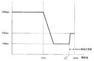
次に、蓋16の閉じる速度について図4を参照にして説明する。図4は、開口141の閉じ状態と蓋16の閉じる速度との関係を説明するための図である。図4では、横軸に、開口141の閉領域を百分率で示す。閉領域50%は、開口141が半分閉じられた状態を示す。閉領域100%は、開口141が全部閉じられた状態を示す。図4に示すポイントC1は、開口141の全部を閉じる直前の位置に相当する。ポイントC1から閉領域100%までの間の領域は、オペレータが指を差し込むことのできない隙間に相当している。その隙間は例えば、8[mm]である。その隙間は、指を差しこむことのできない隙間であるから、当然に、手や腕を差し込むことのできない隙間である。
Next, the closing speed of the
なお、制御部24が駆動部25を制御して、蓋16を閉じさせる閉領域は、50%に限らない。開口141の約半分まで閉じさせれば良い。開口141の約半分としては、例えば、閉領域40%から60%である。また、制御部24が駆動部25を制御して、蓋16を開口141の全部を閉じる直前の位置は、ポイントC1に限らない。例えば、蓋16と開口141の縁との間に、手や腕が挟まれない隙間を形成する位置であれば良い。
Note that the closed region in which the
図4に示すように、蓋16が開口141の半分を閉じるまで、入力パルス数は1000[pps]である。また、入力パルス数は、開口141の半分を閉じてから開口141の全部を閉じる直前のポイントC1までの間で、1000[pps]から250[pps]に徐々に低下する。さらに、入力パルス数は、直前のポイントC1から開口141の全部を閉じるまでの間で、250[pps]から500[pps]に徐々に向上する。
As shown in FIG. 4, the number of input pulses is 1000 [pps] until the
制御部24は、収納庫14の開口141を開いてからの継続時間(tx)が予め定められた時間(ts)を超えたとき、駆動部25を制御して、蓋16を開口141の全部まで閉じさせる。タイマー22は、開口141を開いてからの継続時間(tx)を計測する。継続時間(tx)が予め定められた時間の半分(ts/2)を超えたことの判定部23の情報を受けて、制御部24は、開放カウンタをインクリメント(+1)する。さらに、継続時間(tx)が予め定められた時間の半分(ts/2)を超えたことの判定部23の情報を受けて、制御部24は、開放カウンタをインクリメント(+1)する。
When the continuation time (tx) after opening the
制御部24は、開放カウンタの値が2以上でないとき、測定温度(Tx)が第1基準温度(Ts)を超えていなければ、開放カウンタをインクリメントする。制御部24は、測定温度(Tx)が第1基準温度(Ts)を超えていれば、駆動部25を制御して蓋16を開口141の約半分までを閉じさせた上で、開放カウンタをインクリメントする。制御部24は、開放カウンタの値が2以上であるとき、開口141の閉領域0%である全開状態であるか、又は、閉領域50%である半分閉じられた状態であるか否かに関係なく、駆動部25を制御して、蓋16を開口141の全部まで閉じさせる。また、制御部24は、蓋16の閉じ動作を行うとき、ブザー26を鳴動させる。
When the value of the open counter is not 2 or more and the measured temperature (Tx) does not exceed the first reference temperature (Ts), the
なお、蓋16の自動開閉を行うための自動開閉スイッチ27が設けられている。自動開閉スイッチがオンのとき、判定部23は、継続時間(tx)が予め定められた時間の半分(tx/2)を超えたか否かを繰り返し判定する。
An automatic opening /
また、カバー13が装置本体11の開口12を閉じたことを検出するカバースイッチ28が設けられている。開口12を閉じたことのカバースイッチ28の検出情報を受けたとき、制御部24は、駆動部25を制御して、蓋16を開口141の全部までを閉じさせる。装置本体11の開口12を閉じた場合、オペレータは手や腕を装置本体11の内部に入れようがないので、安全に開口141の全部まで閉じることができる。
A
(動作)
図5は、蓋の閉じ動作を示すフロー図である。次に、収納庫14の蓋16の閉じ動作について、図5のフロー図を参照にして説明する。
(Operation)
FIG. 5 is a flowchart showing the closing operation of the lid. Next, the closing operation of the
まず、蓋16の自動開閉スイッチがオンであるか否かを制御部24が判断する(ステップS101)。自動開閉スイッチ27がオンでない場合(ステップS101;N)、制御部24が開放カウンタを0にリセットする(ステップS102)。その後、自動開閉スイッチ27がオンでかるか否かを判断する(ステップS101)に戻る。自動開閉スイッチ27がオンである場合(ステップS101;Y)、判定部23は、蓋16が収納庫14の開口141を開いてからの継続時間(tx)が予め定められた時間の半分(ts/2)を超えたか否かを繰り返し判定する(ステップS103)。
First, the
継続時間(tx)が予め定められた時間の半分(ts)を超えたと判定部23が判定した場合(ステップS103;Y)、制御部24は、装置本体11の開口12が閉じ状態であるか否かを、カバースイッチ28の検出情報に基づいて判断する(ステップS104)。装置本体11の開口12が閉じ状態である場合(ステップS104;Y)、オペレータが装置本体11の内部にアクセスすることができず、安全であるため、ブザー26を鳴動させることなく、制御部24は、駆動部25を制御して、蓋16を開口141の全部まで閉させる(ステップS112)。
When the
装置本体11の開口12が閉じ状態でない場合(ステップS104;N)、判定部23は、継続時間(tx)が予め定められた時間(ts)を超えたか否かを判定する。具体的には、判定部23は、開放カウンタの値が2以上であるかを判定する(ステップS105)。
When the
開放カウンタの値が2以上であり、継続時間(tx)が予め定められた時間(ts)を超えたかと判定部23が判定した場合(ステップS105;Y)、制御部24は、ブザー26を鳴動させ(ステップS111)、駆動部25を制御して、蓋16を開口141の全部まで閉じる(ステップS112)。次に、制御部24は、開放カウンタを0にリセットする(ステップS113)。
When the
開放カウンタの値が2未満であり、継続時間(tx)が予め定められた時間(ts)を超えてないと判定部23が判定した場合(ステップS105;N)、判定部23は、収納庫14の内部の測定温度(Tx)を取得する(ステップS106)。
When the
次に、判定部23は、測定温度(Tx)が予め定められた第1設定温度(T1)を超えたか否かを判定する。また、判定部23は、測定温度(Tx)が第1設定温度(T1))より高い予め定められた第2設定温度(T2)を超えたか否かを判定する(ステップS107)。
Next, the
測定温度(Tx)が第1設定温度(T1)を超えないと判定部23が判定した場合、具体的には、測定温度(Tx)と基準温度(Ts)との温度差(Tx−Ts)が第1基準温度差(Ta1=1℃)に満たないと判定部23が判定した場合(ステップS107;1℃未満)、蓋16の閉じ動作を行うことなく、制御部24は、開放カウンタをインクリメント(+1)する(ステップS110)。
When the
測定温度(Tx)が第1設定温度(T1)を超えたと判定部23が判定した場合、具体的には、測定温度(Tx)と基準温度(Ts)との温度差(Tx−Ts)が第1基準温度差(1℃=<Ta1<3℃)であると判定部23が判定した場合(ステップS107;1℃以上3℃未満)、制御部24は、ブザー26を鳴動させる(ステップS108)。ブザー26を鳴動させることにより、蓋16の閉じ動作をオペレータに対して認識させることができる。
When the
次に、制御部24は、駆動部25を制御して、蓋16を開口141の約半分まで閉じさせる(ステップS109)。開口141を約半分まで閉じることによっても、蓋16の閉じ動作をオペレータに認識させることができ、蓋に手や腕を挟まれずに、安全に開口を閉じることができる。次に、制御部24は、開放カウンタをインクリメント(+1)する(ステップS110)。
Next, the
測定温度(Tx)が第2設定温度(Ta2)を超えたこと判定部23が判定した場合、具体的には、測定温度(Tx)と基準温度(Ts)との温度差(Tx−Ts)が第2基準温度差(Ta2=>3℃)であると判定部23が判定した場合(ステップS107;3℃以上)、制御部24は、ブザー26を鳴動させる(ステップS111)。ブザー26を鳴動させることにより、蓋16の閉じ動作をオペレータに対して認識させることができる。次に、制御部24は駆動部25を制御して、蓋16を開口141の全部まで閉じさせる(ステップS112)。次に、制御部24は、開放カウンタを0にリセットする(ステップS113)。
When the
蓋16を開口141の全部まで閉じさせるステップS112では、蓋16が開口141の約半分まで閉じてから開口141の全部まで閉じる直前までの間(図4において、閉領域50%からポイントC1までの間)、制御部24は、駆動部25を制御して、蓋16が開口141を閉じるに応じて、蓋16の閉じる速度を低下させる。蓋16の閉じる速度を、開口141を約半分まで閉じるときの速度の1/4に低下させるために、駆動部25のステッピングモータ(図示省略)への入力パルス数を1000[pps]から250[pps]に低下させる。
In step S112 in which the
蓋16の閉じる速度を低下させることにより、手や腕を開口141から待避させるための十分な時間をオペレータに与えることができ、安全に開口141を閉じることができる。また、速度が下がると同時にトルクも大幅に低下しているので、仮に、蓋16に手や腕を挟まれた場合であっても、その挟む力は小さいため、安全である。
By reducing the closing speed of the
図4に示すポイントC1から開口141の全部を閉じるまでの間、制御部24は、駆動部25を制御して、蓋16が開口141を閉じるに応じて、蓋16の閉じる速度を上げる。蓋16の閉じる速度を、開口141を約半分まで閉じるときの速度の1/4から1/2に上げるために、駆動部25のステッピングモータ(図示省略)への入力パルス数を250[pps]から500[pps]に上げる。また、速度の上昇によりトルクも大きくなるため、開口12を確実に閉じることができる。
From the point C <b> 1 shown in FIG. 4 until the
また、図4に示すポイントC1から開口141の全部を閉じるまでの間の隙間は、8[mm]であるため、その隙間にオペレータの手や腕が入らず、トルクを上げても安全である。
Further, since the gap between the point C1 and the
なお、前記実施形態では、蓋16がスライドすることにより、開口141を開閉する蓋16の開閉構造を示したが、これに限らない。収納庫の開口141を開閉する蓋の開閉構造であれば良い。例えば、図6に示す蓋16の開閉構造であっても良い。図6は、他の実施形態に係る自動分析装置の収納庫の内部を示す斜視図である。
In the above embodiment, the opening / closing structure of the
制御部24は、駆動部25を制御して、半円盤形の蓋16を略90度に起立させることにより、開口141を全開にし、半円盤形の蓋16を略45度に起立させることにより、開口141の約半分を閉じさせ、半円盤形の蓋16を水平に倒伏させることにより、開口141の全部を閉じさせる。開口141の全部を開いた蓋16を図6において一点鎖線で示す。開口141の全部まで閉じた蓋16を図6において実線で示す。
The
図6に示す蓋16の閉じ動作も、前記実施形態にかかる図2に示す蓋16の閉じ動作と同じである。例えば、制御部24は、駆動部25を制御して、蓋16の開口141の約半分を閉じてから開口141の全部を閉じる直前までの間、蓋16の閉じる速度を低下させる。
The closing operation of the
Tx 測定温度 T1 第1設定温度 T2 第2設定温度 Ts 基準温度
Ta1 第1基準温度差 Ta2 第2基準温度差 tx 継続時間
ts 予め定められた時間
10 自動分析装置 11 装置本体 12 装置本体の開口
13 カバー 14 収納庫 14a 円筒状下部 14b 円板状上部
141 収納庫の開口 142 容器 143 通過穴 15 反応庫
16 蓋 161 貫通穴 17 アーム
21 温度センサ 22 タイマー 23 判定部 24 制御部
25 駆動部 26 ブザー 27 自動開閉スイッチ 28 カバースイッチ
Tx measurement temperature T1 first set temperature T2 second set temperature Ts reference temperature Ta1 first reference temperature difference Ta2 second reference temperature difference tx duration ts
Claims (9)
前記収納庫に設けられた開口を開閉する蓋と、
前記蓋を開閉動作させる駆動手段と、
前記収納庫の内部の温度を測定する温度センサと、
前記温度センサにより測定された前記収納庫の内部の測定温度が、予め定められた設定温度を超えた場合、前記駆動手段に対して前記蓋が初期の段階で前記開口の一部を閉じるよう制御するとともに、その後の段階で前記開口の全部を閉じるよう制御する制御手段と、
を有することを特徴とする自動分析装置。 An apparatus main body provided with a storage for storing a container for containing at least one of a reagent, a sample, and a detergent;
A lid that opens and closes an opening provided in the storage;
Driving means for opening and closing the lid;
A temperature sensor for measuring the temperature inside the storage;
When the measured temperature inside the storage case measured by the temperature sensor exceeds a predetermined set temperature, the lid is controlled to close a part of the opening at an initial stage with respect to the driving means. And control means for controlling to close all of the openings at a later stage ;
The automatic analyzer characterized by having.
前記制御手段は、前記測定温度が前記予め定められた第1設定温度を超えた場合、前記駆動手段を制御して、前記蓋を前記開口の一部を閉じるよう制御し、前記測定温度が前記第2設定温度を超えた場合、前記駆動手段を制御して前記蓋が前記開口の全部を閉じるよう制御することを特徴とする請求項1記載の自動分析装置。 The predetermined set temperature is a first set temperature and a second set temperature higher than the first set temperature,
The control means controls the driving means to control the lid to close a part of the opening when the measured temperature exceeds the predetermined first set temperature, and the measured temperature is 2. The automatic analyzer according to claim 1, wherein when the second set temperature is exceeded, the driving means is controlled so that the lid closes all of the openings.
さらに、前記制御手段は、前記カバーが前記装置本体の開口を閉じたことの情報を受けたとき、前記蓋が前記収納庫の開口を開いていた場合に、前記駆動手段に対して、前記蓋が前記開口の全部をまで閉じるよう制御することを特徴とする請求項1に記載の自動分析装置。 By opening and closing the opening of the apparatus body, it has a cover that blocks the inside of the apparatus body from the outside,
Further, the control means receives the information that the cover has closed the opening of the apparatus main body, and when the cover has opened the opening of the storage case, the control means The automatic analyzer according to claim 1, wherein the automatic analyzer is controlled to close all the openings.
を有することを特徴とする自動分析装置の収納庫の蓋駆動方法。 When the measured temperature inside the container that contains at least the container for storing any liquid of the reagent, sample, and detergent exceeds a predetermined set temperature, the drive means is controlled to be provided in the container. A lid for opening and closing the opening is controlled to close a part of the opening at an initial stage, and is controlled to close all of the opening at a later stage ;
A lid driving method for a storage of an automatic analyzer characterized by comprising:
Priority Applications (1)
| Application Number | Priority Date | Filing Date | Title |
|---|---|---|---|
| JP2008261980A JP5175679B2 (en) | 2008-10-08 | 2008-10-08 | Automatic analyzer and lid driving method for the storage |
Applications Claiming Priority (1)
| Application Number | Priority Date | Filing Date | Title |
|---|---|---|---|
| JP2008261980A JP5175679B2 (en) | 2008-10-08 | 2008-10-08 | Automatic analyzer and lid driving method for the storage |
Publications (3)
| Publication Number | Publication Date |
|---|---|
| JP2010091427A JP2010091427A (en) | 2010-04-22 |
| JP2010091427A5 JP2010091427A5 (en) | 2011-11-24 |
| JP5175679B2 true JP5175679B2 (en) | 2013-04-03 |
Family
ID=42254285
Family Applications (1)
| Application Number | Title | Priority Date | Filing Date |
|---|---|---|---|
| JP2008261980A Expired - Fee Related JP5175679B2 (en) | 2008-10-08 | 2008-10-08 | Automatic analyzer and lid driving method for the storage |
Country Status (1)
| Country | Link |
|---|---|
| JP (1) | JP5175679B2 (en) |
Families Citing this family (2)
| Publication number | Priority date | Publication date | Assignee | Title |
|---|---|---|---|---|
| JP5903054B2 (en) * | 2013-02-01 | 2016-04-13 | 株式会社日立ハイテクノロジーズ | Automatic analyzer |
| CN107850609B (en) * | 2014-07-30 | 2020-04-21 | 株式会社日立高新技术 | Automatic analyzer |
Family Cites Families (10)
| Publication number | Priority date | Publication date | Assignee | Title |
|---|---|---|---|---|
| JPH0720554B2 (en) * | 1987-05-28 | 1995-03-08 | 日本テクトロン株式会社 | Opening / closing device for reagent bottle table |
| JPH0750712Y2 (en) * | 1988-12-29 | 1995-11-15 | 株式会社島津製作所 | Refrigerating reagent storage of automatic biochemical analyzer |
| JPH02306082A (en) * | 1989-05-19 | 1990-12-19 | Nec Corp | Cold storage |
| JP4248470B2 (en) * | 2004-09-17 | 2009-04-02 | 株式会社日立ハイテクノロジーズ | Automatic analyzer |
| JP4961120B2 (en) * | 2005-08-04 | 2012-06-27 | ベックマン コールター, インコーポレイテッド | Reagent cooler |
| JP3808895B2 (en) * | 2005-12-26 | 2006-08-16 | 東芝メディカルシステムズ株式会社 | Automatic analyzer |
| JP2008020360A (en) * | 2006-07-13 | 2008-01-31 | Olympus Corp | Autoanalyzer and reagent container |
| JP5032088B2 (en) * | 2006-10-10 | 2012-09-26 | シスメックス株式会社 | Analyzer and reagent container |
| JP5122797B2 (en) * | 2006-12-06 | 2013-01-16 | 株式会社東芝 | Automatic analyzer |
| JP2008216173A (en) * | 2007-03-07 | 2008-09-18 | Toshiba Corp | Automatic analyzer |
-
2008
- 2008-10-08 JP JP2008261980A patent/JP5175679B2/en not_active Expired - Fee Related
Also Published As
| Publication number | Publication date |
|---|---|
| JP2010091427A (en) | 2010-04-22 |
Similar Documents
| Publication | Publication Date | Title |
|---|---|---|
| JP5674440B2 (en) | Automatic analyzer | |
| US10908175B2 (en) | Sample analyzer and liquid aspirating method | |
| EP2703819B1 (en) | Sample processing apparatus and sample processing method | |
| JP5175679B2 (en) | Automatic analyzer and lid driving method for the storage | |
| JP2008070355A5 (en) | ||
| JP2015537224A (en) | Dispenser for electrochemical sensors | |
| JPWO2020235134A5 (en) | ||
| EP2952903B1 (en) | Automated analyzer | |
| JP5860725B2 (en) | Automatic analyzer | |
| JP2006300847A (en) | Reagent cold-retaining chamber and automatic analysis apparatus with same | |
| JP6091964B2 (en) | Automatic analyzer | |
| EP3855188B1 (en) | Automatic analysis device | |
| JP2012098139A (en) | Reagent container lid open/close mechanism and automatic analysis device having the same | |
| JP2010091427A5 (en) | ||
| JP5899302B2 (en) | Automatic analyzer | |
| EP3623817B1 (en) | Analyzer | |
| JP6249653B2 (en) | Automatic analyzer | |
| JP2013024797A (en) | Analyzer and analysis method | |
| JP6579243B2 (en) | Dispensing device and automatic analyzer equipped with the same | |
| JP7054620B2 (en) | Automatic analyzer and automatic analysis method | |
| JP6878140B2 (en) | Clinical laboratory equipment | |
| JP3200940U (en) | Dispensing device and automatic analyzer equipped with the same | |
| JP2010054476A5 (en) | ||
| EP4180366A1 (en) | Test strip container and test strip discharging mechanism | |
| EP4180367A1 (en) | Test strip holder and test strip discharging mechanism |
Legal Events
| Date | Code | Title | Description |
|---|---|---|---|
| A521 | Written amendment |
Free format text: JAPANESE INTERMEDIATE CODE: A523 Effective date: 20111011 |
|
| A621 | Written request for application examination |
Free format text: JAPANESE INTERMEDIATE CODE: A621 Effective date: 20111011 |
|
| A977 | Report on retrieval |
Free format text: JAPANESE INTERMEDIATE CODE: A971007 Effective date: 20120919 |
|
| A131 | Notification of reasons for refusal |
Free format text: JAPANESE INTERMEDIATE CODE: A131 Effective date: 20120925 |
|
| A521 | Written amendment |
Free format text: JAPANESE INTERMEDIATE CODE: A523 Effective date: 20121121 |
|
| TRDD | Decision of grant or rejection written | ||
| A01 | Written decision to grant a patent or to grant a registration (utility model) |
Free format text: JAPANESE INTERMEDIATE CODE: A01 Effective date: 20121211 |
|
| A61 | First payment of annual fees (during grant procedure) |
Free format text: JAPANESE INTERMEDIATE CODE: A61 Effective date: 20130107 |
|
| R150 | Certificate of patent or registration of utility model |
Ref document number: 5175679 Country of ref document: JP Free format text: JAPANESE INTERMEDIATE CODE: R150 |
|
| S111 | Request for change of ownership or part of ownership |
Free format text: JAPANESE INTERMEDIATE CODE: R313117 |
|
| R350 | Written notification of registration of transfer |
Free format text: JAPANESE INTERMEDIATE CODE: R350 |
|
| S533 | Written request for registration of change of name |
Free format text: JAPANESE INTERMEDIATE CODE: R313533 |
|
| R350 | Written notification of registration of transfer |
Free format text: JAPANESE INTERMEDIATE CODE: R350 |
|
| LAPS | Cancellation because of no payment of annual fees |